mount polley mining corporation · mount polley mining corporation. m. ount . p. olley . m. ine. t....
TRANSCRIPT
MOUNT POLLEY MINING CORPORATION
MOUNT POLLEY MINE
TAILINGS STORAGE FACILITY
OPERATION, MAINTENANCE AND SURVEILLANCE MANUAL
AMEC010667_0001
MOUNT POLLEY MINING CORPORATION
MOUNT POLLEY MINE
TAILINGS STORAGE FACILITY
OPERATION, MAINTENANCE AND SURVEILLANCE MANUAL
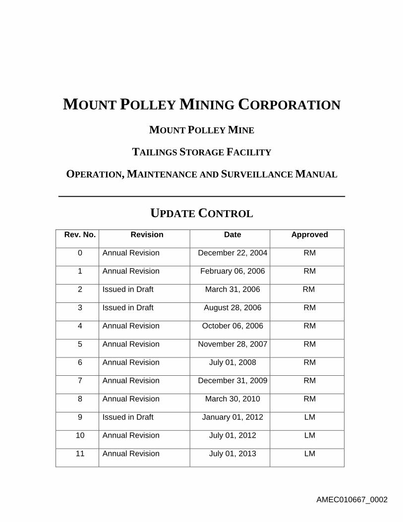
UPDATE CONTROL
Rev. No. Revision Date Approved
0 Annual Revision December 22, 2004 RM
1 Annual Revision February 06, 2006 RM
2 Issued in Draft March 31, 2006 RM
3 Issued in Draft August 28, 2006 RM
4 Annual Revision October 06, 2006 RM
5 Annual Revision November 28, 2007 RM
6 Annual Revision July 01, 2008 RM
7 Annual Revision December 31, 2009 RM
8 Annual Revision March 30, 2010 RM
9 Issued in Draft January 01, 2012 LM
10 Annual Revision July 01, 2012 LM
11 Annual Revision July 01, 2013 LM
AMEC010667_0002

i of viii
MOUNT POLLEY MINING CORPORATION
MOUNT POLLEY MINE
TAILINGS STORAGE FACILITY
OPERATION, MAINTENANCE AND SURVEILLANCE MANUAL
KP ULTIMATE ELEVATION DESIGN REF. NO. VA101-001/08-1
AMEC CONSTRUCTION MONITORING MANUAL FILE NO. VM00560C
TABLE OF CONTENTS
PAGE
1.0 OBJECTIVE ....................................................................................................................................... 1
2.0 ROLES AND RESPONSIBILITIES ............................................................................................. 2
2.1 MANAGEMENT STRUCTURE ..................................................................................................................... 5
2.2 DESIGN GROUP (AMEC) ........................................................................................................................ 5
2.3 REGULATORY GROUP (MINISTRY OF ENERGY AND MINES) ............................................................................ 5
2.4 CONSTRUCTION GROUP .......................................................................................................................... 6
2.4.1 MPMC Field Inspector and Mine Technicians ......................................................................... 6
2.4.2 AMEC Support Engineer .......................................................................................................... 6
2.4.3 AMEC Project Manager .......................................................................................................... 6
2.4.4 AMEC Senior Geotechnical Engineer....................................................................................... 7
2.4.5 MPMC Project Manager ......................................................................................................... 7
2.4.6 MPMC Mine Operations Manager .......................................................................................... 7
2.5 OPERATION, MAINTENANCE AND SURVEILLANCE ......................................................................................... 8
2.5.1 Mine Manager ........................................................................................................................ 8
2.5.2 Tailings Project Manager ........................................................................................................ 8
2.5.3 Mine Operations Manager ..................................................................................................... 8
2.5.4 Environmental Superintendent ............................................................................................... 8
2.5.5 Mill Maintenance Superintendent .......................................................................................... 9
2.5.6 Mill Operations Superintendent .............................................................................................. 9
2.5.7 Senior Safety Co-ordinator ...................................................................................................... 9
2.6 COMPETENCY AND TRAINING................................................................................................................... 9
2.7 MANAGING CHANGE ........................................................................................................................... 10
AMEC010667_0003
ii of viii
3.0 FACILITY DESCRIPTION ........................................................................................................ 11
3.1 FACILITY OVERVIEW ............................................................................................................................. 11
3.1.1 Ownership ............................................................................................................................. 11
3.1.2 Location ................................................................................................................................ 11
3.1.3 Site Layout Plan .................................................................................................................... 12 3.1.3.1 Water Management ................................................................................................................... 14
3.1.4 Mine Operation History ........................................................................................................ 16
3.1.5 Mineralization ....................................................................................................................... 16
3.1.6 Mining ................................................................................................................................... 16
3.1.7 Milling Process ...................................................................................................................... 17
3.1.8 Tailings Management ........................................................................................................... 17
3.2 SITE CONDITIONS ................................................................................................................................ 18
3.2.1 Climate .................................................................................................................................. 18
3.2.2 Land Surface Drainage .......................................................................................................... 18
3.2.3 Hydrology and Water Quality ............................................................................................... 22
3.2.4 Geology ................................................................................................................................. 24
3.2.5 Surrounding Land Use and Tenure ........................................................................................ 24
3.2.6 Vegetation and Wildlife ........................................................................................................ 25
4.0 KEY COMPONENTS OF THE FACILITY ............................................................................................. 26
4.1 WATER MANAGEMENT ........................................................................................................................ 26
4.1.1 Mine-Influenced Water Ditch and Sump Systems ................................................................. 26 4.1.1.1 Pit Dewatering ........................................................................................................................... 26 4.1.1.2 Northwest PAG Sump and Ditch System .................................................................................... 27 4.1.1.3 Mine Drainage Creek Sump........................................................................................................ 27 4.1.1.4 Wight Pit Dewatering ................................................................................................................. 27 4.1.1.5 SEZ Sump .................................................................................................................................... 27 4.1.1.6 Joe’s Creek Coffer Dam and Pipe ............................................................................................... 27 4.1.1.7 Long Ditch .................................................................................................................................. 27 4.1.1.8 Long Ditch Sump ........................................................................................................................ 27 4.1.1.9 Orica Ditch ................................................................................................................................. 28 4.1.1.10 SERDS Ditch ................................................................................................................................ 28 4.1.1.11 SERDS Sump ............................................................................................................................... 28 4.1.1.12 Perimeter Pond Ditch ................................................................................................................. 28 4.1.1.13 Mill Site Ditch ............................................................................................................................. 28 4.1.1.14 Mill Site Sump ............................................................................................................................ 28 4.1.1.15 Geology Wastewater.................................................................................................................. 29 4.1.1.16 TSF Embankment Seepage Ponds .............................................................................................. 29 4.1.1.17 Anaerobic Biological Reactor ..................................................................................................... 29 4.1.1.18 Reclaimed Water ........................................................................................................................ 29
4.1.2 Clean Water Ditch and Sump Systems .................................................................................. 29 4.1.2.1 New Access Road ....................................................................................................................... 29 4.1.2.2 Joe’s Creek (Clean Water) aka North Dump Creek ..................................................................... 30 4.1.2.3 TSF Clean Water Ditch (Corner 5 to Corner 4) ........................................................................... 30 4.1.2.4 Bootjack Creek ........................................................................................................................... 30 4.1.2.5 Corner 5 Clean Water Ditch ....................................................................................................... 30 4.1.2.6 Mill Site (Clean Water) ............................................................................................................... 30 4.1.2.7 Wight Pit (Clean Water) ............................................................................................................. 30
4.1.3 Dust Control Systems ............................................................................................................ 31 4.1.3.1 Springer Pit Water Filling Station ............................................................................................... 31
AMEC010667_0004

iii of viii
4.1.3.2 SERDS Water Filling Station ........................................................................................................ 31 4.1.3.3 Tailings Water Filling Station ...................................................................................................... 31 4.1.3.4 TSF Sprinklers ............................................................................................................................. 31 4.1.3.5 NEZ Dump Sprinklers.................................................................................................................. 31 4.1.3.6 High Ox Dump Sprinklers ........................................................................................................... 31
4.2 TAILINGS MANAGEMENT ...................................................................................................................... 32
4.2.1 Tailings Line .......................................................................................................................... 32
4.2.2 TSF Facility ............................................................................................................................ 34
4.3 INSTRUMENTATION.............................................................................................................................. 34
4.3.1 Geotechnical Instrumentation .............................................................................................. 34 4.3.1.1 Inclinometers ............................................................................................................................. 34 4.3.1.2 Vibrating Wire Piezometers ....................................................................................................... 34
4.3.2 Groundwater Wells ............................................................................................................... 35
5.0 ENGINEERING AND DESIGN OF COMPONENTS ............................................................... 37
5.1 WATER MANAGEMENT ........................................................................................................................ 37
5.1.1 Mine-Influenced Water Systems ........................................................................................... 37 5.1.1.1 Pit Dewatering ........................................................................................................................... 37 5.1.1.2 Northwest PAG Sump and Ditch System .................................................................................... 37 5.1.1.3 Mine Drainage Creek Sump........................................................................................................ 38 5.1.1.4 Wight Pit Dewatering ................................................................................................................. 38 5.1.1.5 SEZ Sump .................................................................................................................................... 40 5.1.1.6 Joe’s Creek Coffer Dam and Pipe ............................................................................................... 41 5.1.1.7 Long Ditch .................................................................................................................................. 42 5.1.1.8 Long Ditch Sump ........................................................................................................................ 43 5.1.1.9 Orica Ditch ................................................................................................................................. 44 5.1.1.10 SERDS Ditch ................................................................................................................................ 45 5.1.1.11 SERDS Sump ............................................................................................................................... 45 5.1.1.12 Perimeter Pond Ditch ................................................................................................................. 45 5.1.1.13 Mill Site Ditch ............................................................................................................................. 47 5.1.1.14 Mill Site Sump ............................................................................................................................ 47 5.1.1.15 Geology Wastewater.................................................................................................................. 47 5.1.1.16 TSF Embankment Seepage Ponds .............................................................................................. 48 5.1.1.17 Anaerobic Biological Reactor ..................................................................................................... 48 5.1.1.18 Reclaimed Water ........................................................................................................................ 50
5.1.2 Clean Water Systems ............................................................................................................ 52 5.1.2.1 New Access Road ....................................................................................................................... 53 5.1.2.2 Joe’s Creek (Clean Water) aka North Dump Creek ..................................................................... 53 5.1.2.3 TSF Clean Water Ditch (Corner 5 to Corner 4) ........................................................................... 53 5.1.2.4 Bootjack Creek ........................................................................................................................... 54 5.1.2.5 Corner 5 Clean Water Ditch ....................................................................................................... 55 5.1.2.6 Mill Site (Clean Water) ............................................................................................................... 55 5.1.2.7 Wight Pit (Clean Water) ............................................................................................................. 56
5.1.3 Dust Control Systems ............................................................................................................ 57 5.1.3.1 Springer Pit Water Filling Station ............................................................................................... 57 5.1.3.2 SERDS Water Filling Station ........................................................................................................ 57 5.1.3.3 Tailings Water Filling Station ...................................................................................................... 57 5.1.3.4 TSF Sprinklers ............................................................................................................................. 57 5.1.3.5 NEZ Dump Sprinklers.................................................................................................................. 57 5.1.3.6 High Ox Dump Sprinklers ........................................................................................................... 57
5.2 TAILINGS MANAGEMENT ...................................................................................................................... 57
AMEC010667_0005
iv of viii
5.2.1 Tailings Line .......................................................................................................................... 58
5.2.2 TSF Facility ............................................................................................................................ 58 5.2.2.1 Design Consultant ...................................................................................................................... 59 5.2.2.2 As-Built Report/Annual Review .................................................................................................. 60
5.3 INSTRUMENTATION.............................................................................................................................. 60
5.3.1 Geotechnical Instrumentation .............................................................................................. 60
5.3.2 Groundwater Wells ............................................................................................................... 60
6.0 OPERATION .............................................................................................................................. 61
6.1 WATER MANAGEMENT ........................................................................................................................ 61
6.1.1 Sump and Ditch Systems ....................................................................................................... 61
6.1.2 TSF Embankment Seepage Collection Ponds ........................................................................ 62
6.2 RECLAIM BARGE AND PIPELINE .............................................................................................................. 62
6.3 TAILINGS BASIN .................................................................................................................................. 62
6.4 TAILINGS TRANSPORT AND DEPOSITION ................................................................................................... 63
6.4.1 Tailings Properties ................................................................................................................ 64
6.4.2 Deposition Management ...................................................................................................... 64
6.4.3 Beach Management ............................................................................................................. 65
6.4.4 Sand Cells .............................................................................................................................. 65
6.4.5 Tailings Pipe .......................................................................................................................... 66
6.5 INSTRUMENTATION.............................................................................................................................. 66
6.5.1 Geotechnical Instrumentation .............................................................................................. 66 6.5.1.1 Inclinometers ............................................................................................................................. 67 6.5.1.2 Vibrating Wire Piezometers ....................................................................................................... 67
6.5.2 Groundwater Wells ............................................................................................................... 68
7.0 MAINTENANCE AND SURVEILLANCE ................................................................................ 69
7.1 GENERAL ........................................................................................................................................... 69
7.2 WATER MANAGEMENT SYSTEMS ........................................................................................................... 69
7.3 TAILINGS POND .................................................................................................................................. 70
7.4 TAILINGS EMBANKMENT ....................................................................................................................... 70
7.5 TAILINGS DISCHARGE PIPELINE ............................................................................................................... 71
7.6 RECLAIM PIPELINE ............................................................................................................................... 71
7.7 INSTRUMENTATION.............................................................................................................................. 72
7.7.1 Geotechnical Instrumentation .............................................................................................. 72
7.7.2 Groundwater Wells ............................................................................................................... 72
8.0 DOCUMENTATION .................................................................................................................. 73
8.1 DESIGN CONSULTANT AS-BUILT REPORT ................................................................................................. 73
8.2 DAM SAFETY REVIEW ........................................................................................................................... 74
9.0 EMERGENCY PROCEDURES ................................................................................................. 75
9.1 GENERAL ........................................................................................................................................... 75
9.2 WARNING SIGNS ................................................................................................................................. 75
9.2.1 Level 1 ................................................................................................................................... 75
9.2.2 Level 2 ................................................................................................................................... 76
9.2.3 Level 3 ................................................................................................................................... 76
9.3 SITUATIONS........................................................................................................................................ 76
AMEC010667_0006

v of viii
9.3.1 Level 1 Situation .................................................................................................................... 76
9.3.2 Level 2 Situation .................................................................................................................... 76
9.3.3 Level 3 Situation .................................................................................................................... 76
9.4 INCIDENT NOTIFICATION PROCEDURES .................................................................................................... 77
9.4.1 Level 1 and Level 2 ................................................................................................................ 77
9.4.2 Level 3 ................................................................................................................................... 77
10.0 REFERENCE DOCUMENTS ................................................................................................ 78
11.0 CERTIFICATION AND DISTRIBUTION ............................................................................ 79
11.1 CONTROL OF THIS MANUAL .............................................................................................................. 79
11.2 DISTRIBUTION OF THE MANUAL ........................................................................................................ 79
11.3 CERTIFICATION OF THE MANUAL ....................................................................................................... 80
AMEC010667_0007
vi of viii
LIST OF FIGURES AND TABLES
FIGURE 3.1.2.1 - LOCATION MAP ........................................................................................................... 12
FIGURE 3.1.3.1 – 2012 SITE AERIAL......................................................................................................... 13
FIGURE 3.1.3.1.1 – WATER MANAGEMENT SCHEMATIC ......................................................................... 15
FIGURE 3.2.2.1 – AREA MAP ................................................................................................................... 19
FIGURE 3.2.2.2 – WATERSHED MAP ....................................................................................................... 21
FIGURE 3.2.3.1 – SAMPLING LOCATIONS MAP ....................................................................................... 23
FIGURE 4.2.1.1 - TAILINGS LINE MILL TO TSF .......................................................................................... 33
TABLE 4.3.2.1 – GROUNDWATER WELL COORDINATES .......................................................................... 36
FIGURE 5.1.1.2.1 - NW PAG DITCH AND SUMP SYSTEM.......................................................................... 38
FIGURE 5.1.1.4.1 – WIGHT PIT DEWATERING ......................................................................................... 40
FIGURE 5.1.1.6.1 – JOE’S CREEK COFFER DAM AND PIPE ........................................................................ 41
FIGURE 5.1.1.7.1 – LONG DITCH ............................................................................................................. 42
FIGURE 5.1.1.8.1 – LONG DITCH SUMP ................................................................................................... 43
FIGURE 5.1.1.9.1 – SERDS DITCH AND SUMP SYSTEM ............................................................................ 44
FIGURE 5.1.1.12.1 – PERIMETER POND DITCH ........................................................................................ 46
FIGURE 5.1.1.13.1 – MILL SITE SUMP AND DITCH SYSTEM ..................................................................... 47
FIGURE 5.1.1.17.1 – ABR PIPE SCHEMATIC ............................................................................................. 49
FIGURE 5.1.1.17.2 – ABR ORGANICS SCHEMATIC ................................................................................... 49
FIGURE 5.1.1.17.3 – ABR ORGANICS PLACEMENT ................................................................................... 50
FIGURE 5.1.1.17.4 – ABR FLOW .............................................................................................................. 50
FIGURE 5.1.1.18.1 – RECLAIM WATER SYSTEM ....................................................................................... 52
FIGURE 5.1.2.2.1 – JOE’S CREEK (CLEAN WATER) AKA NORTH DUMP CREEK .......................................... 53
FIGURE 5.1.2.3.1 – TSF CLEAN WATER DITCH ......................................................................................... 54
FIGURE 5.1.2.4.1 – BOOTJACK CREEK ..................................................................................................... 55
FIGURE 5.1.2.5.1 – CORNER 5 CLEAN WATER DITCH ............................................................................... 55
FIGURE 5.1.2.6.1 – MILL SITE (CLEAN WATER) ........................................................................................ 56
FIGURE 5.1.2.7.1 – WIGHT PIT CLEAN WATER ........................................................................................ 56
TABLE 6.4.1 – TAILINGS PROPERTIES ...................................................................................................... 64
AMEC010667_0008
vii of viii
APPENDICES
APPENDIX A REFERENCE DOCUMENTS
APPENDIX B WATER SAMPLING SITE COORDINATES
APPENDIX C PIEZOMETER AND INCLINOMETER LOCATIONS
APPENDIX D TAILINGS BASIN FILLING CURVE
APPENDIX E MPMC INTERNAL DOCUMENTS
AMEC010667_0009

viii of viii
LIST OF ABBREVIATIONS
ABR Anaerobic Biological Reactor
AMEC AMEC Environment & Infrastructure, a Division of AMEC Americas Limited
COI Communities of Interest
COO Chief Operating Officer
DSR Dam Safety Review
GPM Gallons Per Minute
Imperial Imperial Metals Corporation
KP Knight Piésold
MEM British Columbia Ministry of Energy and Mines
MESCP Main Embankment Seepage Collection Pond
Mines Act British Columbia Mines Act, Health & Safety Regulation Codes
MMER Metal Mines Effluent Regulation
MOE British Columbia Ministry of Environment
MPMC Mount Polley Mining Corporation
OMS Operations, Maintenance and Surveillance
PESCP Perimeter Embankment Seepage Collection Pond
PMP Probable Maximum Precipitation
SAG Semi-autonomous Grinding
SERDS Southeast Rock Dump Site
SESCP South Embankment Seepage Collection Pond
tpd tonnes per day
TSF Tailings Storage Facility
AMEC010667_0010
1 of 80
MOUNT POLLEY MINING CORPORATION
MOUNT POLLEY MINE
TAILINGS STORAGE FACILITY
OPERATION, MAINTENANCE AND SURVEILLANCE MANUAL
1.0 OBJECTIVE
This Operations, Maintenance and Surveillance (OMS) Manual applies to the Tailings Storage
Facility (TSF) and related water management structures at the Mount Polley mine. The OMS
Manual is a document mandated by the regulatory bodies governing the operation of Mount
Polley Mine.
Under the British Columbia Mines Act, Health & Safety Regulation Codes (Mines Act), Section
10.5.2, it is stated that, “An Operation, Maintenance and Surveillance (OMS) manual shall be
prepared and provided to an inspector and all employees involved in the operation of a major
dam or major impoundment prior to commissioning. This manual shall be revised regularly
during operations, decommissioning and closure of the structure”. The Mount Polley Mine TSF
falls under the “operating” category as outlined in the Mines Act.
Additionally, based on a Previous Permit M-200 amendment, entitled, “Amendment to Permit
M-200 Permit Approving Stage 8 Construction” executed for Al Hoffman, P.Eng, Chief
Inspector of Mines on June 29, 2012, the following regulatory conditions exist in regards to
construction of the TSF:
The Operation, Maintenance and Surveillance manual shall be updated in 2012 as
recommended in the 2011 As-Built report.
This OMS Manual describes the roles and responsibilities of Mount Polley site personnel for the
management of the TSF and associated facilities; describes in detail the facility; described
engineering and design of the components; establishes the procedures and processes for
operation, surveillance and maintenance of the facility; explains documentation associated with
the OMS; and, outlines emergency procedures.
AMEC010667_0011
2 of 80
2.0 ROLES AND RESPONSIBILITIES
Personnel involved in the safe operation, maintenance, surveillance and supervision of the TSF
and related water management infrastructure are not limited to those employed by Mount Polley.
In addition to the individuals interacting with the facilities on a first-hand basis, there is an
extensive group of design professionals and regulatory representatives involved in the successful
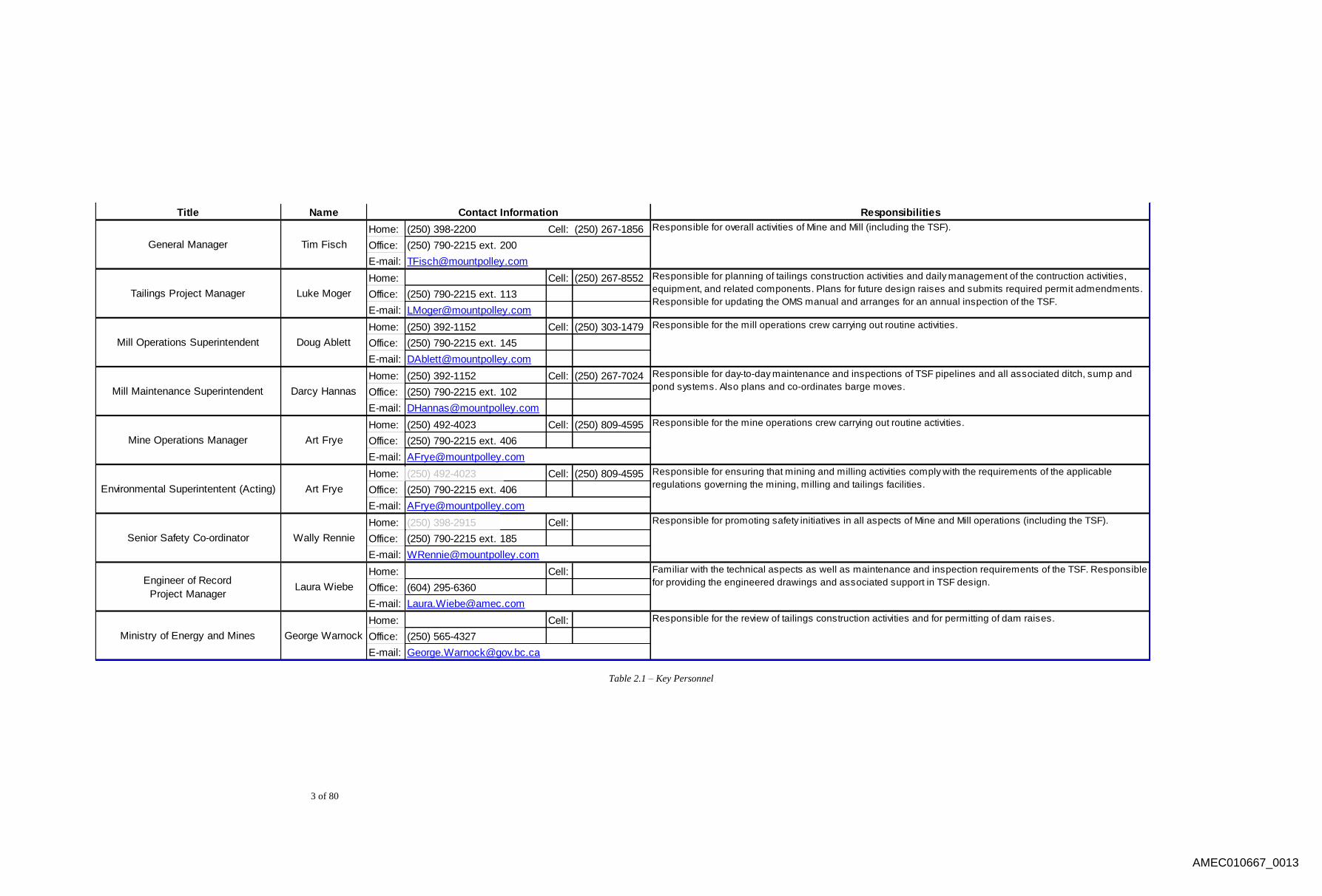
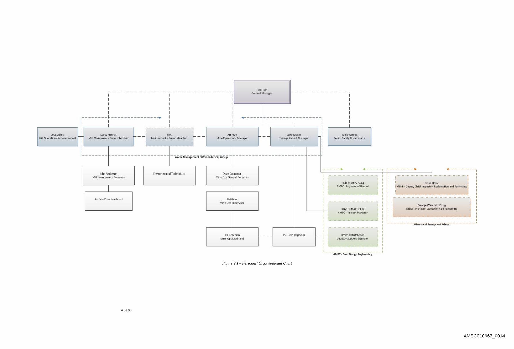
implementation of the OMS. Key personnel are identified in Table 2.1 – Key Personnel. An
organizational chart showing reporting links within the organization and communication links to
external organizations is included as Figure 2.1 – Personnel Organizational Chart.
AMEC010667_0012
3 of 80
Title Name Responsibilities
Home: (250) 398-2200 Cell: (250) 267-1856
Office: (250) 790-2215 ext. 200
E-mail:
Home: Cell: (250) 267-8552
Office: (250) 790-2215 ext. 113
E-mail: [email protected]
Home: (250) 392-1152 Cell: (250) 303-1479
Office: (250) 790-2215 ext. 145
E-mail: [email protected]
Home: (250) 392-1152 Cell: (250) 267-7024
Office: (250) 790-2215 ext. 102
E-mail: [email protected]
Home: (250) 492-4023 Cell: (250) 809-4595
Office: (250) 790-2215 ext. 406
E-mail:
Home: (250) 492-4023 Cell: (250) 809-4595
Office: (250) 790-2215 ext. 406
E-mail:
Home: (250) 398-2915 Cell:
Office: (250) 790-2215 ext. 185
E-mail:
Home: Cell:
Office: (604) 295-6360
E-mail:
Home: Cell:
Office: (250) 565-4327
E-mail:
General Manager
Responsible for overall activities of Mine and Mill (including the TSF).
Tim Fisch
Ministry of Energy and Mines
Contact Information
Engineer of Record
Project Manager
Environmental Superintentent (Acting)
Mine Operations Manager
Mill Maintenance Superintendent
Tailings Project Manager
George Warnock
Laura Wiebe
Art Frye
Art Frye
Darcy Hannas
Mill Operations Superintendent
Senior Safety Co-ordinator
Familiar with the technical aspects as well as maintenance and inspection requirements of the TSF. Responsible
for providing the engineered drawings and associated support in TSF design.
Responsible for the review of tailings construction activities and for permitting of dam raises.
Luke Moger
Responsible for the mine operations crew carrying out routine activities.
Responsible for planning of tailings construction activities and daily management of the contruction activities,
equipment, and related components. Plans for future design raises and submits required permit admendments.
Responsible for updating the OMS manual and arranges for an annual inspection of the TSF.
Responsible for day-to-day maintenance and inspections of TSF pipelines and all associated ditch, sump and
pond systems. Also plans and co-ordinates barge moves.
Responsible for ensuring that mining and milling activities comply with the requirements of the applicable
regulations governing the mining, milling and tailings facilities.
Doug Ablett
Responsible for the mill operations crew carrying out routine activities.
Wally Rennie
Responsible for promoting safety initiatives in all aspects of Mine and Mill operations (including the TSF).
Table 2.1 – Key Personnel
AMEC010667_0013
4 of 80
Figure 2.1 – Personnel Organizational Chart
AMEC010667_0014

5 of 80
Management Structure 2.1
The management structure consists of both internal (to Mount Polley) and external
individuals. Internally, there is a core leadership group consisting of the senior
representatives from all departments directly involved in the application of the OMS.
Included in this group (the Water Management OMS Leadership Group) are the Mill
Maintenance Superintendent, the Environmental Superintendent, the Mine Operations
Manager and the Tailings Project Manager. Though all direct reports to the Mine
Manager by position, for the purposes of the OMS, all efforts are collaborated through
one individual; the Tailings Project Manager. The Mill Operations Superintendent and
the Senior Safety Co-ordinator also compliment this team, but do not form the core
decision-making body for site-wide water management.
Direct reports (and associated structures) to the respective individuals in the Water
Management OMS Leadership Group still follow normal site-wide relationships in
application of the OMS. External individuals are co-ordinated through the Tailings
Project Manager through their respective representatives. Details of these positions are
graphically illustrated in Figure 2.1 – Organizational Chart with details of specific
positions and responsibilities being as further defined in this OMS.
Design Group (AMEC) 2.2
As per the Mines Act, “Major impoundments, water management facilities and dams
shall be designed in accordance with the criteria provided in the Canadian Dam
Association, Dam Safety Guidelines”. Additionally, “Tailings impoundments, water
management facilities, dams and waste dumps shall be designed by a professional
engineer” (Section 10.1.5 and Section 10.1.8 respectively).
In the case of the Mount Polley TSF, AMEC Environment & Infrastructure, a Division of
AMEC Americas Limited (AMEC) is the Design Engineer currently retained to fulfill
these requirements. The current working AMEC team consists of, in order of seniority:
Steve, P.Eng. (AMEC Principal Engineer); Laura Wiebe, P.Eng. (AMEC Project
Manager and Engineer of Record); and Dmitri Ostritchenko (AMEC Support Engineer).
Any deviation from permitted design documents requires the approval of the Design
Engineer as well as the British Columbia Ministry of Energy and Mines (MEM).
Regulatory Group (Ministry of Energy and Mines) 2.3
As-built and annual reports pertaining to the TSF are, each year, submitted to and
reviewed by representatives of the MEM. Based on the information in these reports
(reports being provided by the Design Engineers retained by Mount Polley mine), in
AMEC010667_0015
6 of 80
conjunction with annual construction manuals provided by the Design Engineer, MEM
permits each “phase” of TSF construction (historically on an annual basis).
Currently, the individual responsible for the review of all relevant technical information
pertaining to the TSF is the MEM Manager of Geotechnical Engineering: George
Warnock, P.Eng. The individual responsible for the amendment of the M-200 Mining
Permit in accordance with the proposed annual dam raise is the MEM Chief Inspector of
Mines, Al Hoffman, P.Eng.
Construction Group 2.4
During construction periods, roles and responsibilities of individuals involved will follow
that of the design consultant’s Annual Construction Manual.
2.4.1 MPMC Field Inspector and Mine Technicians
Mount Polley Mining Corporation (MPMC) is to provide a full-time field inspector to
monitor daily embankment expansion construction. The MPMC Field Inspector is to
have support and co-operation from the senior MPMC personnel and construction
team.
The specific responsibilities of MPMC’s Field Inspector are as outlined in the Annual
Construction Manual.
2.4.2 AMEC Support Engineer
The AMEC Support Engineer will provide full-time construction monitoring at the
commencement of construction. After the MPMC Field Inspector has achieved
sufficient confidence and commensurate approval, the AMEC Support Engineer will
provide primarily remote assistance by reviewing daily reports and instrumentation
data as required. The AMEC Support Engineer will also conduct monthly site visits
(actual frequency to be determined by site performance) to verify construction
methods and specifications are being followed.
The specific responsibilities of MPMC’s Field Inspector are as outlined in the Annual
Construction Manual.
2.4.3 AMEC Project Manager
AMEC’s Project Manager will have overall responsibility for AMEC’s role with
upcoming and future dam raising projects. AMEC’s Project Engineer will also act as
the Engineer of Record for the TSF. He will review all monthly construction progress
reports and liaise with the AMEC Senior Geotechnical Engineer and MPMC’s Project
Manager to review any problems that may arise.
AMEC010667_0016
7 of 80
The AMEC Project Manager will also liaise with the AMEC Support Engineer and
the MPMC’s Tailings Project Manager (and through him MPMC’s Field Inspector),
and will make site visits as deemed necessary during construction. The exact timing
and duration of the site visits will be determined in consultation with the MPMC
Tailings Project Manager so that critical aspects of the construction can be viewed
during these visits.
The specific responsibilities of MPMC’s Field Inspector are as outlined in the Annual
Construction Manual.
2.4.4 AMEC Senior Geotechnical Engineer
AMEC’s Senior Geotechnical Engineer will review monthly construction and
instrumentation reports as required and review the as-built/annual review reports.
AMEC’s Senior Geotechnical Engineer is familiar with the site and will make site
visits only if deemed necessary by the AMEC Project Manager or MPMC Tailings
Project Manager.
2.4.5 MPMC Project Manager
MPMC’s Tailings Project Manager shall assume overall responsibility for MPMC
construction management and MPMC supervision, monitoring, and quality control
testing activities when AMEC is not on site. This person shall ensure that the design
specifications and the QA/QC requirements as outlined in this manual are followed.
In the absence of the MPMC Tailings Project Manager, the MPMC Mine Technicians
dedicated to the TSF embankment will take responsibility, under the supervision of
the Mine Operations Manager.
MPMC’s Tailings Project Manager shall liaise with AMEC’s Support Engineer and
AMEC’s Project Manager to discuss construction progress, any problems
encountered and their resolution, and the timing of site visits by AMEC personnel to
view the construction.
The specific responsibilities of MPMC’s Field Inspector are as outlined in the Annual
Construction Manual.
2.4.6 MPMC Mine Operations Manager
The MPMC Mine Operations Manager will address any concerns raised by the Field
Inspector/Support Engineer as related to any potential environmental issues or
concerns.
AMEC010667_0017
8 of 80
Operation, Maintenance and Surveillance 2.5
The TSF is an active site year-round. Personnel involved day-to-day span multiple
departments at Mount Polley, with activities co-ordinated through the Tailings Project
Manager. The two primary parties involved in the day-to-day operation of the TSF are
the mill group and the mine group who report to the Mill Maintenance Superintendent
and the Mine Operations Manager respectively.
2.5.1 Mine Manager
The Mine Manager is responsible for the overall activities of Mount Polley Mine,
inclusive of the TSF.
2.5.2 Tailings Project Manager
The Tailings Project Manager is responsible for the planning, co-ordination and daily
management of all construction activities. This includes interpreting the site water
balance to project annual dam raising requirements as well as calculating and
scheduling material, equipment and manpower requirements for the construction of
the TSF. The Tailings Project Manager is also responsible for the administration of
any contractor work required at the TSF.
In an administration setting, the Tailings Project Manager is responsible for the
annual updating of the OMS and for the completion and distribution of the as-
built/annual reports as well as construction manuals. The Tailings Project Manager is
also responsible for co-ordinating permitting of dam raises with MEM.
2.5.3 Mine Operations Manager
The Mine Operations Manager is responsible for directing the operating crews (with
the guidance of the Tailings Project Manager) in carrying out all applicable activities;
namely, those involving mine equipment and personnel.
Activities are co-ordinated through a chain-of-command existing within the Mine
Operations Department that follows the Mine Operations Manager down through the
Mine Operations General Foreman, The Mine Operations Supervisors and the TSF
Foremen.
2.5.4 Environmental Superintendent
The Environmental Superintendent is responsible for ensuring that mining and
milling activities comply with requirements of applicable regulations. The
Environmental Superintendent is also responsible for the control of the site water
balance.
AMEC010667_0018

9 of 80
The Environmental Superintendent is also responsible for the co-ordination of the
Environmental Department, made up of Environmental Technicians.
2.5.5 Mill Maintenance Superintendent
The Mill Maintenance Superintendent is responsible for directing the mill crews in
carrying out all applicable activities; namely, those involved with TSF pipelines and
associated ditch, sump and pond systems. The Mill Maintenance Superintendent is
also responsible for co-ordinating barge moves (with the assistance of the Tailings
Project Manager).
Activities are co-ordinated through a chain-of-command existing within the Mill
Maintenance Department that follows the Mill Maintenance Superintendent down
through the Mill Maintenance Foreman and the Surface Crew Leadhand.
2.5.6 Mill Operations Superintendent
The Mill Operations Superintendent is responsible for the operation of the Mill
facilities. Specifically, the Mill Operations Superintendent is responsible for the
production and monitoring of tailings material that reports to the TSF.
2.5.7 Senior Safety Co-ordinator
The Senior Safety Co-ordinator is responsible for promoting safety in all aspects of
mine and Mill operations, inclusive of the TSF.
Competency and Training 2.6
As outlined in the MPMC Tailings Management Framework, overall responsibility of the
tailings management falls under Don Parson, Chief Operating Officer (COO) of Imperial
Metals Corporation (Imperial). As part of this responsibility, the COO will put in place an
appropriate management structure and provide assurance to Imperial (and through it
MPMC) and its communities of interest (COI) that the TSF is managed responsibility.
On site, it is the responsibility of the supervisory personnel involved in the operation,
maintenance and surveillance of the TSF to train individuals falling under their
management. Competency in the various roles is provided through existing orientation
and training programs and is to be administered in correspondence with the procedures
existing at Mount Polley Mine. Review of the OMS with individual workers is the
responsibility of each supervisor to which the worker reports. It is the responsibility of all
site personnel to be continually aware of visual indications of facility performance.
Each training session must be documented, and a record kept. The records will contain a
detailed list of site activities for which the trainee was trained on, and be signed by the
person who provided/supervised the training.
AMEC010667_0019
10 of 80
Internally, the operation, surveillance and maintenance of the TSF and associated systems
involve both the Mill Maintenance and Mine Operation departments. Working under their
respective supervisors, the required duties of these two parties are co-ordinated through
the Tailings Project Manager. The Tailings Project Manager is also responsible for co-
ordinating between MPMC and both the Design Engineer and MEM.
Managing Change 2.7
Review of the OMS Manual is to be conducted annually. Changes to the design or
operating plan for the TSF and related pipelines and structures must be reviewed,
approved and documented by the Tailings Project Manager. Design changes may be
submitted to the Engineer of Record for review. Operational changes will be reviewed
and approved by the Mine General Manager. In all cases, documentation of the change,
including as-built records, are required.
The operating procedures and personnel at the Mount Polley Mine may change during the
operation of the Mine. It is the responsibility of the Tailings Project Manager to ensure
that the OMS Manual is updated to reflect these changes (in the absence or change of
such person, it shall become the responsibility of the Mine Operation Manager). It will
also be the responsibility of the Tailings Project Manager (in the absence or change of
such person, it shall become the responsibility of the Mine Operation Manager) to update
the OMS Manual in the event of regulatory change. Substantial revisions to the OMS
Manual shall be submitted to the MEM.
AMEC010667_0020
11 of 80
3.0 FACILITY DESCRIPTION
The following section provides information about the Mount Polley mine facility. Included in
this section is a facility overview and site conditions.
Facility Overview 3.1
Mount Polley is an alkalic porphyry copper/gold deposit hosted within brecciated
plagioclase porphyry. While the principal copper-bearing mineral is chalcopyrite, other
copper minerals are present, especially in oxidized zones. These other minerals include
bornite, malachite, chrysocolla, and azurite. Gold is present principally as inclusions in
copper sulphides and as free liberated grains.
3.1.1 Ownership
MPMC is a subsidiary of Imperial, owner of Mount Polley Mine and property.
Imperial is a Canadian mining company, with its corporate head office in Vancouver,
British Columbia. Imperial is active in the acquisition, exploration, development,
mining and production of base and precious metals, and key properties are: the
operating Mount Polley open pit copper/gold producing mine in central British
Columbia; the operating Huckleberry open pit copper/molybdenum producing mine
(50% interest) in northern British Columbia; exploration stage Sterling (gold) in
Nevada, USA; and development stage properties Red Chris (copper/gold), Ruddock
Creek (zinc/lead), and Catface (copper), all in British Columbia.
MPMC was formed in 1996 through a joint venture between Imperial and Sumitomo
Corporation (SC Minerals Canada Limited) by means of loan financing. Imperial
increased its interest in the Mount Polley mine to 100% in December 2000 by
acquiring Sumitomo's 47.5% interest.
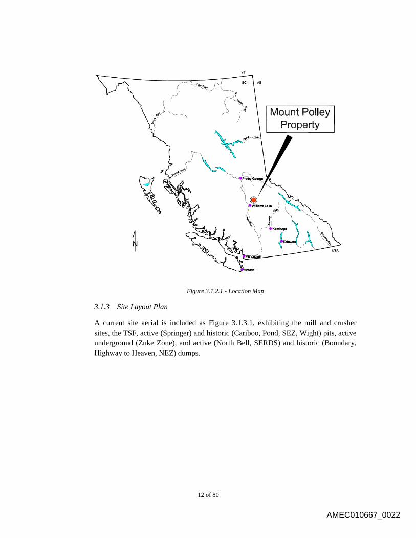
3.1.2 Location
Mount Polley mine is an open pit copper/gold mine located in central British
Columbia (Figure 3.1.2.1), 56 kilometres (km) northeast of Williams Lake (latitude
52 33’ N and longitude 121 38’ W).
AMEC010667_0021
12 of 80
Figure 3.1.2.1 - Location Map
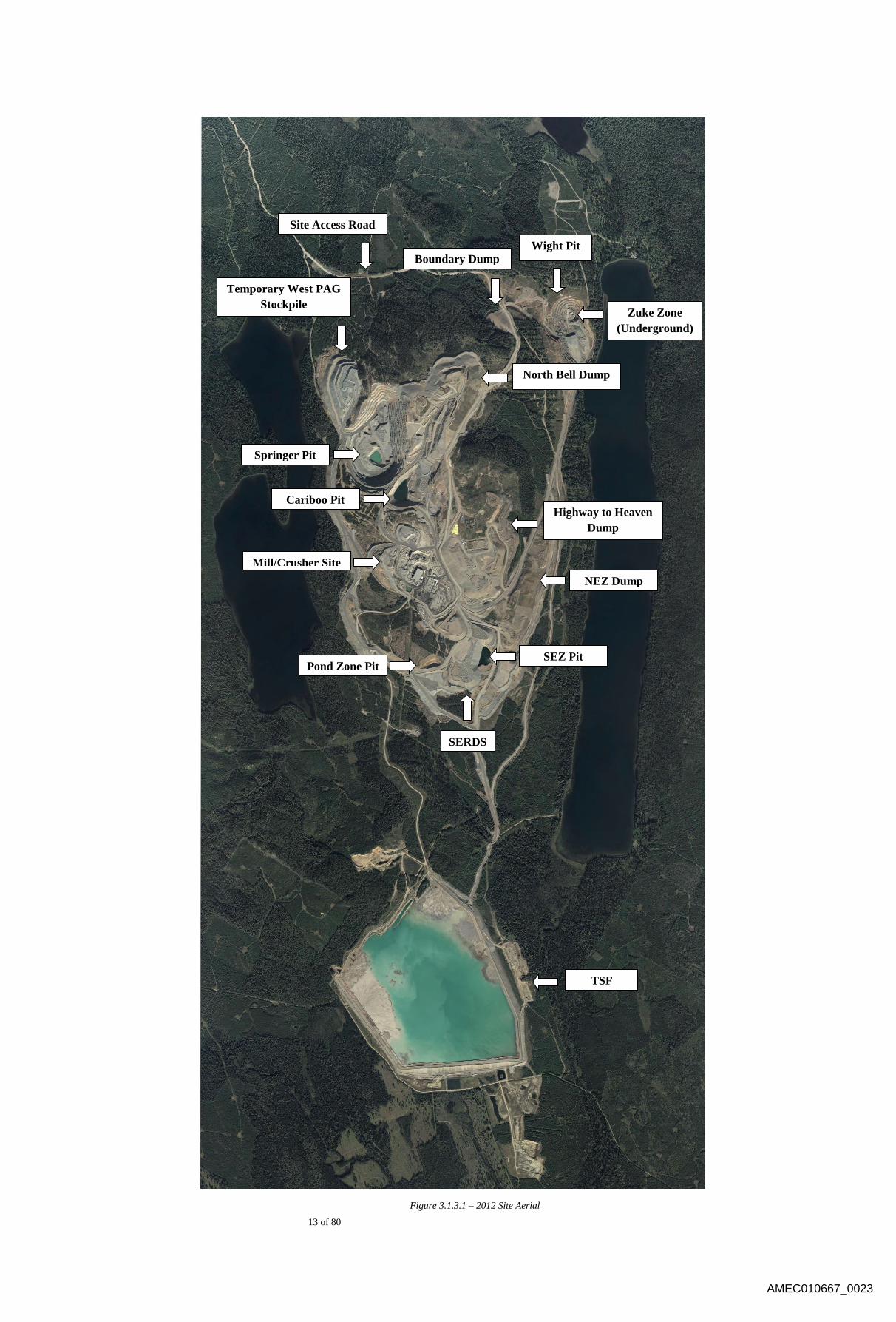
3.1.3 Site Layout Plan
A current site aerial is included as Figure 3.1.3.1, exhibiting the mill and crusher
sites, the TSF, active (Springer) and historic (Cariboo, Pond, SEZ, Wight) pits, active
underground (Zuke Zone), and active (North Bell, SERDS) and historic (Boundary,
Highway to Heaven, NEZ) dumps.
AMEC010667_0022
13 of 80
Figure 3.1.3.1 – 2012 Site Aerial
Wight Pit
TSF
Springer Pit
Cariboo Pit
NEZ Dump
North Bell Dump
Boundary Dump
Pond Zone Pit SEZ Pit
Mill/Crusher Site
Highway to Heaven
Dump
Zuke Zone
(Underground)
SERDS
Temporary West PAG
Stockpile
Site Access Road
AMEC010667_0023
14 of 80
3.1.3.1 Water Management
The TSF was previously operated under a water deficient condition;
meaning more process water was needed than available in the supernatant
pond. This condition changed once the mill started up again in February
2005. The mine is now operating under surplus conditions, which means
there is more water in the system than is required. Therefore, a
combination of careful water management and tailings deposition is
required to maximize the storage potential in the TSF without
compromising the freeboard or embankment stability. All mine-influenced
water is captured and stored in the TSF, while all clean (non-mine-
influenced water) is returned to receiving environments.
Figure 3.1.3.1.1 illustrates the water management systems in place, which
are described in detail in Section 4.1 of this report.
AMEC010667_0024

15 of 80
Figure 3.1.3.1.1 – Water Management Schematic
Geology Wastewater
Mill site
Sump
Joe’s Creek Coffer
Dam and Pipe
SERDS Ditch
Main Embankment Seepage Pond
Pumpback
South Embankment Seepage Pond
Pumpback
Perimeter Embankment Seepage
Pond Pumpback
PAG Ditch
Pit Dewatering
Wight Pit Dewatering
Long Ditch
Perimeter Pond Ditch
TSF Clean Water Ditch
Tailings and Reclaim Water Lines
SEZ Sump
Long Ditch Sump
SERDS
Sump
AMEC010667_0025
16 of 80
3.1.4 Mine Operation History
Construction of the 18,000 tonne per day (tpd) mill feed Mount Polley Mine and
milling facility began in May 1996, and was completed in June 1997. Mining
operations continued until September 2001, at which time operations were suspended
due to low metal prices. In August 2004, Imperial completed a feasibility study which
included an updated ore reserve statement and a new mining plan, and confirmed the
viability of restarting operations at Mount Polley Mine. In October 2004, a mining
permit amendment and a mining lease were granted, and milling operations
commenced in March 2005 and have been in continuous operation since. Ore is
crushed and processed by selective flotation to produce a copper-gold concentrate;
currently, mill throughput is approximately 21,000 tpd.
3.1.5 Mineralization
In general, high grade feed from the Springer pit consists of potassium feldspar and
albite-altered breccias. Copper mineralization occurs mostly as disseminated, veined
and blebby chalcopyrite. Minor bornite and trace quantities of covellite, chalcocite
and digenite are also present. Copper oxides (true oxides, carbonates and silicates) are
present in varying quantities throughout the deposit, depending on the zone.
Malachite/azurite occurs as powdery fracture-fill. Chrysocolla occurs in fractures and
veinlets and as blebs of up to two centimetres (cm), and will only be abundant in the
upper part of the south Springer. Magnetite content within the breccia is expected to
be highly variable depending on location and correlated strongly with copper and
gold grades. High grade (Cu-Au) magnetite ‘pipes’ have not been identified in the
Springer, but may still be found during mining. Drilling in the Springer has located
zones of mineralized, magnetite and garnet-rich calc-silicate alteration. The size and
configuration of the final Springer pit is still under revision as extensions of the
mineralization continue to be discovered at depth and to the northwest. A 73,000
tonne (t) sample of highly oxidized copper mineralization was mined and test milled
from the 1170/60 elevation of the upper south Springer in September 2001. This
sample was used to test the recovery and milling characteristics of this type of high
copper oxide mineralization using the existing mill. The sample had a head grade of
0.37% copper and 0.58 g/t gold, with a 70% copper oxide ratio. The recovery of
copper from this test was only 16.4%, however, the gold recovery was 67.3%,
showing that gold recovery is largely independent from the oxide copper content
[note: copper oxide ratio = copper oxide assay in % / total copper assay in %].
3.1.6 Mining
Mining operations employ standard hard rock mining industry drilling and blasting
techniques prior to loading and hauling to the crushing facilities. Currently,
AMEC010667_0026
17 of 80
operations at Mount Polley mine include the open-pit mining of the Springer pit. The
open-pit loading equipment is a combination of P&H 2100/2300 shovels and loaders,
and the haulage fleet includes Caterpillar 793F and Caterpillar 785C trucks. Various
support equipment is also utilized in the mining operation.
3.1.7 Milling Process
The primary crusher pocket has capacity to accept material from a 150t truck and ore
is processed through a semi-autonomous grinding (SAG)/ball mill circuit producing a
copper/gold concentrate.
In the Mount Polley mill, run-of-mine ore from the open pits is dumped into the feed
pocket of the primary gyratory crusher to reduce the rock to a nominal 200mm. A
hydraulic rock breaker is used to break the oversize material, and the crushed ore is
discharged onto an apron feeder which feeds onto a conveyor to the coarse stockpile.
Ore is reclaimed from underneath the stockpile by four vibrating feeders and
conveyed to a vibrating screen.
In preparation for flotation, ore from the feed stockpile is conveyed to a grinding
circuit, consisting of parallel rod mill/ball mill circuits and a pebble mill circuit;
crusher product is first fed to a rod mill, and then to a ball mill. Ball mill discharge is
pumped to cyclones, where the coarse particles are separated to return to the ball mill,
while the finer particles proceed to the three pebble mills. Cyclones are again used to
return oversize material to the mills, while the fines, now at the necessary size for
mineral separation, are pumped to the flotation circuit.
The flotation circuit separates the valuable minerals from the waste rock, producing a
concentrate. Initial separation is done in a rougher/scavenger circuit, where tailings
flow by gravity to the TSF. Rougher concentrate is further upgraded in a cleaner
circuit to produce the final product. Cleaner tailings are recycled to the
rougher/scavenger circuit.
The concentrate is dewatered in two stages: settling reduces the water content to
roughly 35-40%, while pressure filtration further reduces it to approximately 8%.
Water removed is utilized as process water. Concentrate is stored in the load-out
building and loaded on to 40t trucks for shipping.
3.1.8 Tailings Management
Tailings are deposited as slurry into the TSF. Throughput from the milling process
operates between 900t/h and 1200 t/h, with an average of 920t/hr in 2012. Tailings
are transported to the TSF from the mill via a gravity-flow system of 24” Sclairpipe,
where flow is manipulated for upstream dam construction of Zone U (Sand Cells) and
for beach management.
AMEC010667_0027

18 of 80
Site Conditions 3.2
This section addresses: climate; land surface drainage; hydrology and water quality;
geology, surrounding land use and tenure; and, vegetation and wildlife.
3.2.1 Climate
As a requirement of Effluent Permit PE 11678, meteorology data has been collected
at the mine site, primarily to provide site-specific precipitation and evaporation data
for use in water balance predictions and closure planning.
Mean monthly temperatures range from 13.7°C in July to –10.7°C in January, with a
mean annual temperature of 4.0°C. Prevailing winds are from the northwest in the
winter months and from the south and southwest during the summer months.
Precipitation is well distributed throughout the year, ranging from 600 millimetres
(mm) to 800mm annually (averaging 755mm), with 300mm falling as snow. Detailed
weather information can be obtained from the Annual Environmental and
Reclamation Report.
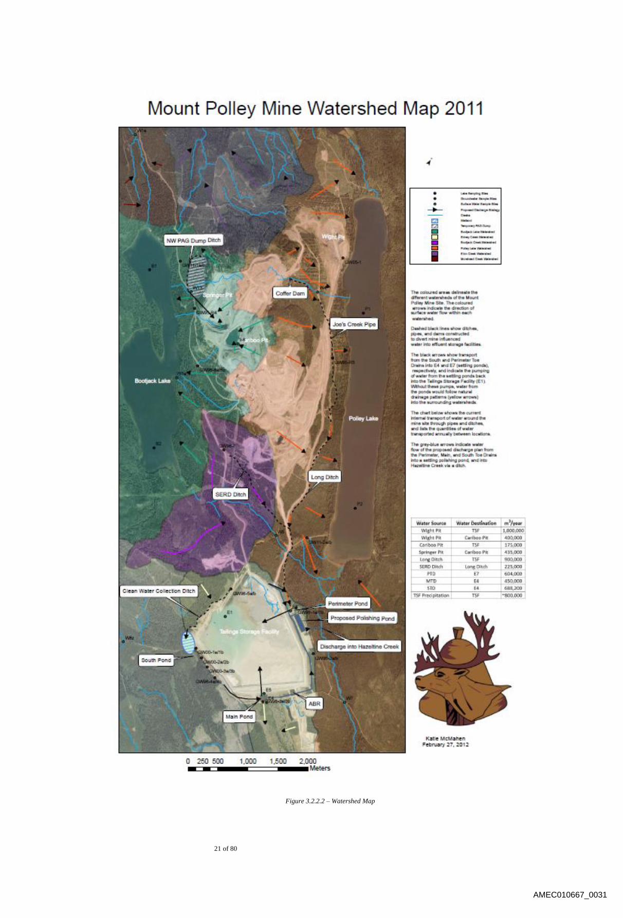
3.2.2 Land Surface Drainage
Mount Polley mine is located near the eastern edge of the Fraser Plateau
physiographic sub-division, which is characterized by rolling topography and
moderate relief. The mine site is situated along a topographic height of land known as
the Mount Polley Ridge which has a maximum elevation of 1266m at the summit of
Mount Polley, and runs northeast to southwest between Polley and Bootjack Lakes,
The drainage system is clustered within the “dogleg” bend of the Quesnel River, west
of Quesnel Lake. Drainage within this system is characterized by the saddle between
the Bootjack and Polley Mountain peaks, which divides the drainage flow into two
generally opposite directions. Approximately 60% of the drainage travels into the
Morehead Lake watershed that empties into the Quesnel River about 20km
downstream of Likely. The remainder drains to the southeast, and enters Quesnel
Lake about 13km upstream of its outlet. Figure 3.2.2.1, while not up to date with
respect to the mine site, provides a good overview of the regional water system.
AMEC010667_0028

19 of 80
Figure 3.2.2.1 – Area Map
AMEC010667_0029

20 of 80
Polley Lake, at an elevation of 926m, has a surface area of about 200ha and drains the
east side of Mount Polley and the west side of the plateau between the Quesnel River
system and Polley Lake. It is drained to the southeast by Hazeltine Creek, which joins
Edney Creek before entering Quesnel Lake. A small tributary of Hazeltine Creek is
Bootjack Creek, which collects the greater part of its water from the south slope of
Mount Polley, downstream of Bootjack Lake. The Southeast Rock Dump Site
(SERDS) is located within this watershed.
In the saddle between Mount Polley and Bootjack Mountain is Bootjack Lake at
elevation of 985m and a surface area of 268ha. Because of its location, some of its
waters had naturally drained to the southeast via Bootjack Creek, but a man-made
diversion now forces its entire content to the northwest into Morehead Lake
(elevation 912m) via Morehead Creek. Morehead Creek has a length of about 2.5km.
Its main tributary is Trio Creek, about 0.75km upstream of the lake. Drainage area of
Morehead Creek above its confluence with Trio Creek is about 14km2. The temporary
West PAG stockpile, C2 Pit, and much of the South Road are located in this
watershed.
A map of these mine site watersheds, as well as constructed water collection and
diversion facilities is included as Figure 3.2.2.2.
AMEC010667_0030
21 of 80
Figure 3.2.2.2 – Watershed Map
AMEC010667_0031

22 of 80
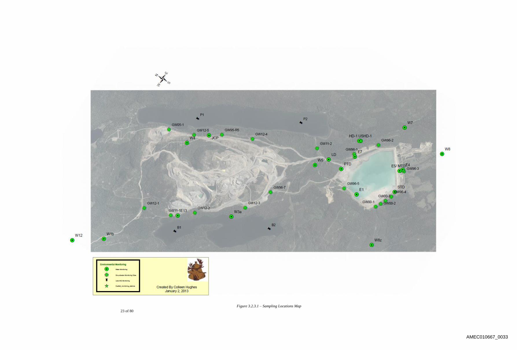
3.2.3 Hydrology and Water Quality
As per permit PE 11678, water quality monitoring is carried out according to the
Surface Water and Groundwater Monitoring Plan developed by MPMC. This plan is
reviewed and updated annually by a Qualified Professional and must be approved by
the Ministry of Environment (MOE). Currently, three (3) single groundwater wells
and fifteen (15) pairs of deep and shallow groundwater wells are monitored, eighteen
(18) surface water sites (five effluent sites and twelve stream sites) and supplemental
surface water locations. A map of these sampling locations is provided in Figure
3.2.3.1. Acute and chronic toxicity testing of the effluent for discharge is also
required under PE 11678.
In conjunction with water sample collection, permit PE 11678 requires hydrological
monitoring at sites W1b (Morehead Creek), W4 (North Dump Creek), W5 (Bootjack
Creek), W7 (Hazeltine Creek), and W12 (6K Creek). Supplemental monitoring is
completed at Edney Creek (W10), the Long Ditch, the SERDS Ditch, Joe’s Creek
Pipe, and the Perimeter and South Toe Drains to provide data for the site water
balance. Data from staff gauge and flow measurements (as well as pressure
transducers at some stations) are used to develop stage-discharge curves for these
locations. Continuous flow data is required at W7 and the effluent discharge outlet.
To further monitor water quantity, the static water level of groundwater wells are
recorded each time they are sampled.
A Biological and Lake Sampling Plan is submitted to the MOE annually as per PE
11678. Lake sampling is completed at two (2) sites in both Polley Lake and Bootjack
Lake, and typically entails: lake profiles of in situ parameters after spring and fall
overturn; surface to bottom water quality samples after spring and fall overturn; and
bi-monthly secchi disk measurements between spring and fall overturn. Biological
monitoring occurs at, but is not limited to, the mine site, Hazeltine Creek, Edney
Creek, Bootjack Lake, and Polley Lake. Monitoring includes documentation of
wildlife occurrences, photo surveys tracking stream productivity, periphyton
chlorophyll a levels, and selenium concentrations in fish tissue and sediment.
Additional monitoring will take place in accordance with the federal Metal Mines
Effluent Regulations (MMER) when mine effluent is being discharged into Hazeltine
Creek. This will include water quality monitoring, toxicity testing, and Biological
monitoring studies which will monitor environmental effects on fish, an invertebrate
species, a plant species and an algal species.
All above information is reported in the Annual Environmental and Reclamation
Report. A full list of sites and coordinates is included in Appendix B.
AMEC010667_0032
23 of 80
Figure 3.2.3.1 – Sampling Locations Map
AMEC010667_0033

24 of 80
3.2.4 Geology
Mount Polley is an alkalic porphyry copper/gold deposit. It lies in the tectono-
stratigraphic Quesnel terrane or Quesnellia, which extends from south of the United
States border to north-central British Columbia. The characteristic component of
Quesnellia is a Middle Triassic to Early Jurassic assemblage of volcanic, sedimentary
and plutonic rocks which formed in an island arc tectonic setting, outboard of the
ancestral North American continental margin in the early Mesozoic. Quesnellia hosts
several major porphyry copper deposits such as Highland Valley, Copper Mountain,
Afton-Ajax and Mount Milligan, all generated by early Mesozoic, calc-alkalic or
alkalic island-arc magmatism.
Mount Polley itself is a complex of intermediate intrusions which were emplaced into
the Triassic sedimentary-volcanic succession in the waning stages of arc magmatism,
near the end of the Triassic (around 205 Ma). Mount Polley lies in the hinge zone of
the regional syncline. The intrusive complex is about six km long (north-northwest)
and three km wide, lying between Polley Lake in the east and Bootjack Lake in the
west. A large nepheline syenite intrusion, the Bootjack Stock, occurs south of Mount
Polley. It is the same age as Mount Polley and is part of the overall intrusive centre,
but is not associated with significant mineralization.
The Mount Polley intrusions are typically monzodiorite, but range from diorite
(oldest) to monzonite (youngest) - not all are porphyritic. They are undersaturated in
silica, and have an alkalic or shoshonitic chemical signature, with quartz being very
rare. Some intrusions are texturally distinct, or form discrete dike-like bodies, but
most of the igneous rocks are compositionally similar, variably altered, and have
indistinct contact relations. In addition to the intrusions, there are zones of polymictic
magmatic-hydrothermal breccias, some of which are related to mineralization events.
These breccias, and some intrusions that are particularly rich in inclusions, have
previously been incorrectly interpreted as volcanic breccias.
Hydrothermal alteration is characterized by potassic (potassium feldspar and locally
biotite), albite and magnetite metasomatism, with zones of garnet or actinolite-rich
calc-silicate. Mineralization and most of the alteration at Mount Polley occurred in
the late stages of igneous activity.
3.2.5 Surrounding Land Use and Tenure
Hunting throughout the region is a common recreational activity as habitats for moose
and deer are common. The mine site is located in MU-2, and access to the site is
prohibited under the Mines and Trespass Act. The project is within the territory of the
guide/outfitter G.M. Elliot of Likely.
AMEC010667_0034
25 of 80
Polley Lake and Bootjack Lake both have forestry recreation sites that are equipped
with boat launches, campsites, toilets, and picnic tables which are used by the public
on a regular basis during the camping and hunting seasons.
3.2.6 Vegetation and Wildlife
Forest cover consists of red cedar, Douglas fir and sub-alpine fir, with lesser black
cottonwood, trembling aspen and paper birch also present. Much of the surrounding
area has been clear-cut by commercial logging.
The baseline wildlife and wildlife habitat assessment for the Mount Polley mine
included all lands and waters that would be directly affected by original mine
development. A buffer zone of 1.5km was also included in the assessment. The
baseline report concluded that the project would cause local alterations in wildlife
habitat, but the alterations would be minor and short term (life of the project).
AMEC010667_0035
26 of 80
4.0 KEY COMPONENTS OF THE FACILITY
Tailings slurry is conveyed from the milling process plant to the TSF via a tailings discharge
pipeline. The tailings are deposited into the impoundment through discharge pipeline on the
embankment crest. Discharge location is controlled through the addition or subtraction of lengths
of pipe in combination with gate systems. When possible, tailings are used to construct sand cells
(an upstream material component of the dam design). A floating reclaim pump recycles process
water from the supernatant pond in the TSF for use in the mill processing circuit. Sediment
ponds and seepage collection ponds are designed to intercept runoff from the surface and
seepage from around the mine site and direct it to the tailings basin. Drains, instrumentation and
monitoring wells are constructed in and around the TSF to assist in monitoring the performance
of the facility. Additional details are available in the reports referenced in Appendix A. As-built
drawings for the latest construction program are included within this Appendix A.
Water Management 4.1
Currently, the total inflow into the TSF from precipitation and surface runoff exceeds
losses from evaporation and storage of water within the voids of deposited tailings. Thus,
MPMC mine site is operating under a net annual water surplus condition, with the
accumulating surplus being stored in the TSF and the Cariboo Pit. MPMC transfers
water as needed between the TSF and the Cariboo Pit.
MPMC maintains a water/mass balance model which is updated on a regular basis with
actual tonnages (milled/mined) and surveyed TSF pond water elevations to maintain the
accuracy of the model and TSF pond level projections.
Wherever possible, clean (non-mine-influenced) water is separated from mine-influenced
water and returned to the surrounding receiving environment.
4.1.1 Mine-Influenced Water Ditch and Sump Systems
Ditch and sump systems are in place such that any and all mine-influenced water is
collected and contained. Some water is reclaimed (recycled) in the milling process,
while all excess mine-influenced water is collected and reports to the TSF.
4.1.1.1 Pit Dewatering
Water is removed from active open pits by blasting and digging sumps
into the bench floor and installing submersible pumps. Water is pumped
from the pits to the Mill, with excess water not used in milling operations
reporting to the TSF.
AMEC010667_0036
27 of 80
4.1.1.2 Northwest PAG Sump and Ditch System
The Northwest PAG Sump and Ditch System collects runoff water from
the Temporary West PAG Stockpile through open gravity-fed ditch flow.
Water is then pumped from the Northwest PAG Sump back into the
Springer Pit; where it is dewatered (along with Pit Water) and reports to
the TSF via the Mill.
4.1.1.3 Mine Drainage Creek Sump
Water from seeps collected along the west side of the property running
parallel to the waste haul road are captured in the Mine Drainage Creek
Sump and pumped to the Mill.
4.1.1.4 Wight Pit Dewatering
Due to the underground operations in the Zuke Zone (a portal into the pit
floor of the once-open-pit operations in the Wight Pit), the Wight Pit is
dewatered. Dewatering of the underground utilizes a pumping system that
transfers the water from the Wight Pit to the Mill.
4.1.1.5 SEZ Sump
The SEZ Sump has been removed from the pumping system.
4.1.1.6 Joe’s Creek Coffer Dam and Pipe
Seepage from the North Bell Dump is collected through a coffer dam
(Joe’s Creek Coffer Dam) and buried gravity-fed pipe system (Joe’s Creek
Pipe), and is transferred across the Wight Pit haul road to the start point of
the Long Ditch.
4.1.1.7 Long Ditch
The Long Ditch is a gravity-fed open ditch system that runs along the east
side of the mine property between the mine disturbance footprint and
Polley Lake. The Long Ditch itself runs from the Wight Pit haul road to
the Long Ditch Sump. After receiving water from Joe’s Creek Pipe and
the Wight Pit, the Long Ditch intercepts various dump and surface runoffs
before being collected in the Long Ditch Sump.
4.1.1.8 Long Ditch Sump
The Long Ditch Sump collects water from the Long Ditch. At the end of
the Long Ditch, prior to entering the sump, water is directed into a gravity-
fed pipe taking the water to the Perimeter Pond Ditch (over Bootjack
AMEC010667_0037
28 of 80
Creek). An overflow structure is in place whereby water exceeding the
design capacity will report to the Long Ditch Sump, from where any water
not captured by the design system is fed into a back-up system consisting
of a second gravity-fed pipe; also reporting to the Perimeter Pond Ditch
(over Bootjack Creek).
4.1.1.9 Orica Ditch
The Orica Ditch runs west-east and is below the Orica explosive storage
site. Water is fed to the SERDS Ditch via a gravity-fed open ditch system.
4.1.1.10 SERDS Ditch
The SERDS Ditch runs west-east and is below the SERDS Dump. Water
is fed to the SERDS Sump via a gravity-fed open ditch system.
4.1.1.11 SERDS Sump
The SERDS Sump is located adjacent (across the haul road) from the
Long Ditch Sump. The SERDS Sump collects water from the SERDS
Ditch and feeds into a gravity-fed pipe. This water is conveyed over
Bootjack Creek to the same Perimeter Pond Ditch system that water from
the Long Ditch Sump reports to. An overflow structure is installed in the
SERDS Sump such that any design overflow will report to the Long Ditch
Sump, to be handled by aforementioned the gravity-fed pipe installed
there.
4.1.1.12 Perimeter Pond Ditch
The Perimeter Pond Ditch receives water from the outflow pipe (and
overflow pipe) from the Long Ditch Sump as well as the SERDS Ditch
and reports through an open gravity-fed ditch system to the Perimeter
Embankment Seepage Collection Pond (PESCP).
4.1.1.13 Mill Site Ditch
The Mill Site Ditch runs around the Northwest side of the Mill Site to the
Southeast Corner; a system complimented by a containment berm
directing water to the Mill Site Sump.
4.1.1.14 Mill Site Sump
The Mill Site Sump is bled into the tailings line and thus directed to the
TSF.
AMEC010667_0038

29 of 80
4.1.1.15 Geology Wastewater
Wastewater from the exploration/geology building is bled into the tailings
line and thus directed to the TSF.
4.1.1.16 TSF Embankment Seepage Ponds
The Main, Perimeter and South Embankment Seepage Collection Ponds
are located at the downstream toe of the Main, Perimeter and South
Embankments respectively. The ponds collect drainage water from the toe
and foundation embankment drains as well as from local runoff.
Additionally, the PESCP collects water from the Long Ditch and SERDS
Ditch systems (as described above). All water collected in these ponds is
pumped back into the TSF basin.
4.1.1.17 Anaerobic Biological Reactor
A 100 gallon per minute (GPM) Anaerobic Biological Reactor (ABR) was
commissioned and constructed at Mount Polley Mine in December 2009.
The objective of this ABR is to passively reduce metal and sulphate
concentrations through biological activity, thereby providing a better
opportunity for meeting water quality discharge requirements. The ABR
feed flow is the Main Toe Drain which collects seepage through the Main
Embankment of the TSF. From the ABR outflow, water passes through a
retention pond before returning to the Main Embankment Seepage
Collection Pond (MESCP), from where it is pumped back into the TSF.
4.1.1.18 Reclaimed Water
The reclaim water line runs adjacent to the tailings line, and transfers
water from the reclaim barge in the TSF Pond through the booster station
and to the mill. Water pumped into the mill building is used as process
water, with the option of directing surplus water to the TSF or to the
Cariboo Pit.
4.1.2 Clean Water Ditch and Sump Systems
Wherever possible, clean (non-mine-influenced) water is separated from mine-
influenced water and returned to the surrounding receiving environment.
4.1.2.1 New Access Road
Clean water to the north and east of the Mine Site is controlled by a series
of under-road culverts and road side ditching along the New Access Road
to ensure the water reports to natural receiving environments.
AMEC010667_0039

30 of 80
4.1.2.2 Joe’s Creek (Clean Water) aka North Dump Creek
Mine-influenced water in this system is collected through the
aforementioned dam and buried pipe system at Joe’s Creek. Clean water
collected below this point flows through an existing drainage towards
Polley Lake – a culvert carrying it under the Wight Pit haul road.
4.1.2.3 TSF Clean Water Ditch (Corner 5 to Corner 4)
Clean water to the west of TSF development is directed away from the
facility and into a small wetland below the South Embankment.
4.1.2.4 Bootjack Creek
Bootjack Creek is a natural creek running west-to-east along the southern
half of the mine property. Bootjack Lake used to flow into the creek, but
no longer does due to the construction of a dam for the Morehead Lake
hydro project. The creek is crossed by mine infrastructure at two
locations: the light-duty vehicle access along the TSF road, and a heavy
duty access along the TSF haul road. A corrugated steel culvert carries the
flow under the light-duty access, and the TSF haul road runs over a man-
made bridge structure called Bootjack Bridge.
4.1.2.5 Corner 5 Clean Water Ditch
A ditch and culvert system exists along the east side of the tailings and
reclaim line ditch between the Mill Site and TSF that collects clean water
and releases it into the natural receiving environment to the northeast of
the TSF.
4.1.2.6 Mill Site (Clean Water)
Clean water to the south of the Mill Site is directed under the waste haul
road by means of two side-by-side corrugated steel culverts, reporting to
Bootjack Lake via the Mine Drainage Creek.
4.1.2.7 Wight Pit (Clean Water)
Clean water to the north and north-east of the Wight Pit is captured by a
series of ditches to stop it entering the pit area and direct it into natural
receiving environments.
AMEC010667_0040

31 of 80
4.1.3 Dust Control Systems
Water is re-used around the Mine Site for dust suppression in dry months (primarily
the summer). Water trucks are used for dust suppression on the haul road network,
and sprinkler systems are utilized for dump watering and water management.
4.1.3.1 Springer Pit Water Filling Station
Water de-watered from the Springer Pit reports to the Springer Pit water
filling station. Water is stored in a large tank and drawn out by mobile
water trucks for application as dust suppression on mine haul roads.
Overflow from the tank is reclaimed to the Mill Site, the excess not used
in the milling process reporting to the TSF.
4.1.3.2 SERDS Water Filling Station
Water is stored in a large tank and drawn out by mobile water trucks for
application as dust suppression on mine haul roads. Overflow from the
tank is reclaimed to the Mill Site, the excess not used in the milling
process reporting to the TSF.
4.1.3.3 Tailings Water Filling Station
Water de-watered from the MESCP can be diverted to the water filling
station. Water is drawn out by mobile water trucks for application as dust
suppression on mine haul roads.
4.1.3.4 TSF Sprinklers
Sprinkler systems are set up along the Perimeter Embankment and Main
Embankment, drawing water from the PESCP and MESCP system
respectively. These systems are used to reduce free water stored in the
TSF by means of applying over vegetated areas.
4.1.3.5 NEZ Dump Sprinklers
Sprinkler systems are set up along the NEZ Dump, drawing from the
Wight Pit De-watering system. This system is used to reduce free water
stored in the TSF by means of applying over reclaimed areas.
4.1.3.6 High Ox Dump Sprinklers
Sprinkler systems are set up along the High Ox Dump, drawing from the
Pit De-watering system. This system is used to reduce free water stored in
the TSF by means of applying over reclaimed areas.
AMEC010667_0041
32 of 80
Tailings Management 4.2
Tailings from the milling process report to the TSF by means of a gravity flow piping
system. The tailings line runs adjacent to the reclaim water line (flowing in the opposite
direction) and runs from the mill, past the booster station, to the TSF.
4.2.1 Tailings Line
The tailings line carries waste material from the milling process from the Mill to the
TSF. The tailings line runs under the waste haul road encased in a multi-plate
structure, continuing in a containment ditch which, in the event of a pipe break, drains
into the TSF. Figure 4.2.1.1 illustrates the orientation of the tailings line.
At the termination of the tailings line as indicated in Figure 4.2.1.1, there exists a
knife gate system that allows flow to be directed to the east or to the south around the
TSF. This is designed such that tailings flow can be manipulated in either direction as
per construction and beach management requirements.
AMEC010667_0042
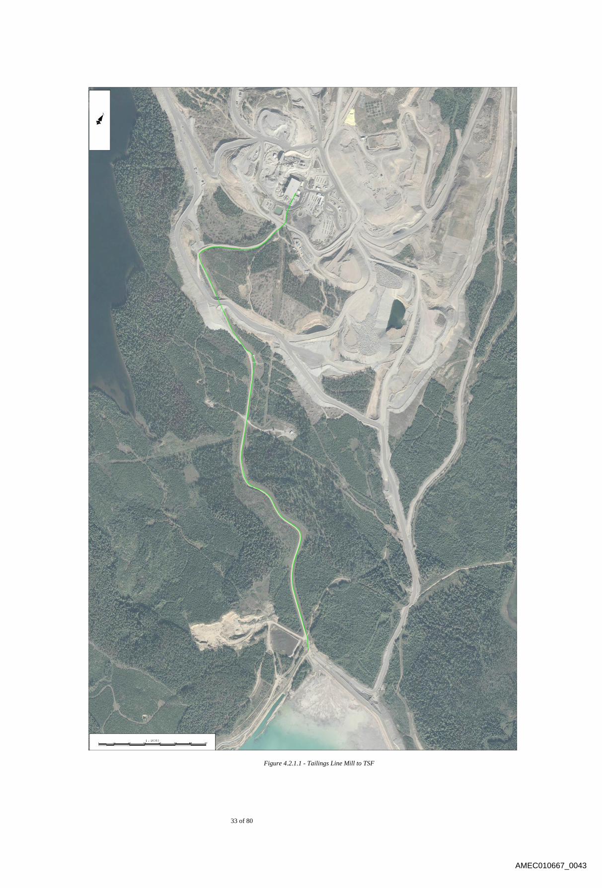
33 of 80
Figure 4.2.1.1 - Tailings Line Mill to TSF
AMEC010667_0043
34 of 80
4.2.2 TSF Facility
The TSF is comprised of one overall embankment that is approximately 4.2km in
length. The embankment, based upon original separate embankments, is subdivided
into three (3) sections; referred to as the Main Embankment, Perimeter Embankment
and South Embankment. Heights vary along the embankment and are approximately
48m, 30m, and 20m respectively (based upon the Main, Perimeter and South
nomenclature).
The design of the TSF is as further described in Section 5.2.
Instrumentation 4.3
The tailings embankment and associated facilities are constructed with instrumentation to
assist in monitoring the facility. The various components are as follows:
Vibrating Wire Piezometers;
Slope Inclinometers; and
Groundwater Monitoring Wells.
The locations of the piezometers and slope inclinometers are on the drawings located in
Appendix C.
4.3.1 Geotechnical Instrumentation
In 2012, additional instrumentation was installed to supplement existing instruments.
Two inclinometers were installed at this time based on the recommendations of the
design consultant.
4.3.1.1 Inclinometers
Overall, ten (10) inclinometers have been installed around the TSF
embankment; seven (7) along the main embankment and three (3) along
the perimeter embankment. Slope inclinometers are installed to measure
the displacement of the embankment. One (1) of the inclinometers has
sustained damage (SI01-01) and is no longer functional.
4.3.1.2 Vibrating Wire Piezometers
Overall, 114 piezometers have been installed around the TSF
embankment. Piezometers have been installed in the TSF embankment
fills, foundations and the impounded tailings upstream of the compacted
till core zone. Currently, 81 of the piezometers are still functioning.
AMEC010667_0044
35 of 80
Geotechnical instrumentation requirements and recommendations are reviewed each
year as part of the As-built Report and Annual Review provided by the design
consultant.
4.3.2 Groundwater Wells
For background information and a location map of groundwater wells, see Section
3.2.3 – Hydrology and Water Quality. There are 37 active groundwater wells at
Mount Polley Mine; Table 4.3.2.1 provides the names and corresponding coordinates
of the wells as illustrated in Figure 3.2.3.1 – Sampling Locations Map.
Groundwater well locations and monitoring are reviewed annually by a Qualified
Professional.
AMEC010667_0045
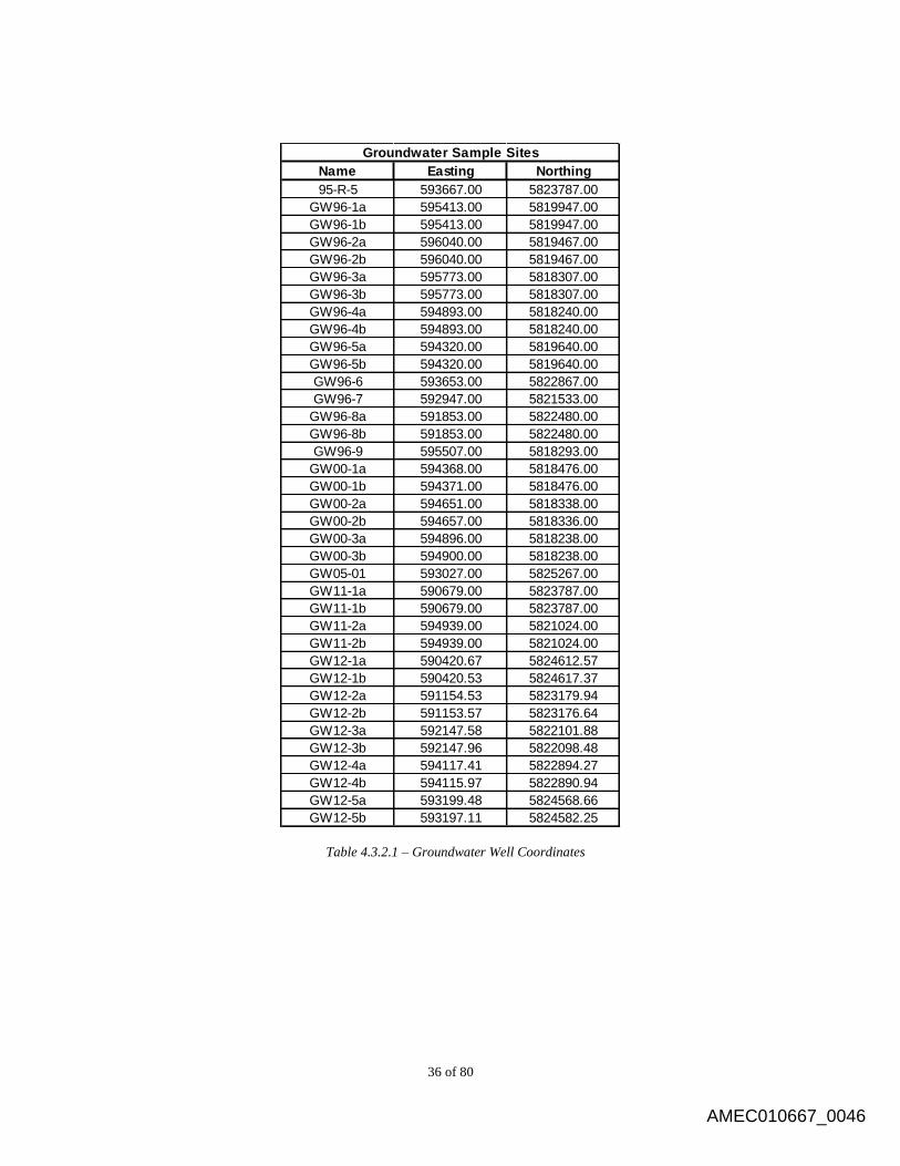
36 of 80
Name Easting Northing
95-R-5 593667.00 5823787.00
GW96-1a 595413.00 5819947.00
GW96-1b 595413.00 5819947.00
GW96-2a 596040.00 5819467.00
GW96-2b 596040.00 5819467.00
GW96-3a 595773.00 5818307.00
GW96-3b 595773.00 5818307.00
GW96-4a 594893.00 5818240.00
GW96-4b 594893.00 5818240.00
GW96-5a 594320.00 5819640.00
GW96-5b 594320.00 5819640.00
GW96-6 593653.00 5822867.00
GW96-7 592947.00 5821533.00
GW96-8a 591853.00 5822480.00
GW96-8b 591853.00 5822480.00
GW96-9 595507.00 5818293.00
GW00-1a 594368.00 5818476.00
GW00-1b 594371.00 5818476.00
GW00-2a 594651.00 5818338.00
GW00-2b 594657.00 5818336.00
GW00-3a 594896.00 5818238.00
GW00-3b 594900.00 5818238.00
GW05-01 593027.00 5825267.00
GW11-1a 590679.00 5823787.00
GW11-1b 590679.00 5823787.00
GW11-2a 594939.00 5821024.00
GW11-2b 594939.00 5821024.00
GW12-1a 590420.67 5824612.57
GW12-1b 590420.53 5824617.37
GW12-2a 591154.53 5823179.94
GW12-2b 591153.57 5823176.64
GW12-3a 592147.58 5822101.88
GW12-3b 592147.96 5822098.48
GW12-4a 594117.41 5822894.27
GW12-4b 594115.97 5822890.94
GW12-5a 593199.48 5824568.66
GW12-5b 593197.11 5824582.25
Groundwater Sample Sites
Table 4.3.2.1 – Groundwater Well Coordinates
AMEC010667_0046
37 of 80
5.0 ENGINEERING AND DESIGN OF COMPONENTS
Water Management 5.1
All water management structures are designed in accordance with the environmental
parameters as set out in MOE-issued permit PE 11678 and MEM-issued Current Permit
M-200.
5.1.1 Mine-Influenced Water Systems
Mine-influenced water ditch and sump systems are designed with best practices at the
time of construction to contain projected volumes of water. Design of all ditch and
sump components interacting with mine-influenced water is revisited each year to
ensure continued suitability given latest available site data and design practices.
5.1.1.1 Pit Dewatering
Water is removed from active open pits by blasting and digging sumps
into the bench floor and installing submersible pumps. Water is pumped
from the pits to the Mill, with excess water not used in milling operations
reporting to the TSF. Pump and pipe selection are varied in order to best
effectively complete the above-described function.
5.1.1.2 Northwest PAG Sump and Ditch System
The existing Northwest ditches currently collect seepage from the
temporary West PAG stockpile located adjacent and along the length of
the NAG stockpile base area. Two open-flow ditches run parallel to the
toe of the dump at a 50m offset, located close to the Springer Pit at the
northwest boundary of the property. The lower ditch, flowing northwest, is
675m in length at an average grade of 7.0%. The upper ditch, flowing
southeast, is 450m in length at an average grade of 7.5%. Both ditches
feed into a third collection sump below the Upper Sump.
From the third sump, water is collected and pumped back into the Pit
Dewatering system by means of a 10” HDPE pipe connected to a grid-
powered 58hp Flygt Pump (with another in parallel as redundancy). Once
in the Springer Pit, the water is collected as part of Pit Dewatering,
described in Section 5.1.1.1.
The upper and lower sumps were constructed to manage potential mine-
influenced water from the Temporary West PAG Stockpile to the east of
the system after construction in 2011 and 2012. In 2013, a larger (third)
sump was brought online in addition to a dedicated power line to feed a
AMEC010667_0047
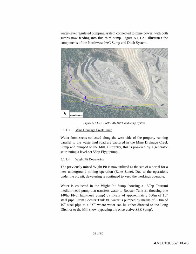
38 of 80
water-level regulated pumping system connected to mine power, with both
sumps now feeding into this third sump. Figure 5.1.1.2.1 illustrates the
components of the Northwest PAG Sump and Ditch System.
Figure 5.1.1.2.1 - NW PAG Ditch and Sump System
5.1.1.3 Mine Drainage Creek Sump
Water from seeps collected along the west side of the property running
parallel to the waste haul road are captured in the Mine Drainage Creek
Sump and pumped to the Mill. Currently, this is powered by a generator
set running a level-set 58hp Flygt pump.
5.1.1.4 Wight Pit Dewatering
The previously mined Wight Pit is now utilized as the site of a portal for a
new underground mining operation (Zuke Zone). Due to the operations
under the old pit, dewatering is continued to keep the workings operable.
Water is collected in the Wight Pit Sump, housing a 150hp Tsurumi
medium-head pump that transfers water to Booster Tank #1 (housing one
140hp Flygt high-head pump) by means of approximately 500m of 10”
steel pipe. From Booster Tank #1, water is pumped by means of 850m of
10” steel pipe to a “Y” where water can be either directed to the Long
Ditch or to the Mill (now bypassing the once-active SEZ Sump).
AMEC010667_0048
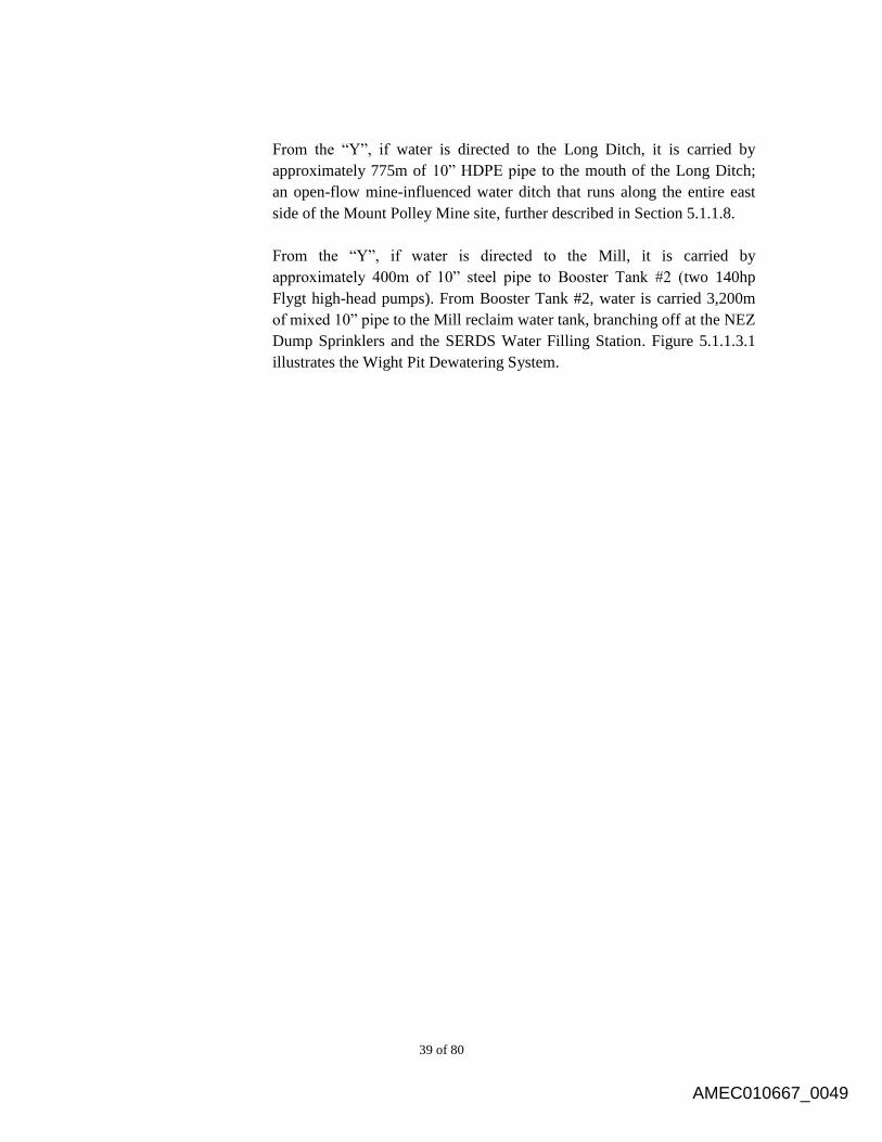
39 of 80
From the “Y”, if water is directed to the Long Ditch, it is carried by
approximately 775m of 10” HDPE pipe to the mouth of the Long Ditch;
an open-flow mine-influenced water ditch that runs along the entire east
side of the Mount Polley Mine site, further described in Section 5.1.1.8.
From the “Y”, if water is directed to the Mill, it is carried by
approximately 400m of 10” steel pipe to Booster Tank #2 (two 140hp
Flygt high-head pumps). From Booster Tank #2, water is carried 3,200m
of mixed 10” pipe to the Mill reclaim water tank, branching off at the NEZ
Dump Sprinklers and the SERDS Water Filling Station. Figure 5.1.1.3.1
illustrates the Wight Pit Dewatering System.
AMEC010667_0049
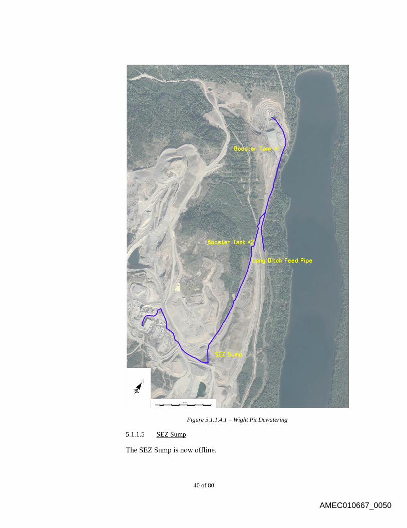
40 of 80
Figure 5.1.1.4.1 – Wight Pit Dewatering
5.1.1.5 SEZ Sump
The SEZ Sump is now offline.
AMEC010667_0050
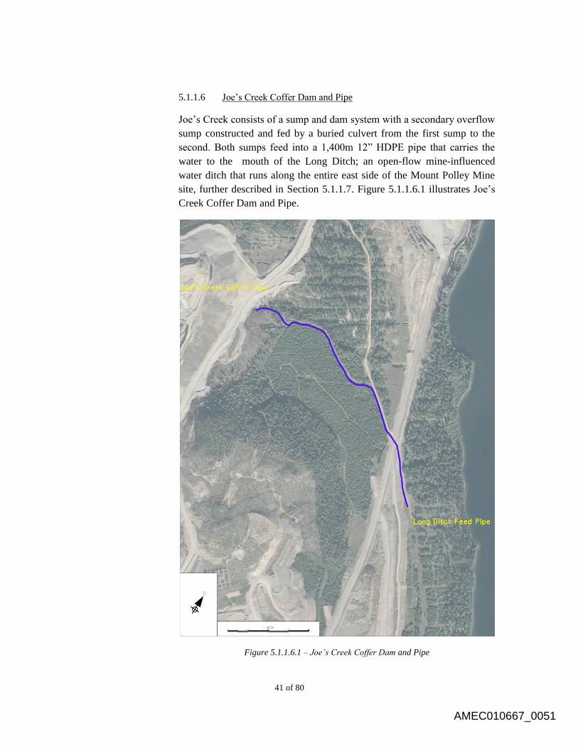
41 of 80
5.1.1.6 Joe’s Creek Coffer Dam and Pipe
Joe’s Creek consists of a sump and dam system with a secondary overflow
sump constructed and fed by a buried culvert from the first sump to the
second. Both sumps feed into a 1,400m 12” HDPE pipe that carries the
water to the mouth of the Long Ditch; an open-flow mine-influenced
water ditch that runs along the entire east side of the Mount Polley Mine
site, further described in Section 5.1.1.7. Figure 5.1.1.6.1 illustrates Joe’s
Creek Coffer Dam and Pipe.
Figure 5.1.1.6.1 – Joe’s Creek Coffer Dam and Pipe
AMEC010667_0051

42 of 80
5.1.1.7 Long Ditch
The Long Ditch collects water from the Wight Pit Dewatering (when
directed so at the “Y” – see Section 5.1.1.4 for further details) and Joe’s
Creek Pipe (see Section 5.1.1.6 for further details) in addition to east-
running run-off from the mine site. The Long Ditch is 3,650m in length
with an average grade of 0.9%, terminating in the Long Ditch Sump.
Figure 5.1.1.7.1 illustrates the Long Ditch System.
Figure 5.1.1.7.1 – Long Ditch
AMEC010667_0052
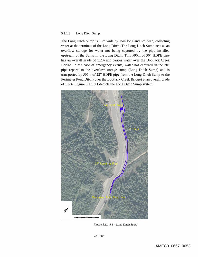
43 of 80
5.1.1.8 Long Ditch Sump
The Long Ditch Sump is 15m wide by 15m long and 6m deep, collecting
water at the terminus of the Long Ditch. The Long Ditch Sump acts as an
overflow storage for water not being captured by the pipe installed
upstream of the Sump in the Long Ditch. This 590m of 30” HDPE pipe
has an overall grade of 1.2% and carries water over the Bootjack Creek
Bridge. In the case of emergency events, water not captured in the 30”
pipe reports to the overflow storage sump (Long Ditch Sump) and is
transported by 505m of 22” HDPE pipe from the Long Ditch Sump to the
Perimeter Pond Ditch (over the Bootjack Creek Bridge) at an overall grade
of 1.6%. Figure 5.1.1.8.1 depicts the Long Ditch Sump system.
Figure 5.1.1.8.1 – Long Ditch Sump
AMEC010667_0053

44 of 80
5.1.1.9 Orica Ditch
The Orica Ditch is a 725m long open-flow gravity ditch with an average
grade of 0.9% that feeds into the SERDS Ditch. Figure 5.1.1.9.1 includes a
depiction of the Orica Ditch.
Figure 5.1.1.9.1 – SERDS Ditch and Sump System
AMEC010667_0054
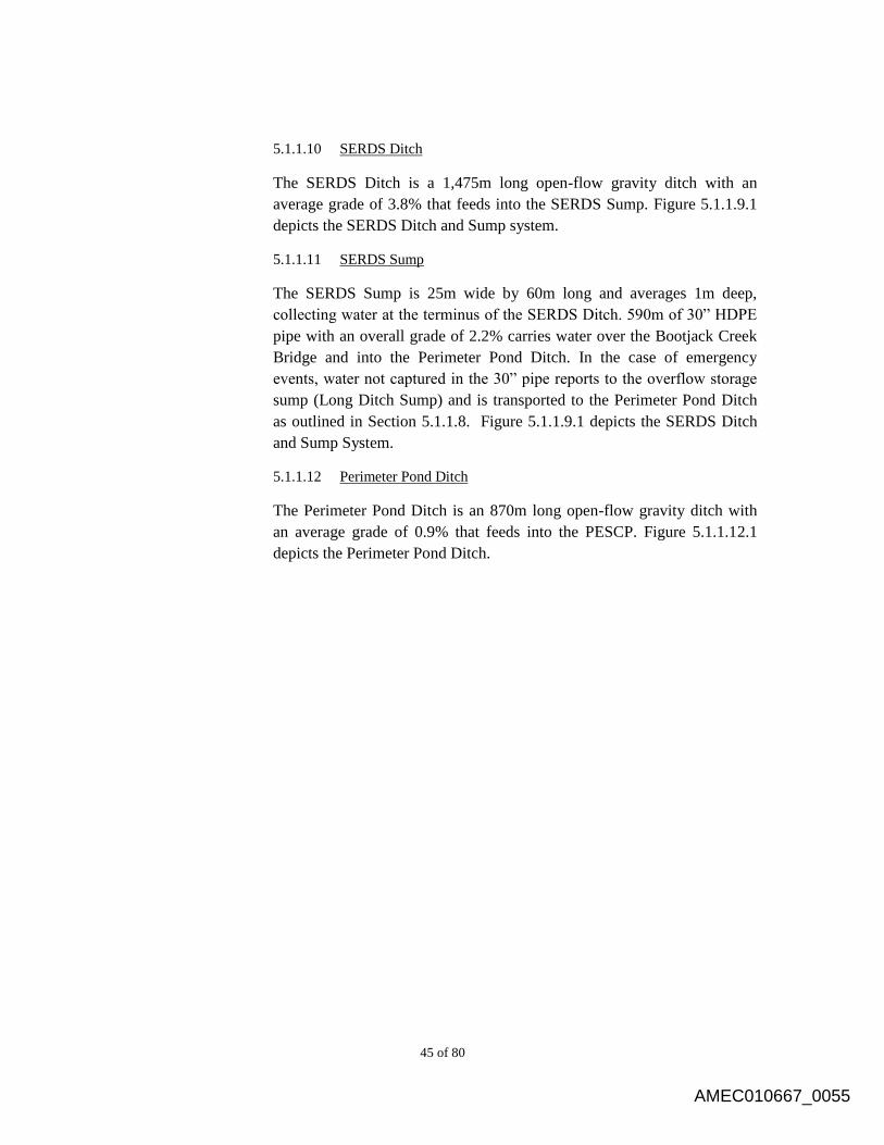
45 of 80
5.1.1.10 SERDS Ditch
The SERDS Ditch is a 1,475m long open-flow gravity ditch with an
average grade of 3.8% that feeds into the SERDS Sump. Figure 5.1.1.9.1
depicts the SERDS Ditch and Sump system.
5.1.1.11 SERDS Sump
The SERDS Sump is 25m wide by 60m long and averages 1m deep,
collecting water at the terminus of the SERDS Ditch. 590m of 30” HDPE
pipe with an overall grade of 2.2% carries water over the Bootjack Creek
Bridge and into the Perimeter Pond Ditch. In the case of emergency
events, water not captured in the 30” pipe reports to the overflow storage
sump (Long Ditch Sump) and is transported to the Perimeter Pond Ditch
as outlined in Section 5.1.1.8. Figure 5.1.1.9.1 depicts the SERDS Ditch
and Sump System.
5.1.1.12 Perimeter Pond Ditch
The Perimeter Pond Ditch is an 870m long open-flow gravity ditch with
an average grade of 0.9% that feeds into the PESCP. Figure 5.1.1.12.1
depicts the Perimeter Pond Ditch.
AMEC010667_0055
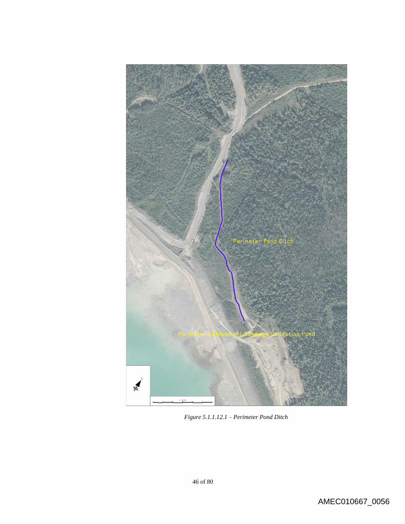
46 of 80
Figure 5.1.1.12.1 – Perimeter Pond Ditch
AMEC010667_0056
47 of 80
5.1.1.13 Mill Site Ditch
The 225m long Mill Site Ditch collects water from around the Mill Site
and directs it into the Mill Site Sump. Figure 5.1.1.13.1 depicts the Mill
Site Sump and Ditch System.
Figure 5.1.1.13.1 – Mill Site Sump and Ditch System
5.1.1.14 Mill Site Sump
The Mill Site Sump is located south of the Mill building. Runoff water
from the mill site area is collected along diversion ditches and directed to
the sump.
The water collected in the sump is either pumped back to the mill or
allowed to flow by gravity to an inlet point (T1) on the tailings pipeline.
Discharge from the manhole is conveyed to the reclaim line in an 8 inch
(200mm) HDPE pipeline. The pipeline is buried through the Mill site area
and runs in the pipe containment channel, where it is connected to the
22 inch DR17 HDPE tailings line via a prefabricated tee in a section of the
pipeline that flows by gravity (non-pressurized flow).
Figure 5.1.1.13.1 depicts the Mill Site Sump and Ditch System.
5.1.1.15 Geology Wastewater
Wastewater from the exploration/geology building is bled into the tailings
line and thus directed to the TSF.
AMEC010667_0057
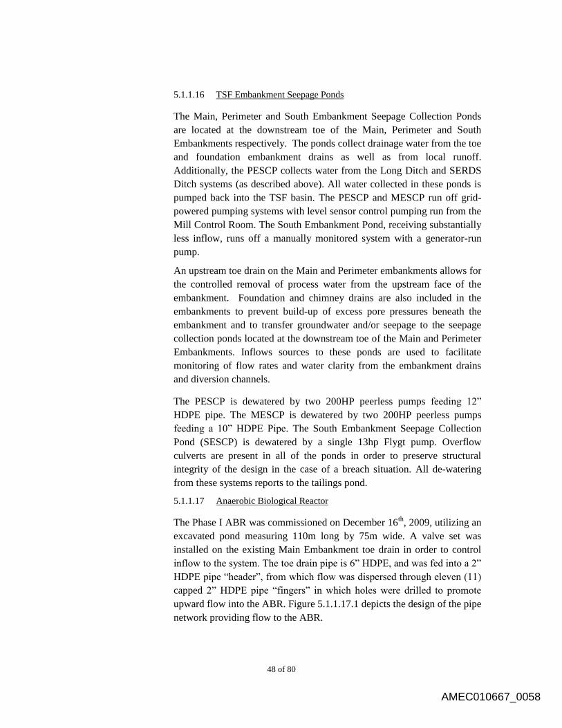
48 of 80
5.1.1.16 TSF Embankment Seepage Ponds
The Main, Perimeter and South Embankment Seepage Collection Ponds
are located at the downstream toe of the Main, Perimeter and South
Embankments respectively. The ponds collect drainage water from the toe
and foundation embankment drains as well as from local runoff.
Additionally, the PESCP collects water from the Long Ditch and SERDS
Ditch systems (as described above). All water collected in these ponds is
pumped back into the TSF basin. The PESCP and MESCP run off grid-
powered pumping systems with level sensor control pumping run from the
Mill Control Room. The South Embankment Pond, receiving substantially
less inflow, runs off a manually monitored system with a generator-run
pump.
An upstream toe drain on the Main and Perimeter embankments allows for
the controlled removal of process water from the upstream face of the
embankment. Foundation and chimney drains are also included in the
embankments to prevent build-up of excess pore pressures beneath the
embankment and to transfer groundwater and/or seepage to the seepage
collection ponds located at the downstream toe of the Main and Perimeter
Embankments. Inflows sources to these ponds are used to facilitate
monitoring of flow rates and water clarity from the embankment drains
and diversion channels.
The PESCP is dewatered by two 200HP peerless pumps feeding 12”
HDPE pipe. The MESCP is dewatered by two 200HP peerless pumps
feeding a 10” HDPE Pipe. The South Embankment Seepage Collection
Pond (SESCP) is dewatered by a single 13hp Flygt pump. Overflow
culverts are present in all of the ponds in order to preserve structural
integrity of the design in the case of a breach situation. All de-watering
from these systems reports to the tailings pond.
5.1.1.17 Anaerobic Biological Reactor
The Phase I ABR was commissioned on December 16th
, 2009, utilizing an
excavated pond measuring 110m long by 75m wide. A valve set was
installed on the existing Main Embankment toe drain in order to control
inflow to the system. The toe drain pipe is 6” HDPE, and was fed into a 2”
HDPE pipe “header”, from which flow was dispersed through eleven (11)
capped 2” HDPE pipe “fingers” in which holes were drilled to promote
upward flow into the ABR. Figure 5.1.1.17.1 depicts the design of the pipe
network providing flow to the ABR.
AMEC010667_0058

49 of 80
Figure 5.1.1.17.1 – ABR Pipe Schematic
The pipes and the bottom of the pond were then covered with an organic
mix (manure and woodchips) and then straw. The organic material was
capped with rock. Figure 5.1.1.17.2 depicts the design organic placement
in the ABR, and Figure 5.1.1.17.3 depicts the placement of the material in
the field.
Figure 5.1.1.17.2 – ABR Organics Schematic
AMEC010667_0059
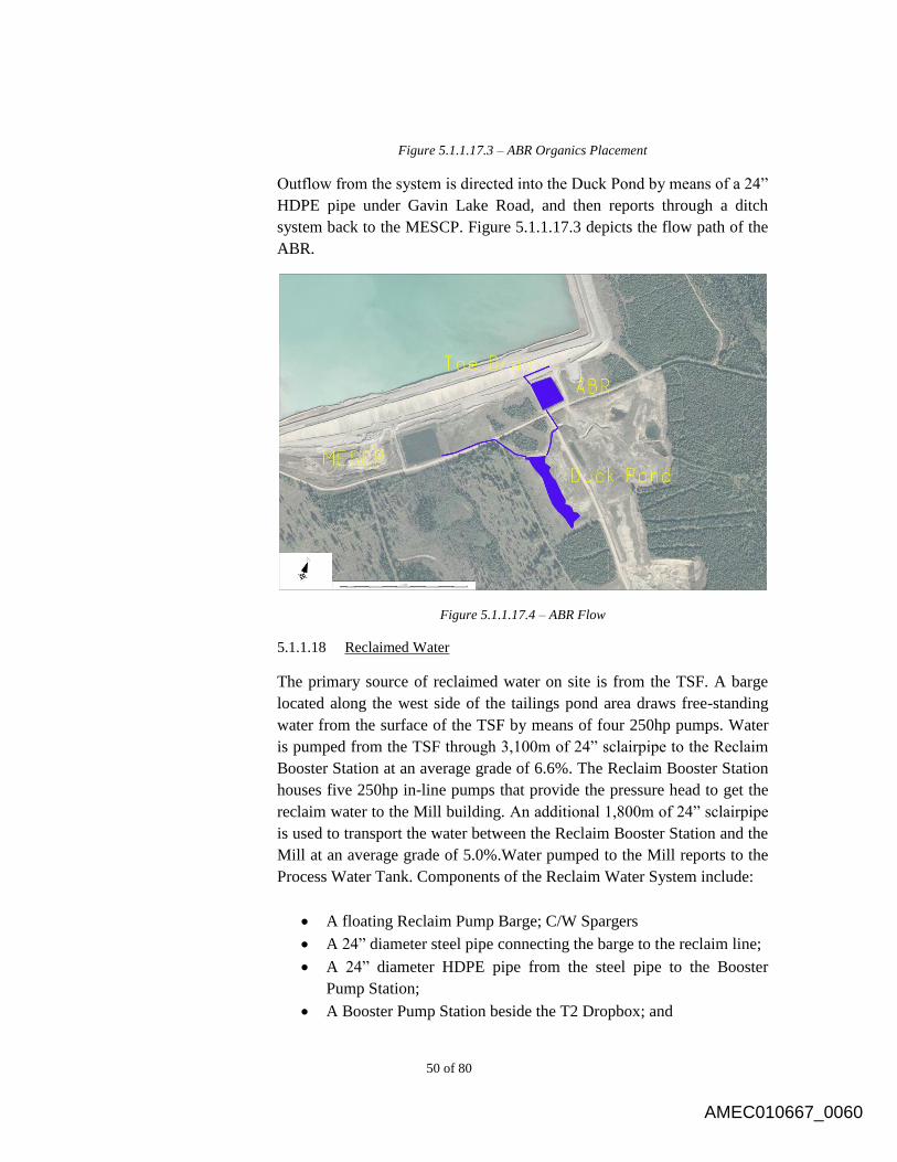
50 of 80
Figure 5.1.1.17.3 – ABR Organics Placement
Outflow from the system is directed into the Duck Pond by means of a 24”
HDPE pipe under Gavin Lake Road, and then reports through a ditch
system back to the MESCP. Figure 5.1.1.17.3 depicts the flow path of the
ABR.
Figure 5.1.1.17.4 – ABR Flow
5.1.1.18 Reclaimed Water
The primary source of reclaimed water on site is from the TSF. A barge
located along the west side of the tailings pond area draws free-standing
water from the surface of the TSF by means of four 250hp pumps. Water
is pumped from the TSF through 3,100m of 24” sclairpipe to the Reclaim
Booster Station at an average grade of 6.6%. The Reclaim Booster Station
houses five 250hp in-line pumps that provide the pressure head to get the
reclaim water to the Mill building. An additional 1,800m of 24” sclairpipe
is used to transport the water between the Reclaim Booster Station and the
Mill at an average grade of 5.0%.Water pumped to the Mill reports to the
Process Water Tank. Components of the Reclaim Water System include:
A floating Reclaim Pump Barge; C/W Spargers
A 24” diameter steel pipe connecting the barge to the reclaim line;
A 24” diameter HDPE pipe from the steel pipe to the Booster
Pump Station;
A Booster Pump Station beside the T2 Dropbox; and
AMEC010667_0060

51 of 80
A 24” diameter HDPE pipe from the Booster Pump Station to the
Mill site.
The reclaim pipeline is located beside the tailings pipeline on the shoulder
of the access road. The pressure rating of the HDPE pipeline decreases as
it approaches the booster pump station and mill site.
The booster pump station is located mid-way along the reclaim pipeline,
beside the T2 Dropbox. Two overflow pipes connect the sump beneath
the pump station to the T2 Dropbox to ensure water will not overflow in
the pump station sump.
Figure 5.1.1.18.1 depicts the components of the Reclaim Water System.
AMEC010667_0061
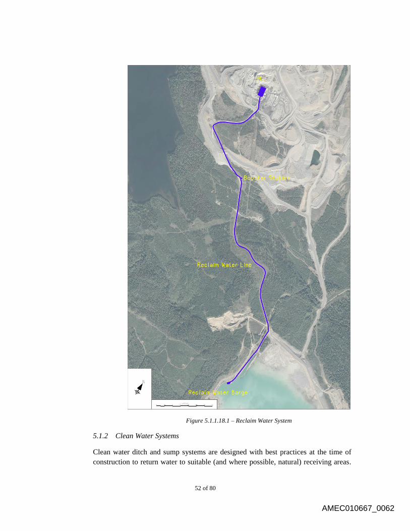
52 of 80
Figure 5.1.1.18.1 – Reclaim Water System
5.1.2 Clean Water Systems
Clean water ditch and sump systems are designed with best practices at the time of
construction to return water to suitable (and where possible, natural) receiving areas.
AMEC010667_0062
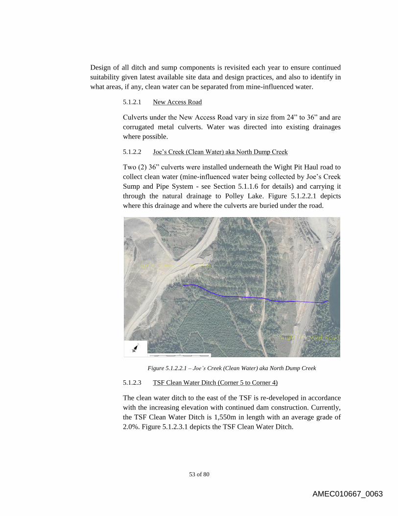
53 of 80
Design of all ditch and sump components is revisited each year to ensure continued
suitability given latest available site data and design practices, and also to identify in
what areas, if any, clean water can be separated from mine-influenced water.
5.1.2.1 New Access Road
Culverts under the New Access Road vary in size from 24” to 36” and are
corrugated metal culverts. Water was directed into existing drainages
where possible.
5.1.2.2 Joe’s Creek (Clean Water) aka North Dump Creek
Two (2) 36” culverts were installed underneath the Wight Pit Haul road to
collect clean water (mine-influenced water being collected by Joe’s Creek
Sump and Pipe System - see Section 5.1.1.6 for details) and carrying it
through the natural drainage to Polley Lake. Figure 5.1.2.2.1 depicts
where this drainage and where the culverts are buried under the road.
Figure 5.1.2.2.1 – Joe’s Creek (Clean Water) aka North Dump Creek
5.1.2.3 TSF Clean Water Ditch (Corner 5 to Corner 4)
The clean water ditch to the east of the TSF is re-developed in accordance
with the increasing elevation with continued dam construction. Currently,
the TSF Clean Water Ditch is 1,550m in length with an average grade of
2.0%. Figure 5.1.2.3.1 depicts the TSF Clean Water Ditch.
AMEC010667_0063
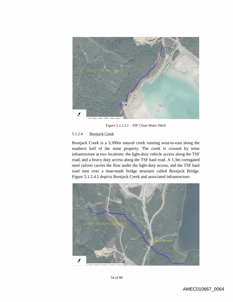
54 of 80
Figure 5.1.2.3.1 – TSF Clean Water Ditch
5.1.2.4 Bootjack Creek
Bootjack Creek is a 3,300m natural creek running west-to-east along the
southern half of the mine property. The creek is crossed by mine
infrastructure at two locations: the light-duty vehicle access along the TSF
road, and a heavy duty access along the TSF haul road. A 1.3m corrugated
steel culvert carries the flow under the light-duty access, and the TSF haul
road runs over a man-made bridge structure called Bootjack Bridge.
Figure 5.1.2.4.1 depicts Bootjack Creek and associated infrastructure.
AMEC010667_0064
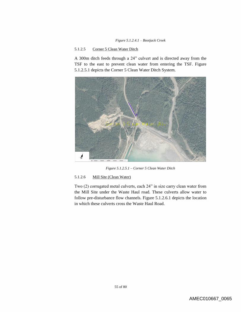
55 of 80
Figure 5.1.2.4.1 – Bootjack Creek
5.1.2.5 Corner 5 Clean Water Ditch
A 300m ditch feeds through a 24” culvert and is directed away from the
TSF to the east to prevent clean water from entering the TSF. Figure
5.1.2.5.1 depicts the Corner 5 Clean Water Ditch System.
Figure 5.1.2.5.1 – Corner 5 Clean Water Ditch
5.1.2.6 Mill Site (Clean Water)
Two (2) corrugated metal culverts, each 24” in size carry clean water from
the Mill Site under the Waste Haul road. These culverts allow water to
follow pre-disturbance flow channels. Figure 5.1.2.6.1 depicts the location
in which these culverts cross the Waste Haul Road.
AMEC010667_0065
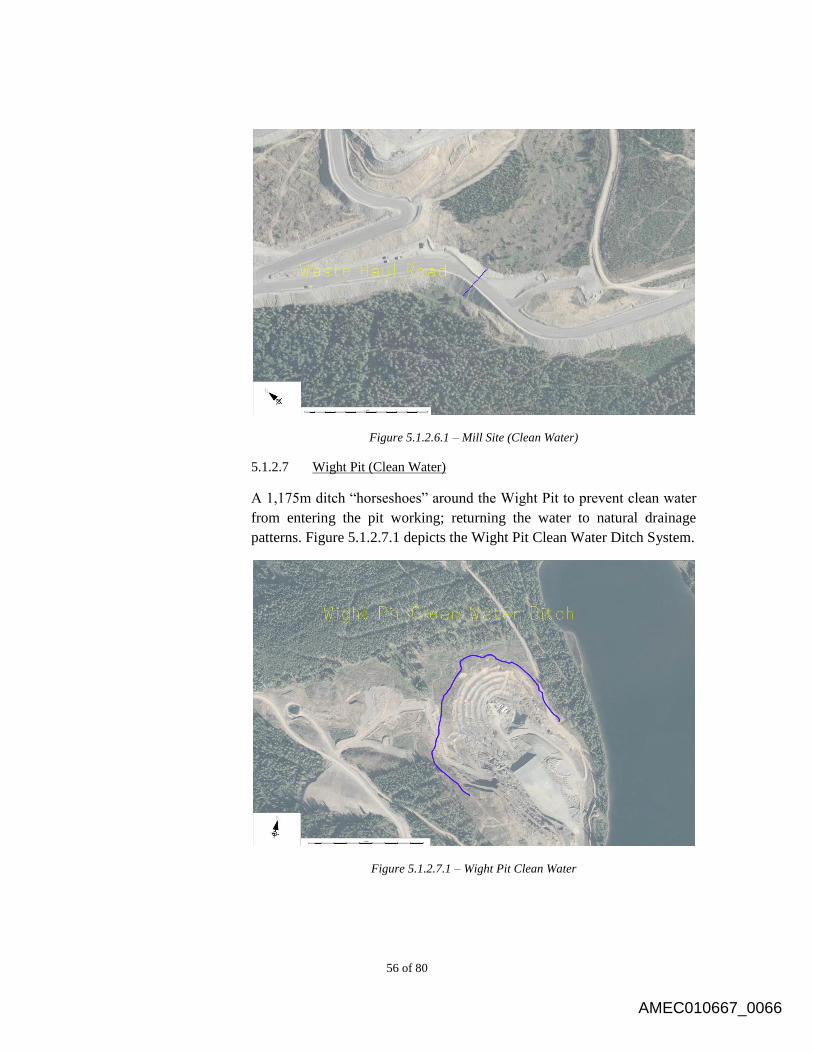
56 of 80
Figure 5.1.2.6.1 – Mill Site (Clean Water)
5.1.2.7 Wight Pit (Clean Water)
A 1,175m ditch “horseshoes” around the Wight Pit to prevent clean water
from entering the pit working; returning the water to natural drainage
patterns. Figure 5.1.2.7.1 depicts the Wight Pit Clean Water Ditch System.
Figure 5.1.2.7.1 – Wight Pit Clean Water
AMEC010667_0066

57 of 80
5.1.3 Dust Control Systems
Dust Control Systems are designed to optimize water recycling and dust suppression
on site. All water used as dust control is captured by existing mine-influence
containment structures.
5.1.3.1 Springer Pit Water Filling Station
The Springer Water Filling Station is designed to provide water to mobile
equipment on site for application as dust suppression.
5.1.3.2 SERDS Water Filling Station
The SERDS Water Filling Station is designed to provide water to mobile
equipment on site for application as dust suppression.
5.1.3.3 Tailings Water Filling Station
The Tailings Water Filling Station is designed to provide water to mobile
equipment on site for application as dust suppression.
5.1.3.4 TSF Sprinklers
TSF Sprinklers are designed to provide water evaporation and dust
suppression on site.
5.1.3.5 NEZ Dump Sprinklers
NEZ Dump Sprinklers are designed to provide water evaporation and dust
suppression on site.
5.1.3.6 High Ox Dump Sprinklers
High Ox Dump Sprinklers are designed to provide water evaporation and
dust suppression on site.
Tailings Management 5.2
Mill tailings are discharged as slurry into the TSF, which has been designed to provide
environmentally secure storage of the solid tailings and supernatant for mill process. As
the solids settle out of the slurry, process fluids are collected and recycled back to the mill
for re-use in the milling process. There is no surface discharge of any process solution
from the TSF. The basis of design must address the following:
Permanent, secure and total confinement of all solid tailings material within a lined
engineered impoundment;
Secure and reliable transportation of the tailings from the mill to the TSF;
AMEC010667_0067
58 of 80
Collection and transport of runoff from waste rock storage areas to the TSF;
Temporary storage of supernatant water on the tailings beach, as required, with
maximum recycling to the mill to produce a zero discharge condition for process
water;
Collection of all free draining liquids from the tailings deposit. Temporary storage
is provided in lined external ponds. The water from the ponds is pumped into the
supernatant pond and recycled to the mill to ensure that no discharge occurs;
Inclusion of monitoring facilities in the TSF to confirm that the design objectives
and operating requirements are being met; and
Staged development of the facility to enable modifications and upgrades to be
implemented based on operating experiences and to distribute the capital
expenditures over the life of the project.
5.2.1 Tailings Line
Tailings slurry is conveyed from the Concentrator through approximately 7,000m of
HDPE pipe to the TSF where it is discharged along the embankment crests. The
pipeline includes the following components:
Two short sections of 30” mm diameter DR 15.5 HDPE pipe included at the
start of the two pipeline sections at the Concentrator;
A 24” mm diameter DR 11 HDPE pipe from the Concentrator to the T2
Dropbox;
The T2 Drop box (not in use);
A Pressure sensor device near the booster station;
A 24” diameter DR 15.5 HDPE pipe from the T2 Drop box to the TSF;
“Y” valve assembly at 5 corners;
A Dump Valve at the start of the Perimeter Embankment & start of the South
Embankment;
Sand cell skids with valve assemblies on the Perimeter & South
Embankments; and
Moveable discharge sections (~100m of 24” HDPE pipe).
The tailings pipeline is located on the shoulder of the access road from the mine.
Tailings slurry is gravity fed to the TSF through the tailings pipeline. The tailings
pipeline has a variable downhill slope that ranges from flat to 8.0% that ensures
drainage.
5.2.2 TSF Facility
The tailings embankment consists of the Main, Perimeter and South Embankments.
The embankments are constructed using zoned earth fill and rock fill and have been
AMEC010667_0068
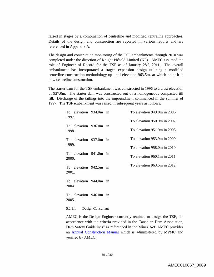
59 of 80
raised in stages by a combination of centreline and modified centreline approaches.
Details of the design and construction are reported in various reports and are
referenced in Appendix A.
The design and construction monitoring of the TSF embankments through 2010 was
completed under the direction of Knight Piésold Limited (KP). AMEC assumed the
role of Engineer of Record for the TSF as of January 28th
, 2011. The overall
embankment has incorporated a staged expansion design utilizing a modified
centerline construction methodology up until elevation 963.5m, at which point it is
now centreline construction.
The starter dam for the TSF embankment was constructed in 1996 to a crest elevation
of 927.0m. The starter dam was constructed out of a homogeneous compacted till
fill. Discharge of the tailings into the impoundment commenced in the summer of
1997. The TSF embankment was raised in subsequent years as follows:
To elevation 934.0m in
1997.
To elevation 936.0m in
1998.
To elevation 937.0m in
1999.
To elevation 941.0m in
2000.
To elevation 942.5m in
2001.
To elevation 944.0m in
2004.
To elevation 946.0m in
2005.
To elevation 949.0m in 2006.
To elevation 950.9m in 2007.
To elevation 951.9m in 2008.
To elevation 953.9m in 2009.
To elevation 958.0m in 2010.
To elevation 960.1m in 2011.
To elevation 963.5m in 2012.
5.2.2.1 Design Consultant
AMEC is the Design Engineer currently retained to design the TSF, “in
accordance with the criteria provided in the Canadian Dam Association,
Dam Safety Guidelines” as referenced in the Mines Act. AMEC provides
an Annual Construction Manual which is administered by MPMC and
verified by AMEC.
AMEC010667_0069
60 of 80
5.2.2.2 As-Built Report/Annual Review
AMEC prepares an As-Built Report and Annual Review summarizing the
construction methodology followed and documenting the as-built dam
conditions for the each construction season. This as-built report is
typically combined with the annual review report. The report provides
confirmation that the dam was raised in conformance with design intent,
and serves as a guide for construction of TSF embankment in subsequent
years.
MPMC marks-up the construction drawings based on as-built surveys of
the raised dam. These marked-up drawings are used by AMEC to produce
CADD as-built drawings for the report.
Instrumentation 5.3
5.3.1 Geotechnical Instrumentation
Geotechnical instrumentation required for the TSF is designed by the Engineer of
Record and operated and maintained by MPMC personnel. Geotechnical
instrumentation suitability is reviewed as part of the annual reporting measures and
recommendations on continued suitability evaluated at this time.
5.3.2 Groundwater Wells
The groundwater wells on site are constructed out of 2” PVC casing (except 95R-5
which has 5” casing). The casing is in a pre-drilled borehole that is 6” in diameter.
The bottom of the casing has an end plug and fits into a steel casing shoe, surrounded
by bentonite chips. The lower portion of the casing is slotted to allow infiltration of
groundwater and is surrounded by filter sand, and separated from other water bearing
horizons by bentonite. The middle portion of the casing is surrounded by a cement-
bentonite grout. The upper portion of the casing is surrounded by sand and/or a layer
of bentonite. Above the ground surface, there is a J-plug in the top of the casing (to
prevent anything from falling in), and it is protected by a stand up metal casing which
is fixed in cement and has a protective locking cap.
The wells are typically installed in pairs of “nested” wells (one shallow, one deep) to
monitor the groundwater at different depths – usually at the first water bearing
horizon in the overburden or bedrock, and a lower one in a water bearing horizon of
the bedrock at a target zone.
AMEC010667_0070
61 of 80
6.0 OPERATION
All operation of water management structures as outlined in this OMS Manual is completed in
accordance with design criteria, regulatory requirements, company policies and sound operating
practices, encompassing all significant aspects of, and activities for, the economical, safe and
environmentally responsible disposal and storage of tailings and management of water.
Water Management 6.1
Currently, MPMC does not discharge any mine-influenced water from site. For this
reason, all systems are designed to, in order of application: separate mine-influenced and
non-mine-influenced water; recycle mine-influenced water in on-site processes; and,
finally, store mine-influenced water in the TSF. All infrastructure in the site water
management in place at Mount Polley mine, as outlined in Section 4.0 and further
detailed in Section 5.0, are designed and operated with this overarching set of priorities.
All water management is completed in accordance with requirements under Permit M-
200 and PE 11678.
The TSF is required to have sufficient live storage capacity for containment of runoff
from the entire contributing catchment area during a 24-hour Probable Maximum
Precipitation (PMP) event. This volume of storm water would result in an incremental
rise in the tailings pond level of approximately 0.39m. The TSF design also incorporates
an allowance of 0.9m of freeboard for wave run-up. Therefore, the normal and maximum
operating pond levels are as follows:
Normal Operating Level – Water level at least 1.3m below the embankment crest;
Maximum Operating Level – Water level is 0.9m below the embankment crest,
which also means the loss of storage capacity for a 24-hour PMP event.
Tailings deposition will cease if the pond level reaches maximum operating level and the
removal of water from the pond will commence using the reclaim barge. The area
downstream of the dam will also be evacuated and access restricted as per the Emergency
Preparedness Plan.
There are no restrictions, with respect to dam safety, on the rate of filling of the
supernatant pond up to the normal operating pond level or rate of emergency draw down
within the pond.
6.1.1 Sump and Ditch Systems
The seepage collection ponds and recycle pumps generally operate without requiring
any external adjustments. However, the following special circumstances require
adjustments to the operating procedures:
AMEC010667_0071
62 of 80
In the event of an emergency that may compromise a water-storage facility,
all diversion ditches that feed the ponds may need to be directed away. Also,
if water quality and permits allow, discharge of water may be possible.
Under freezing conditions, the pumps are operated on a timed pumping cycle
based on site conditions to prevent the pipes from freezing. The pumps will
turn on and off based on the cycle time rather than water level. Once the
temperatures return to normal the pumps can operate under normal conditions.
6.1.2 TSF Embankment Seepage Collection Ponds
As mentioned above, the PESCP is the only of the major (Perimeter, South and Main)
ponds that collects water other than that from the toe and foundation embankment
drains or local runoff. For each of the three, a corrugated steel pipe connects each
pond to a seepage recycle sump where recycle pumps are located. Level sensors in
the PESCP and MESCP control the pumping frequency, while the SESCP is run
based off monitoring height.
Reclaim Barge and Pipeline 6.2
The floating reclaim pump barge is located in the TSF in an excavated channel. The
barge is accessible from land along an access walkway. The floating reclaim pump barge
was designed externally; refer to the manufacturer’s manual for details related to
operations, inspections and maintenance.
The reclaim pipeline does not require any external adjustments during normal operations.
However, during maintenance periods, barge relocation or during a prolonged shutdown
under extreme cold conditions, the reclaim system should be drained via a drain valve
located on the barge.
The Pump Barge and Booster Pump Station may be operated from the Mill control room.
Both pumps may also be operated locally from the barge or pump station to provide
water as required at the Mill site.
Tailings Basin 6.3
The projected rate at which the tailings basin will fill, combined with storage provisions
for make-up and storm water, determine the rate of rise for the embankment. The
anticipated filling schedule and staged construction sequence is shown in Appendix D.
Close monitoring of the pond elevation, depth, area and volume is important for the
following reasons:
AMEC010667_0072

63 of 80
To monitor and maintain required freeboard;
To ensure that there is a sufficient volume of water available as make-up water
while the pond is frozen and precipitation is at a minimum;
To monitor water recoveries;
To enable monitoring of the supernatant pond depth/area/volume so that tailings
characteristics such as dry density can be determined; and
To enable the correlation of the pond level with other data, such as the piezometer
pressures and drain flow quantities.
Adjustments to the basin filling curve may be required due to variation between actual
and projected mill throughput rates, tailings deposition characteristics, water inputs and
outputs and in-situ tailings density. Adjustments to these variables will change the rate of
rise for the tailings and embankments.
Tailings Transport and Deposition 6.4
Tailings are gravity-fed from the mill to the TSF through HDPE pipe. Deposition of
tailings occurs through single-point discharge from this HDPE pipe, and, to the maximum
extent possible, is utilized in “Sand Cell” construction. Mill Operations run at a target of
20,000tpd; with the resulting tailings (and associated water) reporting to the TSF through
the abovementioned system. The operational requirements of tailings deposition are
catered to the design requirements of the Annual Construction Manual.
The objectives of the long-term tailings deposition strategy are to:
Maximize the storage capacity of the facility;
Maintain the supernatant pond in the area of the reclaim barge so as to maximize
the amount of process water available for reclaim;
Provide upstream stability and wave-breaking capacity; and
Establish free draining tailings beaches adjacent to the embankments to facilitate
future embankment raises and to enhance embankment stability.
A staged tailings deposition strategy is currently being implemented by MPMC, and one
of the objectives of this plan is to ensure that tailings solids are deposited along the extent
of all three embankments. The fundamental requirement of the tailings deposition plan is
to ensure that a blanket of tailings solids is present immediately upstream of all
embankments and along the abutments. There is a fundamental objective to establish
beaches adjacent to the embankments, but it is not necessary to continuously maintain a
minimum width of exposed beach adjacent to the embankment, and periodic, temporary
(less than two month duration), shallow flooding (less than 0.5m depth) of the beaches is
anticipated.
AMEC010667_0073
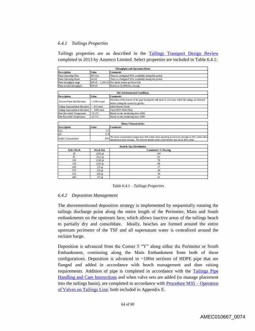
64 of 80
6.4.1 Tailings Properties
Tailings properties are as described in the Tailings Transport Design Review
completed in 2013 by Ausenco Limited. Select properties are included in Table 6.4.1:
Description Value Comments
Plant Operating Time 365 d/yr There is a budgeted 93% availability during this period.
Plant Operating Hours 24 h/d There is a budgeted 93% availability during this period.
Plant throughput range 600 t/h – 1,300 t/h Dry metric tonnes per hour (t/h)
Plant nominal throughput 920 t/h Based on 22,000t/day average
Description Value Comments
Process Plant Site Elevation ~ 1106.0 maslElevation of the bottom of the pipe leaving the mill; there is a box into which the tailings are diverted
before exiting the system by gravity.
Tailings Impoundment Elevation ~ 915 masl Initial (Starter Dam)
Tailings Impoundment Elevation ~ 1000 masl Final (2023 Mine Plan)
Max Recorded Temperature +33.3°C Based on site monitoring since 2006
Min Recorded Temperature -33.7°C Based on site monitoring since 2006
Description Value Comments
S.G. 2.7
pH 11.8
Solids Concentration 36%The slurry concentration ranges from 34% solids when operating at minimum tonnage to 41% solids when
operating at peak tonnage. The nominal design solids concentration was set at 36% solids.
Tyler Mesh Mesh Size Cumulative % Passing
28 (595 µ) 100
65 (212 µ) 91
100 (149 µ) 78
150 (105 µ) 68
200 (74 µ) 57
270 (53 µ) 49
325 (44 µ) 56
400 (37 µ) 41
Throughput and Operation Hours
Site Environmental Conditions
Particle Size Distribution
Slurry Characteristics
Table 6.4.1 – Tailings Properties
6.4.2 Deposition Management
The abovementioned deposition strategy is implemented by sequentially rotating the
tailings discharge point along the entire length of the Perimeter, Main and South
embankments on the upstream face, which allows inactive areas of the tailings beach
to partially dry and consolidate. Ideally, beaches are formed around the entire
upstream perimeter of the TSF and all supernatant water is centralized around the
reclaim barge.
Deposition is advanced from the Corner 5 “Y” along either the Perimeter or South
Embankment, continuing along the Main Embankment from both of these
configurations. Deposition is advanced in ~100m sections of HDPE pipe that are
flanged and added in accordance with beach management and dam raising
requirements. Addition of pipe is completed in accordance with the Tailings Pipe
Handling and Care Instructions and when valve sets are added (to manage placement
into the tailings basin), are completed in accordance with Procedure M35 – Operation
of Valves on Tailings Line; both included in Appendix E.
AMEC010667_0074

65 of 80
6.4.3 Beach Management
Tailings settle in the TSF and form beaches with three distinct slopes. A sandy beach
develops as the coarser tailings fraction settles more rapidly adjacent to the
embankment. The average beach slope above water is about 0.5 percent. As the
tailings flow into the supernatant pond it forms a submerged beach with a slope of one
to two percent. Finer tailings particles are transported further into the supernatant pond
before settling at a slope of about 0.3 percent.
Beach management is based around balancing beach height and advancement around
the TSF, with the goal of established beaches channeling water away from
embankments and towards the TSF Supernatant Reclaim Barge. The allowable
freeboard at the TSF is 1.3m, consisting of a 24-hour PMP event allowance in
addition to a wave-run-up factor. Deposition plans are managed around this freeboard
allowance, and are the responsibility of the Tailings Project Manager, with support
from the Leadership Group. When possible, Sand Cell construction is utilized in order
to maximize the use of tailings material in the construction of design requirements.
The advantages to this are two-fold: the reduction of material required to be imported
to build the upstream (Zone U) component of the TSF; and the reduction of material
being stored in the TSF (as it is being utilized in the structure’s construction). When
Sand Cell construction is not possible, single point-discharge around the TSF is
employed for beach construction.
6.4.4 Sand Cells
Sand Cells are used in satisfying the Zone U (CBL) requirements in the Annual
Construction Manual, and aid in the formation of beach management. Sand Cells are
built in 100m lengths, corresponding to the length of flanged sections of HDPE
tailings pipe. They are 25m-30m wide, as per design constraints, and vary in height
with the beach management requirements (height vs. advancement around dam).
They are constructed by creating a “cell” out of existing tailings and Run-of-Mine
rock with a decant structure at the end of the cell. Tailings are introduced into the cell
by single-point discharge from the tailings line, and allowed to flow through the cell,
the coarser layer being contained in the cell to build Zone U (CBL). This is aided by a
modified bulldozer, which “works” the material in order to optimize the material
retention. The fine or “slimes” fraction then reports to the tailings pond by means of
the decant structure and forms beaches. Management of Sand Cell tailings flow is
completed in accordance with Procedure MO19 – Sand Cell Construction –
Communication Procedure.
Tailings deposited into sand cells and worked by a dozer along the upstream zone
(Zone U) of the tailings embankment are also considered to be 'tailings beach'. One of
AMEC010667_0075

66 of 80
the objectives of the tailings deposition plan currently being implemented by Mount
Polley mine is to allow for sufficient flexibility to enable these sand cells to be
constructed. It is recognized that this deposition strategy may result in short term
flooding of the sandy tailings beaches elsewhere within the impoundment, but that the
depth of flooding along the submerged tailings beaches must be no greater than 0.5m
depth before tailings deposition is re-instated over that section of flooded beach.
6.4.5 Tailings Pipe
The deposition of tailings over the beach in the TSF is accomplished by single point
discharge. Static bypass valves are located at the start of the Perimeter and South
Embankments to allow discharge of tailings during relocation of discharge sections.
A “Y” valve assembly at 5 corners allows for the distribution to the Perimeter/Main
or to the South/Main embankments. Deposition (and beach construction) is controlled
by adding or removing lengths of HDPE pipe along the embankments as required.
The tailings discharge pipeline does not require any external adjustments during
normal operations. The discharge pipeline will drain by gravity to the TSF in the
event of a mill shutdown or power failure. However, the following points must be
remembered during operation of the pipeline:
Never leave all valves closed along the tailings discharge pipeline as they may
be permanently blocked from sanding or suffer damages from excessively
high pressures (refer to Appendix E Procedure M35); and
Ensure that there is an open pathway for tailings to exit before the pipeline is
filled (refer to Appendix E Procedure M35).
Instrumentation 6.5
All instrumentation components must be read regularly. The monitoring frequency for
each is outlined on the schedule in the Annual Construction Manual, as it the schedule by
which data must be collected, plotted and reported. The design engineering firm
(AMEC) must be notified of any anomalous trends. Additional readings and inspections
may also be required after any Unusual Event or Observation, at the request of the
Engineer of Record or Tailings Project Manager.
6.5.1 Geotechnical Instrumentation
Geotechnical instrumentation data is gathered by MPMC personnel in accordance
with the frequencies determined by the design consultant in the Annual Construction
Manual, and submitted to AMEC for review.
AMEC010667_0076

67 of 80
A summary of the existing vibrating wire piezometers and inclinometers is presented
in the Annual Construction Manual with trigger levels, which if exceeded, will
require investigation and possible contingency or remedial actions.
Operation of Geotechnical Instrumentation is completed to satisfy the requirements of
the Annual Construction Manual.
6.5.1.1 Inclinometers
During active construction, the slope inclinometers are to be read, and the
data downloaded and submitted to AMEC Support Engineer, bi-weekly.
During non-active construction the data should be read, downloaded and
submitted monthly. The AMEC Support Engineer shall be responsible for
interpreting and analyzing data collected. Based on dam performance, the
reading frequency may be increased or decreased at the sole discretion of
the AMEC Engineer of Record.
Inclinometer instrumentation is operated in accordance with the
Inclinometer Operation Manual and collected data is provided to the
design consultant in accordance with the Annual Construction Manual.
6.5.1.2 Vibrating Wire Piezometers
During active construction, piezometers are to be read, recorded, and
submitted to the AMEC Support Engineer bi-weekly. The MPMC Field
Inspector shall indicate on these plots when construction activities have
taken place within 100m of S.O.L chainage from the piezometers. This is
required so that changes in piezometric pressures and measured
displacements can be correlated with construction activities. During non-
active construction the data should be read, recorded, and submitted
monthly. The AMEC Support Engineer shall be responsible for
interpreting and analyzing data collected. Based on dam performance, the
reading frequency may be increased or decreased at the sole discretion of
the AMEC Senior Geotechnical Engineer.
Inclinometer instrumentation is operated in accordance with the
Piezometer Operation Manual and collected data is provided to the Design
Engineer in accordance with the Annual Construction Manual. Data may
be entered on the Piezometer Data Sheet, included for reference in
Appendix E.
Geotechnical instrumentation operational requirements and recommendations are
reviewed each year as part of the As-built Report and Annual Review provided by the
design consultant.
AMEC010667_0077
68 of 80
6.5.2 Groundwater Wells
MPMC has a Quality Assurance/Quality Control (QA/QC) Manual, which is required
under Effluent Permit 11678 issued by the MOE under the Environmental
Management Act. This manual was last updated on January 31, 2013.
The QA/QC Manual includes a Groundwater Well Standard Operating Procedure and
Groundwater Well Work Method for the operation of groundwater wells at Mount
Polley Mine; all are included for reference in Appendix E.
AMEC010667_0078

69 of 80
7.0 MAINTENANCE AND SURVEILLANCE
As outlined in this document, water management on site is comprised of several components and
associated facilities. These components and facilities must be inspected and maintained
regularly to ensure that any changes to the TSF conditions, performance, or a potentially
hazardous condition can be identified and promptly addressed.
General 7.1
The Mill Maintenance Superintendent is responsible for ensuring that surveillance is
carried out regularly. The Mill Maintenance Superintendent is responsible for daily
management of the TSF water management systems and directs an operating crew to
carry out routine activities. The Tailings Project Manager is responsible for directing and
co-ordinating all TSF construction to the specifications of the design engineering firm
retained. A list of site personnel and associated responsibilities are provided in Table 2.1.
The Tailings Project Manager will conduct a Dam Surveillance walkover at least once
per quarter. All Dam Surveillance reports should be reviewed by the Mill Maintenance
Superintendent and filed at the Mount Polley Mine Site. Additional (non-routine),
documented “drive-bys” of the TSF and associated facilities will be required following
extreme or unusual events, The Mine Operation Manager must be made aware of any
unusual events or observations, and must contact the Engineer of Record as required.
Typical examples of unusual events and observations to be made during such walkovers
are outlined in Unusual Events and Actions, included in Appendix E.
An Inspection Log is provided in Appendix E to help guide the observation and
surveillance process. The inspection log covers major items related to the TSF and
associated facilities. Additional details are provided in the following sections.
Water Management Systems 7.2
The seepage collection ponds and recycle pumps shall be inspected, by the surface crew,
according to the schedule outlined in the Inspection Schedule and an Inspection Log
completed as provided in Appendix E. Typical observations to be made during
surveillance are as follows:
Water levels in collection ponds;
Pump back flow rates from pumps;
Evidence indicating seepage from the collection ponds;
Evidence indicating erosion or instability on the slopes of the ponds;
The overflow culverts and pipelines between the monitoring sumps and recycle
sumps are free of any obstructions; and
AMEC010667_0079
70 of 80
Ensuring that the discharge end of the seepage recycle pipeline isn’t submerged in
tailings.
Additional observations will also be required under special circumstances as follows:
Monitor the pumping from ponds during freezing conditions to ensure that the
pumping cycle is adequate at keeping the pipes from freezing and in keeping the
pond level constant; and
Monitor the water quality in the ponds during spring freshet to ensure that the
seepage water from the TSF is at acceptable levels if water permits allow for
discharge.
The Unusual Events and Actions document identifies additional events and circumstances
that will require increased observations and documentation.
Tailings Pond 7.3
The pond level must be at least 1.3m below the crest elevation under normal operating
conditions. Emergency procedures, discussed in Section 9.0, must be followed if the
pond reaches the maximum operating level. Regular inspections of the pond level must
be carried out according to the schedule outlined in the Inspection Schedule. An
Inspection Log is provided in Appendix E.
Additional pond level inspections are required after an Unusual Event; additional
observations will need to be documented.
Tailings Embankment 7.4
Regular surveillance of the embankments and associated structures should follow the
schedule outlined in the Inspection Schedule. An Inspection Log is provided in
Appendix E. Typical observations to be made during surveillance include:
Evidence indicating dam structure deformation (e.g. slope bulging, tension cracks
on the crest or crest settlement);
Evidence indicating seepage, runoff or erosion;
Clarity and quantity (visual estimate) of seepage water entering the seepage
collection sumps;
Possible evidence indicating piping downstream of the embankments; and
Other unusual conditions in the TSF area.
The embankment and associated structures do not require regular maintenance; however,
specific maintenance items may be identified as a result of regular observations and
surveillance of the embankment.
AMEC010667_0080

71 of 80
The Unusual Events and Actions document outlines additional observations that will
need to be documented after any unusual event.
Tailings Discharge Pipeline 7.5
The tailings discharge pipeline will be inspected and maintained regularly to ensure that
the system operates properly. The Inspection Schedule provides a schedule for regular
surveillance of the pipeline. An Inspection Log is provided in Appendix E. Typical
observations to be made during surveillance include:
Locations of external excessive wear or damage of the pipeline;
Evidence indicating leakage from the pipeline; and
Ensuring a constant grade of all pipelines leading onto the embankments,
maintaining a proper flow, to prevent sanding up or freezing of the lines.
A Mill Operations Daily Tailings Checklist is included in Appendix E
The Unusual Events and Actions document outlines additional observations that will
need to be documented after any unusual event. Repairs to the discharge pipeline,
dropbox and/or discharge sections may be required after any such unusual event.
Reclaim Pipeline 7.6
The reclaim pipeline, pump barge and booster pump station shall be inspected according
to the Inspection Schedule and an Inspection Log completed as provided in Appendix E.
Typical areas to inspect during surveillance of the reclaim pipeline include:
Locations of excessive wear of the pipeline (filed with maintenance department);
Evidence indicating leakage from the pipeline;
Monitoring of the TSF Pond and Barge elevations to ensure that a gradient is
maintained in the steel pipe. The barge ramp may need to be relocated higher or a
new channel excavated for the re location of the barge;
The de-icing system for the pump barge should be checked to ensure that it is
working prior to freezing conditions; and
Additional inspections are required after any unusual event. The Unusual Events and
Actions document outlines additional observations that will need to be documented.
Repairs to the reclaim pipeline, barge and/or pump station may be required after any such
unusual event.
AMEC010667_0081
72 of 80
Instrumentation 7.7
7.7.1 Geotechnical Instrumentation
Generally, the instruments do not require regular maintenance but may require
occasional maintenance as follows:
The piezometer wires may need to be extended as construction continues;
The piezometer wires may need to be cut and re-attached if the readout box is
unable to acquire any data;
Piezometer wires that are exposed may become corroded and may need to be
trimmed until a fresh surface is exposed to allow readings to be taken;
Piezometer units are to be covered in crush to mark and protect their
locations; and
All instrumentation areas should be clear of large rocks and debris.
7.7.2 Groundwater Wells
Decommissioning and replacement of existing groundwater wells and construction of
groundwater wells at new monitoring locations are addressed by a third party
Qualified Person in a site groundwater assessment which is completed every five (5)
years, as required by permits.
Well development is completed as soon as possible after installation of new wells,
and is completed on any wells where water being purged contains significant amounts
of sediment (the presence of sediment is noted in sampling observations).
During bi-annual sampling, any wells missing PVC J-pugs, casing protector lids, or
locks are noted and fixed.
AMEC010667_0082

73 of 80
8.0 DOCUMENTATION
Design Consultant As-Built Report 8.1
Annual Inspections of the tailings impoundment and associated facilities are required to
evaluate the current and past performance of the facility and to observe potential
deficiencies in its condition, performance and/or operation. The Environmental
Superintendent is responsible for arranging the inspections. This level of dam safety
evaluation should be based on detailed observations made by the Engineer of Record on
site and the relevant information on the TSF operations collected by site personnel.
Additional reviews may be required also as a follow up to the report of an unusual event
or observation.
The Environmental Superintendent or designate should accompany the Engineer of
Record during the annual inspection. The Engineer of Record will evaluate the safety of
the TSF and incorporate a routine review of the following:
The consequences classification of the dam;
The operations and maintenance manual;
The availability of all documents pertaining to dam safety on site;
The site surveillance practice; and
Changes in relevant regulatory requirements since the last inspection.
The Engineer of Record will issue an annual inspection report after completing the
review. The report will include the following:
Conclusions on the status of the TSF;
Statements indicating completion of recommendations from previous inspections
and reviews; and
Recommendations, if necessary.
The General Manager and the MEMRH should review each annual inspection report.
Copies of the reports should be made available on site and are available in the office of
the Engineer of Record. The General Manager should prepare and execute an appropriate
action plan to ensure that all recommendations made in the annual inspection report are
followed. This action plan should be documented.
The design consultant’s as-built report will also outline any modifications made in the
field to the initial methods of foundation preparation; borrow soils excavation, hauling,
placement, and compaction; or other relevant work. Documentation of any such
refinements made during construction will be of benefit for subsequent embankment
raises. The as-built report will also include recommendations pertinent to the
construction and QA/QC monitoring of future construction.
AMEC010667_0083
74 of 80
Dam Safety Review 8.2
The principle objective of a Dam Safety review (DSR) is to ascertain that a dam has an
adequate margin of safety, based on the current engineering practice and updated design
input data. A DSR may also be carried out to address a specific problem.
A qualified engineer will be responsible for conducting each DSR at the TSF. The
engineer conducting the DSR must be qualified to conduct safety evaluations and be
familiar with the designs and other site-specific conditions and requirements pertaining to
operations of the impoundment and associated facilities; but ideally should not have been
involved in the design, construction or operation of the TSF.
Routine DSR’s at the TSF will be scheduled, confirmed or revised at the time of each
annual inspection. The next DSR for the TSF is scheduled for 2016.
A detailed scope of work for each DSR will be defined by the engineer prior to
conducting the review, and be consistent with current engineering practice at the time it is
conducted. Each DSR will evaluate the safety of the TSF and incorporate a detailed
review of the following:
The consequences classification of the dam;
The adequacy of past annual inspection practice, the annual inspection
recommendations, and their implementation;
The Operation and Maintenance Manual; and
Timing for the next regular DSR.
Each DSR report should include conclusions and, if necessary, recommendations
pertaining to the safety of the TSF. Copies of the DSR will be sent to the Environmental
Superintendent and the MEMRH for review. Similar to the annual inspection report, an
action plan should be prepared by the Environmental Superintendent to address the DSR
recommendations. A copy of each report will be sent to the MEMRH and will also be
available at the site and at the office of the Engineer of Record.
AMEC010667_0084
75 of 80
9.0 EMERGENCY PROCEDURES
All operation of water management structures as outlined in this Operation, Maintenance and
Surveillance Manual, including that relating to emergency procedures, is completed in
accordance with regulatory requirements, company policies and sound operating practices,
encompassing all significant aspects of, and activities for, the economical, safe and
environmentally responsible disposal and storage of tailings and management of water.
General 9.1
This Emergency Preparedness and Response Plan will enable Mount Polley mine to
identify emergency and hazardous conditions threatening the TSF, expedite effective
response actions to prevent failure, and reduce loss of life and property damage should
failure occur.
In the event that Mount Polley mine is unable to comply with any of the terms and
conditions of the permit, due to any cause, Mount Polley mine will:
1. Immediately notify the MEM of the failure to comply;
2. Immediately take action to stop, contain, and clean up unauthorized
discharges or otherwise stop the non-compliance, correct the problem, and if
applicable, repeat sampling and analysis of any non-compliance immediately;
and,
3. Submit a detailed written report to the MEMRH within thirty (30) days (five
days for upsets and bypasses), unless requested earlier by the MEMRH. The
report will contain a description of the non-compliance, including exact dates
and times, if the non-compliance has not been corrected, the anticipated time
it is expected to continue, and the steps taken or planned to reduce, eliminate,
and prevent reoccurrence of the non-compliance.
Warning Signs 9.2
Three levels of emergency conditions (or warning signs) can be identified with respect to
the site operations. These are defined as follows:
9.2.1 Level 1
Unusual conditions that do not yet represent a potential emergency, but do require
prompt investigation and resolution.
AMEC010667_0085
76 of 80
9.2.2 Level 2
Conditions that represent a potential emergency, if sustained or allowed to progress,
but no emergency situation is imminent.
9.2.3 Level 3
An emergency defined by either failure of a significant component of the TSF and/or
associated facility or a significant failure of the performance of a component of the
TSF. Such failure may have already occurred, or be imminent.
Situations 9.3
Typical situations that would be classified under the three levels of emergency conditions
(Level 1, 2 or 3) and the actions to be taken are outlined in Emergency Levels (included
in Appendix E) and described below:
9.3.1 Level 1 Situation
The action in the event of a Level 1 Emergency Condition will typically involve an
investigation, intensified monitoring, inspecting and/or testing, and defining and
implementing possible corrective measures.
Construction equipment will be available at the mine and include, but not be limited
to, an excavator, a grader, haul trucks and a bulldozer. Material will be available both
at the TSF and at the mine for use in repairing or remediation of any damaged areas.
9.3.2 Level 2 Situation
The first action in the event of a Level 2 Emergency Condition is to discuss and
define an action plan, at the site, under the direction of the Environmental
Superintendent. After such a plan is prepared, it must be presented to the Mine
Manager for approval. Construction equipment should be made available, if required,
at short notice.
9.3.3 Level 3 Situation
The first actions in the event of any Level 3 Emergency Condition are:
Check that all persons who could possibly be affected are safe; and
Initiate the appropriate chain of communications.
The person who initiated the communication should then stand-by at a safe location
near the problem area and await further instructions or decisions. All those involved
in emergency response, after first having communicated with the appropriate parties,
AMEC010667_0086
77 of 80
should consider two types of actions as first steps in the emergency response, with
respect to the protection of human life and health, environment and property:
What can be done to prevent the situation from worsening?
What can be done to reduce the consequences of the impending or actual
failure?
Any such action must be presented to the Mine Manager who will decide on its
implementation in consultation with the MEMRH.
Incident Notification Procedures 9.4
The following incident notification procedures are to be followed for all emergency
conditions.
9.4.1 Level 1 and Level 2
The notification procedures are as follows:
The person first noticing a Level 1 or Level 2 Emergency Condition shall
notify the General Manager and initiate corrective actions and intensified
monitoring.
The General Manager shall notify the Engineer of Record as appropriate.
9.4.2 Level 3
The notification procedure for a Level 3 Emergency Condition is as follows:
The person noticing a Level 3 Emergency Condition shall notify the General
Manager and initiate corrective actions and/or intensified monitoring, as
appropriate.
The General Manager shall notify Mount Polley Corporate office, Mount
Polley Tailings Project Manager, and the Engineer of Record.
In the event of an emergency situation that will result in an actual or potentially
imminent dam failure, or release of untreated water, the General Manager shall also
notify the MEMRH.
Names and telephone numbers for the key contacts are given in Table 2.1
AMEC010667_0087
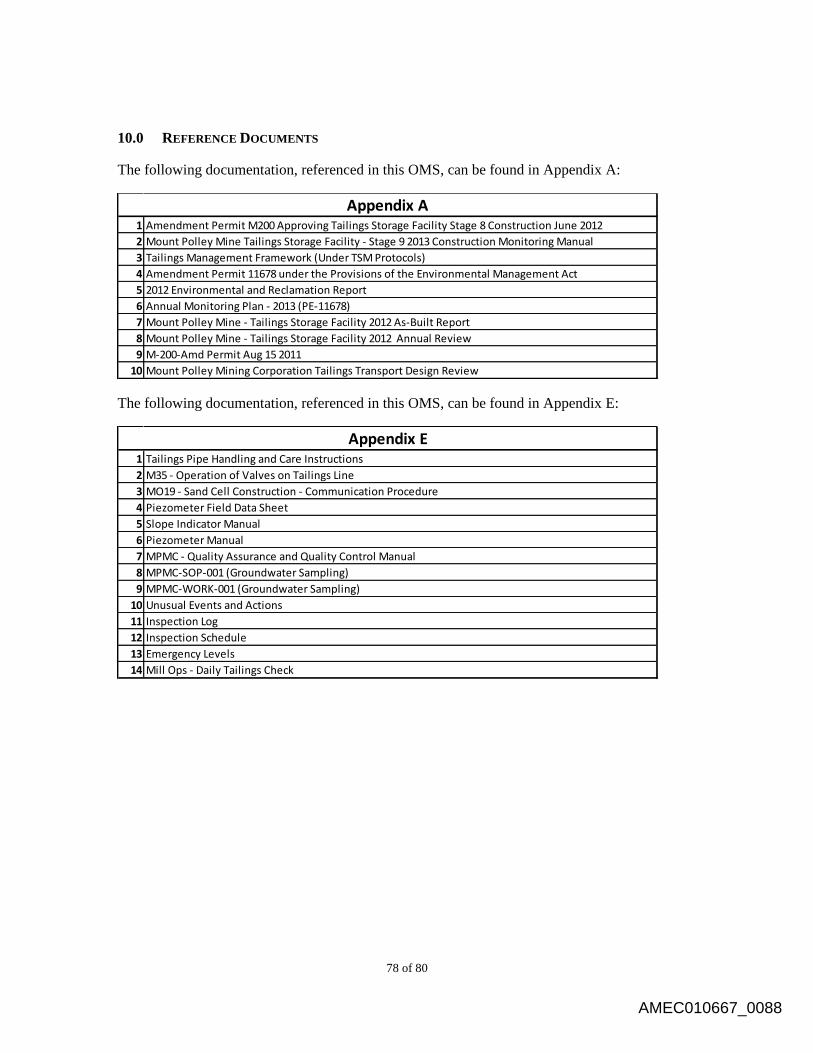
78 of 80
10.0 REFERENCE DOCUMENTS
The following documentation, referenced in this OMS, can be found in Appendix A:
1 Amendment Permit M200 Approving Tailings Storage Facility Stage 8 Construction June 2012
2 Mount Polley Mine Tailings Storage Facility - Stage 9 2013 Construction Monitoring Manual
3 Tailings Management Framework (Under TSM Protocols)
4 Amendment Permit 11678 under the Provisions of the Environmental Management Act
5 2012 Environmental and Reclamation Report
6 Annual Monitoring Plan - 2013 (PE-11678)
7 Mount Polley Mine - Tailings Storage Facility 2012 As-Built Report
8 Mount Polley Mine - Tailings Storage Facility 2012 Annual Review
9 M-200-Amd Permit Aug 15 2011
10 Mount Polley Mining Corporation Tailings Transport Design Review
Appendix A
The following documentation, referenced in this OMS, can be found in Appendix E:
1 Tailings Pipe Handling and Care Instructions
2 M35 - Operation of Valves on Tailings Line
3 MO19 - Sand Cell Construction - Communication Procedure
4 Piezometer Field Data Sheet
5 Slope Indicator Manual
6 Piezometer Manual
7 MPMC - Quality Assurance and Quality Control Manual
8 MPMC-SOP-001 (Groundwater Sampling)
9 MPMC-WORK-001 (Groundwater Sampling)
10 Unusual Events and Actions
11 Inspection Log
12 Inspection Schedule
13 Emergency Levels
14 Mill Ops - Daily Tailings Check
Appendix E
AMEC010667_0088
79 of 80
11.0 CERTIFICATION AND DISTRIBUTION
Control of this Manual 11.1
This manual will be controlled by the Tailings Project Manager. Copies will be
maintained at the following locations:
One (1) copy for Mount Polley Mining Corporation (Vancouver office),
One (1) copy for the Mine’s General Manager,
One (1) copy for the Mine Operation Manager’s office,
One (1) copy in the Tailings Project Manager’s office,
One (1) copy for the Mill Superintendent,
One (1) copy for the Mill Maintenance Superintendent,
One (1) copy for the Operating Crew (Mill Shifter’s Office),
One (1) copy for the Design Engineer of Record; and
One (1) copy for the MEM Geotechnical Manager.
The Tailings Project Manager is responsible for maintaining a record of the location
of each copy of the OMS Manual and to ensure the copies in these locations are kept
up to date.
Distribution of the Manual 11.2
A letter of transmittal that clearly identifies the distribution list must accompany each
revision of this manual. An update may comprise the entire manual or be limited to
specific pages or sections. A copy of each transmittal letter must be kept on record in
the office of the Tailings Project Manager. Each revised page of the manual must be
clearly marked as to the revision date prior to replacement. The replaced pages must
be filed and kept on record in the office of the Tailings Project Manager.
AMEC010667_0089

80 of 80
Certification of the Manual 11.3
This report was prepared and approved by the undersigned.
Prepared by:
Luke Moger
Project Engineer, Tailings Project Manager
Approved by:
Tim Fisch
General Manager
AMEC010667_0090