mott versa pro flail - cdnmedia.endeavorsuite.com · mott® versa pro flail rev 07/10 part no....
TRANSCRIPT

ALAMO INDUSTRIAL1502 E. WalnutSeguin, Texas 78155830-379-1480
OPERATOR'S MANUALwith PARTS LISTING
© 2003 Alamo Group Inc.
MOTT ®
VERSA PRO FLAIL Rev 07/10 Part No. 803350

TO THE OWNER/OPERATOR/DEALER
All implements with moving parts are potentially hazardous. There is no substitute for a cautious, safe-minded operatorwho recognizes the potential hazards and follows reasonable safety practices. The manufacturer has designed thisimplement to be used with all its safety equipment properly attached to minimize the chance of accidents.
BEFORE YOU START!! Read the safety messages on the implement and shown in your manual. Observethe rules of safety and common sense!
WARRANTY INFORMATION:
Read and understand the complete Warranty Statement found in this Manual. Fill out the Warranty Registration Formin full and return it to Alamo within 30 Days. Make certain the Serial Number of the Machine is recorded on the WarrantyCard and on the Warranty Form that you retain.

TABLE OF CONTENTS
SAFETY SECTION ................................................................................................................................. 1-1Safety Information ...................................................................................................................... 1-2Decal Location ........................................................................................................................... 1-4Federal Laws & Regulations .............................................................................................. 1-18
INTRODUCTION SECTION..................................................................................................................... 2-1Sepecifications ........................................................................................................................... 2-5
ASSEMBLY SECTION ............................................................................................................................ 3-1Tractor Preparation ..................................................................................................................... 3-2Mainframe to Attachment Frame Assembly ................................................................................ 3-3Tractor to Attachment Frame Assembly ..................................................................................... 3-4Driveline Attachment .................................................................................................................. 3-5Center & Wing Mower Assembly ................................................................................................ 3-5Wing Mower Attachment ............................................................................................................ 3-6Lift Frame to Mower ................................................................................................................... 3-6Electrical Connections & Schematic .......................................................................................... 3-7Center Mower Assembly ............................................................................................................ 3-9Hydraulic Connections ............................................................................................................... 3-12
OPERATION SECTION .......................................................................................................................... 4-1Start of Cut ................................................................................................................................. 4-2Off-On Switch ............................................................................................................................. 4-2Cut Off Switch ............................................................................................................................ 4-2Cuttershaft & Ground Speed ....................................................................................................... 4-2Hydraulic Oil Temperature .......................................................................................................... 4-2Troubleshooting .......................................................................................................................... 4-3
MAINTENANCE SECTION ...................................................................................................................... 5-1Daily Checks .............................................................................................................................. 5-2Lubrication ................................................................................................................................. 5-3Hydraulic System Filter .............................................................................................................. 5-4Replacing Belts .......................................................................................................................... 5-7Adjusting Cutting Height ............................................................................................................. 5-7Roller Bearing Replacement ....................................................................................................... 5-8Cuttershaft Bearing Replacement ............................................................................................... 5-9Cutter Knife Replacement ........................................................................................................... 5-11Hydraulics .................................................................................................................................. 5-12Hydraulic Pump Replacement .................................................................................................... 5-13Reservoir .................................................................................................................................... 5-14Solenoid Control Valve ............................................................................................................... 5-14Hydraulic Pump .......................................................................................................................... 5-15Hydraulic Motor .......................................................................................................................... 5-18Lift Cylinders ............................................................................................................................. 5-20Slip Clutch Replacement ............................................................................................................ 5-21Tank Filling Instructions .............................................................................................................. 5-23
PARTS SECTION ................................................................................................................................... 6-1Parts Ordering Guide .................................................................................................................. 6-2Parts Table of Contents .............................................................................................................. 6-3


Safety Section 1-1VERSA PRO 04/02
© 2002 Alamo Group Inc.
SAFETYSECTION

Safety Section 1-2VERSA PRO 3/93
SAFETY
© 2002 Alamo Group Inc.
SA
FE
TY
A safe and careful operator is the best operator. Safety is of primary importance to the manufac-turer and should be to the owner/operator. Most accidents can be avoided by being aware ofyour equipment, your surroundings, and observing certain precautions. The first section of thismanual includes a list of Safety Messages that, if followed, will help protect the operator andbystanders from injury or death. Read and understand these Safety Messages before assem-bling, operating or servicing this implement. This equipment should only be operated by thosepersons who have read the Manual, who are responsible and trained, and who know how to do
so safely and responsibly.
The Safety Alert Symbol combined with a Signal Word, as seen below, is used throughout thismanual and on decals which are attached to the equipment. The Safety Alert Symbol means:“ATTENTION! BECOME ALERT! YOUR SAFETY IS INVOLVED!” The Symbol and SignalWord are intended to warn the owner/operator of impending hazards and the degree of possibleinjury faced when operating this equipment..
CAUTION! The lowest level of Safety Message; warns of possible injury. Decals located on the Equipment with this Signal Word are Black and Yellow.
WARNING! Serious injury or possible death! Decals are Black and Orange.
DANGER! Imminent death/critical injury. Decals are Red and White. (SG-1)
Practice all usual and customary safe working precautions andabove all---remember safety is up to YOU. Only YOU can preventserious injury or death from unsafe practices.
READ, UNDERSTAND, and FOLLOW the following SafetyMessages. Serious injury or death may occur unless care istaken to follow the warnings and instructions stated in the SafetyMessages. Always use good common sense to avoid hazards.
(SG-2)

Safety Section 1-3VERSA PRO 3/93
SAFETY
© 2002 Alamo Group Inc.
SA
FE
TY
!Si no lee Ingles, pida ayuda a alguien quesi lo lea para que le traduzca las medidasde seguridad. (SG-3)
PELIGRO! LEA ELINSTRUCTIVO!
DANGER! Never operate the Tractor or Implement until you have read andcompletely understand this Manual, the Tractor Operator’s Manual,and each of the Safety Messages found in the Manual or on the Tractorand Implement. Learn how to stop the tractor engine suddenly in anemergency. Never allow inexperienced or untrained personnel toooperate the Tractor and Implement without supervision. Make surethe operator has fully read and understood the manuals prior tooperation. (SG-4)
WARNING! Always maintain the safety decals in good readable condition. If the decalsare missing, damaged, or unreadable, obtain and install replacementdecals immediately. (SG-5)
WARNING! Make certain that the “Slow Moving Vehicle” (SMV) sign is installed insuch a way as to be clearly visible and legible. When transporting theEquipment use the Tractor flashing warning lights and follow all local trafficregulations. (SG-6)
WARNING! Operate this Equipment only with a Tractor equipped with an approvedroll-over-protective system (ROPS). Always wear seat belts. Seriousinjury or even death could result from falling off the tractor--particularlyduring a turnover when the operator could be pinned under the ROPS.(SG-7)
WARNING! Do not modify or alter this Implement. Do not permit anyone to modifyor alter this Implement, any of its components or any Implementfunction. (SG-8)
DANGER! BEFORE leaving the tractor seat, always engage the brake and/or set thetractor transmission in parking gear, disengage the PTO, stop the engine,remove the key, and wait for all moving parts to stop. Place the tractor shiftlever into a low range or parking gear to prevent the tractor from rolling.Never dismount a Tractor that is moving or while the engine is running.Operate the Tractor controls from the tractor seat only.
(SG-9)
DANGER! Never allow children or other persons to ride on the Tractor or Implement.Falling off can result in serious injury or death.
(SG-10)

Safety Section 1-4VERSA PRO 3/93
SAFETY
© 2002 Alamo Group Inc.
SA
FE
TY
DANGER! Never allow children to operate or ride on the Tractor or Implement. (SG-11)
WARNING! Do not mount the Tractor while the tractor is moving. Mount theTractor only when the Tractor and all moving parts are completelystopped. (SG-12)
DANGER! Start tractor only when properly seated in the Tractor seat. Starting atractor in gear can result in injury or death. Read the Tractor operatorsmanual for proper starting instructions. (SG-13)
DANGER! Never work under the Implement, the framework, or any lifted componentunless the Implement is securely supported or blocked up to preventsudden or inadvertent falling which could cause serious injury or evendeath. (SG-14)
DANGER! Do not operate this Equipment with hydraulic oil leaking. Oil isexpensive and its presence could present a hazard. Do not check forleaks with your hand! Use a piece of heavy paper or cardboard. High-pressure oil streams from breaks in the line could penetrate the skinand cause tissue damage including gangrene. If oil does penetrate theskin, have the injury treated immediately by a physician knowledgeableand skilled in this procedure. (SG-15)
WARNING! The operator and all support personnel should wear hard hats, safetyshoes, safety glasses, and proper hearing protection at all times forprotection from injury including injury from items thrown by theequipment. (SG-16)

Safety Section 1-5VERSA PRO 3/93
SAFETY
© 2002 Alamo Group Inc.
SA
FE
TY
CAUTION! PROLONGED EXPOSURE TO LOUD NOISE MAY CAUSEPERMANENT HEARING LOSS! Tractors with or without anImplement attached can often be noisy enough to cause permanenthearing loss. We recommend that you always wear hearingprotection if the noise in the Operator’s position exceeds 80db.Noise over 85db over an extended period of time will cause severehearing loss. Noise over 90db adjacent to the Operator over anextended period of time will cause permanent or total hearing loss.Note: Hearing loss from loud noise [from tractors, chain saws,radios, and other such sources close to the ear] is cumulative over alifetime without hope of natural recovery. (SG-I7)
WARNING! Transport only at safe speeds. Serious accidents and injuries can resultfrom operating this equipment at unsafe speeds. Understand the Tractorand Implement and how it handles before transporting on streets andhighways. Make sure the Tractor steering and brakes are in good conditionand operate properly.
Before transporting the Tractor and Implement, determine the safetransport speeds for you and the equipment. Make sure you abide bythe following rules:
Be aware of the operating conditions. Do not operate the Tractor withweak or faulty brakes. When operating down a hill or on wet or rain slickroads, the braking distance increases: use extreme care and reduce yourspeed. When operating in traffic always use the Tractor’s flashing warninglights and reduce your speed. Be aware of traffic around you andwatchout for the other guy. (SG-19)
Test the equipment at a slow speed in turns. Increase the speedthrough the turn only after you determine that it is safe to operateat a higher speed. Use extreme care and reduce your speed whenturning sharply to prevent the tractor and implement from turningover. Determine the maximum safe turning speed for you and thisequipment before operating on roads or uneven ground.Only transport the Tractor and Implement at the speeds that youhave determined are safe and which allow you to properly control theequipment.
Test the tractor at a slow speed and increase the speed slowly.Apply the Brakes smoothly to determine the stoppingcharacteristics of the Tractor and Implement.As you increase the speed of the Tractor the stopping distanceincreases. Determine the maximum safe transport speed foryou and this Equipment.
2.
1.
3.
WARNING! Never attempt to lubricate, adjust, or remove material from the Implementwhile it is in motion or while tractor engine is running. Make sure thetractor engine is off before working on the Implement.
(SG-20)

Safety Section 1-6VERSA PRO 3/93
SAFETY
© 2002 Alamo Group Inc.
SA
FE
TY
WARNING! Transport only at safe speeds. Serious accidents and injuries can resultfrom operating this equipment at unsafe speeds. Understand the Tractorand Implement and how it handles before transporting on streets andhighways. Make sure the Tractor steering and brakes are in good conditionand operate properly.
Before transporting the Tractor and Implement, determine the safetransport speeds for you and the equipment. Make sure you abide bythe following rules:
Be aware of the operating conditions. Do not operate the Tractor withweak or faulty brakes. When operating down a hill or on wet or rain slickroads, the braking distance increases: use extreme care and reduce yourspeed. When operating in traffic besure to use the Tractor’s directionalindicator or flashher lights to properly indicate your movement. Alwaysuse the Tractor flashing lights when operating the Tractor and Implementon or near roads and streets. Be aware of traffic around you and watchout for the other guy. (SG-19)
Test the equipment at a slow speed in turns. Increase the speedthrough the turn only after you determine that it is safe to operateat a higher speed. Use extreme care and reduce your speed whenturning sharply to prevent the tractor and implement from turningover. Determine the maximum safe turning speed for you and thisequipment before operating on roads or uneven ground.Only transport the Tractor and Implement at the speeds that youhave determined are safe and which allow you to properly control theequipment.
Test the tractor at a slow speed and increase the speed slowly.Apply the Brakes smoothly to determine the stoppingcharacteristics of the Tractor and Implement.As you increase the speed of the Tractor the stopping distanceincreases. Determine the maximum safe transport speed foryou and this Equipment.
2.
1.
3.
WARNING! Periodically inspect all moving parts for wear and replace whennecessary with authorized service parts. Look for loose fasteners,worn or broken parts, and leaky or loose fittings. Make sure all pinshave cotter pins and washers. Serious injury may occur from notmaintaining this machine in good working order. (SG-21)
WARNING! Always read carefully and comply fully with the manufacturers instructionswhen handling oil, solvents, cleansers, and any other chemical agent.(SG-22)

Safety Section 1-7VERSA PRO 3/93
SAFETY
© 2002 Alamo Group Inc.
SA
FE
TY
DANGER! Never run the tractor engine in a closed building or without adequateventilation. The exhaust fumes can be hazardous to your health.
(SG-23)
DANGER! KEEP AWAY FROM ROTATING ELEMENTS to prevent entanglementand possible serious injury or death. (SG-24)
DANGER! Never allow children to play on or around Tractor or Implement. Childrencan slip or fall off the Equipment and be injured or killed. Children cancause the Implement to shift or fall crushing themselves or others. (SG-25)
WARNING! Do not exceed the rated PTO speed for the Implement. Excessive PTOspeeds can cause Implement driveline or blade failures resulting in seriousinjury or death. (SG-26)
DANGER! NEVER use drugs or alcohol immediately before or while operating theTractor and Implement. Drugs and alcohol will affect an operator’salertness and coordination and therefore affect the operator’s ability tooperate the equipment safely. Before operating the Tractor orImplement, an operator on prescription or over-the-counter medicationmust consult a medical professional regarding any side effects of themedication that would hinder their ability to operate the Equipmentsafely. NEVER knowingly allow anyone to operate this equipmentwhen their alertness or coordination is impaired. Serious injury ordeath to the operator or others could result if the operator is under theinfluence of drugs or alcohol. (SG-27)
DANGER! Operate the Tractor and/or Implement controls only while properly seated inthe Tractor seat with the seat belt securely fastened around you. Inadvertentmovement of the Tractor or Implement may cause serious injury or death. (SG-
29)
WARNING! Mow only in conditions where you have clear visibility in daylight or withadequate artificial lighting. Never mow in darkness or foggy conditionswhere you cannot clearly see at least 100 yards in front and to the sides ofthe tractor and mower. Make sure that you can clearly see and identifypassersby, steep slopes, ditches, drop-offs, overhead obstructions, powerlines, debris and foreign objects. If you are unable to clearly see this typeof items discontinue mowing. (SGM-1)
DANGER! The rotating parts of this machine have been designed and tested forrugged use. However, the blades could fail upon impact with heavy, solidobjects such as metal guard rails and concrete structures. Such impactcould cause the broken objects to be thrown outward at very highvelocities. To reduce the possibility of property damage, serious injury,or even death, never allow the cutting blades to contact such obstacles.(SGM-4)

Safety Section 1-8VERSA PRO 3/93
SAFETY
© 2002 Alamo Group Inc.
SA
FE
TY
WARNING! Extreme care should be taken when operating near loose objects suchas gravel, rocks, wire, and other debris. Inspect the area beforemowing. Foreign objects should be removed from the site to preventmachine damage and/or bodily injury or even death. Any objects thatcannot be removed must be clearly marked and carefully avoided bythe operator. Stop mowing immediately if blades strike a foreignobject. Repair all damage and make certain rotor or blade carrier isbalanced before resuming mowing. (SGM-5)
WARNING! Many varied objects, such as wire, cable, rope, or chains, can becomeentangled in the operating parts of the mower head. These items couldthen swing outside the housing at greater velocities than the blades. Sucha situation is extremely hazardous and could result in serious injury oreven death. Inspect the cutting area for such objects before mowing.Remove any like object from the site. Never allow the cutting blades tocontact such items. (SGM-6)
WARNING! Mow at the speed that you can safely operate and control the tractor andmower. Safe mowing speed depends on terrain condition and grass type,density, and height of cut. Normal ground speed range is from 0 to 5 mph.Use slow mowing speeds when operating on or near steep slopes,ditches, drop-offs, overhead obstructions, power lines, or when debris andforeign objects are to be avoided. (SGM-7)
WARNING! Avoid mowing in reverse direction when possible. Check to make surethere are no persons behind the mower and use extreme care whenmowing in reverse. Mow only at a slow ground speed where you can safelyoperate and control the tractor and mower. Never mow an area that youhave not inspected and removed debris or foreign material. (SGM-8)
DANGER! Replace bent or broken blade with new blades. NEVER ATTEMPT TOSTRAIGHTEN OR WELD ON BLADES SINCE THIS WILL LIKELYCRACK OR OTHERWISE DAMAGE THE BLADE WITHSUBSEQUENT FAILURE AND POSSIBLE SERIOUS INJURY FROMTHROWN BLADES. (SGM-10)
WARNING! Do not mow with two machines in the same area except with Cab tractorswith the windows closed. (SGM-11)
DANGER! Always disconnect the main PTO Driveline from the Tractor beforeperforming service on the Mower. Never work on the Mower with thetractor PTO driveline connected and running. Blades or Drivelines couldturn without warning and cause immediate entanglement, injury or death.(SRM-3)
WARNING! Do not let the Blades turn when the Mower Deck is raised for anyreason, including clearance or for turning. Raising the Mowerdeck exposes the Cutting Blades which creates a potentiallyserious hazard and could cause serious injury or even death fromobjects thrown from the Blades. (SRM-7)

Safety Section 1-9VERSA PRO 3/93
SAFETY
© 2002 Alamo Group Inc.
SA
FE
TY
DANGER! There are obvious and hidden potential hazards in the operation of thisMower. REMEMBER! This machine is often operated in grass andin heavy weeds. The Blades of this Mower can throw objects if shieldsare not properly installed and maintained. Serious injury or evendeath may occur unless care is taken to insure the safety of theoperator, bystanders, or passersby in the area. Do not operate thismachine with anyone in the immediate area. Stop mowing if anyoneis within 100 yards of mower. (SFL-1)
DANGER! Do not put hands or feet under mower decks. Blade Contact can resultin serious injury or even death. Stay away until all motion has stoppedand the decks are securely blocked up. (SFL-2)
WARNING! Each Rear Wheel must have a minimum of 1,000 pounds contact with thesurface to prevent lateral instability and possible tip-over which couldresult in serious bodily injury or even death. Widen the wheel tread andadd weights if needed. Refer to the mounting instructions or callCustomer Service if you need assistance with Couterweight Procedure.(SFL-3)
WARNING! Do not operate Mower if excessive vibration exists. Shut down PTOand the Tractor engine. Inspect the Mower to determine the sourceof the vibration. If Mower blades are missing or damaged replacethem immediately. Do not operate the mower until the blades havebeen replaced and the Mower operates smoothly. Operating theMower with excessive vibration can result in component failure andbroken objects to be thrown outward at very high velocities. To reducethe possibility of property damage, serious injury, or even death, neverallow the Mower to be operated with blades missing. (SFL-4)
DANGER! All Safety Shields, Guards and Safety devices including(but not limited to) - the Deflectors, Steel Guards,Gearbox Shields, PTO integral shields , and RetractableDoor Shields should be used and maintained in goodworking condition. All safety devices should be inspectedcarefully at least daily for missing or broken components.Missing, broken, or worn items must be replaced atonce to reduce the possibility of injury or death fromthrown objects, entanglement, or blade contact. (SFL-5)
WARNING! Never leave Tractor and Implement unattended while the implement is inthe lifted position. Accidental operation of lifting lever or a hydraulic failuremay cause sudden drop of unit with injury or death by crushing. Toproperly park the implement when disconnecting it from the tractor, lowerthe stand and put the retaining pin securely in place, or put a securesupport under the A-Frame. Lower the implement carefully to the ground.Do not put hands or feet under lifted components. (SPT-1)

Safety Section 1-10VERSA PRO 3/93
SAFETY
© 2002 Alamo Group Inc.
SA
FE
TY
DANGER! Flail Mowers are capable under adverse conditions ofthrowing objects for great distances (100 yards ormore) and causing serious injury or death. Followsafety messages carefully.
-Front and Rear Deflectors, Chain Guards, or Bands are installed and in good, workable condition; -Mower sections or Wings are running close to and parallel to the ground without exposed Blades; -Passersby are outside the existing thrown-object zone; -All areas have been thoroughly inspected and all foreign material such as rocks, cans, glass, and general debris has been removed.
NOTE: Where there are grass and weeds high enough to hide debristhat could be struck by the blades, the area should be: inspectedand large debris removed, mowed at an intermediate height, inspected,closely with any remaining debris being removed, and mowed againat desired final height. (This will also reduce power requiredto mow,reduce wear and tear on the Mower drivetrain, spread cut materialbetter, eliminate streaking, and make the final cut more uniform.)
(SFL-6)
STOP MOWING IF PASSERSBYARE WITHIN 100 YARDS UNLESS:
WARNING! Be particularly careful when transporting the Implement with the Tractor.Turn curves or go up hills only at a low speed and using a gradualsteering angle. Rear mounted implements move the center of gravity tothe rear and remove weight from the front wheels. Make certain, byadding front ballast, that at least 20% of the tractor’s weight is on thefront wheels to prevent rearing up, loss of steering control or Tractor tip-over. Slow down on rough or uneven surfaces to prevent loss ofsteering control which could result in property damage or possible injury.Do not transport unless 3-Point lift lever is fully raised and in the latchedtransport position. Dropping implement in transport can cause seriousdamage to the tractor and/or Implement and possibly cause the operatoror others to be injured or killed. (S3PT-2)
WARNING! Use extreme care when lowering or unfolding the implement’s wings.Make sure no bystanders are close by or underneath the wings. Allowample clearance around the implement when folding or unfolding thewings. Use extreme caution around buildings or overhead power lines.
(S3PT-5)
DANGER! Make sure the PTO shield, integral driveline shields, and input shields areis installed when using PTO-driven equipment. Always replace anyshield if it is damaged or missing. (S3PT-8)
WARNING! Relieve hydraulic pressure prior to doing any maintenance or repair workon the Implement. Place the Implement on the ground or securelyblocked up, disengage the PTO, and turn off the tractor engine. Pushand pull the Remote Cylinder lever in and out several times prior tostarting any maintenance or repair work. (S3PT-9)
Safety Section 1-11VERSA PRO 3/93
SAFETY
© 2002 Alamo Group Inc.
SA
FE
TY
WARNING! The rotating parts of this machine continue to rotate even after the PTOhas been turned off. The operator should remain in his seat for 60seconds after the brake has been set, the PTO disengaged, the tractorturned off, and all evidence of rotation has ceased. (3PT-10)
“Wait a minute...Save a life!”
DANGER! This Implement is wider than the Tractor. Be careful when operatingor transporting this equipment to prevent the Implement from runninginto or striking sign posts, guard rails, concrete abutments or othersolid objects. Such an impact could cause the Implement and Tractorto pivot violently resulting in loss of steering control, serious injury, oreven death. Never allow the Implement to contact obstacles. (S3PT-12)
DANGER! When the Wings are folded for transport, the center of gravity is raisedand the possibility of overturn is increased. Drive slowly and useextremecaution when turning on hillsides. Overturning the Implementcould cause the Implement to overturn the Tractor and vice versa resultingin serious injury or even death. Never fold wings on a hillside...theImplement may overturn. (STI-2)
DANGER! DO NOT allow any person under a folded wing unless wing is securelylocked up or supported. DO NOT approach the Implement unless theTractor is turned off and all motion has ceased. Never work under theframe work, or any lifted component unless the implement is securelysupported or blocked up. A sudden or inadvertent fall by any of thesecomponents could cause serious injury or even death. (STI-3)
PARTS INFORMATION
Alamo Industrial mowers use balanced and matched system components for blade carriers, blades,cuttershafts, knives, knife hangers, rollers, drivetrain components, and bearings. These parts are made andtested to Alamo Industrial specifications. Non-genuine "will fit" parts do not consistently meet thesespecifications. The use of “will fit” parts may reduce mower performance, void mower warranties, and presenta safety hazard. Use genuine Alamo Industrial mower parts for economy and safety. (SPAM-1)
SEE YOUR ALAMO DEALER
In addition to the design and configuration of this Implement, including Safety Signs and Safety Equipment, hazardcontrol and accident prevention are dependent upon the awareness, concern, prudence, and proper training ofpersonnel involved in the operation, transport, maintenance, and storage of the machine. Refer also to SafetyMessages and operation instruction in each of the appropriate sections of the Tractor and Equipment Manuals.Pay close attention to the Safety Signs affixed to the Tractor and Equipment. (SG-18)

Safety Section 1-12VERSA PRO 10/01
SAFETY
© 2002 Alamo Group Inc.
13
36
40
3941
37

Safety Section 1-13VERSA PRO 10/01
SAFETY
© 2002 Alamo Group Inc.
ITEM PART NO. QTY LEVEL DESCRIPTION
1 002369 4 DANGER Multiple-Hazard2 00753840 2 DANGER Folding Wing/Wings Raised3. 00756004 2 DANGER D/L Shield Missing4 00756005 2 DANGER Rotating D/L, Entanglement5 00756007 3 WARNING Use/Repair Shields/Guards6 00756059 3 DANGER Oil Penetration, Leaks7 02967668 3 DANGER Cutting Blades, Thrown Objects8 00746494 1 DANGER Driveline Hazards9 00758194 3 WARNING Belt/Pulley Pinch Point10 02962765 2 DANGER Crushing From Folding Hazard11 002425 3 DANGER Removing Front Shield12 02971123 1 WARNING Pressurized Tank13 03200347 * REFLCTR SMV Reflector14 1458392 2 REFLCTR Red Reflector Decal15 1458393 4 REFLCTR Yellow Reflector Decal16 02966305 1 INSTRUCT Hyd Oil and Type17 02925100 3 INSTRUCT Genuine ALAMO Flail Parts18 002023 3 INSTRUCT Cutting Height Adjustment19 000108 3 INSTRUCT Flail Operation20 000678 2 INSTRUCT Grease Fitting Inside21 002490 3 INSTRUCT Wing Unit Lube Chart22 02962748 2 INSTRUCT On/Off Solenoid Switch23 02965093 1 INSTRUCT Do Not Overspeed Engine23A 00763977 1 INSTRUCT Notice to Owner24 001650 1 LOGO ALAMO (7.5 x 7)25 001651 4 LOGO ALAMO IND26 02960766 3 LOGO ALAMO (4 x 5)28 002489 3 NAME VERSA PRO (Name)29 nfs (L) 1 SER PLT Left Wing Serial Plate30 nfs (R) 1 SER PLT Right Wing Serial Plate31 nfs (C) 1 SER PLT Center Mower Serial Plate32 nfs (F) 1 SER PLT VERSA PRO Serial Plate33 002505 1 INSTRUCT Wing Lowering34 001830 1 INSTRUCT Lubrication Rear35 00773723 2 DANGER Peligro, Driveline36 02977417 1 INSTRUCT Operators Manual Inside37 02977385 1 --------------- Canister, Operators Manual38 803350C 1 --------------- Operators Manual39 10058000 4 --------------- Bolt40 00017000 4 --------------- Lockwasher41 00024100 4 --------------- Flatwasher

Safety Section 1-14VERSA PRO 3/93
SAFETY
© 2002 Alamo Group Inc.
SA
FE
TY
(2) - 00753840
(3) - 00756004
(6) - 00756059 (4) - 00756005
(9) - 00758194(22) - 02962748
(5) - 00756007

Safety Section 1-15VERSA PRO 3/93
SAFETY
© 2002 Alamo Group Inc.
SA
FE
TY
(7) - 00746485
(11) - 002425
(12) - 02971123
(8) - 00746494
(16) - 02966307
(20) - 000678
(13) - 03200347
(10) - 02962765
R 9-25-00

Safety Section 1-16VERSA PRO 3/93
SAFETY
© 2002 Alamo Group Inc.
SA
FE
TY
(23A) - 00763977
(17) - 03200432
(19) - 000108
(18) - 002023
(23) - 02965093
(1) 002369 Front Cover(14) 99203 Red Reflector Decal(15) 99204 Yellow Reflector Decal(24) 001650 ALAMO (7.5 x 7)(25) 001651 ALAMO (Built by Mott)(26) 02960766 ALAMO (4 x 5)(27) 002491 Name Decal (MOTT)(28) 002489 Name Decal (VERSA PRO)
R 04-21-99
(34) - 02977417
(29) nfs (L) SERIAL PLATE(30) nfs (R) SERIAL PLATE(31) nfs (C) SERIAL PLATE(32) nfs (F) SERIAL PLATE

Safety Section 1-17VERSA PRO 10/01
SAFETY
© 2002 Alamo Group Inc.
(33) - 002505
(21) - 002490
* LUBRICATE ALL POINTS EVERY 8 HOURS OF OPERATION
LUBRICATION CHART
WING LOWERING INSTRUCTIONS
1. Be sure forward/reverse lever is locked in neutral positionbefore attempting to lower wings from locked position.
2. It is necessary to fully raise wings before releasing latches.
3. Pull red knobs. Slowly lower wings by pushing control leversforward.
4. Wings will automatically lock when raised to vertical position.
P/N 002505

Safety Section 1-18VERSA PRO 3/93
SAFETY
© 2002 Alamo Group Inc.
SA
FE
TY
This section is intended to explain in broad terms the concept and effect of federal laws and regulations concerningemployer and employee equipment operators. This section is not intended as a legal interpretation of the law andshould not be considered as such.
Employer-Employee Operator RegulationsU.S. Public Law 91-596 (The Williams-Steiger Occupational and Health Act of 1970) OSHA
This Act Seeks:“...to assure so far as possible every working man and woman in the nation safe and healthful working conditionsand to preserve our human resources...”
DUTIESSec. 5 (a) Each employer-(1) shall furnish to each of his employees employment and a place of employment which are free from recognizedhazards that are causing or are likely to cause death or serious physical harm to his employees;(2) shall comply with occupational safety and health standards promulgated under this Act.(b) Each employee shall comply with occupational safety and health standards and all rules, regulations andorders issued pursuant to this Act which are applicable to his own actions and conduct.
OSHA RegulationsOSHA regulations state in part: “At the time of initial assignment and at least annually thereafter, the employershall instruct every employee in the safe operation and servicing of all equipment with which the employee is, or willbe involved.”
Employer Responsibilities:To ensure employee safety during Tractor and Implement operation, it is the employer’s responsibility to:
1. Train the employee in the proper and safe operation of the Tractor and Implement.
2. Require that the employee read and fully understand the Tractor and Implement Operator’s manual.
3. Permit only qualified and properly trained employees to operate the Tractor and Implement.
4. Maintain the Tractor and Implement in a safe operational condition and maintain all shields and guards on theequipment.
5. Ensure the Tractor is equipped with a functional ROPS and seat belt and require that the employee operatorsecurely fasten the safety belt and operate with the ROPS in the raised position at all times.
6. Forbid the employee operator to carry additional riders on the Tractor or Implement.
7. Provide the required tools to maintain the Tractor and Implement in a good safe working condition and providethe necessary support devices to secure the equipment safely while performing repairs and service.
8. Require that the employee operator stop mowing if bystanders or passerbys come within 100 yards.
Child Labor Under 16 Years of AgeSome regulations specify that no one under the age of 16 may operate power machinery. It is your responsibilityto know what these regulations are in your own area or situation. (Refer to U.S. Dept. of Labor, EmploymentStandard Administration, Wage & Home Division, Child Labor Bulletin #102.)
FEDERAL LAWS AND REGULATIONS

Introduction Section 2-1VERSA PRO 04/02
© 2003 Alamo Group Inc.
INTRODUCTIONSECTION

Introduction Section 2-2VERSA PRO 3/93
INTRODUCTION
© 2003 Alamo Group Inc.
INTR
OD
UC
TIO
N
This Mower is designed with care and built with quality materials by skilled workers. Proper assembly,
maintenance, and operating practices, as described in this manual, will help the owner/operator get years of
satisfactory service from the machine.
The purpose of this manual is to familiarize, and instruct. The Assembly Section instructs the owner/operator
in the correct assembly of the Mower using standard and optional equipment. The Parts Listing section is
designed to familiarize the owner/operator with replaceable parts on the Mower. This section provides
exploded assembly drawings of each mower component illustrating each piece and the corresponding part
number.
Careful use and timely service saves extensive repairs and costly downtime losses. The Operation and
Maintenance Sections of the manual train the owner/operator how to work the Mower correctly and attend to
appropriate maintenance. The Trouble Shooting Guide helps diagnose difficulties with mower and offers
solution to the problems.
Safety is of primary importance to the owner/operator and to the manufacturer. The first section of this
manual includes a list of Safety Messages, that, if followed, will help protect the operator and bystanders
from injury or death. Many of the Safety Messages will be repeated throughout the manual. The owner/
operator/dealer should know these Safety Messages before assembly and be aware of the hazards of
operating this mower during assembly, use, and maintenance. The Safety Alert Symbol combined with a
Signal Word, as seen below, is intended to warn the owner/operator of impending hazards and the degree of
possible injury faced when operating this machine.
The lowest level of Safety Message; warns of possible minor injury. Decals locatedon the Mower with this Signal Word are Black and Yellow.
Serious injury or possible death! Decals are Black and Orange.
Imminent death/critical injury. Decals are Red and White.
CAUTION
WARNING
DANGER

Introduction Section 2-3VERSA PRO 3/93
INTRODUCTION
© 2003 Alamo Group Inc.
INTR
OD
UC
TION
Your Mower is designed for medium-duty cutting such as lawn maintenance plus small weed and grass control.With a reasonable amount of preventive maintenance, your Mower will provide years of dependable service.
DANGER NEVER ALLOW CHILDREN TO OPERATE, RIDE ON, OR COME CLOSE TOMOWER OR TRACTOR. Usually, 16-17 year-old teenagers who are mature andresponsible can operate the mower with reasonable safety if they have readOperator's Manual, been trained in safe operation of the machine, and arephysically large and strong enough to reach and operate controls easily.
For Non-Agricultural use, OSHA, ASAE, SAE, and ANSI standards require theuse of Chain Guards, Deflectors, or Solid Skirts at all times. The Mowermanufacturer strongly recommends the use of Chain Guards or Solid Skirts forAgricultural purposes as well, to reduce the risk of property damage, seriousbodily injury, or even death from objects thrown out by or from contact with theCutting Blades.
At least 20% of the tractor’s weight must be on the rear tires with the Mower liftedto provide adequate traction for safe steering under good conditions. Slowdown on hills, rough terrain, and curves.
DANGER
Front and rear and left and right are determined by the normal direction of travel the same as driving an automobile.
WARNING

Introduction Section 2-4VERSA PRO 04/03
INTRODUCTION
© 2003 Alamo Group Inc.
INTR
OD
UC
TIO
N
ATTENTION OWNER/OPERATOR
BEFORE OPERATING THIS MACHINE:
1. Carefully read the Operator’s Manual, completely understand the Safety Messages and
instructions, and know how to operate correctly both the tractor and Mower.
2. Fill out the Warranty Card in full. Be sure to answer all questions, including the Serial Number
of the Mower. Mail within 30 days of delivery date of this implement.
NOTE: Warranties are honored only if completed “Owner Registration and Warranty” forms are
received by AlLAMO within thirty days of delivery of the mower.
3. Record the Mower Model and Serial Numbers on the Warranty page at the back of the
Operator’s Manual. Keep this as part of the permanent maintenance file for the Mower.

Introduction Section 2-5VERSA PRO 3/93
INTRODUCTION
© 2003 Alamo Group Inc.
INTR
OD
UC
TION
SPECIFICATIONS
Hydraulic Oil Capacity: Total System Fill Capacity 25 Gallons.
Hydraulic Oil: Universal Tractor Hydraulic Oil
Grease: # 2 Lithium Base Bearing Grease and EP90 Gear Oil
SPECIFICATION OF THE POWER CIRCUIT:
Hydraulic Pump Speed: 2160 RPM @ 540 PTO Speed
Hydraulic Pump Rotation: Counter Clockwise (viewed from shaft end)
Hydraulic Motor Speed: 2000-2400 RPM
Maximum Rated Pressure: 4000 PSI
Rated Flow: 25 GPM at each of the Motors
Cuttershaft Speed: 2000-2400 RPM
Oil Operating Temperature: 180 deg.F max.
Hydraulic Pump: Tandem Piston type fixed displacement:2.77 cu. in./revolution, each section
Max. rated Pressure - 4000 PSIMaximum rated Flow: 36 GPM, each sectionMaximum rated Hydraulic Horsepower - 84HP each section
Hydraulic Motor: Piston type fixed Displacement: 2.48 cu.in./revolutionMaximum rated Speed: 3000 RPMMaximum operating Pressure: 4000 PSIMaximum rated Flow: 54 G.P.M.Relief Valve Setting: 4000 PSI
Motor Control Valve: Normally Open: 12 Volts DC Solenoid Cartridge TypeRated Pressure: 3750 PSIRated Flow: 36 GPM
Electric: Voltage at Solenoid: 12 Volts DCFuse rating: 6 AMPS, 32 VoltsSwitch rating: 15 AMPS, 125 VAC
Pressure Relief Valve: Direct acting Differential Piston TypeRelief Pressure Setting: 4000 PSIRated Flow: 40 GPM
Filtration: Full Flow, 10 Micron Nominal, Return Line Filter
Parameters of Control Circuit: Utilizes Tractor Remotes
Hydraulic Lift Cylinder: All Single ActingWings - 3-1/2 in. Bore x 6-3/16 in. StrokeCenter - 2 in. Bore x 9-1/4 in. Stroke
Cutting Height of Mowers: 1/2" to 6" (1/2" increments)


Assembly Section 3-1VERSA PRO 04/02
© 2003 Alamo Group Inc.
ASSEMBLYSECTION

Assembly Section 3-2
ASSEMBLY
VERSA PRO 3/93
© 2003 Alamo Group Inc.
AS
SE
MB
LY
IMPORTANT The hydraulic system must be kept "SURGICALLY CLEAN" to ensure proper operation andlong life of the pumps, motors, and valves. All components have protective caps overopenings connected to internal spaces to prevent contamination. It is important that care betaken during unpacking, assembly, and other contaminants which will damage parts.
DO NOT start the tractor unless the hydraulic system is filled with hydraulic oil. Running withoutoil will damage the pumps.
Check the oil level in the reservoir before start-up.
Care should be taken when filling the reservoir to prevent contamination of the hydraulic system.Always use new hydraulic fluid when filling the system. USE ONLY UNIVERSAL TRACTORHYDRAULIC OIL IN THE HYDRAULIC SYSTEM.
Reference to the left or right side is determined while standing in the rear & facing in the direction of travel.
TRACTOR PREPARATION (Figure 1)
1. Remove the Anti-Sway Bars from tractor and Lower Links.
2. Remove the Pins that attach the Lower Links to the Down Links and the Tractor Lugs. Remove the Lower Links.Insert the Pins back into the Down Links and the Tractor Lugs. These Pins will be used when attaching the V-Pro to the tractor.
3. Remove the complete Draw Bar and carrier from the Tractor.
FIGURE 1
R 9-25-00

Assembly Section 3-3
ASSEMBLY
VERSA PRO 3/93
© 2003 Alamo Group Inc.
AS
SE
MB
LY
MAINFRAME TO ATTACHMENT FRAME ASSEMBLY (Figure 2)
Place Mainframe on a level surface. Raise Mainframe with a forklift or hoist and attach the Jackstands. RaiseJackstands until the Mainframe is raised to approximately 18". Align the Attachment Frame (3) lugs withMainframe, install the Pins (4) and retain with 1/2 x 1-3/4 bolts (5), flatwashers (6) and locknuts (7). Install the AxleMount Bars (8) and retain with Pins (9) and Cotter Pins (10).
NOTE: It will be necessary to lower tank assembly in order to install pin (4).
FIGURE 2
R 6-1-93

Assembly Section 3-4
ASSEMBLY
VERSA PRO 3/93
© 2003 Alamo Group Inc.
AS
SE
MB
LY
TRACTOR TO ATTACHMENT FRAME ASSEMBLY
Raise the Attachment Frame Arms(1) to a level height. Drive Tractor into Attachment Frame and align with theTractor Attachment Frame Mounts (2). Retain with bolt (3) and locknut (4). Figure 3. Attach the Axle Mount Bars(5) to the Tractor lugs with Pins (6) and Lynch Pins (7). Figure 4. Attach the Down Links (8) to the Mainframewith Pins (9) and Lynch Pins (10). Figure 5. NOTE: Adjust down links to 28" pin center.
FIGURE 3 FIGURE 4
FIGURE 5
9, 10
9, 10
8

Assembly Section 3-5
ASSEMBLY
VERSA PRO 3/93
© 2003 Alamo Group Inc.
AS
SE
MB
LY
DRIVELINE ATTACHMENT
Pull slide collar back and attach one end to the Tractor PTO. Move yoke back and forth until locking collar"clicks" forward and locks the yoke in place. Do the same to the other end of the Driveline on the SpeedIncreaser shaft.
FIGURE 6
CENTER & WING MOWER ASSEMBLY
Tip cutterhousing back and place a block under roller to safely support unit. Remove shipping skids and drivepulley side belt guard fender. If necessary, install knives, as shown, one row at a time. See rotation below.FOR FORWARD ROTATION: On the right wing and center unit, all knife pins must be installed with their headsfacing away from the cuttershaft pulley. On the left wing, the heads of the knife pins must face the cuttershaftpulley.FOR REVERSE ROTATION: On the right wing and center unit, all knife pins must be installed with their headsfacing toward the cuttershaft pulley. On the left wing, the heads of the knife pins must face away from thecuttershaft pulley.This will locate cotter pins where knives cannot reach them when flexing backward. The housing side sheet hasa hole in it which allows knife pins to be inserted into end lugs from outside the cutterhousing. After the cotter pinis installed, bend extended prong at a 45 Degree angle with prong parallel to lug.
With the cutterhousing tipped up, attach housing shoes/wear plate. Carriage bolt attaches to front mounting hole;plow bolts attach to middle and rear holes.
Plow Bolts
Carriage Bolt
Wear Plate
FIGURE 8FIGURE 7

Assembly Section 3-6
ASSEMBLY
VERSA PRO 3/93
© 2003 Alamo Group Inc.
AS
SE
MB
LY
WING MOWER ATTACHMENT
To attach wing mower to mainframe. Align tilt link (1) with actuator (2) and retain with pin (3). Proceed to lift frame(4) and align with lug on mainframe (5), retain with pin (6) and with pin (7). Secure all pins with 1/2" x 1 1/2" boltand 1/2" nut. Figure 9. Pin (3) will be secured with bolt that also secures pin for cylinder.
LIFT FRAME TO MOWER
Align toplink (1) to mower lugs (8), retain with pin (9) and lock with cotter pins (10). Align lift frame (4) with lugs atbottom of mower, retain with pivot pin (11) and lock with nut (12). Figure 9.Note: Use a thread locking material to secure nut (12) to pivot pin.
FIGURE 9

Assembly Section 3-7
ASSEMBLY
VERSA PRO 3/93
© 2003 Alamo Group Inc.
AS
SE
MB
LY
ELECTRICAL CONNECTION AT MOWER.
Connect terminals on harness to corresponding terminals on safety switch. Continue harness routing with hosesand attach connector at end of harness to solenoid coil on motor. Secure with screw and gasket provided withharness. Fig. 12. Refer to electrical schematic (Figure 13) for additional help.
FIGURE 12
ELECTRICAL CONNECTION AT TRACTOR
Battery cable must be disconnected to prevent any eletrical shock. Unscrew bottom screws from panel withregular tip screwdriver (Figure 10, item 1). Pull down on panel from bottom, and top should pop out. Placea small block of wood inside of console against side wall to protect wiring when drilling holes for switch.Both sides of console should be drilled for switch to be mounted (Figure 10, item 2). Once the switches areinstalled, connect switch connectors from harness to the top spade terminals of switch. Connect powerwires to ignition switch at accessory terminal (Figure 11, item 3). Connect ground wire to ground (Figure 11,item 4). Wire harness should then be routed through console, then through hole underneath seat at pivotpoint. Wire harness should then exit at hydraulic hoses connection, at front of tractor. Connect wire harnessfrom tractor to the wire harness from mower. Refer to electrical schematic (Figure 13) for additional help.
FIGURE 11FIGURE 10
1
2
4
3
R 2-16-94

Assembly Section 3-8
ASSEMBLY
VERSA PRO 3/93
© 2003 Alamo Group Inc.
AS
SE
MB
LY
FIGURE 14
CENTER MOWER ASSEMBLY
Attach the right and left Overarms (1) to the cutterhousing.Secure with 5/8 x 1-3/4 bolts (2) and locknuts (3). Attach theA-Frame Weldment (4) to the Overarms with bolts (2) andlocknuts (3). Figure 14.
FIGURE 13
ELECTRICAL SCHEMATIC
R 5-14-02

Assembly Section 3-9
ASSEMBLY
VERSA PRO 3/93
© 2003 Alamo Group Inc.
AS
SE
MB
LY
FIGURE 15 FIGURE 16
CENTER MOWER ASSEMBLY
1. Attach outboard bearing plate to cutterhousing.
FORWARD ROTATION (Bearing plate mounts on left side of cutterhousing.)
a. Secure with 3/8 NC x 7/8 Bolt and nut at front mounting hole. Torque to 35 ft-lbs. (Typ.)b. Secure with 3/8 NC x 2-1/4 Bolt, nut, lockwasher, and second nut at rear mounting hole. The Bolt is used asan anchor for the idler arm spring.
REVERSE ROTATION (Bearing plate mounts on right side of cutterhousing)
a. Secure with 3/8 NC x 2-1/4 Bolt, nut and second nut at front mounting hole. The Bolt is used as an anchor forthe idler arm spring.
b. Secure with 3/8 NC x 7/8 Bolt and nut at rear mounting hole.
2. Install gearbox & extension shaft assembly and PTO shield mounting bracketa. Remove existing nuts and lockwasher from bearing housing.
NOTE: On forward rotation units, remove only the lower two fasteners.
b. Slide bearing housing Bolt into proper holes in outboard bearing plate.
c. Attach gearbox and mounting bracket to gearbox mounting frame. Secure with 5/8 NC x 1-1/4 Bolt (uppergearbox feet), and 5/8 NC x 1-1/2 Bolt (lower gearbox feet)and Lockwashers. Torque to 170 ft-lbs. (Typ.)
d. Secure bearing housing to bearing plate with previously removed fasteners.
Shims
IMPORTANT: If extension shaft does not line-up with Gearbox, it may be necessary to shim gearbox mounting
lugs. To accomplish this, insert one gearbox retaining bolt (Figure 15) thru the mount plate and into the gearbox
housing. Do not tighten this bolt (it should have at least 1/4" free threads to move in and out). Assemble the
gearbox, shaft, shaft extension tube and the bearing to the bearing retainer plate mounted on the side sheet.
Tighten all fasteners except the one bolt in the gearbox mounting plate. Check the distance between the gearbox
mounting lugs and the mount plate. If required, insert shims from shim kit (P/N 000552) between gearbox
mounting lugs and mounting plate to insure the gearbox pulls up evenly on the mounting plate.
R 5-14-02

Assembly Section 3-10
ASSEMBLY
VERSA PRO 3/93
© 2003 Alamo Group Inc.
AS
SE
MB
LY
1
3
2
4
IDLER ARM ASSEMBLY
CENTER MOWER ASSEMBLY
Install idler arm assembly to bearing plate. Do not secure atthis time. Figure 17.
1. Remove fasteners and shaft protector from end of driveshaft. Lightly grease shaft. Install key and drive shaft pulley.Do not secure at this time. Figure 17.
2. Align all three pulleys. Use spacers and shims providedto achieve alignment, then secure idler arm assembly withcotter pin. Secure drive shaft pulley with fasteners removedin Step 1, above.
3. Install drive belt. Figure 18.
4. Attach spring. One end is inserted in idler arm spring armhole; the other end is attached to the long outboard bearingplate bolt.
FIGURE 18
FIGURE 17

Assembly Section 3-11
ASSEMBLY
VERSA PRO 3/93
© 2003 Alamo Group Inc.
AS
SE
MB
LY
INSTALLATION OF CENTER MOWER - (Figure 19)
1. To properly attach center mower to mainframe, align lower links (1) to overarms (2) and anti-sway bar (3).Attach with 7/8" x 5" bolt and 7/8" locknut (4).
2. Align toplink (5) with top of A-frame (6) on center mower and retain with pin (7), washers (8), and cotter pins.Attach the other end of the the toplink to the mainframe. Install 1" x 4" bolt through safety chain and retain with 1"locknut.
3. Continue with driveline by aligning slipclutch and gearbox shaft and slide slipclutch in and tighten bolt. On theother end of driveline pull slide collar back, slip into speed increaser shaft and release slide collar. Move drivelinein and out to insure driveline is secure.
4. Level front unit by adjusting top link. Be sure skid shoes are level with ground.
NOTE: Front Caster Wheels should be set about 2-4 inches above ground when mower is level.
FIGURE 19
R 2-4-93

Assembly Section 3-12
ASSEMBLY
VERSA PRO 3/93
© 2003 Alamo Group Inc.
AS
SE
MB
LY
HYDRAULIC CONNECTIONS
WARNING! Refer to the Tractor Manual when connecting hydraulic hoses to the tractor hydraulic system.Numerous precautions should be taken due to the possibility of a pressure buildup within thehydraulic circuit. Relieve the pressure before opening or entering the circuit. FLUID ESCAPINGUNDER PRESSURE CAN PENETRATE THE SKIN CAUSING SERIOUS INJURY. Ensure thathose fittings are secure before pressurizing the hydraulic systems.
IMPORTANT Once drivelines are installed, DO NOT start the tractor (which will turn the pumps) unless bothpower circuits are filled with the specified hydraulic fluid. Running pumps without oil will cause non-warrantable damage.
It is important that pipe thread sealant be used only on solid connections of pipe thread; never on connectionsbetween swivel fittings and solid male pipe threads or on straight thread "O" ring fittings. Use the pipe thread sealantsupplied. Do not substitute with some other type of sealant, i.e., teflon tape, paint, shellac, etc.
Hoses supplied have two types of fittings; solid or swivel. Some hoses have solid fittings on both ends; others havea solid fitting and a swivel fitting. Hoses with two solid fittings will fit into either a outer solid thread, or a swivel adapterunion. When installing either type hose, solid fittings must be installed first, then install the swivel end of the hose.
The VERSA PRO hydraulic system incorporates three basic types of hydraulic fittings:
a. Standard pipe (NPT or NPTF) thread fittings. This type requires a small amount of evenly-applied sealant.
b. Swivel fittings. This type does not require any sealant on the swivel end because it seals against an internalflare.
c. "O" Ring fittings. This type does not require any sealant on the "O" Ring end of the fitting.
It is extremely important to avoid getting pipe thread sealant inside the fittings or hoses. KEEP THE INTERIOROF ALL HYDRAULIC COMPONENTS SURGICALLY CLEAN. Inspect the inside diameter of each hose beforeassembly. Ensure that no obstruction is present. Dirt, sand, dust, etc., are abrasive and once in the system cancause immediate or early failure.
NOTE: Do not strap hoses together until all hoses and wiring are connected. Hoses and wiring should be routedso they do not lay on moving parts, too close to sharp edges, or near excessive heat.
R 06-30-94

Assembly Section 3-13
ASSEMBLY
VERSA PRO 3/93
© 2003 Alamo Group Inc.
AS
SE
MB
LY
HOSE CONNECTION AT TRACTOR
1. To properly connect hydraulic hoses to tractor, connect right wing hose P/N 02839000 (1), and left wing hoseP/N 02839000 (2).Figure 20.2. Connect center lift hose P/N 02964451 (3) to connection at center of tractor. Figure 20. This should be theremote valve with "Float" position. Always operate front mower in float detent position.
1 Right Wing
3 Center Lift
2 Left Wing
FIGURE 20
R 06-30-94

Assembly Section 3-14
ASSEMBLY
VERSA PRO 3/93
© 2003 Alamo Group Inc.
AS
SE
MB
LY
HYDRAULIC CONNECTIONS TO CYLINDERS
Connect the Hoses P/N 02965364 and P/N 02961321 from Tee to Center Lift Hydraulic Cylinders at rod end.
HYDRAULIC CONNECTIONS TO FILTER
Connect return hose P/N 002479 from right wing mower to elbow at filter (identified as "A"). Left wing mower willuse hose P/N 002477 and will be connected to Tee (identified as "B"). Figure 21.
"B" FROM LEFT WINGMOWER
"A" FROM RIGHTWING MOWER
HYDRAULIC CONNECTIONS TO PUMP
Connect right wing hydraulic motor to pump using hose P/N 002480 (identified by "C"). Left wing motor will usehose P/N 002478 (identified as "D"). Figure 22.
"D" TO LEFT WINGHYDRAULIC MOTOR
"C" TO RIGHT WINGHYDRAULIC MOTOR
FIGURE 21
FIGURE 22
R 06-30-94

Assembly Section 3-15
ASSEMBLY
VERSA PRO 3/93
© 2003 Alamo Group Inc.
AS
SE
MB
LY
R 06-30-94
FIGURE 24
"C" TO HYDRAULICPUMP
HYDRAULIC CONNECTIONS MOTORS
NOTE: Run hoses and electrical harness through sleeving. Hoses should lie to the rear of wings and over thetop of decks.
LEFT WING HYDRAULIC MOTOR
To connect hydraulic hoses to left side mower, use hose P/N 002477 (identified as "B"). This hose comes fromfilter at tank. Hose P/N 002478 from pump to motor (identified as "D"). Figure 23.
"A" TO FILTER
RIGHT WING HYDRAULIC MOTOR
To connect hydraulic hoses to right side mower, use hose P/N 002480 (identified as "C"). Figure 24. This hosecomes from pump. Hose P/N 002479 filter at tank (identified as "A").
"D" TO HYDRAULICPUMP
FIGURE 23
"B" TO FILTER

Assembly Section 3-16
ASSEMBLY
VERSA PRO 3/93
© 2003 Alamo Group Inc.
AS
SE
MB
LY
HYDRAULIC
Filter buggies or carts are commercially available for hydraulic system charging. These consist of a high-efficiency, high-capacity filter, a pump, a drive motor, and hoses for supplying the machine’s hydraulic system.
After the first 10 hours of operation, replace the hydraulic filter with a new one. An extra Filter Element is providedfor you. Refer to the Operation and Maintenance Section for instruction.
After the VERRSA PRO mower is completely assembled to the tractor and with the wings on the ground, fill themower hydraulic tank above the oil level sight gauge approximately 1" below the top of the tank.
With mower ON/OFF switches in “OFF” position, start engine and engage PTO for about 30 to 45 seconds toallow oil to fill pumps and motors. Check the oil level in the sight gauge. If no oil is seen add oil to bring the levelup to the sight gauge. NOTE: Do not fill the tank with oil above the level of the sight gauge. Over filling the tankwith oil after the initial filling may result in oil being discharged through the air filter on top of the hydraulic tank.Start the tractor and PTO and run it for 2 minutes and then turn it off. Again check the oil level in the sight gauge.If the oil level is in the sight gauge, the unit is ready to run. If no oil is seen, add oil to bring the level up to the sightgauge.
CAUTION Remove all foreign objects and stand clear of cutter units.DO NOT GET NEAR ROTATING KNIVES!
NOTE: On tractor hydraulic powered circuit only, make certain that there is full flow from tractor hydraulic systemto control valve. Refer to tractor manual.
9. After hydraulic system is fully charged and functioning properly, switch cutter units on, then speed engine upto 540 RPM PTO speed. Maintain this speed for about 5 minutes. Check complete VERSA PRO, look for anyleaks, loose connections, or anything that could cause premature wear or failure.
FINAL CHECK
Run VERSA PRO for about 1/2 hour at full speed. Check for leaks and vibrations. Frequently check oiltemperature. Make certain it does not exceed 180 deg.
CAUTION: DO NOT leave unit unattended, and COMPLY WITH ALL WARNING DECALS.
If unit starts to make unusual noise, stop unit and check oil level. Also check for frothy oil which would indicate aleak on suction side of system.
R 06-30-94

Operation Section 4-1VERSA PRO 04/02© 2003 Alamo Group Inc.
OPERATIONSECTION

Operation Section 4-2
OPERATION
VERSA PRO 3/93
© 2003 Alamo Group Inc.
OP
ER
AT
ION
CUTTER UNIT
GENERAL
CAUTION! Always operate front mower with hydraulic control in detented float position.
The VERSA PRO electrical circuit controls the flow of oil to the hydraulic motor on the cutter unit. The motor controlvalve relies on a solenoid to control the spool within the valve and direct the flow of oil.
When the mower ON/OFF switch is in the "ON" position, current flows to the solenoid which positions the spool todirect the oil flow from the pump to the motor. The oil then turns the motor which drives the cuttershaft.
When the mower ON/OFF switch is in the "OFF" position, the solenoid is not energized and oil pressure in the powercircuit pushes the spool back allowing the oil to return to the reservoir from the valve. Without the flow of oil, the motorwill no longer drive the cuttershaft.
OFF-ON SWITCH
The electrical circuit is connected to the tractor ignition switch. (See Electrical Schematic). The red wire connectsto the switch accessory terminal. A 6 amp in-line fuse on the RED wire protects the off-on switches from an overload.
SAFETY CUT-OFF SWITCH
In the electrical circuit between the OFF-ON switch and the motor solenoid valve is a safety cut-off switch. This switchis a magnetically-operated electrical switch that cuts the wing mowers off when the wing is raised to approximately45 degree angle. This also prevents mower from being operated with the wing up. This feature prevents injury dueto inadvertently starting mower with wing raised and should be kept in proper operating condition.
SOLENOID OPERATED VALVE AT MOTOR
The electric solenoid valve is mounted in the hydraulic motor manifold block. The solenoid controls the spool withinthe valve. When the off-on switch is on and the wing is lowered the solenoid in energized by electrical current andthe spool is closed to direct the flow of oil from the pump through the cuttershaft hydraulic motor. The wing activatesthe safety cut-off switch, the electrical current is removed from the solenoid causing the spool to open and allowsoil to return to tank without being directed through the motor. Without oil flow through the motor, the cuttershaft willnot operate.
START OF CUT
Lower boat wings and center unit. Be sure center hydraulic valve is in the "Float" position. With the tractor engineat low idle engage PTO, then switch the wing mowers on and increase the engine speed until the PTO is at 540 RPM.Always start the cutter unit in the clear and allow the unit to develop full speed before starting to cut.
CUTTERSHAFT AND GROUND SPEED
The VERSA PRO mower is designed to mow effectively when a cuttershaft speed of 2100 RPM is maintained. In orderto reach this speed, the engine must be run so that the PTO is at 540 RPM. If the cuttershaft slows down becauseof heavy cutting, the tractor ground speed must be reduced. If not, the grass may wind around the shaft rather thanbeing discharged properly. The extra load will increase the pressure required to turn the cuttershaft and raise the oiltemperature. Should the oil temperature go above 180 deg.F., damage to the seals, bushings or bearings may result.GIVE THE UNIT TIME TO CUT. When working in heavy growth, reduce the tractor ground speed.
HYDRAULIC OIL TEMPERATURE
The oil returning from the cutter unit motor flows through the oil cooler tubes. Under normal mowing conditions, theknives blow air against the cooling tubes to maintain oil temperature approximately 60O. above ambient temperature.Should the cutter unit become overloaded, the oil temperature will rise very quickly. Under no circumstances shouldthe unit be operated if the oil temperature is above 180O F. If the oil reaches this temperature, raise the mower andlet the tractor run without the cutter load.
R 06-30-94

Operation Section 4-3
OPERATION
VERSA PRO 3/93© 2003 Alamo Group Inc.
OP
ER
AT
ION
DETACHING AND STORING
Lower the Mower to the ground. Park the Tractor with the transmission in the correct gear (Automatic Transmis-sion--Park; Standard Transmission--Neutral). Set the parking brake, shut off the engine, and remove the key. Waituntil the PTO stops rotating before getting down from the tractor.
Disconnect the Driveline from the tractor PTO. Disconnect the Top Link and the Lower Lift Links from the Mower.
Always reinstall the Master Shield over the tractor PTO Shaft. This Shield should always remain in place exceptwhen connecting or disconnecting Driveline.
DRIVELINE LENGTH CHECK PROCEDURE
WARNING! A loose shaft could slip off and result in personal injury or damage to cutter. When attachingPTO yoke to tractor PTO shaft, it is important that spring activated locking collar slides freelyand locking balls are seated in groove on PTO shaft.
WARNING! Before operating cutter, check to make sure the driveline will not bottom out or becomedisengaged.
* Disengage the Driveline from the tractor PTO Shaft.* Slide the Driveline together until it “bottoms out” solidly.* Apply colored tape to the Inner Shield 1/8" from the end of the Outer Shield. Figure 1* Re-attach the Driveline to the PTO Shaft.
1/8 INCH
COLORED TAPE
Driveline in maximum compressed positionFIGURE 1
A 02-24-99

Operation Section 4-4
OPERATION
VERSA PRO 3/93
© 2003 Alamo Group Inc.
OP
ER
AT
ION
Lift Type
Raise mower and watch the Driveline as it approaches the colored tape. If the distance between colored tape andthe end of the outer shield tube is 1-9/16" or less Drive Tubes should be shortened per Figure 2.
Always maintain 1-9/16" clearance when operated in shortest working position. Shorten inner and outer guardtubes equally. Shorten inner and outer sliding profiles by the same amount that the shield tubes were shortened.Round off all sharp edges and remove burrs. Grease sliding profiles. Figure 2.
FIGURE 2
Lower mower to lowest position possible. Turn off the Tractor and apply Parking Brake. Apply a second piece ofcolored tape to the Inner Shield 1/8" from the end of the Outer Shield. Disconnect Driveline from Tractor and thenseparate the two Driveline halves. Check the distance from the new piece of colored tape to the end of the innerprofile. If distance is less than 9" consult dealer to obtain a longer Driveline. Driveline Tube engagement mustalways exceed 9".
1-9/16
A 02-24-99
Operation Section 4-5
OPERATION
VERSA PRO 3/93© 2003 Alamo Group Inc.
OP
ER
AT
ION
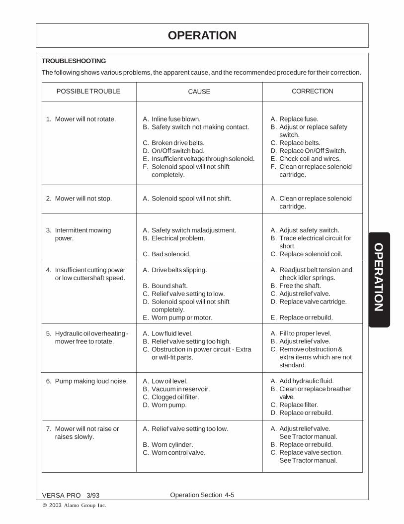
TROUBLESHOOTING
A. Inline fuse blown.B. Safety switch not making contact.
C. Broken drive belts.D. On/Off switch bad.E. Insufficient voltage through solenoid.F. Solenoid spool will not shift
completely.
A. Solenoid spool will not shift.
A. Safety switch maladjustment.B. Electrical problem.
C. Bad solenoid.
A. Drive belts slipping.
B. Bound shaft.C. Relief valve setting to low.D. Solenoid spool will not shift
completely.E. Worn pump or motor.
A. Low fluid level.B. Relief valve setting too high.C. Obstruction in power circuit - Extra
or will-fit parts.
A. Low oil level.B. Vacuum in reservoir.C. Clogged oil filter.D. Worn pump.
A. Relief valve setting too low.
B. Worn cylinder.C. Worn control valve.
A. Replace fuse.B. Adjust or replace safety
switch.C. Replace belts.D. Replace On/Off Switch.E. Check coil and wires.F. Clean or replace solenoid
cartridge.
A. Clean or replace solenoidcartridge.
A. Adjust safety switch.B. Trace electrical circuit for
short.C. Replace solenoid coil.
A. Readjust belt tension andcheck idler springs.
B. Free the shaft.C. Adjust relief valve.D. Replace valve cartridge.
E. Replace or rebuild.
A. Fill to proper level.B. Adjust relief valve.C. Remove obstruction &
extra items which are notstandard.
A. Add hydraulic fluid.B. Clean or replace breather
valve.C. Replace filter.D. Replace or rebuild.
A. Adjust relief valve.See Tractor manual.
B. Replace or rebuild.C. Replace valve section.
See Tractor manual.
1. Mower will not rotate.
2. Mower will not stop.
3. Intermittent mowingpower.
4. Insufficient cutting poweror low cuttershaft speed.
5. Hydraulic oil overheating -mower free to rotate.
6. Pump making loud noise.
7. Mower will not raise orraises slowly.
The following shows various problems, the apparent cause, and the recommended procedure for their correction.
POSSIBLE TROUBLE CAUSE CORRECTION

Operation Section 4-6
OPERATION
VERSA PRO 3/93
© 2003 Alamo Group Inc.
OP
ER
AT
ION
TROUBLESHOOTING (CON'T)
CORRECTIONCAUSEPOSSIBLE TROUBLE
A. Fill in reservoir to sightglass.
B. Tighten fittings.C. Replace filter element.D. Disassemble, inspect, and
repair.
A. See step 1A, 1B, 1C, 2B.B. Disassemble, inspect, and
repair.
A. Remove backplate andexamine surface conditionof flat area; if scored, replacebackplate. Do Not Lap.
B. Disassemble motor examine,condition of shoes on pistons;replace pistons as a completeset if necessary. Do Not Lap.
C. Check relief valve for properpressure setting; adjust orreplace relief valve.
A. Disassemble motor com-pletely. Inspect all parts, cleanall parts, replace all worn partsand flush hydraulic system.
8. System noisy.
9. Sluggish response toacceleration or deceleration.
10. Motor turns while unloadedbut slows down or stopswhen load is applied.
11. Motor will not turn.
A. Air in system due to low oil level.
B. Loose suction line.C. Clogged suction filter.D. Internal pump or motor damage.
A. Air in system.B. Internal pump or motor wear or
damage.
A. Scored back plate.
B. Scored or worn piston shoes.
C. Low relief valve pressure.
A. Severely scored backplate.
12. Excessive case drain flow. A. Excessive internal wear in motor. A. Disassemble motor, inspectparts and replace as neces-sary. Case drain flow shouldnot exceed 1.5 GPM at fullpressure.
12. Mower Heads scalping. A. Center unit Top Link out ofadjustment.
B. Cutting height set to low.
A. Level front unit so that skidshoes are level with ground.
B. Raise cutting height.
R 2-3-94

Maintenance Section 5-1VERSA PRO 04/02
© 2003 Alamo Group Inc.
MAINTENANCESECTION

Maintenance Section 5-2
MAINTENANCE
VERSA PRO 3/93
© 2003 Alamo Group Inc.
MA
INT
EN
AN
CE
DAILY CHECKS
1. Lubricate the VERSA PRO at the specified intervals as outlined in the lubrication diagram. All mower grease
fittings are equipped with lubricaps which snap over the grease fittings to prevent dirt from entering the fittings.
Remove the cap and wipe the fitting before greasing. Wipe the outlet of the grease gun then grease the bearing.
When finished, place the cap over the fitting and wipe any excess grease from around the cap. In extremely dusty
conditions, it is desirable to lubricate more often than every 8 hours. Grease PTO shaft as outlined on the diagram
located on PTO shaft shield. The idler pullies are equiped with a sealed ball bearing and require no further
lubrication. Caster wheel bearings should be repacked at the end of each mowing season and checked before the
start of the next season. The gearbox is shipped with the proper amount of SAE No. 90 extreme pressure lubricant.
Maintain the level of this oil at the lower 1/8" pipe plug on the gearbox cover. LUBRICATE MOWER BEFORE
INITIAL USE.
2. Before each day's use, follow this procedure:
Visually check the unit, and make certain all items are properly tightened.
NOTE: Cutter unit belt tension is maintained by a spring-loaded idler pulley.
Check the reservoir fluid level with the cutter units in the transport position. The oil level should be even with the
sight glass located on the reservoir. Before removing filler cap, wipe the top of the reservoir to prevent dirt from
entering the tank.
NOTE: If the reservoir needs oil, a leak exists somewhere in the system. Repair the leak before using the unit.
Check the cuttershaft to make certain it is fully knived. Replace any missing knives or cotter pins, then run the
unit at full speed to check for vibrations. Do not operate the unit in an out-of-balance condition.
DANGER Before doing maintenance, turn off power, and securely block up mower.

Maintenance Section 5-3
MAINTENANCE
VERSA PRO 3/93
© 2003 Alamo Group Inc.
MA
INTE
NA
NC
E
LUBRICATION INFORMATION
Before operating your Mower, make sure it is properly lubricated and thoroughly inspected. Only a minimum of timeand effort is required to regularly lubricate and maintain this machine to provide long life and trouble free operation.
WARNING! Always disengage the PTO before raising the mower for transporting or making adjustments.
Do not let excess grease collect on or around parts, particulary when operating in sandy areas. The illustrations belowshows lubrication points. All points should be lubricated daily under normal operating conditions. Severe or unusualconditions may require more frequent lubrication. Figure 1.
Use an SAE multi-purpose, lithium-type grease for all location shown. Be sure to clean the fitting thoroughly beforeusing grease gun. Daily lubrication of the wing driveline slip joint is necessary. Failure to maintain proper lubricationwill result in damage to U-joints, gearbox, and / or driveshaft.
FIGURE 1
*NOTE:Lubricate flail roller bearing until lubricantcan be seen coming out betweenroller and bearing housing.
R 03-09-95

Maintenance Section 5-4
MAINTENANCE
VERSA PRO 3/93
© 2003 Alamo Group Inc.
MA
INT
EN
AN
CE
CHANGING HYDRAULIC SYSTEM FILTER
A large capacity filter is located on top of the hydraulic oil reservoir. Figure 2. The filter will trap particles which are.001 inch or larger. The filter needs to be changed after the first 10 hours of operation and every 200 hours thereafter.
FIGURE 2
AIR BREATHER
RETURN OIL FILTER

Maintenance Section 5-5
MAINTENANCE
VERSA PRO 3/93
© 2003 Alamo Group Inc.
MA
INTE
NA
NC
E
CHANGING HYDRAULIC SYSTEM FILTER (cont'd)
1. Clean the filter cover to prevent dirt from entering tank.
2. Loosen the four bolts on the filter cover. Figure 3. Remove one bolt from the filter to aid in removing the filtercover. Figure 4.
3. Push the filter cover down and slowly twist the filter cover off. Figure 5.
4. Remove filter spring. Figure 6.
FIGURE 5
FIGURE 4
FIGURE 3
FIGURE 6

Maintenance Section 5-6
MAINTENANCE
VERSA PRO 3/93
© 2003 Alamo Group Inc.
MA
INT
EN
AN
CE
CHANGING HYDRAULIC SYSTEM FILTER (cont'd)
5. Remove filter. Inspect material trapped by the filter. It can indicate parts wear in the system. Figure 7.
6. Install the new filter.
7. Reinstall filter spring and filter cover. Replace the one bolt which had previously been removed. Tighten all boltsin an even manner. Figure 8.
FIGURE 7
FIGURE 8

Maintenance Section 5-7
MAINTENANCE
VERSA PRO 3/93
© 2003 Alamo Group Inc.
MA
INTE
NA
NC
E
GENERAL
Mowing is accomplished by a series of knives which rotate at high speed on a shaft. The shaft is driven by a hydraulicmotor through a set of drive belts. Belt tension is maintained by a spring-loaded idler pulley.
The cutter unit is mounted to the lift frame by two mounting pins and held in place by a hydraulic cylinder. Thiscylinder is used to tilt the cutter unit to allow mowing on an angle and tilting to the vertical position for transporting.
The cutter unit rides on a large roller assembly. The position of this roller is adjustable and will determine the cuttingheight of the knives.
FIGURE 10
FIGURE 9
3
REPLACING CUTTER UNIT DRIVE BELTSFigure 9.
ADJUSTING CUTTING HEIGHTFigure 10.
1. Lower cutter unit to ground.
2. Place lifting device (scissors jack, hydraulic jack)under center of cutter housing.
3. Remove hex nuts, washers and carriage bolts frombracket at each end of roller. Make certain that rollerbracket is free to move once the fasteners are removed.A stuck roller could drop suddenly and cause an injury.
4. Use lifting device to reposition cutter housing todesired cutting height. Align bracket holes with cutter-housing holes, then reinstall fasteners.
5. Lower cutter unit to ground; then remove lifting device.
1. Place unit on ground or support securely.
2. Remove belt guard.
3. Remove idler arm spring.
4. Remove extension shaft housing mounting bracketfront bolt and loosen rear bolt.
5. Loosen extension shaft housing mounting bracketrear bolt.
6. Pivot extension shaft housing mounting bracketassembly. Remove old belts and install new ones.
7. Reinstall front mounting bolt then secure extensionshaft housing mounting bracket to unit.
8. Reinstall idler arm spring and belt guard.
5
4

Maintenance Section 5-8
MAINTENANCE
VERSA PRO 3/93
© 2003 Alamo Group Inc.
MA
INT
EN
AN
CE
ROLLER BEARING REPLACEMENTFigure 11.
1. Remove roller and both bearing and bracket assemblies from mower. Lift the mower only high enough to removethe roller assembly.
CAUTION: Securely support mower while removing and installing roller assembly.
DETAIL OFROLLER BEARING
FIGURE 11
If installing a roller with preassembled bearing and bracket assemblies, remove the old roller, proceed to step 11.
2. Slide bearing and bracket assemblies off each end of roller.
If replacing with new bearing and bracket assemblies, proceed to step 9.
3. Remove roller bearing and housing assembly attaching hardware. Remove assembly from bracket. Inspectseal between assembly and bracket for brittleness, cracks, wear and tear. Replace if necessary.
If replacing with new roller bearing and housing assemblies, proceed to step 8.
4. Remove grease fitting from the top of bearing housing.
5. Remove bearing form housing. By rotating Bearing 90O sideways and line up with notches in Bearing Housing;then pull out.
6. Install new bearing into housing. Bearing must be installed with grease hole in bearing aligned with grease fittinghole in housing.
7. Reinstall grease fitting to housing. Grease fitting must be tight and seated in grease hole in bearing to preventbearing from rotating in housing.
8. Attach roller bearing and housing assembly to bracket with seal between housing and bracket.
9. Slide bearing and bracket assemblies on each end of roller.
10. Check bearing for proper installation in housing by gently rocking bearing and bracket assembly in end of roller.Play should be slight to none at all.
11. Install roller and bearing and bracket assemblies on mower.
12. Lubricate roller bearing until lubricant can be seen coming out between roller and bearing housing.
R 03-09-95

Maintenance Section 5-9
MAINTENANCE
VERSA PRO 3/93
© 2003 Alamo Group Inc.
MA
INTE
NA
NC
E
CUTTERSHAFT BEARING REPLACEMENT
FIGURE 12
OUTBOARD BEARING. FIGURE 12
1. Lift cutter unit to maximum horizontal height; then, securely support ends of cutterhousing.
2. Remove enough knives to place a floor jack under center of cuttershaft.
3. Securely support cuttershaft.
NOTE: The cuttershaft must remain supported while changing bearings.
4. Remove outboard fender.
5. Remove fasteners securing bearing and housing assembly to cutterhousing; then remove bearing and housingassembly.
NOTE: There are two tapped holes in the housing which can be used to pull bearing and housing assembly out by using special tool No. 701627.
6. Using a jack to align parts, install bearing and housing assembly to cutter unit and make certain that bearingsetscrew is located in keyway on cuttershaft. Grease bearing and install cap over fitting.
If only the outboard bearing and housing assembly is to be replaced, proceed as follows: Remove jack and checkshaft rotation. Reinstall knives which were removed. Reinstall outboard fender. Remove supports. Lower unit toground and test unit.
If the inboard (drive) bearing is to be replaced, proceed to step 7.

Maintenance Section 5-10
MAINTENANCE
VERSA PRO 3/93
© 2003 Alamo Group Inc.
MA
INT
EN
AN
CE
CUTTERSHAFT BEARING REPLACEMENT (cont'd)
NOTE: It is recommended that cuttershaft bearing and housing assemblies be replaced when replacing cuttershaft.
1. Place unit on the ground or securely support at a convenient height.2. Remove cuttershaft bearing and housing assemblies as outlined above. After removing both assemblies, thecuttershaft can be removed and a new one installed. It may be necessary to remove two sets of knives nearest thedrive end of cuttershaft.3. Install new bearing and housing assemblies.
FIGURE 13 FIGURE 14
INBOARD (DRIVE) BEARING. FIGURE 13 & 14.
7. Remove Belt Guard.8. Remove spring from idler arm.9. Remove extension shaft housing mounting bracket fasteners at the cutterhousing. Pivot mounting bracketassembly and remove drive belts.10. Remove fasteners that secure pulley to cuttershaft. Remove pulley and key.11. Remove fasteners securing inboard bearing and housing assembly to cutterhousing; then, remove bearing andhousing assembly.
NOTE: There are two tapped holes in the housing which can be used to pullbearing and housing assembly out by using special tool No. 701627.
12. Using a jack to align parts, install inboard bearing and housing assembly to cutter unit. Grease bearing andinstall cap over fitting.13. Reinstall key and pulley. Secure with cuttershaft fasteners.14. Remove jack and check shaft rotation. Reinstall knives which were removed.15. Reinstall drive belts then secure motor mounting bracket to cutterhousing.16. Reinstall idler arm spring.17. Reinstall belt guard.18. Remove supports, lower unit to ground and test unit.Reinstall outboard fender, if not already installed.
CUTTERSHAFT REPLACEMENT

Maintenance Section 5-11
MAINTENANCE
VERSA PRO 3/93
© 2003 Alamo Group Inc.
MA
INTE
NA
NC
E
Changing to Forward or Reverse Rotation
TORQUE TO 20 FT-LBS
FIGURE 15
WING MOWERS
The hydraulic wing motors are dual rotation motors which means they will rotate in either direction depending onthe inlet port used. An arrow on the flat surface of the motor housing at both ports indicate the direction of rotation.To change rotation, remove the four bolts that mount the manifold block to the motor. Remove the case drain hoseat the motor, but leave it attached in present location at the manifold block. Leave all other plumbing as presentlyinstalled at the manifold block. Remove the two mounting bolts at the motor mounting plate and rotate the motor180 deg. This changes the present inlet port into the outlet port of the motor. Re-install manifold block but do notchange the position. Install case drain hose.
CENTER MOWER
To change direction of cuttershaft rotation for the center mower, three parts are required. A belt guard, an outboardbearing plate and a idler pulley arm. (Consult parts book for these part numbers). Remove the cuttershaft and turn180 deg. remove the gearbox cuttershaft drive pulley and outboard bearing plate, (using the proper bearing plate)mount the plate to opposite side of mower housing. Remove the four bolts that mounts the gearbox and rotategearbox 180 deg. to new position. Install cuttershaft pulley, gearbox output pulley, idler arm pulley assembly andbelt. REPLACE EXISTING BELT GUARD WITH PROPER GUARD.
Replacing Cutter Unit Knives
The cutter knives are attached to the cutter shaft with hardened pin and cotter pins. These pins are supplied withthe knife kit. To remove existing knives, remove and discard these pins and install new knives using new pins.Figure 15.
FOR FORWARD ROTATION: On the right wing and center unit, all knife pins must be installed with their headsfacing away form the cuttershaft pully. On the left wing, the heads of the knife pins must face the cuttershaft pulley.
FOR REVERSE ROTATION: On the right wing and center unit, all knife pins must be installed with their headsfacing toward the cuttershaft pully. On the left wing, the heads of the knife pins must face away from the cuttershaftpulley.

Maintenance Section 5-12
MAINTENANCE
VERSA PRO 3/93
© 2003 Alamo Group Inc.
MA
INT
EN
AN
CE
HYDRAULICS
GENERAL
VERSA PRO hydraulic system consists of two circuits. The power circuit drives the cuttershaft. The control circuitlifts and tilts the cutter unit.
NOTE: It is important that pipe thread sealant be used on solid connections only; never on connections betweenswivel fittings or fittings with "O" rings and straight threads. Use pipe thread sealing compound. DO NOTsubstitute other types of sealant, such as teflon tape, paint, shellac, etc.
INITIAL START-UP PROCEDURES
Whenever the hydraulic system is drained in order to service a hydraulic component, the following start-upprocedure should be completed.
1. Check all nuts and bolts to be sure they are tight and that all lock washers are fully compressed.
2. Check all hoses and hydraulic connections to be sure that they are tight.
3. Inspect all moving parts, and make certain that no wires or hoses will be caught or pinched when the tractor isin operation.Secure all wires and hoses.
4. Thoroughly lubricate the VERSA PRO. Refer to Illustration 1, Page 5-3.
5. Change the hydraulic filter and fill the reservoir to the sight glass with new hydraulic oil. Refer to 2-5 forspecifications.
CAUTION: Remove all objects from, and stand clear of, the front of the cutter unit.DO NOT GET NEAR ROTATING KNIVES!
6. Turn mowers off, then start tractor and run engine at low idle. Operate the cylinder, (turn cutter units on ONLYwhen mowers are fully lowered). Operate until the system is fully charged. Recheck the fluid level and add oil, ifnecessary. If undue noise continues after the system is fully charged, stop the unit and determine the cause.
7. After the hydraulic system is fully charged and functioning properly, switch the mowers on and increase theengine speed to run the PTO at 540 RPM. Maintain this speed for 5 minutes and look for any leaks or possibleproblems.

Maintenance Section 5-13
MAINTENANCE
VERSA PRO 3/93
© 2003 Alamo Group Inc.
MA
INTE
NA
NC
E
HYDRAULIC PUMPS
The pump unit assembly is made up of the oilreservoir,gearbox, and hydraulic pump. The pump isdriven by the Tractor PTO through a drive shaft.Therefore, oil is being pumped whenever the PTO isengaged. When the mower is off, oil is directed tothe reservoir by the solenoid motor control valve anddoes not flow to the cutter motor. Cooling is providedby patented in frame cooling tubes in the wing mow-ers.
eliminate excessive fluid in the pump. All excess fluid in the pump is routed back to the reservoir through the casedrain.
Replacing Outer Pump:
1. Remove the Pump Cover by unscrewing the wing nut which holds it in place.
2. Disconnect the outer Pump Suction Hose, Case Drain Hose, and the Pressure Hose.
NOTE: Clean spills at once. Cap all hoses immediately to prevent contamination of the hydraulic system.
3. Remove the two bolts which attach the outer pump to the inner pump flange.
4. Remove Pump. Lightly oil new "O" Ring and place on inner pump flange. Install the new Pump with the pumpdrain ports facing Hydraulic Tank.
5. Reinstall hydraulic hoses. Tighten hose fittings to their proper torque. Refer to Torque Chart.
6. Reinstall Pump Cover and tighten the four thumb screws securely.Replacing Inner Pump:
7. To replace inner pump both pumps must be removed. Follow same procedure as for outer pump. BE SURETO CAP ALL HOSES AND CLEAN OIL SPILLS AT ONCE.
NOTE: Clean spills at once. Cap all hoses immediately to prevent contamination of the hydraulic system.
8. Separate the inner pump from the outer pump and install new pump to inner pump following step 4 making sureboth case drain ports are facing hydraulic reservoir.
9. Reinstall pumps to pump mounting bracket.
10. Reinstall all hoses. Tighten hose fittings to their proper torque refer to torque chart.
11. Reinstall all guards.
REPLACING HYDRAULIC PUMPS (FIGURE 16)
The pump unit for the power circuit is a piston fixed displacement pump (see specifications) and is PTO driven.It is mounted on the mainframe above the hydraulic reservoir. There is a separate pump for each wing. By followingthe hose routing, the operator can determine each wing mower's supply source. Each pump has a case drain to
FIGURE 16

Maintenance Section 5-14
MAINTENANCE
VERSA PRO 3/93
© 2003 Alamo Group Inc.
MA
INT
EN
AN
CE
SOLENOID CONTROL VALVE (FIGURE 18)
A. CONTROL VALVE
B. SOLENOID
The solenoid control valve directs oil flow from thehydraulic pump. When the mower ON/OFF switch is in the"ON" position, the solenoid is energized and the spoolwithin the valve is positioned to direct oil to the cuttershaftmotor.
When the mower ON/OFF switch is in the "OFF" position,oil pressure within the valve pushes the spool back whichallows the oil to circulate through the cutter unit beforereturning to the reservoir. When the flow of oil to the motor
RESERVOIR (Figure 17)
The reservoir stores hydraulic system oil. The breather cap which is mounted on top of the reservoir preventsa pressure buildup or vacuum from occurring in the tank as oil level changes. Their is also an oil filler cap whichis used to fill the reservoir with oil. To help prevent dirt from entering the tank, clean the top of the reservoir beforeremoving the cap. THE BREATHER CAP HOLDS APPROX 11 PSI PRESSURE IN TANK. REMOVE FILLER CAPSLOWLY
The oil level sight glass is located on the side of the reservoir. The oil level should be even with the sight glass andchecked with the cutter unit in the transport position. The oil temperature should not exceed 180 deg.F.
The oil return hoses are connected to the hydraulic filter on top of the reservoir. Oil is returned from cutter unitcooling tubes and filtered before entering the hydraulic reservoir.
FIGURE 18
FILLER CAP
AIR BREATHER CAP
SIGHT GLASS
FIGURE 17
A
B
R2-16-94

Maintenance Section 5-15
MAINTENANCE
VERSA PRO 3/93
© 2003 Alamo Group Inc.
MA
INTE
NA
NC
E
SOLENOID MOTOR CONTROL VALVE (cont'd)
CHECKING SOLENOID VALVE
a. With engine running, turn the mower ON/OFF switch in the "ON" position. Check voltage level at the solenoid.
b. If it is less than 12 volts, check wiring and ground connections. Checking ground wire is as important as checkingthe hot wire. If voltage is sufficient, the solenoid valve is bad and will need to be replaced.
HYDRAULIC PUMP
DISASSEMBLY
1. Disconnect all hydraulic lines. Remove pump assembly from tractor.
2. Plug all ports and thoroughly clean outside of pump.
3. Clamp the end of the drive shaft in a protected jaw vise with the body of the pump up and remove the sixcapscrews from the back plate.
4. Use a plastic mallet and tap the back plate assembly to loosen it, then pull back plate straight up until it is free.Remove gasket.
5. Remove pump from vise and remove rotating assembly from pump housing.
6. If the pistons did not come out with the piston block, remove them, the spider, and the spider pivot.
7. The piston block assembly need not be disassembled unless the internal pins of spring is damaged.
CAUTION! The following procedure should be used if the spring is to be removed from the piston blockassembly. The spring is highly compressed and the snap ring should not be removed without first
compressing the spring.
The following parts will be needed to disassemble the piston block:
2 ea. 3/8 I.D. x 1-1/8 O.D. flat washer1 ea. 3/8 x 3-1/4 N.C. capscrew1 ea. 3/8 N.C. nut
Place one of the flat washers over the 3/8 x 3-1/4 cap screw and place this through the center of the piston block.Place the other washer over the cap screw and let it rest on the three pins. Screw the nut on and compress thespring inside the piston block. Use a pair of snap ring pliers and remove the internal snap ring. Remove the boltand the two washers. Remove the washers, spring, three pins, and the internal pin keeper.
8. Remove snap ring from housing. Press shaft from housing and remove shaft seal and washer.
9. Remove the two snap rings, thrust bearing, and two thrust washers from the drive shaft.
10. To remove the camplate from housing, remove the four screws from sides of the housing. Remove trunnioncover, seal cover, and o-ring cover. Remove o-ring, seal, two washers, inner race, and needle bearings. The camplate can now be moved over to one side and removed. The cam plate pivot bearing are a loose slip fit into thehousing. Do not be concerned if they are not tight.

Maintenance Section 5-16
MAINTENANCE
VERSA PRO 3/93
© 2003 Alamo Group Inc.
MA
INT
EN
AN
CE
INSPECTION
1. Inspect flat surface of the backplate. The finish on the piston block side should be smooth and free of grooves.DO NOT LAP BACKPLATE WEAR SURFACE. The backplate should be replaced if it shows any of the wearcharacteristics outlined above. Inspect the needle bearing in the backplate. If the needles are free of excessiveplay and remain in the bearing cage, there is no need to replace the bearing.
2. Inspect the piston block. The wear surface that contacts the backplate should be smooth and free of grooves.DO NOT LAP PISTON BLOCK.
3. The pistons should move freely in the piston block bores. If they are sticky in the bore, examine the bore forscoring or contamination.
4. Examine the O.D. of the pistons for finish condition. They should not show wear or deep scratches. The shoesshould be a snug fit on the ball end of the pistons. The flat surfaces of the shoes should be flat and smooth. DONOT LAP THE PISTON SHOES.
5. Examine the spider. It should be flat, no cracks and no signs of wear in the pivot area.
6. Examine the pivot. It should be smooth and show no signs of wear.
7. The cam plate should be inspected for the condition of the finish of the polished shoe surface. It should showno signs of scoring. Inspect the camplate pivot bearings. If the needles are free of excessive play and remain inthe bearing cage, there is no need to replace the bearing.
8. Inspect the drive shaft for fretting in the bearing and spline areas.
9. Inspect the thrust bearing and thrust washers for wear.
10. Inspect the needle bearing in the housing. If the needles are free of excessive play and remain in the bearingcage, there is no need to replace the bearing.
REASSEMBLY
1. Clean all parts in a suitable solvent. Lubricate all critical moving parts before reassembly. If necessary, installnew needle bearing in housing with numbered end of bearing outward.
2. Insert cam plate into housing. Insert needle bearings and inner race. The chamfered I.D. of the race shouldbe inward. Install washers, o-ring seal, o-ring cove, trunnion cover, seal cover, and retain with four screws andtighten to 36-48 in. lbs.
3. Install snap ring on shaft. Install thrust washer, thrust bearing, and second thrust washer. Secure with secondsnap ring.
4. Install shaft in housing and install washer and shaft seal and retain with snap ring.
5. Compress pin keeper and install in the spline of the piston block. Install the three pins with head end to the insideof the block, and install in the special grooves of the piston block spline.
6. Install washer, spring, and second washer in the piston block. Use the two 3/8 I.D. washers and the 3/8 x3-1/4 cap screw to compress the spring and retain with snap ring. Remove the 3/8 x 3-1/4 cap screw and the twowashers.

Maintenance Section 5-17
MAINTENANCE
VERSA PRO 3/93
© 2003 Alamo Group Inc.
MA
INTE
NA
NC
E
7. Install the pivot, spider, and the piston assemblies in the piston block. Install this assembly in the housingassembly. The piston shoes must be in contact with the cam plate. Be sure all the parts are in their proper position.
8. Clamp this assembly in a protected jaw vise with the open end of the housing up.
9. Install new gasket.
10. Install relief valves and springs into backplate.
11. Install backplate assembly. Install sixcap screws and torque to 27-31 ft. lbs.

Maintenance Section 5-18
MAINTENANCE
VERSA PRO 3/93
© 2003 Alamo Group Inc.
MA
INT
EN
AN
CE
HYDRAULIC MOTORDISASSEMBLY
1. Clean outside of unit thoroughly. Refer to Hydraulic Motor illustration in the Parts Listing section.
2. Clamp shaft in a protected jaw vise with backplate end up.
3. Remove six bolts from backplate.
4. Use a plastic mallet and tap the backplate to loosen it.
5. Remove o-ring from backplate.
6. Remove the complete piston block assembly from the housing assembly.
7. Remove piston assemblies, spider, and pivot form piston block assembly.
8. The piston block assembly need not be disassembled unless the pins or spring is damaged.
CAUTION! The following procedure should be used if the spring is to be removed from the piston block. Thespring is highly compressed and the snap ring should not be removed without compressing thespring.“
The following parts will be needed to disassemble the piston block:
2 ea. 3/8 I.D. x 1-1/8 O.D. flat washer1 ea. 3/8 I.D. x 3-1/4 N.C. capscrew1 ea. 3/8 N.C. nut
Place one of the flat washers over the 3/8 x 3-1/4 bolt and place this through the center of the piston block. Placethe other washer over the boltand let it rest on the three pins. Screw nut on and compress the spring inside thepiston block. Use a pair of snap ring pliers and remove the internal snap ring. Remove the bolt and two washers.Remove the two washers, spring, three pins, and pin keeper.
9. Remove thrust race from housing.
10. Remove snap ring from housing.
11. Remove shaft seal from housing.
12. Remove washer from housing.
13. Remove drive shaft from housing.
14. Remove the two snap rings, thrust washers, and thrust bearing, from drive shaft.
INSPECTION
1. Wash all parts thoroughly in a suitable solvent.
2. Examine needle bearings in housing and backplate.
3. Inspect thrust washers and thrust bearing. All surfaces should be free of any signs of wear or fretting.
4. Inspect spider and pivot; conical surfaces should be free of wear and score marks.

Maintenance Section 5-19
MAINTENANCE
VERSA PRO 3/93
© 2003 Alamo Group Inc.
MA
INTE
NA
NC
E
5. Inspect the pistons: the O.D. surface should be smooth and free of scoring. The shoes should be snug fit tothe piston. The face of the shoes should be flat and free of scoring and flaking. DO NOT LAP PISTONSHOES.
6. Inspect the piston block; the bores should be free of scoring. The surface that contacts the backplate shouldbe smooth and free of grooves or metal build-up. Do not lap piston block.
7. Inspect the thrust race; the surface should show no signs of scoring or grooves.
8. Inspect the flat surface on the backplate; it should be free of excessive scoring or metal build-up. DO NOT LAPBACKPLATE.
9. Inspect the drive shaft for fretting in the bearing areas. Check spline area for twisted or broken teeth. If keyedshaft, check for cracked or chipped keyway.
REASSEMBLY
1. Use filtered system oil to lubricate all critical moving parts before assembly.
2. Install one snap ring in rear groove of drive shaft. Install one thrust washer, thrust bearing, and second thrustwasher on drive shaft. Install second snap ring in front groove on drive shaft.
3. Replace needle bearing in housing if necessary. Install shaft in housing assembly and install washer. Oil O.D.of new shaft seal and press into position. Retain with snap ring.
4. Compress pin keeper and install in the spline area of the piston block.
5. Install the three pins in the special grooves of the spline and with head end of pin toward inside of bock.
6. Install one washer, spring, and second washer. Use the two 3/8 I.D. washers and the 3/8 x 3-1/4 capscew tocompress the spring and retain with snap ring. Remove the 3/8 x 3-1/4 capscrew and two washers.
7. Install the pivot, spider, and the piston assemblies in the piston block assembly.
8. Lubricate thrust race and install in housing assembly.
9. Install piston block assembly in housing assembly. The piston shoes must contact the thrust race. Be sure allparts are in their proper position.
10. Install new needle bearing in backplate if necessary.
11. Install new o-ring on backplate.
12. Install backplate on housing.
13. Install six capscrews and torque 15-18 ft. lbs.
14. On through shaft type assembly, install shaft seal and snap ring in backplate. Install key in drive shaft.

Maintenance Section 5-20
MAINTENANCE
VERSA PRO 3/93
© 2003 Alamo Group Inc.
MA
INT
EN
AN
CE
LIFT CYLINDERS (FIGURE 19)
FIGURE 19
Cylinder
Cylinder
DISASSEMBLY OF LIFT CYLINDER
For part numbers and illustration, refer to the Parts Listing section.
1. Disconnect hoses at cylinder. Cap all hoses to prevent fluid contamination. Remove cylinder from unit.
2. Remove reducer bushing and snap ring which retains the rod guide. Remove rod guide, rod, and piston. Remove
guide and piston from rod.
3. Replace all "O" rings, back-up washers, and rod wiper. Inspect rod, guide, piston, and body for damage.
4. Clean inside of cylinder with mineral spirits. DO NOT wipe dry; air dry instead. Lint, dirt, and, grit can cause
immediate or premature failure.
5. Lubricate all parts with clean hydraulic oil and reassemble.
6. Reinstall cylinder with stop located on the upper side, to prevent bending the rod.
R 12-30-98

Maintenance Section 5-21
MAINTENANCE
VERSA PRO 3/93
© 2003 Alamo Group Inc.
MA
INTE
NA
NC
E
EXTERNAL COILSLIP CLUTCH DISK REPLACEMENTA. TO DISASSEMBLE EXTERNAL COIL SPRING CLUTCH (Refer to FIGURE 20)
Before beginning disassembly, remove or fold shields out of the way and clean off dirt and trash from thearea.1. Remove two Attaching Bolts (6). Remove Clutch Assembly from shaft of Gearbox. Leave
Driveline or Driveline Half attached to Clutch.2. Loosen six Adjusting Bolts (1). LOOSEN EACH BOLT A FEW TURNS AT A TIME - NOT ALL
AT ONCE. Continue in rotation until Nuts are loose. Remove these Bolts. Flange Yoke (9) willslide off. On Clutches that have Dust Shields (11), Shields will slide off with Flange Yoke. Note:Some types do not have Dust Shields.
3. On the opposite side, Outer Flange (2) will slide off which will allow Clutch Plate (3) to slide overnotches on outside diameter of Clutch Body (5).
4. Remove Plate with six bolt holes (7). Note: Bolts (1) go through these holes.5. Remove the four Friction Disks (4) and discard. DO NO RE-USE.
B. TO CLEAN AND INSPECT1. Inspect all components for rust, wear, or damage. Check Spacer (8) for scoring or excessive
wear. Clean Clutch Plates and Drive Plates with a wire brush as required to remove any rust.
C. TO REASSEMBLE (Refer to Figure 20)1. After all parts have been inspected, cleaned or replaced as necessary, replace components in
reverse order from disassembly USING THE NEW, IMPROVED DISKS. Do not tighten the sixAdjusting Nuts and Bolts (1) until assembly is complete.
D. TO ADJUST (Refer to Figure 21)1. To adjust Slip Clutch, tighten Bolts (1) until the Nut makes contact with Compression Spring (10).2. After all six Bolts have been assembled so that Nuts contact Springs, mark the position of the
top flat on each Nut.. Tighten Nuts 1-3/8 turns as follows:Do NOT tighten one bolt completely. Tightening as shown in rotation will put equal pressure allthe way around on Friction Disks and Drive Plates.a. Tighten the Nuts (1) one-half turn in rotation.b. Tighten one-half turn again until the marks on the Nuts are on top as in the beginning.c. Then, carefully tighten 3/8 of a turn. As a double check, the Springs should now be
COMPRESSED TO 1-11/32" (1.34") TO 1-5/16" (1.31") long. SEE FIG 21.3. Re-assemble Clutch to Gearbox. Tighten Bolts (6) securely.4. If Clutch slips too easily, STOP PTO AT ONCE. Tighten each Adjusting Nut (1) NO MORE THAN
¼ TURN AT A TIME. NEVER TIGHTEN SPRINGS SHORTER THAN 1-9/32" (1.28") LONGEVEN AFTER DISK WEAR.
NOTE:EXCESSIVE SLIPPING WILL BURN UP DISKS AND SLIP CLUTCH TO THE POINT WHERETHE CLUTCH IS NOT REPAIRABLE. HOWEVER, EXCESSIVE TIGHTENING WILL PREVENTTHE SLIP CLUTCH FROM SLIPPING AND CAN LEAD TO FAILURES OF DRIVETRAINCOMPONENTS WITH RESULTING DOWNTIME.
E. TO REPLACE SHIELDS1. Make certain that all Driveline Canopy Shields are in good repair and rotate smoothly on the
Drivelines. Replace Bearings and/or Integral Shields if necessary.2. Re-install Gearbox Canopy Shields with the same hardware and tighten securely.

Maintenance Section 5-22
MAINTENANCE
VERSA PRO 3/93
© 2003 Alamo Group Inc.
MA
INT
EN
AN
CE
FIGURE 20SPRING CLUTCH FIGURE 21
SLIP CLUTCH ADJUSTMENT
SLIP CLUTCH PRECAUTIONSIf MOWER is to sit outside FOR 30 DAYS or moreand be exposed to rain or humid air, the CLUTCHESshould be removed and STORED IN A DRY AREA.
However, if CLUTCHES are left outside for 30days or more, make certain that you follow BREAK-A-WAY INSTRUCTIONS shown below.
It is very important to check for and FREE-UPEVERY FROZEN CLUTCH to prevent drivetrain’soverloading and possible failure of drivetrain ortractor components.
A. TO TEST FOR FROZEN CLUTCHES:
1. Mark across Clutch Disks and Plates plainly with soft chalk so that you can tell if Clutch slips(would mis-align the marks).
2. With mower lifted off the ground, PTO engaged, and tractor engine at half throttle, let the tractorclutch out rapidly to see if all Slip Clutches will slip.
3. If all Clutches slip and provide protection for the drivetrain, you are ready to mow if you haveperformed all normal maintenance.
B. IF MACHINE IS STORED OUTSIDE FOR 30 DAYS OR MORE:
1. Before mowing, back off all Adjusting Nuts (1) until Nuts just touch Springs (10). Then, tightenNuts one full turn uniformly.
2. Mark Plates and Disks as in A.1. above. With PTO engaged and tractor running at HALFTHROTTLE, let Clutch out rapidly to “pop” Slip Clutches loose. If all Slip Clutches slip as isnecessary, adjust as is shown at “D” on other side, and you are ready to mow if you havecompleted all normal maintenance.
1-5/16" Standard1-3/16" Min.FRICTION
DISC (TYP)
CLUTCHPLATE
SPRING BOLTWITH NUT
ITEM PART NO. QTY DESCRIPTION
1 00754302 1 Flange Yoke2 00755599 1 Clutch Support3 00766810 1 Pressure Plate4 00754314 2 Plate with Holes5 00754202 4 Lining Ring6 00754301 1 Bushing7 00754303 8 Spring8 00755600 2 Nut & Bolt9 00754199 8 Nut & Bolt
8 Nut & Bolt10 00754201 1 Intermediate Plate
R 04-26-99

Maintenance Section 5-23
MAINTENANCE
VERSA PRO 3/93
© 2003 Alamo Group Inc.
MA
INTE
NA
NC
E
ATTENTION!!Buy clean Dextron II AT Oil and keep it clean. Always clean off filler area and pour new oilthrough a filter.
VERSA PROTANK FILLING INSTRUCTIONS
USE Universal Tractor Hydraulic oil only.
A VERSA PRO will require approximately 26 gallons of oil to fill the hydraulic tank, hoses, and cooling tubes in themower deck. The Hydraulic tank only holds 15 gallons of oil and you can not add enough oil to the tank the firsttime to completely fill the system. Therefore, the following filling instructions must be carefully followed to preventpump cavitation and instant pump failure.
1. After the VERSA PRO mower is completely assembled to the tractor and with the wings on the ground, fillthe mower hydraulic tank above the oil level sight gauge approximately 1" below the top of the tank.UseUniversal Tractor Hydraulic Oil only.
2. Start the tractor and engage PTO for 30 to 45 seconds and then turn it off.
3. Check the oil level in the sight gauge. If no oil is seen, add oil to bring the level up to the sight gauge.
NOTE!! Do not fill the tank with oil above the level of the sight gauge after the first filling. Over-filling thetank with oil after the initial filling may result in oil being discharged through the air filter on top of thehydraulic tank.
4. Start the tractor and engage PTO for 2 minutes and then turn it off.
5. Again check the oil level in the sight gauge. If the oil level is in the sight gauge, the unit is ready to run.If no oil is seen, add oil to bring the level up to the sight gauge.
6. Repeat steps 4 and 5 as required until the oil level stabilizes at the level of the sight gauge.
R 9-25-00

Maintenance Section 5-24
MAINTENANCE
VERSA PRO 3/93
© 2003 Alamo Group Inc.
MA
INT
EN
AN
CE
*
PROPER TORQUE FOR FASTENERS
The chart lists the correct tightening torque for fasteners. When bolts are to be tightened or replaced, refer to thischart to determine the grade of bolts and the proper torque except when specific torque values are assigned inmanual text.
RECOMMENDED TORQUE IN FOOT POUNDS UNLESS OTHERWISE STATED IN THE MANUAL*
NOTE: These values apply to fasteners as received from supplier, dry or when lubricated with normal engine oil.They do not apply if special graphited or molydisulphide greases or other extreme pressure lubricants are used.This applies to both UNF fine and UNC coarse threads.

VERSA PRO 04/02 Parts Section 6-1
© 2003 Alamo Group Inc.
PARTS SECTION

VERSA PRO 06/01 Parts Section 6-2
© 2003 Alamo Group Inc.
PAR
TS
PARTS ORDERING GUIDE
For maximum safety and to guarantee optimum product reliability, always usegenuine Alamo. The use of inferior replacement parts may cause premature orcatastrophic failure which could result in serious injury or death. Direct anyquestions regarding parts to:
The following instructions are offered to help eliminate needless delay and error in processingpurchase orders for the equipment in this section.
1. The Parts Section is prepared in logical sequence and grouping of parts that belong to the basicmachine featured in this manual. Part Numbers and Descriptions are given to help locate the partsand quantities required.
2. The Purchase Order must include the name and address of the person or organization orderingthe parts, who should be charged, and if possible, the serial number of the machine for which theparts are ordered.
3. The Purchase Order must clearly list the quantity of each part, the complete and correct partnumber, and the basic name of the part.
4. The Manufacturer reserves the right to substitute parts where applicable.
5. Some parts are unlisted items which are special production items not normally stocked and aresubject to special handling. Request a quotation for such parts before sending a Purchase Order.
6. The Manufacturer reserves the right to change prices without prior notice.
NOTE:Please refer to The Safety Section in the front of this Manual for the proper PartNumber when ordering Replacement Safety Decals.
Alamo Industrial1502 E. WalnutSeguin, Texas 78155830-372-3551

VERSA PRO 06/01 Parts Section 6-3
© 2003 Alamo Group Inc.
PAR
TS
Mainframe Assembly ....................................................................................................................... 6-4
Wing Lift Assembly .......................................................................................................................... 6-5
Center Lift Assembly ........................................................................................................................ 6-6
Tilt Cylinder Assembly ..................................................................................................................... 6-7
Hydraulic Cylinder Assembly ........................................................................................................... 6-8
Driveline ........................................................................................................................................... 6-9
Slip Clutch ....................................................................................................................................... 6-11
Speed Increaser Replacement Parts ................................................................................................ 6-12
Tandem Front Pump Assembly ........................................................................................................ 6-14
Wing Mower Assembly .................................................................................................................... 6-16
88" Center Mower Assembly ............................................................................................................ 6-20
96" Center Mower Assembly ..................................................................................................... 6-26
Reverse Gearbox .............................................................................................................................. 6-32
Mainframe to Attachment Frame ...................................................................................................... 6-33
Tank Assembly ................................................................................................................................ 6-34
Left Wing Hydraulic Motor Assembly ............................................................................................... 6-35
Right Wing Hydraulic Motor Assembly ............................................................................................. 6-36
Hydraulic Motor ................................................................................................................................ 6-37
Caster Wheel Assembly .................................................................................................................. 6-38
Hydraulic Schematic ........................................................................................................................ 6-40
Cable Mount Plate ........................................................................................................................... 6-41
Optional Equipment & Packages ............................................................................................... 6-42
TABLE OF CONTENTS

VERSA PRO 04/02 Parts Section 6-4
© 2003 Alamo Group Inc.
PAR
TSMAINFRAME ASSEMBLY
ITEM PART NO. QTY DESCRIPTION
17 108094 1 Weld. - Overarm (RH)18 108093 1 Weld. - Overarm (LH)19 00756793 2 Bolt20 001600 1 Pump21 00755153 3 Cotter Pin22 000552 8 Shim23 00756655 4 Parking Jack24 5F8130 1 Wing Nut25 00762689 1 Spacer26 107795 1 Weldment - Bracket27 002306 1 Splined Adapter28 00003500 2 Grease Fitting33 02965449 2 Roll Pin34 107970 1 Collar35 107971 1 Collar36 107750 1 Mainframe Weldment
Rev 04-11
ITEM PART NO QTY DESCRIPTION
1 107762 1 Weld. - Mnt. Plate2 02897900 1 Speed Increaser3 02036400 4 Bolt4 107969 1 Shaft5 00019600 2 Lockwasher6 00748823 2 Bolt7 107772 1 Cover8 00001800 4 Nut9 002475 1 Top Link10 8354 1 Pin12 0008300 12 Bolt13 00695100 12 Nut14 02822500 3 Flatwasher15 103266 1 Pin16 108098 1 Weld. - A-Frame
3335
33
34

VERSA PRO 04/02 Parts Section 6-5
© 2003 Alamo Group Inc.
PAR
TS
WING LIFT ASSEMBLY
16
17
SAFETY SWITCH DETAIL
18
1920
ITEM PART NO QTY DESCRIPTION
1 02965828 1 Weldment w/Bushing - Lift Frame (LH)02965825 1 Weldment w/Bushing - Lift Frame (RH)
2 02964991 2 Weldment - Link3 02965212 2 Bearing4 02965213 2 Bearing5 00748823 4 Bolt6 00002700 8 Flatwasher7 103266 2 Pin7A 02965074 2 Pin8 107769 1 Weldment - Actuator (LH)
107770 1 Weldment - Actuator (RH)9 00001800 6 Nut10 00763355 2 Pin11 02965829 2 Pin12 00764656 4 Bushing13 02965777 4 Pivot pin14 000760 2 Nut15 00755153 2 Cotter Pin16 002020 4 Spacer17 002019 2 Magnet18 703520 2 Switch19 02963585 8 Machine Screw20 02963584 8 Locknut21 02965214 4 Bushing22 02822500 4 Washer27 00755082 2 Bolt
A

VERSA PRO 04/02 Parts Section 6-6
© 2003 Alamo Group Inc.
PAR
TS
CENTER LIFT ASSEMBLY
ITEM PART NO QTY DESCRIPTION
1 107708 2 Anti-sway bar2 7A14932 1 Bolt3 5JRC1490 1 Nut4 001681 2 Flange Bearing5 108118 1 Roller Bracket LH
108117 1 Roller Bracket RH6 00022500 4 Bolt7 02957941 4 Locknut8 00750479 2 Bolt9 02030300 2 Nut10 107728 2 Cylinder11 02027400 2 Bolt12 00001800 4 Nut13 8354 2 Pin14 02822500 2 Flatwasher15 00755153 2 Cotter Pin16 00748823 4 Bolt17 107759 1 Weldment - Roller18 703952 2 Lower Link (Includes Item #4)19 00756655 4 Parking Jack20 02959892 6 Bushing
4
164 5
6
7

VERSA PRO 06/01 Parts Section 6-7
© 2003 Alamo Group Inc.
PAR
TS
123412341234
1
2
3 4
5
67
15 16
1713
18
19
202110
14
12
9
12
ITEM PART NO. QTY DESCRIPTION
1 02961483 1 Hydraulic Cylinder2 02962134 1 Gland3* -------- 1 “O” Ring4 02962137 1 Rod Assembly5 02962136 1 Barrel Assembly6 02962131 1 Piston7 02840500 1 Locknut8 02962181 1 Adapter9 02963095 1 Pin10* -------- 1 Buffer Seal11 02960054 1 Breather Plug12 00606000 2 Cotter Pin13* -------- 1 Back-Up Ring14 02962129 1 Collar15* -------- 1 Wear Ring16* -------- 1 Piston Seal17* -------- 1 “O” Ring18 02962169 1 Set Screw19 02962170 1 Nylon Insert20* -------- 1 Rod Wiper21* -------- 1 Rod Seal* Included in Seal Kit P/N 02962135
TILT CYLINDER ASSEMBLY
1234
123412341234
12345
118

VERSA PRO 06/01 Parts Section 6-8
© 2003 Alamo Group Inc.
PAR
TS
ITEM PART NO. QTY DESCRIPTION
1 107728 1 Hydraulic Cylinder2 02962145 1 Gland3 108226 1 Wldmt.-Cylinder Rod4 02962143 1 Barrel Assembly5 02962125 1 Piston6 02247100 1 Locknut7 02960018 1 Elbow8 00753013 Ref. Bolt9 8354 1 Pin10 02845800 Ref. Bolt11 00749137 Ref. Nut12 02959892 2 Bushing13 02962146 1 Collar14 02962169 1 Set screw15 02962170 1 Nylon insert16 02960054 1 Breather plug17 00755153 1 Cotter Pin18 02822500 1 Flatwasher
Seal Kit 02962147
HYDRAULIC CYLINDER ASSEMBLY
R 12-30-98

VERSA PRO 06/01 Parts Section 6-9
© 2003 Alamo Group Inc.
PAR
TS
DRIVELINE P/N 002470
1211 4 10
6 78
97
53 4 213
ITEM PART NO. QTY. DESCRIPTION
1 0921000320 1 Yoke, Q.D. 1-3/8 6B Spline2 0921000312 2 Cross Kit3 0921000371 1 Yoke4 0921000333 1 Yoke5 0901000372 1 Tube6 0921000341 1 Shield Cone, 6 Rib7 0921000343 2 Bearing Ring8 0901000394 1 Inner Shield Tube9 0901000344 1 Outer Shield Tube10 0901000332 1 Tube11 0921000331 1 Yoke12 8983 1 Yoke, Slide Collar 1-3/8 - 6B Spline13 8445 1 Slide Collar Repair Kit14 0921000321 1 Q.D. Pin Repair Kit
R 03-08-01
2
14

VERSA PRO 06/01 Parts Section 6-10
© 2003 Alamo Group Inc.
PAR
TS
ITEM PART NO. QTY DESCRIPTION
1 00759948 1 Complete Slip Clutch2 00759517 2 Grease Fitting (Cross Kit)3 00752896 2 Cross Assembly4 00754154 1 Outer Tube Yoke5 00754167 1 Roll Pin6 00760242 1 Outer Tube7 00760243 1 Inner Tube8 00754153 1 Inner Tube Yoke9 00754167 1 Roll Pin10 00757051 1 Yoke 1-3/8" - 611 00754335 1 Grease Zerk (Tube)12 00756004 1 Driveline Warning Label13 00760244 1 Outer Half w/Slip Clutch14 00760245 1 Inner Half Shaft w/1-3/8 - 6 Yoke15 00763196 1 Inner Shield Bearing18 00760250A 1 Complete Shield19 00756005 1 Driveline Shield Warning Label20 00763195 1 Outer Shield Bearing22 00757144 1 Q.D. Collar Kit23 00760248A 1 Half Inner Shield24 00760249A 1 Half Outer Shield25 00754330 3 Bolt, Nylon
DRIVELINE ASSEMBLY P/N 002471
25

VERSA PRO 06/01 Parts Section 6-11
© 2003 Alamo Group Inc.
PAR
TS
SLIP CLUTCH ASSEMBLY
P/N 00759985 P/N 00759985A(Obsolete)
ITEM PART NO. PART NO. QTY DESCRIPTION
1 00754302 1 Flange Yoke2 00755599 1 Clutch Support3 00766810 1 Pressure Plate4 00754314 2 Plate with Holes5 00754202 4 Lining Ring6 00754301 1 Bushing7 00754303 8 Spring8 00755600 2 Nut & Bolt9 00754199 8 Nut & Bolt
8 Nut & Bolt10 00754201 1 Intermediate Plate
00759985
(*Obsolete seenote below)00759985A
*NOTE:This slip clutch is no longer available. Order Spring Kit (P/N 00773222)as replacement part to convert to a spring clutch.
R 04-26-99

VERSA PRO 06/01 Parts Section 6-12
© 2003 Alamo Group Inc.
PAR
TS
SPEED INCREASER REPLACEMENT PARTS P/N 02897900
R 10-27-97
NOTE: ITEM 37,38,39,40 ARE NOT PART OF02897900 SPEED CHANGER.

VERSA PRO 06/01 Parts Section 6-13
© 2003 Alamo Group Inc.
PAR
TS
SPEED INCREASER REPLACEMENT PARTS P/N 02897900
ITEM PART NO. QTY DESCRIPTION
1 02922700 1 Adapter, Shaft
2 00751531 1 Pinion Gear - High Speed
5 00752179 1 Shaft & Gear, Low Speed
6 02922600 1 Pump Flange
7 00751949 1 Cover, Closed
8 00751950 2 Cover, Open
9 00751970 8 Pipe Plug
10 00751535 3 Seal
11 00751954 1 Retaining Ring
12 00751942 1 Breather
13 00751951 1 Bearing Cup
14 00751533 1 Bearing Cone
15 00749201 3 Bearing Cup
16 00749200 3 Bearing Cone
17 00751953 1 Spacer Ring
18 00751955 1 Housing
19 00751956 1 Housing
20 00751957 2 Dowel
21 00751958 1 Gasket (.015)
22 00751971 2 Spacer Ring
24 00751959 AR Shim (.005 Alum.)
25 00751960 AR Shim (.007 Alum.)
26 00751961 AR Shim (.020 Alum.)
27 00751962 3 Shim (.005 Fibre)
28 00751963 AR Shim (.005 Alum.)
29 00751964 1 Shim (.005 Fibre)
30 00751965 AR Shim (.007 Alum.)
31 00751966 AR Shim (.020 Alum.)
32 00751967 24 Screw
33 00751968 24 Lockwasher
34 00751969 8 Screw
35 00013901 8 Nut
36 00012101 8 Lockwasher
00752772 1 Magnetic Plug
*37 107970 1 Collar
*38 107971 1 Collar
*39 02965449 2 Roll Pin
*40 107969 1 Shaft
R 10-27-97* NOT PART OF 02897900 SPEED CHANGER.

VERSA PRO 06/01 Parts Section 6-14
© 2003 Alamo Group Inc.
PAR
TS
*FRONT PUMP ASSEMBLY P/N 001841 - 2.77 Cu. In. Disp.
*REAR PUMP ASSEMBNLY P/N 001840 - 2.77 Cu. In. Disp.
TANDEM FRONT PUMP ASSEMBLY
R 04-26-99

VERSA PRO 06/01 Parts Section 6-15
© 2003 Alamo Group Inc.
PAR
TS
TANDEM FRONT PUMP ASSEMBLY
*FRONT PUMP ASSEMBLYP/N 001841 - 2.77 Cu. In. Disp.
*REAR PUMP ASSEMBLYP/N 001840 - 2.77 Cu. In. Disp.
ITEM PART NO. QTY DESCRIPTION
1 03200402 2 Rotating Kit Assembly
2 001837 1 Back-Up Plate Assy w/
Bearing
3 001838 1 Driveshaft
4 -------- 1 Housing
5 001644 2 Thrust Race & Bearing
6 Seal Kit - Shaft Seal
7 03200408 2 Cam Plate Insert
8 Seal Kit 2 "O" Ring
9 02766400 6 Bolt
10 03200411 2 Washer
11 Seal Kit - Retaining Ring
12 Seal Kit - Retaining Ring
13 001844 2 Bolt
16 002339 2 Bearing, Backplate
17 002340 2 Bearing, Housing
SEAL KIT 001648
ITEM PART NO. QTY DESCRIPTION
1 03200402 2 Rotating Kit Assembly
2 001834 1 Back-Up Plate Assy w/
Bearing
3 001835 1 Driveshaft
4 -------- 1 Housing
5 001644 2 Thrust Race & Bearing
6 Seal Kit - Shaft Seal
7 03200408 2 Cam Plate Insert
8 Seal Kit 2 "O" Ring
9 001836 6 Bolt
10 03200411 2 Washer
11 Seal Kit - Retaining Ring
12 Seal Kit - Retaining Ring
13 001839 1 Coupler
14 001843 1 Lock Ring
15 001842 1 "O" Ring
16 002339 2 Bearing, Backplate
17 002340 2 Bearing, Housing
SEAL KIT 001648
* Refer To Numbers Stamped In Flange To Identify.
No. Stamped in Flange Part No. Description
001600R 001841 Pump Front Section 2.77 CID001600F 001840 Pump Rear Section 2.77 CID

VERSA PRO 06/01 Parts Section 6-16
© 2003 Alamo Group Inc.
PAR
TS
WING MOWER ASSEMBLY
Front Deflector is used only with reverse rotation.Double quantities for front deflector.
R 04-28-95

VERSA PRO 06/01 Parts Section 6-17
© 2003 Alamo Group Inc.
PAR
TS
WING MOWER ASSEMBLY
R 02-10-99
ITEM PART NO. QTY DESCRIPTION
1 107158 1 Right Wing Mower Weldment107159 1 Left Wing Mower Weldment
2 ---------- 1 Hyd. Motor Assy(See Motor Assemblies for correct part numbers)
@ 03200521 1 Key3 106458 1 Motor Mounting Bracket+ 00023100 2 Bolt4 00748823 2 Bolt5 00001800 2 Nut6 00019600 2 Lockwasher7 000673 1 Pulley8 001761 1 Hub+ 10121000 3 Bolt/Hub+ 00011700 3 Lockwasher9 000702 1 V-Belts Matched Pair10 106529 1 Right Idler Arm Forward Rotation@ 106527 1 Right Idler Arm Reverse Rotation@ 106526 1 Left Idler Arm Reverse Rotation
106528 1 Left Idler Arm Forward Rotation11 103105 1 Idler Pulley+ 000001 1 Bolt+ 00011700 1 Lockwasher+ 00023500 1 Washer12 101778 1 Spacer13 000539 1 Spring+ 000001 1 Bolt+ 00011700 1 Lockwasher@ 702747 1 Right Idler Assembly - Forward Rotation@ 702748 1 Left Idler Assembly - Forward Rotation@ 703085 1 Right Idler Assembly - Reverse Rotation@ 703086 1 Left Idler Assembly - Reverse Rotation@ 000206 1 Lubricap14 107390 1 Right Belt Guard Forward Rotation
107394 1 Right Belt Guard Reverse Rotation107386 1 Left Belt Guard Forward Rotation107389 1 Left Belt Guard Forward Rotation
+ 02035400 2 Bolt+ 00011100 2 Lockwasher+ 03101646 2 Flatwasher@ 702754 1 Guard Support+ 00753642 1 Bolt+ 00752036 1 Nut15 103065 1 Cuttershaft Pulley16 103105 1 Key17 103767 1 Washer18 00010300 1 Lockwasher19 000407 1 Bolt20 703695 1 Cuttershaft Bearing & Housing Assembly@ 002315 1 Bearing21 107178 1 Roller-Round,Keyed Shaft
100786 1 Roller-Hex Shaft@ 703260 1 Roller Assembly-Hex, (including 21,71,77,78)+ 000516 2 Carriage Bolt+ 02886900 2 Carriage Bolt+ 00001800 4 Nut29 107125 1 Cuttershaft - Coarse Cut29A 107129 1 Cuttershaft - Fine Cut

VERSA PRO 06/01 Parts Section 6-18
© 2003 Alamo Group Inc.
PAR
TS
WING MOWER ASSEMBLY
R 1-16-08
Front Deflector is used only with reverse rotation.Double quantities for front deflector.
64

VERSA PRO 04/02 Parts Section 6-19
© 2003 Alamo Group Inc.
PAR
TSWING MOWER ASSEMBLY
+Fastener, not shown *Optional @ Not shown
ITEM PART NO. QTY DESCRIPTION
30 108381 88 Coarse Cut Knife30 105319M 88 Coarse Cut Knife - Extreme Service31 102086 216 Fine Cut Knife32 100761 44 Ring33 102670 44 Pin34 02668700 44 Cotter Pin35 02668700 108 Pin36 101034 108 Knife Pin37 103051 2 Shoe Wear Plate38 02886900 2 Carriage Bolt39 000700 4 Plow Bolt+ 00011700 6 Nut40 702749 1 Idler Pivot Pin w/Grease Fitting@ 000853 1 Grease Fitting@ 000206 1 Lubricap44 703271 1 Cuttershaft Bearing & Housing Assembly@ 703694 1 Bearing w/Set Screw45 00753642 6 Bolt47 00752036 6 Nut48 000130 6 Bolt49 000841 6 Lockwasher50 103064 1 Fender51 00748823 1 Bolt52 02030700 1 Bolt54 00001800 2 Nut55 100755 1 Rear Trash Deflector56 10058000 12 Bolt57 00024100 12 Flatwasher59 02959924 12 Nut60 107259 1 Foot Guard61 02030700 2 Bolt@ 00748823 2 Bolt62 108744 1 Bar Flap Retainer - Rear64 00019600 4 Lockwasher65 00001200 4 Nut66 000032 108 Bolt67 02990020 216 Ring Clip68 000210 108 Nut69 101993 216 Ring Knife70 101991 108 Ring71 703575 2 Roller Bearing & Housing Assembly-Keyed
703976 2 Roller Bearing & Housing Assembly-Hex107340 2 Cast Housing Only (No Bearing)
72 703574 2 Bearing & Set Screw-Keyed002486 2 Bearing-Hex
73 002039 2 Grease Fitting74 002037 2 Seal75 000516 4 Carriage Bolt76 00001800 4 Nut77 107182 1 Left Roller Bracket78 107380 1 Right Roller Bracket79 106781 1 Front Trash Deflector@ 703977 1 Left Roller Bracket & Bearing Assy. (Keyed Hex)@ 703596 1 Right Roller Bracket & Bearing Assy. (Keyed Hex)+ 02979042 4 Locknut+ 02886900 2 Carriage Bolt+ 000516 2 Carriage Bolt80 108185 1 Locking Plate81 00720512 2 Bolt82 00725916 2 Center Lock Nut83 108752 2 Bar Flap Retainer - Front

Parts Section 6-20VERSA PRO 06/01
PAR
TS
© 2003 Alamo Group Inc.
88" CENTER MOWER ASSEMBLY

Parts Section 6-21VERSA PRO 06/01
PAR
TS
© 2003 Alamo Group Inc.
ITEM PART# FWD REV DESCRIPTION
1 107171 1 1 Standard Cutterhousing1 107201 1 1 Cutterhousing w/Caster Brackets8 702673 1 1 Gearbox-- 700489 1 1 Gearbox Extension Shaft Assembly11 700171 1 1 Spline Coupler Assembly (w/grease fitting)+ 001727 4 4 Counterbore Screw+ 03101646 4 4 Lockwasher12 100724 1 1 Extension Shaft13 100721 1 1 Extension Shaft Housing+ 001727 1 1 Screw+ 03101646 1 1 Lockwasher14 100010 1 1 Bevel Ring15 100057 1 1 Snap Ring16 000398 1 1 Bearing-- 700491 1 1 Bearing and Housing Assembly@ 000206 1 1 Lubricap+ 00023100 4 4 Bolt+ 00752036 4 4 Nut17 700739 1 1 Bearing Housing (w/grease fitting)18 000402 2 2 Bearing Retaining Ring19 102651 3 3 Pulley Shim (as needed)20 102501 1 1 Drive Shaft Pulley21 101782 1 1 Key22 101780 1 1 Heavy Washer23 00019600 1 1 Lockwasher24 000555 1 1 Bolt25 100706 1 1 Drive Belt31 000539 1 1 Spring32 101778 4 4 Pulley Arm Bearing Plate Spacer+ 000001 1 1 Bolt+ 00011700 1 1 Lockwasher+ 00023500 1 1 Washer-- 700494 1 - Idler Assembly-- 701851 - 1 Idler Assembly33 701905 1 - Outboard Bearing Plate (w/grease fitting)33 701847 - 1 Outboard Bearing Plate (w/grease fitting)@ 000206 1 1 Lubricap+ 000135 1 1 Bolt(long)+ 000645 1 1 Bolt+ 00752036 2 2 Locknut+ 00013901 1 1 Nut34 100727 1 - Idler Arm34 104938 - 1 Idler Arm+ 00755153 2 2 Cotter Pin35 000547 1 1 Idler Pulley@ 700494 1 - Idler Assembly (Including 32-35 & fasteners)@ 701851 - 1 Idler Assembly (Including 32-35 & fasteners)
88" CENTER MOWER ASSEMBLY

Parts Section 6-22VERSA PRO 06/01
PAR
TS
© 2003 Alamo Group Inc.
88" CENTER MOWER ASSEMBLY

Parts Section 6-23VERSA PRO 06/01
PAR
TS
© 2003 Alamo Group Inc.
ITEM PART# FWD REV DESCRIPTION
36 700488 1 - Belt Guard Package (Incl. fasteners)+ 000139 3 - Bolt+ 00001800 3 - Nut36 701845 - 1 Belt Guard Package (Incl. fasteners)+ 000139 - 1 Bolt+ 000508 - 2 Bolt+ 00019600 - 2 Lockwasher+ 00019700 - 2 Flatwasher+ 00001800 - 1 Nut37 103117 1 - Belt Guard Fender37 104935 - 1 Belt Guard Fender@ 103064 1 1 Fender, R.H.: Fwd/LH.: Rev+ 000141 1 1 Bolt (front)+ 000140 1 1 Bolt (rear)+ 00001800 2 2 Nut40 107178 1 1 Roller-Round Shaft
107786 1 1 Roller-Hex Shaft@ 703260 1 1 Roller Assembly-Hex Incl. (40, 54 - 57, 81, 82)42 107125 1 - Coarse Cut Cuttershaft42A 107129 1 1 Fine Cut Cuttershaft43 02668700 44 - Cotter Pin44 100761 44 - Ring45 102670 44 - Hardened Knife Pin46 100759 88 - Coarse Cut Knife46 108381 88 - Coarse Cut Knife Extreme Service@ 103026 44 44 Renovating Knife@ 700592 1 - Coarse Cut Knife Package@ 02986278 1 - Coarse Cut Knife Package (Extreme Service)@ 701778 1 - Renovating Knife Package (Coarse Cut Cuttershaft)47 103051 2 2 Shoe Wear Plate+ 02886900 2 2 Carriage Bolt+ 000700 4 4 Plow Bolt+ 00001800 6 6 Nut@ 100704 2 2 Wear Shoe - Renovating Mower+ 02030700 4 4 Bolt+ 00001800 4 4 Nut48 703695 1 1 Cuttershaft Bearing and Housing Assembly@ 002315 1 1 Bearing+ 000206 2 2 Lubricap+ 000354 6 6 Bolt+ 00752036 6 6 Nut49 102652 1 1 Cuttershaft Pulley50 100768 1 1 Key51 100720 1 1 Clamp Washer52 000521 1 1 Lockwasher53 000407 1 1 Bolt54 703575 2 2 Roller Bearing and Housing Assembly (Keyed)
703976 2 2 Roller Bearing and Housing Assemlby (Hex)@ 703574 2 2 Bearing (Keyed) 002486 2 2 Bearing (Hex)@ 002039 2 2 Grease Fitting
88" CENTER MOWER ASSEMBLY
R 1-16-08

Parts Section 6-24VERSA PRO 06/01
PAR
TS
© 2003 Alamo Group Inc.
88" CENTER MOWER ASSEMBLY

Parts Section 6-25VERSA PRO 04/02
PAR
TS
© 2003 Alamo Group Inc.
88" CENTER MOWER ASSEMBLY
ITEM PART# FWD REV DESCRIPTION55 002037 2 2 Seal56 000516 4 4 Carriage Bolt57 00001800 4 4 Nut61 107258 1 1 Front Foot Guard+ 00749130 4 4 Bolt+ 00019600 4 4 Lockwasher+ 00001200 4 4 Nut62 100755 1 1 Rubber Rear Trash Deflector+ 02153100 12 12 Bolt+ 00024100 12 12 Washer+ 02959924 12 12 Nut63 000032 108 - Bolt64 02990020 216 - Ring Clip65 000210 108 - Locknut66 101991 108 - Ring67 101993 216 - Ring Knife
700803 1 - Ring Knife Pkg. (Incl. 63 -67)68 101034 108 108 Hardened Knife Pin69 02668700 108 108 Cotter Pin70 102086 216 216 Fine Cut Knife
700496 1 1 Fine Cut Knife Pkg. (Incl. 68 - 70)102087 108 108 Renovating Knife for Fine Cut Cuttershaft
@ 700810 1 1 Fine Cut Knife Package (Incl. 68 - 70)@ 700517 1 1 Renovating Knife Package for Fine Cut Cuttershaft71 000354 6 6 Bolt73 00752036 6 6 Nut74 103064 1 1 Fender75 00748823 1 1 Bolt76 02030700 1 1 Bolt78 00001800 2 2 Nut79 703271 1 1 Bearing Housing Assembly@ 703694 1 1 Bearing with Set Screw80* 106781 - 1 Front Rubber Trash Deflector@* 02153100 12 12 Bolt@* 00024100 12 12 Flatwasher@* 02959924 12 12 Nut81 107182 1 1 Bracket LH82 107380 1 1 Bracket RH@ 703263 1 1 Bracket & Bearing Assembly LH-Keyed(Incl. 81, 54 -57)@ 703596 1 1 Bracket & Bearing Assembly RH-Keyed(Incl. 82, 54 -57)
703977 1 1 Bracket & Bearing Assembly LH-Hex703978 1 1 Bracket & Bearing Assembly RH-Hex
+ 02979042 4 4 Locknut+ 02886900 4 4 Carriage Bolt83 108744 1 - Bar Flap Retainer - Rear84 108752 - 1 Bar Flap Retainer - Front
+ = Fastener, not shown * = Optional @ = not shown

Parts Section 6-26VERSA PRO 06/01
PAR
TS
© 2003 Alamo Group Inc.
96" CENTER MOWER ASSEMBLY

Parts Section 6-27VERSA PRO 06/01
PAR
TS
© 2003 Alamo Group Inc.
ITEM PART# FWD REV DESCRIPTION
1 107760 1 1 Standard Cutterhousing1 107201 1 1 Cutterhousing w/Caster Brackets8 702673 1 1 Gearbox11 700171 1 1 Spline Coupler Assembly (w/grease fitting)+ 001727 4 4 Counterbore Screw+ 03101646 4 4 Lockwasher12 107748 1 1 Extension Shaft13 107747 1 1 Extension Shaft Housing+ 001727 1 1 Screw+ 03101646 1 1 Lockwasher14 100010 1 1 Bevel Ring15 100057 1 1 Snap Ring16 000398 1 1 Bearing-- 700491 1 1 Bearing and Housing Assembly@ 000206 1 1 Lubricap+ 00023100 4 4 Bolt+ 00752036 4 4 Nut17 700739 1 1 Bearing Housing (w/grease fitting)18 000402 2 2 Bearing Retaining Ring19 102651 3 3 Pulley Shim (as needed)20 102501 1 1 Drive Shaft Pulley21 101782 1 1 Key22 101780 1 1 Heavy Washer23 00019600 1 1 Lockwasher24 000555 1 1 Bolt25 100706 1 1 Drive Belt31 000539 1 1 Spring32 101778 4 4 Pulley Arm Bearing Plate Spacer+ 000001 1 1 Bolt+ 00011700 1 1 Lockwasher+ 00023500 1 1 Washer-- 700494 1 - Idler Assembly-- 701851 - 1 Idler Assembly33 701905 1 - Outboard Bearing Plate (w/grease fitting)33 701847 - 1 Outboard Bearing Plate (w/grease fitting)@ 000206 1 1 Lubricap+ 000135 1 1 Bolt(long)+ 000645 1 1 Bolt+ 00752036 2 2 Locknut+ 00013901 1 1 Nut34 100727 1 - Idler Arm34 104938 - 1 Idler Arm+ 00755153 2 2 Cotter Pin35 000547 1 1 Idler Pulley@ 700494 1 - Idler Assembly (Including 32-35 & fasteners)@ 701851 - 1 Idler Assembly (Including 32-35 & fasteners)
96" CENTER MOWER ASSEMBLY

Parts Section 6-28VERSA PRO 06/01
PAR
TS
© 2003 Alamo Group Inc.
96" CENTER MOWER ASSEMBLY

Parts Section 6-29VERSA PRO 06/01
PAR
TS
© 2003 Alamo Group Inc.
36 700488 1 - Belt Guard Package (Incl. fasteners)+ 000139 3 - Bolt+ 00001800 3 - Nut36 701845 - 1 Belt Guard Package (Incl. fasteners)+ 000139 - 1 Bolt+ 000508 - 2 Bolt+ 00019600 - 2 Lockwasher+ 00019700 - 2 Flatwasher+ 00001800 - 1 Nut37 103117 1 - Belt Guard Fender37 104935 - 1 Belt Guard Fender@ 103064 1 1 Fender, R.H.: Fwd/LH.: Rev+ 000141 1 1 Bolt (front)+ 000140 1 1 Bolt (rear)+ 00001800 2 2 Nut40 107682 1 1 Roller-Round Shaft
107787 1 1 Roller-Hex Shaft@ 703260 1 1 Roller Assembly-Hex Incl. (40, 54 - 57, 81, 82)42 107745 1 - Coarse Cut Cuttershaft42A 107789 1 1 Fine Cut Cuttershaft43 02668700 48 - Cotter Pin44 100761 48 - Ring45 102670 48 - Hardened Knife Pin46 100759 96 - Coarse Cut Knife46 108381 96 - Coarse Cut Knife Extreme Service@ 103026 44 44 Renovating Knife@ 703874A 1 - Coarse Cut Knife Package (Extreme Service)@ 703987 1 - Renovating Knife Package (Coarse Cut Cuttershaft)47 103051 2 2 Shoe Wear Plate+ 02886900 2 2 Carriage Bolt+ 000700 4 4 Plow Bolt+ 00001800 6 6 Nut@ 100704 2 2 Wear Shoe - Renovating Mower+ 02030700 4 4 Bolt+ 00001800 4 4 Nut48 703695 1 1 Cuttershaft Bearing and Housing Assembly@ 002315 1 1 Bearing+ 000206 2 2 Lubricap+ 000354 6 6 Bolt+ 00752036 6 6 Nut49 102652 1 1 Cuttershaft Pulley50 100768 1 1 Key51 100720 1 1 Clamp Washer52 000521 1 1 Lockwasher53 000407 1 1 Bolt54 703575 2 2 Roller Bearing and Housing Assembly (Keyed)
703976 2 2 Roller Bearing and Housing Assemlby (Hex)@ 703574 2 2 Bearing (Keyed) 002486 2 2 Bearing (Hex)@ 002039 2 2 Grease Fitting
96" CENTER MOWER ASSEMBLY

Parts Section 6-30VERSA PRO 06/01
PAR
TS
© 2003 Alamo Group Inc.
96" CENTER MOWER ASSEMBLY
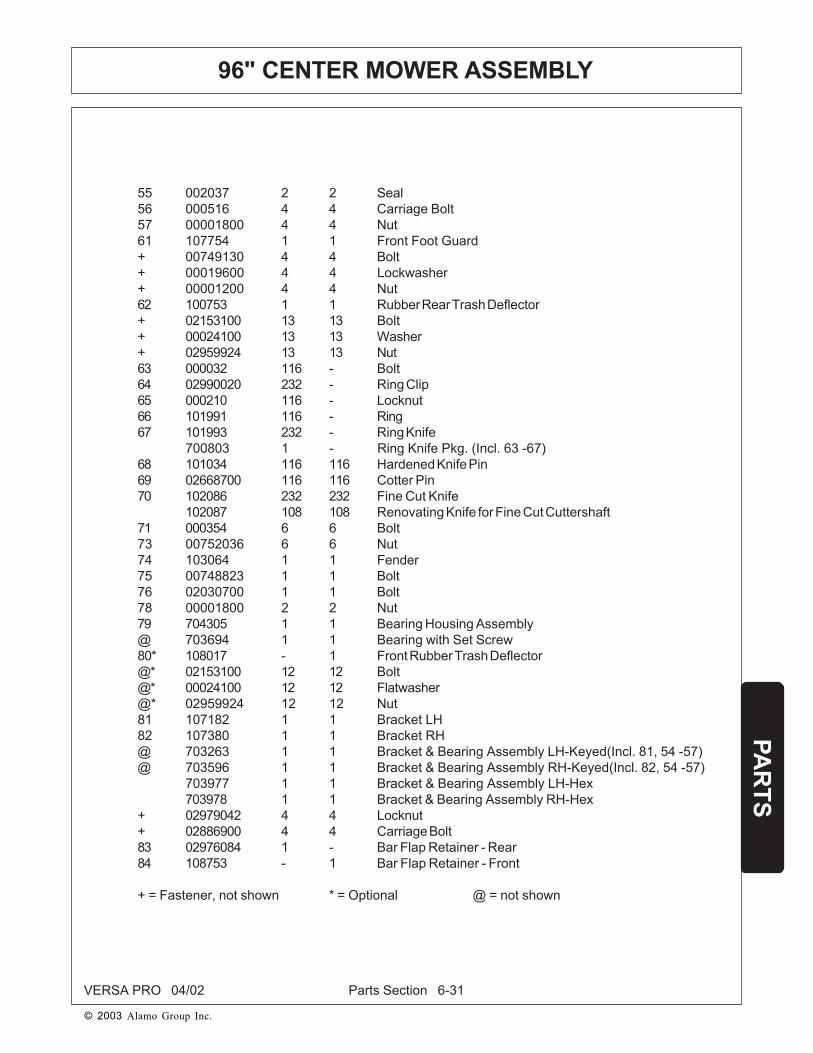
Parts Section 6-31VERSA PRO 04/02
PAR
TS
© 2003 Alamo Group Inc.
55 002037 2 2 Seal56 000516 4 4 Carriage Bolt57 00001800 4 4 Nut61 107754 1 1 Front Foot Guard+ 00749130 4 4 Bolt+ 00019600 4 4 Lockwasher+ 00001200 4 4 Nut62 100753 1 1 Rubber Rear Trash Deflector+ 02153100 13 13 Bolt+ 00024100 13 13 Washer+ 02959924 13 13 Nut63 000032 116 - Bolt64 02990020 232 - Ring Clip65 000210 116 - Locknut66 101991 116 - Ring67 101993 232 - Ring Knife
700803 1 - Ring Knife Pkg. (Incl. 63 -67)68 101034 116 116 Hardened Knife Pin69 02668700 116 116 Cotter Pin70 102086 232 232 Fine Cut Knife
102087 108 108 Renovating Knife for Fine Cut Cuttershaft71 000354 6 6 Bolt73 00752036 6 6 Nut74 103064 1 1 Fender75 00748823 1 1 Bolt76 02030700 1 1 Bolt78 00001800 2 2 Nut79 704305 1 1 Bearing Housing Assembly@ 703694 1 1 Bearing with Set Screw80* 108017 - 1 Front Rubber Trash Deflector@* 02153100 12 12 Bolt@* 00024100 12 12 Flatwasher@* 02959924 12 12 Nut81 107182 1 1 Bracket LH82 107380 1 1 Bracket RH@ 703263 1 1 Bracket & Bearing Assembly LH-Keyed(Incl. 81, 54 -57)@ 703596 1 1 Bracket & Bearing Assembly RH-Keyed(Incl. 82, 54 -57)
703977 1 1 Bracket & Bearing Assembly LH-Hex703978 1 1 Bracket & Bearing Assembly RH-Hex
+ 02979042 4 4 Locknut+ 02886900 4 4 Carriage Bolt83 02976084 1 - Bar Flap Retainer - Rear84 108753 - 1 Bar Flap Retainer - Front
+ = Fastener, not shown * = Optional @ = not shown
96" CENTER MOWER ASSEMBLY

Parts Section 6-32
© 2003 Alamo Group Inc.
VERSA PRO 03/93
REVERSE GEARBOX P/N 702673
ITEM PART NO. QTY DESCRIPTION
1 001718 1 Pinion2 001719 1 Seal3 001717 1 Nut4 001720 1 Spring Washer5 00754757 2 Bearing, Roller6 001716 1 Spacer7 00754752 2 Circlip, Internal8 001722 1 Bearing, Roller9 00753222 2 Shim10 00754761 1 Shim11 001724 1 Seal12 001725 1 Shaft w/ Crown
Wheel13 00754459 1 Bearing, Ball14 001708 8 Bolt15 001710 1 Cover16 00755633 2 Plug17 000055 2 Plug, Drain

Parts Section 6-33
© 2003 Alamo Group Inc.
VERSA PRO 03/93
MAINFRAME TO ATTACHMENT FRAME
R 6-1-93
ITEM PART NO. QTY DESCRIPTION
1 107750 1 Weldment - Mainframe2 00749130 2 Bolt3 107765 1 Weldment - Attachment Frame4 00001800 2 Nut5 107761 2 Pin6 00002700 4 Washer7 02963400 2 Pin8 01422502 2 Pin - Cotter9 107774 2 Axle Mount Bar
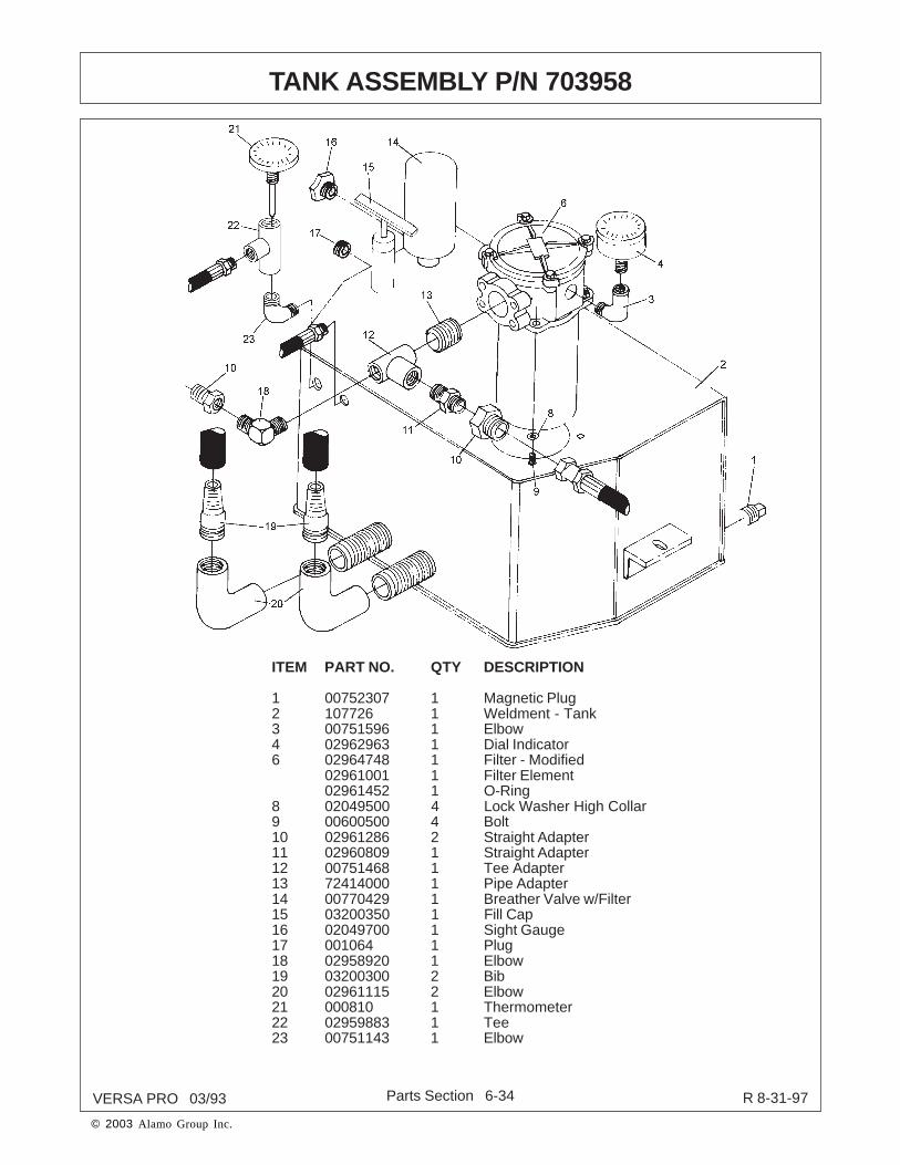
Parts Section 6-34
© 2003 Alamo Group Inc.
VERSA PRO 03/93
ITEM PART NO. QTY DESCRIPTION
1 00752307 1 Magnetic Plug2 107726 1 Weldment - Tank3 00751596 1 Elbow4 02962963 1 Dial Indicator6 02964748 1 Filter - Modified
02961001 1 Filter Element02961452 1 O-Ring
8 02049500 4 Lock Washer High Collar9 00600500 4 Bolt10 02961286 2 Straight Adapter11 02960809 1 Straight Adapter12 00751468 1 Tee Adapter13 72414000 1 Pipe Adapter14 00770429 1 Breather Valve w/Filter15 03200350 1 Fill Cap16 02049700 1 Sight Gauge17 001064 1 Plug18 02958920 1 Elbow19 03200300 2 Bib20 02961115 2 Elbow21 000810 1 Thermometer22 02959883 1 Tee23 00751143 1 Elbow
R 8-31-97
TANK ASSEMBLY P/N 703958

Parts Section 6-35
© 2003 Alamo Group Inc.
VERSA PRO 03/93
NOTE: Hydraulic Motor Assembly shown in vertical position with raised wing.
ITEM PART NO. QTY DESCRIPTION
1 001602 1 Motor2 002502 1 Solenoid Valve - Complete
002099 1 Solenoid Valve Cartridge w/Seals002098 1 Solenoid Valve Seal Kit002503 1 Solenoid Valve Coil
3 02964792 1 Manifold Block4 00286 1 Relief5 001574 1 Cap Nut6 03200283 1 Adapter7 02090900 2 Adapter 90 deg.8 63149100 1 Elbow9 001654 1 Elbow10 00011700 4 Lockwasher11 63092200 4 Bolt12 03200587 1 Plug
LEFT WING HYDRAULIC MOTOR ASSEMBLY

Parts Section 6-36
© 2003 Alamo Group Inc.
VERSA PRO 03/93
RIGHT WING HYDRAULIC MOTOR ASSEMBLY
NOTE: Hydraulic Motor Assembly shown in vertical position with raised wing.
ITEM PART NO. QTY DESCRIPTION
1 02964792 1 Manifold Block2 001602 1 Motor3 001654 1 Elbow4 002502 1 Solenoid Valve - Complete
002099 1 Solenoid Valve Cartridge w/ Seals002098 1 Solenoid Valve Seal Kit002503 1 Solenoid Valve Coil02970704 1 Solenoid Retaining Nut
5 001759 1 Valve Relief6 02957622 1 Adapter7 02958858 1 Adapter 90 deg.8 02090900 1 Adapter9 63149100 1 Elboow10 00011700 4 Lockwasher11 63092200 4 Bolt12 03200587 1 Plug (not shown)
R 7-25-97

Parts Section 6-37
© 2003 Alamo Group Inc.
VERSA PRO 03/93
HYDRAULIC MOTOR P/N 001602
ITEM PART NO. QTY DESCRIPTION
1 001641 1 Rotating Kit Assembly2 001642 1 Backplate Assembly w/Bearing3 001643 1 Keyed Driveshaft4 Non Service 1 Housing Assembly5 001644 1 Thrust Bearing & Race kit6 001645 1 Camplate Insert7* 03200409 1 O-Ring8 02766400 2 Capscrew9 03200411 1 Washer10* 03200412 1 Retaining Ring11* 03200413 2 Retaining Ring12 02966926 1 Shaft Seal Kit12A* 02966924 1 O-Ring12B* 02966922 1 Seal12C* 02966923 1 Seal Adapter13 03200521 1 Key14 03200587 1 Plug15 002339 1 Bearing, Backplate16 002340 1 Bearing, Housing
* Included in Seal Kit p/n 001648
R 07-29-97

Parts Section 6-38
© 2003 Alamo Group Inc.
VERSA PRO 03/93
CASTER WHEEL ASSEMBLY
30
R 07-21-98
33
34

Parts Section 6-39
© 2003 Alamo Group Inc.
VERSA PRO 03/93
CASTER WHEEL ASSEMBLY
ITEM PART NO. QTY DESCRIPTION
1 373024 1 Wheel Assy. (1 ea. Items 2, 3, & 373024D)
2 373024A 1 Tire
3 373024B 1 Wheel
4 373024C 1 Hub. (w/Bearing Cups & Grease Fitting)
373024D ref. Hub, (w/ Bearings, Seals, Grease Fitting, Bolts,
& Lockwasher)
5 373024G 2 Bearing Cup
6 373024F 2 Bearing Cone
7 373024E 2 Seal, Grease
8 17C1792B 1 Grease Fitting (Threaded)
00600000 1 Grease Fitting (Drive in)
9 7A8208 4 Capscrew, Hex Head
10 7A6166 4 Capscrew, Hex Head
11 13800 4 Lockwasher
12 13600 4 Lockwasher
13 5B6160 4 Nut
14 0585020210 1 Fork (Weldment)
15 37302C2C 2 Sleeve, Shoulder
16 37302D2B 2 Dust Cap
17 511016 2 Bushing, Spacer
18 37302D2A 1 Bolt, Spindle (Special)
19 15B1200 1 Washer, Plain SAE
20 15B2400 2 Washer, Plain SAE
21 5E12160 1 Nut. Slotted
22 1621/2012 1 Pin, Cotter
23 00758829 1 Roll Pin
24 373024H 1 Tire & Wheel (Bolted Assy. Only, Less Hub)
25 107734 1 Weldment - Caster Arm (LH)
107733 1 Weldment - Caster Arm (RH)
26 107816 4 Spacer
27 00768823 2 Bolt
28 00001800 6 LockNut
29 00002700 4 Flatwasher
30 642013 2 Spacer
31 02027400 4 Bolt
32 00749130 4 Bolt
33 361129 2 Bushing (Inserted Inside Tube)
34 00752670 1 Grease Fitting
Item 1-24 make Assembly P/N 0585020200
R 10-06-04

Parts Section 6-40
© 2003 Alamo Group Inc.
VERSA PRO 03/93
HYDRAULIC SCHEMATIC
ITEM PART NO. QTY DESCRIPTION
1 002477 1 Hose2 02839000 2 Hose3 02964451 1 Hose4 02961321 1 Hose5 02965364 1 Hose6 002476 2 Hose7 001859 2 Hose8 002478 1 Hose9 002480 1 Hose10 002479 1 Hose11 001579 2 Hose12 002628 2 Hose13 002462 2 Adapter - 90 deg.14 001921 2 Adapter - 90 deg.15 02957622 2 Adapter - Straight16 02043600 2 Adapter - 45 deg.17 02958858 1 Adapter - 90 deg.
R 8-26-99

Parts Section 6-41
© 2003 Alamo Group Inc.
VERSA PRO 03/93
CABLE MOUNT PLATE
ITEM PART NO. QTY DESCRIPTION
1 108005 1 Weldment-Cable Mount2 108015 2 Knob3 02962879 2 Cable4 10058000 2 Bolt5 02959924 2 Nut
1
3 4
5
22

Parts Section 6-42VERSA PRO 06/01
PAR
TS
© 2003 Alamo Group Inc.
OPTIONAL EQUIPMENT, AND PACKAGES
CASTER WHEEL PACKAGE
702321 Knife Grinder (Sharpens all ALAMO flail mower knives)700413 Knife Straightener Set (Two 102092 slotted bars)107176 & 001967 62"Rubber Covered Roller107177 & 001968 74" Rubber Covered Roller107178 & 001969 88" Rubber Covered Roller703262 & 001967 62" Rubber Covered Roller Assembly703261 & 001968 74" Rubber Covered Roller Assembly703260 & 001969 88" Rubber Covered Roller Assembly703602 62" Roller Scraper Kit703603 74" Roller Scraper Kit703604 88" Roller Scraper Kit700500 Pneumatic Caster Wheel Pkg., 180 deg. Swivel, Field Installed700502 Laminated Caster Wheel Pkg., 180 deg. Swivel, Field Installed701056 Pneumatic Caster Wheel Pkg., 360 deg. Swivel, Field Installed701057 Laminated Caster Wheel Pkg., 360 deg. Swivel, Field Installed704036 Rear Roller Scraper107787 & 002452 Rubber Covered Roller
(All above Caster Wheel Pkg’s include fasteners)

Parts Section 6-43VERSA PRO 06/01
PAR
TS
© 2003 Alamo Group Inc.
OPTIONAL EQUIPMENT, AND PACKAGES
ITEM PART NO. QTY DESCRIPTION
1* 100752 2 Right Caster Bracket
2* 100753 2 Left Caster Bracket
3 701058 2 360 Deg. Caster Socket
Assembly w/Grease Fitting
4 700191 2 180 Deg. Caster Socket
Assembly w/Grease Fitting
000142 4 Bolt
000520 4 Lockwasher
000170 4 Nut
5 000554 2 Bolt
6 000520 2 Lockwasher
7 103767 2 Washer
8 100141 2 Caster Half Fork
9 000621 2 Hub w/Bearing Cups
10 000226 4 Bearing Cups
11 000622 8 Hub Bolt w/item 19
000554 8 Hub Bolt
000520 8 Lockwasher
12 000573 2 Spacer
13 000201 2 Seal
14 000225 4 Bearing Cone
15 101780 2 Washer
16 000122 2 Nut
17 000123 2 Cotter Pin
18 000247 2 Hub Cap
000620 2 Hub Complete (incl. 9, 12-14, 18)
702272 2 Lower Fork Assembly (Incl. 8, 9, 12-18)
19 000619 2 Wheel (tube type tire)
20 000623 2 Tube
21 000618 2 Tire (tube type)
000617 2 Wheel, Tire and Tube Assembly
(incl. 19-21)
22** 700280 2 Laminated Tire/Wheel Assembly
* For field installation, brackets are shipped loose. They are to be welded to the
housing by the customer. Brackets for mowers ordered with brackets are welded
at the factory.
** Optional

LIMITED WARRANTY
1. LIMITED WARRANTIES1.01.Alamo Industrial warrants for one year from the purchase date to the original non-commercial, governmental, or
municipal purchaser (“Purchaser”) and warrants for six months to the original commercial or industrial purchaser(“Purchaser”) that the goods purchased are free from defects in material or workmanship.
1.02.Manufacturer will replace for the Purchaser any part or parts found, upon examination at one of its factories, to bedefective under normal use and service due to defects in material or workmanship.
1.03.This limited warranty does not apply to any part of the goods which has been subjected to improper or abnormal use,negligence, alteration, modification, or accident, damaged due to lack of maintenance or use of wrong fuel, oil, orlubricants, or which has served its normal life. This limited warranty does not apply to any part of any internalcombustion engine, or expendable items such as blades, shields, guards, or pneumatic tires except as specifically foundin your Operator’s Manual.
1.04.Except as provided herein, no employee, agent, Dealer, or other person is authorized to give any warranties of anynature on behalf of Manufacturer.
2. REMEDIES AND PROCEDURES.2.01.This limited warranty is not effective unless the Purchaser returns the Registration and Warranty Form to Manufacturer
within 30 days of purchase.2.02.Purchaser claims must be made in writing to the Authorized Dealer (“Dealer”) from whom Purchaser purchased the
goods or an approved Authorized Dealer (“Dealer”) within 30 days after Purchaser learns of the facts on which theclaim is based.
2.03.Purchaser is responsible for returning the goods in question to the Dealer.2.04.If after examining the goods and/or parts in question, Manufacturer finds them to be defective under normal use and
service due to defects in material or workmanship, Manufacturer will:(a) Repair or replace the defective goods or part(s) or(b) Reimburse Purchaser for the cost of the part(s) and reasonable labor charges (as determined by Manufacturer)
if Purchaser paid for the repair and/or replacement prior to the final determination of applicability of the warrantyby Manufacturer.
The choice of remedy shall belong to Manufacturer.2.05.Purchaser is responsible for any labor charges exceeding a reasonable amount as determined by Manufacturer and
for returning the goods to the Dealer, whether or not the claim is approved. Purchaser is responsible for the trans-portation cost for the goods or part(s) from the Dealer to the designated factory.
3. LIMITATION OF LIABILITY.3.01.MANUFACTURER DISCLAIMS ANY EXPRESS (EXCEPT AS SET FORTH HEREIN) AND IMPLIED WARRANTIESWITH RESPECT TO THE GOODS INCLUDING, BUT NOT LIMITED TO, MERCHANTABILITY AND FITNESSFOR A PARTICULAR PURPOSE.3.02.MANUFACTURER MAKES NO WARRANTY AS TO THE DESIGN, CAPABILITY, CAPACITY, OR SUITABILITY FOR
USE OF THE GOODS.3.03.EXCEPT AS PROVIDED HEREIN, MANUFACTURER SHALL HAVE NO LIABILITY OR RESPONSIBILITY TO
PURCHASER OR ANY OTHER PERSON OR ENTITY WITH RESPECT TO ANY LIABILITY, LOSS, OR DAMAGECAUSED OR ALLEGED TO BE CAUSED DIRECTLY OR INDIRECTLY BY THE GOODS INCLUDING, BUT NOTLIMITED TO, ANY INDIRECT, SPECIAL, CONSEQUENTIAL, OR INCIDENTAL DAMAGES RESULTING FROM
THE USE OR OPERATION OF THE GOODS OR ANY BREACH OF THIS WARRANTY. NOT WITHSTANDING THEABOVE LIMITATIONS AND WARRANTIES, MANUFACTURER’S LIABILITY HEREUNDER FOR DAMAGESINCURRED BY PURCHASER OR OTHERS SHALL NOT EXCEED THE PRICE OF THE GOODS.3.04.NO ACTION ARISING OUT OF ANY CLAIMED BREACH OF THIS WARRANTY OR TRANSACTIONS UNDERTHIS WARRANTY MAY BE BROUGHT MORE THAN TWO (2) YEARS AFTER THE CAUSE OF ACTION HAS
OCCURRED.4. MISCELLANEOUS.
4.01.Proper Venue for any lawsuits arising from or related to this limited warranty shall be only in Guadalupe County,Texas.
4.02.Manufacturer may waive compliance with any of the terms of this limited warranty, but no waiver of any terms shallbe deemed to be a waiver of any other term.
4.03.If any provision of this limited warranty shall violate any applicable law and is held to be unenforceable, then theinvalidity of such provision shall not invalidate any other provisions herein.
4.04.Applicable law may provide rights and benefits to purchaser in addition to those provided herein.
KEEP FOR YOUR RECORDS
ATTENTION: Purchaser should fill in the blanks below for his reference when buying repair parts and/or for proper machineidentification when applying for warranty.
Alamo Industrial Implement Model ____________________________ Serial Number ________________________________
Date Purchased __________________________________________ Dealer ______________________________________
ATTENTION:READ YOUR OPERATOR'S MANUAL
ALAMO INDUSTRIAL
ALAMO INDUSTRIALAn Alamo Group Company
1502 E. WalnutSeguin, Texas 78155
830-379-1480

TO THE OWNER/OPERATOR/DEALER
Keep children away from danger all day,every day...
Equip tractors with rollover protection (ROPS)and keep all machinery guards in place...
Please work, drive, play and live each day withcare and concern for your safety and that ofyour family and fellow citizens.
To keep your implement running efficiently and safely, read your manual thoroughly and follow these directions and theSafety Messages in this Manual. The Table of Contents clearly identifies each section where you can easily find theinformation you need.
The OCCUPATIONAL SAFETY AND HEALTH ACT (1928.51 Subpart C) makes these minimum safety requirementsof tractor operators:
REQUIRED OF THE OWNER:
1. Provide a Roll-Over-Protective Structure that meets the requirements of this Standard; and2. Provide Seatbelts that meet the requirements of this paragraph of this Standard and SAE J4C; and3. Ensure that each employee uses such Seatbelt while the tractor is moving; and4. Ensure that each employee tightens the Seatbelt sufficiently to confine the employee to the protected area
provided by the ROPS.
REQUIRED OF THE OPERATOR
1. Securely fasten seatbelt if the tractor has a ROPS.2. Where possible, avoid operating the tractor near ditches, embankments, and holes.3. Reduce speed when turning, crossing slopes, and on rough, slick, or muddy surfaces.4. Stay off slopes too steep for safe operation.5. Watch where you are going - especially at row ends, on roads, and around trees.6. Do not permit others to ride.7. Operate the tractor smoothly - no jerky turns, starts, or stops.8. Hitch only to the drawbar and hitch points recommended by the tractor manufacturer.9. When the tractor is stopped, set brakes securely and use park lock, if available.

VERSA PRO-OMWPL - 04/03Printed U.S.A.
P/N 803350