motox - industry - industry - siemens · ba 2320 la / lg and lai / lgi motors for fitting to motox...
TRANSCRIPT

Answers for industry.
MOTOX
LA / LG Motors
BA 2320
Operating Instructions· 05/2010


�BA 2320�
___________________
___________________
___________________
___________________
___________________
___________________
___________________
___________________
___________________
___________________
___________________
___________________
MOTOX
LA / LG Motors BA 2320
Operating Instructions
Motors for mounting on MOTOX and CAVEX gearboxes
05/2010
General information and safety notes 1
Technical description
2
Incoming goods, transport, and storage
3
Mounting
4
Commissioning
5
Operation
6
Faults, causes and remedies
7
Service and maintenance
8
Disposal
9
Technical data
10
Spare parts / Accessories
11
EC Declaration of Conformity
12

Legal information
Legal information Warning notice system
This manual contains notices you have to observe in order to ensure your personal safety, as well as to prevent damage to property. The notices referring to your personal safety are highlighted in the manual by a safety alert symbol, notices referring only to property damage have no safety alert symbol. These notices shown below are graded according to the degree of danger.
DANGER indicates that death or severe personal injury will result if proper precautions are not taken.
WARNING indicates that death or severe personal injury may result if proper precautions are not taken.
CAUTION with a safety alert symbol, indicates that minor personal injury can result if proper precautions are not taken.
CAUTION without a safety alert symbol, indicates that property damage can result if proper precautions are not taken.
NOTICE indicates that an unintended result or situation can occur if the corresponding information is not taken into account.
If more than one degree of danger is present, the warning notice representing the highest degree of danger will be used. A notice warning of injury to persons with a safety alert symbol may also include a warning relating to property damage.
Qualified Personnel The product/system described in this documentation may be operated only by personnel qualified for the specific task in accordance with the relevant documentation for the specific task, in particular its warning notices and safety instructions. Qualified personnel are those who, based on their training and experience, are capable of identifying risks and avoiding potential hazards when working with these products/systems.
Proper use of Siemens products Note the following:
WARNING Siemens products may only be used for the applications described in the catalog and in the relevant technical documentation. If products and components from other manufacturers are used, these must be recommended or approved by Siemens. Proper transport, storage, installation, assembly, commissioning, operation and maintenance are required to ensure that the products operate safely and without any problems. The permissible ambient conditions must be adhered to. The information in the relevant documentation must be observed.
Trademarks All names identified by ® are registered trademarks of the Siemens AG. The remaining trademarks in this publication may be trademarks whose use by third parties for their own purposes could violate the rights of the owner.
Disclaimer of Liability We have reviewed the contents of this publication to ensure consistency with the hardware and software described. Since variance cannot be precluded entirely, we cannot guarantee full consistency. However, the information in this publication is reviewed regularly and any necessary corrections are included in subsequent editions.
Siemens AG Industry Sector Postfach 48 48 90026 NÜRNBERG GERMANY
Ⓟ 10/2010
Copyright © Siemens AG 2010. Technical data subject to change

BA 2320 Operating Instructions, 05/2010 5
Table of contents
1 General information and safety notes ........................................................................................................ 7
1.1 General information .......................................................................................................................7 1.2 Intended use ..................................................................................................................................9 1.3 General safety notes....................................................................................................................10
2 Technical description ............................................................................................................................... 11 2.1 General description......................................................................................................................11 2.2 Housing ........................................................................................................................................11 2.3 Cooling .........................................................................................................................................12 2.4 Terminal box ................................................................................................................................12 2.5 Rating plate ..................................................................................................................................12 2.6 Surface treatment ........................................................................................................................13 2.6.1 General information on surface treatment ...................................................................................13 2.6.2 Painted version ............................................................................................................................13 2.6.3 Primed version .............................................................................................................................15
3 Incoming goods, transport, and storage................................................................................................... 17 3.1 Incoming goods............................................................................................................................17 3.2 Transport......................................................................................................................................18 3.2.1 General information on transport .................................................................................................18 3.2.2 Fastening for suspended transport ..............................................................................................19 3.3 Storage.........................................................................................................................................21 3.3.1 General information for storage ...................................................................................................21 3.3.2 Storage up to 6 months................................................................................................................21 3.3.3 Storage up to 36 months with long-term preservation (optional).................................................22
4 Mounting.................................................................................................................................................. 23 4.1 Unpacking ....................................................................................................................................23 4.2 General information on installation ..............................................................................................23 4.3 Tightening torque for fastening bolts on the motor ......................................................................25 4.4 Installation conditions for the motor .............................................................................................26 4.5 Condensation drain holes (optional) ............................................................................................26 4.6 Mounting the input or output element on the motor shaft ............................................................27 4.7 Connecting the motor...................................................................................................................28 4.7.1 General information on motor connection....................................................................................28 4.7.2 Terminal box ................................................................................................................................29 4.7.3 Terminal designations..................................................................................................................30 4.7.4 Direction of rotation......................................................................................................................30 4.7.5 Connecting the cables in the terminal box...................................................................................31 4.7.6 Assembly and laying of cables.....................................................................................................32

Table of contents
BA 2320 6 Operating Instructions, 05/2010
4.7.7 Tightening torque for bolts in electrical connections................................................................... 32 4.7.8 Forced ventilation (optional)........................................................................................................ 33 4.7.8.1 General information for commissioning of forced ventilation ...................................................... 33 4.7.8.2 Circuit diagrams for forced ventilation......................................................................................... 33 4.7.8.3 Technical data for forced ventilation ........................................................................................... 34 4.7.9 Operation on the converter ......................................................................................................... 36
5 Commissioning ........................................................................................................................................ 37 5.1 Checking the insulation resistance ............................................................................................. 37 5.2 Commissioning the motor ........................................................................................................... 39
6 Operation................................................................................................................................................. 41 7 Faults, causes and remedies ................................................................................................................... 43 8 Service and maintenance ........................................................................................................................ 45
8.1 General notes about maintenance.............................................................................................. 45 8.2 Description of maintenance and repair work............................................................................... 46 8.2.1 Locking the manual release of the brake (optional).................................................................... 46 8.2.2 Lubrication................................................................................................................................... 46 8.2.3 Cleaning the motor...................................................................................................................... 48 8.2.4 Checking tightness of fastening bolts ......................................................................................... 48 8.2.5 Inspection of the motor................................................................................................................ 49 8.2.6 Servicing the brake ..................................................................................................................... 49 8.2.6.1 Wear of the spring-operated brake ............................................................................................. 49 8.2.6.2 Maintenance intervals for the brake............................................................................................ 50 8.2.6.3 Adjusting the air gap ................................................................................................................... 51 8.2.6.4 Replacing the friction lining ......................................................................................................... 53
9 Disposal................................................................................................................................................... 55 10 Technical data ......................................................................................................................................... 57
10.1 Type designation......................................................................................................................... 57 10.2 General technical data ................................................................................................................ 58 10.3 Weight ......................................................................................................................................... 59
11 Spare parts / Accessories ........................................................................................................................ 61 11.1 Stocking of spare parts ............................................................................................................... 61 11.2 Spare parts lists .......................................................................................................................... 62 11.2.1 MODULOG motor sizes 71 - 200................................................................................................ 62 11.2.2 MODULOG brake motor sizes LA71 - LA160............................................................................. 65 11.2.3 MODULOG brake motor sizes LA71 - LA160 with backstop ...................................................... 69 11.2.4 Encoder ....................................................................................................................................... 73 11.2.4.1 Encoder on fan cover .................................................................................................................. 73 11.2.4.2 Encoder in motor with forced ventilation ..................................................................................... 74
12 EC Declaration of Conformity .................................................................................................................. 75

BA 2320 Operating Instructions, 05/2010 7
General information and safety notes 11.1 General information
CAUTION Siemens does not accept liability for any damage or outages resulting from non-compliance with these operating instructions.
These operating instructions are an integral part of the motor supplied and must be kept in its vicinity for reference at all times. These operating instructions apply to the standard version of the motors for mounting on the MOTOX and CAVEX gearbox series: ● MODULOG motors sizes 71 to 200 ● Motor sizes 225 to 315
Table 1- 1 Order number code
Structure of the order number - Position Motor 1 2 3 4 11 12
Motor LA / LG or LAI / LGI 2 K J 1 1 3
Note In addition to these operating instructions, special contractual agreements and technical documentation apply to these special motor designs and the associated supplementary equipment. Please refer to the other operating instructions supplied with the product.
The motors described here correspond to the state of the art at the time these operating instructions were printed. In the interest of technical progress we reserve the right to make changes to the individual assemblies and accessories which we regard as necessary to preserve their essential characteristics and improve their efficiency and safety.

General information and safety notes 1.1 General information
BA 2320 8 Operating Instructions, 05/2010
If you have any technical questions, please contact Technical Support. Europe - Germany Phone: +49 (0) 911 895 7222 Fax: +49 (0) 911 895 7223 America - USA Phone: +1 42 32 62 25 22 Asia - China Phone: +86 10 64 75 75 75 Email: [email protected] Internet German: http://www.siemens.de/automation/support-request Internet English: http://www.siemens.com/automation/support-request
Applicable operating instructions
Table 1- 2 MOTOX gearbox operating instructions
Title Product BA 2010 MOTOX gearboxes BA 2011 MOTOX helical worm gearboxes and geared motors BA 2019 MOTOX input units BA 2510 MOTOX optional add-on units BA 2515 MOTOX gearboxes for overhead conveyors
Table 1- 3 Motor operating instructions
Title Product BA 2310 Three-phase and single-phase alternating current motors and brake motors with
accessories BA 2320 LA / LG and LAI / LGI motors for fitting to MOTOX and CAVEX gearboxes
Table 1- 4 CAVEX gearbox operating instructions
Title Product BA 6610TU CAVEX worm gearboxes, type C.., size 63 to 630 BA 6611TU CAVEX worm gearboxes, type CS.., size 63 to 630 BA 6612TU CAVEX worm gearboxes, type CD.., size 100 to 630 BA 6800TU CAVEX elevator drives, type CG 26, size 100, 112, 135, 170 BA 6801TU CAVEX elevator drives, type CG 45, size 120 BA 6802TU CAVEX escalator drives, type CG 26, size 100, 112, 135, 170

General information and safety notes 1.2 Intended use
BA 2320 Operating Instructions, 05/2010 9
1.2 Intended use The motors described in these operating instructions have been designed for stationary use in general engineering applications. They comply with the harmonized standards of the series EN 60034 (VDE 0530). They are not approved for operation in hazardous zones and areas. Unless otherwise agreed, the motors have been designed for use in plants and equipment in industrial environments. The motors have been built using state-of-the-art technology and are shipped in an operationally reliable condition. Changes made by users could affect this operational reliability and are forbidden.
Note The performance data assumes an ambient temperature of -15 °C to +40 °C and an installation altitude of up to 1,000 m above sea level. In the case of other ambient temperatures and installation altitudes, please contact Technical Support.
The motors have been designed solely for the application described in Technical data (Page 57). Do not operate the motors outside the specified power limits. Other operating conditions must be contractually agreed. Equipment with degree of protection ≤ IP54 must never be used outdoors. Air-cooled versions are designed for ambient temperatures of -15 °C to +40 °C and for an installation altitude of up to 1,000 m above sea level. Please note any deviations to the data on the rating plate. Conditions at the location of use must comply with all specifications on the rating plate. Do not stand or walk on the geared motors.

General information and safety notes 1.3 General safety notes
BA 2320 10 Operating Instructions, 05/2010
1.3 General safety notes Shut down the geared motors and disconnect the power before you carry out any work on them. Make sure that the drive unit cannot be turned on accidentally, e.g. lock the key-operated switch or remove the fuses in the power supply. Place a warning notice at the drive connection point which clearly indicates that work is in progress on the geared motor. Carry out all work with great care and with due regard to safety. Read the instructions on the rating plates attached to the geared motor. The rating plates must be kept free from paint and dirt at all times. Replace any missing rating plates. Ensure compliance with the relevant safety and environmental regulations during transport, mounting and dismantling, operation, and care and maintenance of the unit. Take appropriate protective measures to prevent accidental contact with rotating drive parts, such as couplings, gear wheels or belt drives. Take appropriate measures to prevent accidental contact with parts and equipment that heat up to over +70 °C during operation. Ensure adequate ventilation when working with solvents. Do not inhale vapors. Do not smoke. Collect and dispose of used oil in accordance with regulations. Remove oil spillages immediately with an oil-binding agent in compliance with environmental requirements. If the geared motor is being installed in a plant or equipment, the manufacturers of such plant or equipment must ensure that the contents of these operating instructions are incorporated into their own instructions, information, and descriptions.
BA 2320 Operating Instructions, 05/2010 11
Technical description 22.1 General description
The motor complies with the following regulations:
Table 2- 1 Overview of standards for the motor
Designation Standard Ratings and operating performance EN 60034-1 Degree of protection EN 60034-5 Cooling EN 60034-6 Type of construction according to modular system EN 60034-7 Terminal marking and direction of rotation EN 60034-8 Noise emission EN 60034-9 Thermal protection EN 60034-11 Starting characteristics for rotating electrical motors EN 60034-12 Vibration severity levels EN 60034-14 IEC standard voltages IEC 60038 Safety of machinery EN 60204-1
The motor is equipped with grease-lubricated roller bearings. The bearings are permanently lubricated. The stator winding is designed for temperature class 155(F). In the standard version, the rotor corresponds to vibration severity level A. The technical data for the optional monitoring equipment can be viewed in the circuit diagrams, on the rating plate or in the special order documents.
2.2 Housing The stator frame and the rating plate are made from aluminum casting up to size 160, and from cast iron from size 180. The surface of the stator frame is equipped with cooling fins and a mounted terminal box. The fan cover is made of sheet steel.
Technical description 2.3 Cooling
BA 2320 12 Operating Instructions, 05/2010
2.3 Cooling
CAUTION Dust deposits prevent heat radiation and cause high housing temperatures. Keep the motor free from dirt and dust, etc.
The motors are designed for fin cooling; an external fan draws the cooling air in through the opening in the fan cover and blows it across the surface of the stator frame.
2.4 Terminal box In the motor terminal box, alongside the motor connection terminals (terminal board), additional connecting clamps are available for monitoring equipment. The number of available terminals is shown in the circuit diagrams. The circuit diagrams are located in the terminal box.
2.5 Rating plate The rating plate on the gearbox or geared motor is of coated aluminum foil. It is covered with a special masking film which ensures permanent resistance to UV radiation and media of all kinds, such as oils, greases, salt water and cleaning agents. The adhesive and the material ensure firm adhesion and long-term legibility within the operating temperature range from -40 °C to +155 °C. The edges of the rating plate are paint-finished to match the color of the gearbox or motor to which it is affixed. In special cases, riveted or bolted metal plates are used.
Technical description 2.6 Surface treatment
BA 2320 Operating Instructions, 05/2010 13
2.6 Surface treatment
2.6.1 General information on surface treatment All paint finishes are sprayed on.
CAUTION Any damage to the paint finish will destroy the exterior protection and cause corrosion. Do not damage the paint.
Note Information about repainting does not guarantee the quality of the paint product purchased from your supplier. Only the paint manufacturer is liable for quality and compatibility.
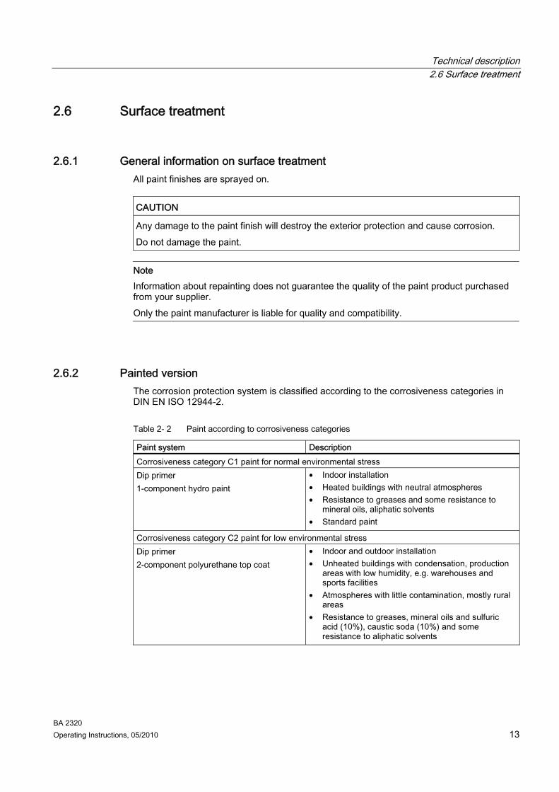
2.6.2 Painted version The corrosion protection system is classified according to the corrosiveness categories in DIN EN ISO 12944-2.
Table 2- 2 Paint according to corrosiveness categories
Paint system Description Corrosiveness category C1 paint for normal environmental stress Dip primer 1-component hydro paint
• Indoor installation • Heated buildings with neutral atmospheres • Resistance to greases and some resistance to
mineral oils, aliphatic solvents • Standard paint
Corrosiveness category C2 paint for low environmental stress Dip primer 2-component polyurethane top coat
• Indoor and outdoor installation • Unheated buildings with condensation, production
areas with low humidity, e.g. warehouses and sports facilities
• Atmospheres with little contamination, mostly rural areas
• Resistance to greases, mineral oils and sulfuric acid (10%), caustic soda (10%) and some resistance to aliphatic solvents

Technical description 2.6 Surface treatment
BA 2320 14 Operating Instructions, 05/2010
Paint system Description Corrosiveness category C3 paint for medium environmental stress Dip primer 2-component polyurethane base coat 2-component polyurethane top coat
• Indoor and outdoor installation • Production areas with high humidity and some air
contamination, e.g. food production areas, dairies, breweries and laundries
• Urban and industrial atmospheres, moderate contamination from sulfur dioxide, coastal areas with low salt levels
• Resistance to greases, mineral oils, aliphatic solvents, sulfuric acid (10%), caustic soda (10%)
Corrosiveness category C4 paint for high environmental stress Dip primer 2-component epoxy zinc phosphate 2-component polyurethane top coat
• Indoor and outdoor installation • Chemical plants, swimming pools, wastewater
treatment plants, electroplating shops, and boathouses above seawater
• Industrial areas and coastal areas with moderate salt levels
• Resistance to greases, mineral oils, aliphatic solvents, sulfuric acid (10%), caustic soda (10%)
Corrosiveness category C5 paint for very high environmental stress Dip primer 2-component epoxy zinc phosphate 2-component epoxy iron mica 2-component polyurethane top coat
• Indoor and outdoor installation • Buildings and areas with almost constant
condensation and high contamination, e.g. malt factories and aseptic areas
• Industrial areas with high humidity and aggressive atmosphere, coastal areas and offshore environments with high salt levels
• Resistance to greases, mineral oils, aliphatic solvents, sulfuric acid (10%), caustic soda (10%)
In case of corrosiveness category C1, can be overpainted with 1-component hydrosystem after prior rubbing down. In case of corrosiveness category C2 to C5, can be overpainted with 2-component polyurethane paint, 2-component epoxide paint, and 2-component acrylic paint after prior rubbing down.

Technical description 2.6 Surface treatment
BA 2320 Operating Instructions, 05/2010 15
2.6.3 Primed version
Table 2- 3 Primer according to corrosiveness categories
Paint system Can be overpainted with Unpainted (corrosiveness category C1 G) Cast iron parts immersion primed, steel parts primed or zinc-plated, aluminum and plastic parts untreated
Plastic paint, synthetic resin paint, oil paint, 2-component polyurethane paint, 2-component epoxide paint
Primed according to corrosiveness category C2 G 2-component metal primer, desired coat thickness 60 μm
2-component polyurethane paint, 2-component epoxide paint and acid-hardening paint, 2-component acrylic paint
Primed according to corrosiveness category C4 G 2-component epoxide zinc phosphate, desired coat thickness 120 μm
2-component polyurethane paint, 2-component epoxide paint and acid-hardening paint, 2-component acrylic paint
On gearbox or geared motor versions which are primed or unpainted the rating plate and the masking film are covered with a paint-protective film. These facilitate repainting without further preparation, e.g., masking with adhesive tape.
Peeling off the paint-protective film The paint coat must have fully hardened before the paint-protective film is peeled off (be at least "touch-proof").
① Company logo ② Masking film ③ Rating plate ④ Paint-protective film ⑤ Peeling tab
Figure 2-1 Rating plate with paint-protective film
Procedure 1. Pull the peeling tab ⑤ up.
2. Carefully peel the paint-protective film ④ off diagonally from one corner (not parallel to the plate).
3. Blow any paint fragments away or wipe them off with a clean cloth. You have now removed the paint-protective film.

Technical description 2.6 Surface treatment
BA 2320 16 Operating Instructions, 05/2010
BA 2320 Operating Instructions, 05/2010 17
Incoming goods, transport, and storage 33.1 Incoming goods
CAUTION Make sure that damaged gearboxes or geared motors are not put into operation.
Note Do not open or damage parts of the packaging that preserve the product.
Note Check that the technical specifications are in accordance with the purchase order. Inspect the delivery immediately on arrival for completeness and any transport damage. Notify the freight company of any damage caused during transport immediately (this is the only way to have damage rectified free of charge). Siemens Geared Motors GmbH will not accept any claims relating to items missing from the delivery and which are submitted at a later date.
The gearbox or geared motor is delivered in a fully assembled condition. Additional items may be delivered packaged separately. The products supplied are listed in the dispatch papers.

Incoming goods, transport, and storage 3.2 Transport
BA 2320 18 Operating Instructions, 05/2010
3.2 Transport
3.2.1 General information on transport
CAUTION The use of force will damage the gearbox or geared motor. Transport the gearbox or geared motor carefully. Avoid knocks. Before putting the drive into operation, remove any transport fixtures and keep them safe or render them ineffective. For further transports reuse or reactivate them again.
Different forms of packaging may be used, depending on the size of the gearbox or geared motor and the method of transport. Notwithstanding contractual agreements to the contrary, the packaging complies with HPE Packaging Guidelines (Bundesverband Holzpackmittel Paletten Exportverpackungen e.V., the German Federal Association for wooden packaging means, pallets, and export packaging). Note the symbols which appear on the packing. These have the following meanings:
This way up Center of gravity
Fragile
Do not use hand hook
Keep dry
Attach here
Keep cool

Incoming goods, transport, and storage 3.2 Transport
BA 2320 Operating Instructions, 05/2010 19
3.2.2 Fastening for suspended transport
DANGER Gearboxes or geared motors may come loose and fall down during transport if not secured sufficiently.
Observe the maximum load for the transport eye ③ of the bevel helical gearbox or the eyebolt axis ④.
Use only the transport eye ③ or eyebolt ④ of the gearbox to transport the gearbox or geared motor.
Do not use the integrally cast lifting eyes ① on the motor for transport because of the risk of breaking. Only use the eyebolt ② on the motor to transport the motor prior to mounting or following removal. If necessary, use additional, suitable lifting accessories for transport or on installation. When attaching by a number of chains and ropes just two strands must be sufficient to bear the entire load. Secure lifting accessories against slipping.
CAUTION Do not rig eyebolts to the front threads at the shaft ends for transportation purposes.
Transport eye on the bevel helical gearbox Eyebolt on the helical gearbox, parallel shaft
gearbox, helical worm gearbox
① Integrally cast eye on the motor ② Eyebolt on the motor ③ Transport eye on the bevel helical gearbox ④ Eyebolt on the gearbox Figure 3-1 Fastening the gearbox or geared motor for suspended transport

Incoming goods, transport, and storage 3.2 Transport
BA 2320 20 Operating Instructions, 05/2010
The maximum load m in kg generated by the geared motor to be attached, with pull ↑ in direction F is listed in the following tables:
Table 3- 1 Maximum load of the transport eye on the bevel helical gearbox
m d2 m d2 Size [kg] [mm]
Size [kg] [mm]
K.38 200 22 K.128 800 40 K.48 250 22 K.148 1,300 44 K.68 350 26 K.168 1,800 55 K.88 600 30 K.188 2,300 55 K.108 750 35
Table 3- 2 Maximum load of the eyebolt on the gearbox
m d3 m d3 Thread size [kg] [mm]
Thread size [kg] [mm]
M8 140 36 M20 1,200 72 M10 230 45 M24 1,800 90 M12 340 54 M30 3,600 108 M16 700 63
Procedure 1. Mount the geared motor on the transport device by the heaviest permissible weight to be
attached. This will normally be on the main gearbox. 2. Check that the eyebolt is firmly seated. The geared motor is slung for transport.

Incoming goods, transport, and storage 3.3 Storage
BA 2320 Operating Instructions, 05/2010 21
3.3 Storage
3.3.1 General information for storage
DANGER Do not stack gearboxes or geared motors one on top of another.
CAUTION Mechanical damage (scratches), chemical damage (acids, alkalis) and thermal damage (sparks, welding beads, heat) cause corrosion which may render the external protective coating ineffective. Do not damage the paint.
Note Notwithstanding contractual agreements to the contrary, the guarantee period for the standard preservative lasts 6 months from the date of delivery. In the case of storage in transit over 6 months, special arrangements must be made for preservation. Please contact Technical Support.
3.3.2 Storage up to 6 months The gearbox or geared motor must be covered and stored in its position of use on a horizontal wooden support in a dry place not subject to significant temperature fluctuations. The storage location must be vibration- and shock-free. The free shaft ends and flange surface are painted for protection.

Incoming goods, transport, and storage 3.3 Storage
BA 2320 22 Operating Instructions, 05/2010
3.3.3 Storage up to 36 months with long-term preservation (optional)
CAUTION The gearbox is completely filled with operating oil and closed airtight with a plug or by pressure venting with transport fixture. Check the oil level before commissioning.
Store the gearbox or geared motor in dry, dust-free, and temperate locations. Special packing is then not necessary. Otherwise, the gearbox or geared motor must be packed in plastic film or packed in airtight sealed film and water absorbing agents. Cover them to provide protection against sun and rain. The storage location must be vibration- and shock-free. The free shaft ends, sealing elements and flanges must be coated with a protective layer of grease. The life of the corrosion protection is 36 months from delivery. Do not reduce the oil level during short-time startup for 10 minutes in no-load operation. Carry out the following precautionary measures after every period of 6 months in storage:
Table 3- 3 Preventive action
Storage period in months Action 6 12 18 24 30 36
Checking the insulation resistance - - x x x x Short-time startup: no-load operation, approximately 10 minutes at rated voltage
- - x x x x
Touch up / re-apply the protective layer of grease - - x x x x Check the cover and preservation x x x x x x
BA 2320 Operating Instructions, 05/2010 23
Mounting 44.1 Unpacking
CAUTION Make sure that damaged gearboxes or geared motors are not put into operation.
Check the gearbox or geared motor for completeness and for damage. Report any missing parts or damage immediately. Remove packaging and transport fixtures and dispose of them properly.
4.2 General information on installation
WARNING The entire system must be load-free so that there is no danger during this work.
CAUTION Overheating of the geared motor due to exposure to direct sunlight. Provide suitable protective equipment such as covers or roofs. Prevent heat accumulation.
CAUTION Malfunction resulting from foreign objects. The operator must ensure that no foreign objects impair the function of the geared motor.

Mounting 4.2 General information on installation
BA 2320 24 Operating Instructions, 05/2010
CAUTION Exceeding the permissible oil sump temperature due to incorrect settings of temperature monitoring equipment. A warning must be given when the maximum permissible oil sump temperature is reached. The geared motor must be switched off when the maximum permissible oil sump temperature is exceeded. This switching off can cause plant shutdown.
CAUTION Irreparable damage to toothed components and bearings due to welding. Do not carry out any welding work on the geared motor. The geared motor must not be used as a grounding point for welding operations.
Note Use headless screws of strength class 8.8 or higher to fasten the geared motor.
Exercise particular care during mounting and installation. The manufacturer cannot be held liable for damage caused by incorrect mounting and installation. Make sure that there is sufficient space around the geared motor for mounting, maintenance and repair. On geared motors with a fan, leave sufficient free space for the entry of air. Observe the installation conditions for the geared motor. Provide sufficient lifting gear at the start of mounting and fitting work. Observe the type of construction specified on the rating plate. This ensures that the correct quantity of lubricant is provided. Use all the fastening means which have been assigned to the relevant type of construction. Cap screws cannot be used in some cases due to a lack of space. In such cases, please contact Technical Support quoting the type of gearbox.

Mounting 4.3 Tightening torque for fastening bolts on the motor
BA 2320 Operating Instructions, 05/2010 25
4.3 Tightening torque for fastening bolts on the motor The general tolerance for the tightening torque in Nm is 10%. The friction coefficient is 0.14 μ.
Table 4- 1 Tightening torques for fastening bolts
Tightening torque at strength class 8.8 10.9 12.9
Thread size
[Nm] [Nm] [Nm] M4 3 4 5 M5 6 9 10 M6 10 15 18 M8 25 35 41 M10 50 70 85 M12 90 120 145 M16 210 295 355 M20 450 580 690 M24 750 1,000 1,200 M30 1,500 2,000 2,400 M36 2,500 3,600 4,200

Mounting 4.4 Installation conditions for the motor
BA 2320 26 Operating Instructions, 05/2010
4.4 Installation conditions for the motor
CAUTION Danger of overheating due to insufficient cooling. Protect intake and outlet ports against blockages and coarse dust. The cooling air must be able to enter the air inlets unimpeded and be discharged once more through the air outlets. Exhaust air should not be drawn back in again.
ød
≥ d/4
Figure 4-1 Installation condition for the motor
The permissible coolant temperature (ambient temperature at installation location) is -15 °C to +40 °C for an installation altitude of up to 1,000 m above sea level. For types of construction with a motor shaft end facing upwards, a suitable cover must be fitted to prevent foreign objects from falling into the fan.
4.5 Condensation drain holes (optional) When installing the surface-cooled motor, take care that the condensation drain holes are at the lowest point.

Mounting 4.6 Mounting the input or output element on the motor shaft
BA 2320 Operating Instructions, 05/2010 27
4.6 Mounting the input or output element on the motor shaft
DANGER Danger of burns due to hot parts. Do not touch the geared motor without protection.
CAUTION Damage to shaft sealing rings caused by solvent or benzine. Avoid contact at all times.
CAUTION Damage to shaft sealing rings caused by heating over 100 °C. Protect shaft sealing rings from heating up due to radiant heat using thermal shields.
CAUTION Alignment errors caused by excessive angle or axial displacement of the shaft ends to be joined lead to premature wear or material damage. Ensure precise alignment of the individual components.
CAUTION Damage to bearings, housing, shaft, and locking rings due to improper handling. Do not use impacts or knocks to force the input and output elements to be mounted onto the shaft.
Note Deburr the parts of elements to be fitted in the area of the hole or keyways. Recommendation: 0.2 x 45°
Where couplings are to be fitted in a heated condition, observe the specific operating instructions for the coupling. Unless otherwise specified, the heat can be applied inductively, using a torch or in a furnace. Use the center holes in the shaft end faces.

Mounting 4.7 Connecting the motor
BA 2320 28 Operating Instructions, 05/2010
Use a fitting device to fit the input or output elements.
Figure 4-2 Example fitting device
The motor's rotor is dynamically balanced. The balance status is specified in the keyway: H = Half-key balancing, F = Full-key balancing. Adjust the balance of the transmission parts to be fitted to the rotor balancing. For half-key balancing H, remove projecting, visible parts of the featherkey.
4.7 Connecting the motor
4.7.1 General information on motor connection
DANGER Any work may only be carried out when the machine is stationary, isolated from the power supply and secured so that it cannot be switched back on again. This also applies to auxiliary circuits, e.g. anti-condensation heating. Checking safe isolation from power supply. If the incoming power supply system displays any deviations from the rated values in terms of voltage, frequency, curve form or symmetry, such deviations will magnify the increase in temperature and influence electromagnetic compatibility. Before starting work, make sure that a protective conductor is securely connected.
Connect the motor in such a way that a permanently safe electrical connection is ensured. Wire ends must not protrude. Use matching cable end pieces.
Mounting 4.7 Connecting the motor
BA 2320 Operating Instructions, 05/2010 29
Connect the supply voltage in the terminal box. Arrange the disconnecting link according to the circuit diagram for star or delta connection in the terminal box. Select the connection cables according to DIN VDE 0100. Take into account the rated current and the plant-specific conditions. The following required information for connection is specified in the technical data: ● Direction of rotation ● Number and arrangement of the connections ● Circuit / connection of the machine winding.
4.7.2 Terminal box
CAUTION Please observe the tightening torques for cable glands and other nuts and bolts. When performing a test run, secure the featherkeys without output elements.
CAUTION Do not damage the terminal box or other functional parts inside the terminal box.
CAUTION It must be ensured that there are no foreign bodies, dirt or moisture in the terminal box. The terminal box must be sealed so that dust and water cannot enter. Seal the terminal box with the original seal. Seal cable entries to the terminal box and other open cable entries with an O-ring or suitable flat gasket.
Note For a standard terminal board with 6 terminal studs, the terminal box can be turned 4 x 90 degrees on the terminal base of the machine housing.
The temperature sensor and anti-condensation heating are connected in the terminal box.
Mounting 4.7 Connecting the motor
BA 2320 30 Operating Instructions, 05/2010
4.7.3 Terminal designations For terminal designations, the following principle definitions apply to three-phase machines:
Table 4- 2 Terminal designations using the example 1U1-1
1 U 1 - 1 Designation x Index showing the pole assignment for pole-changing machines
(where applicable, a lower number = lower speed) or, in special cases, for a subdivided winding
x Phase designation (U, V, W) x Index showing winding start (1)
index showing winding end (2) other indexes if there is more than one connection per winding
x Additional index for cases in which it is obligatory to connect parallel power feed cables to several terminals with otherwise identical designations
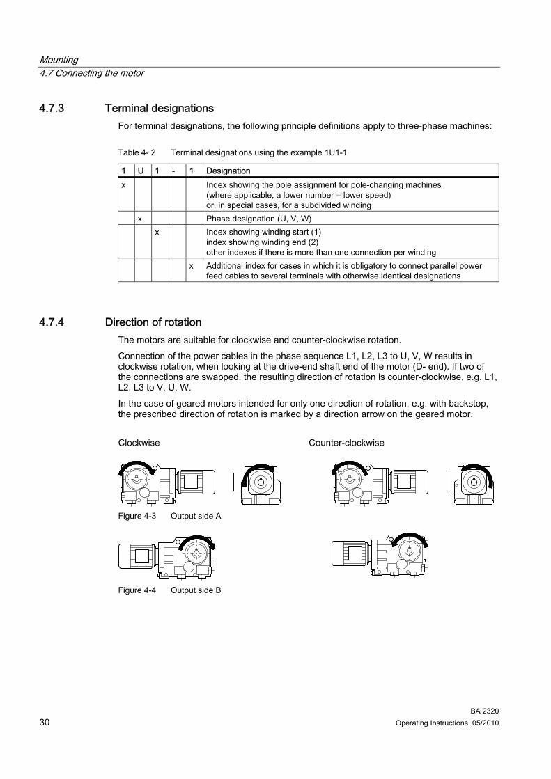
4.7.4 Direction of rotation The motors are suitable for clockwise and counter-clockwise rotation. Connection of the power cables in the phase sequence L1, L2, L3 to U, V, W results in clockwise rotation, when looking at the drive-end shaft end of the motor (D- end). If two of the connections are swapped, the resulting direction of rotation is counter-clockwise, e.g. L1, L2, L3 to V, U, W. In the case of geared motors intended for only one direction of rotation, e.g. with backstop, the prescribed direction of rotation is marked by a direction arrow on the geared motor. Clockwise Counter-clockwise
Figure 4-3 Output side A
Figure 4-4 Output side B

Mounting 4.7 Connecting the motor
BA 2320 Operating Instructions, 05/2010 31
Table 4- 3 Direction of rotation of the geared motors with a view of the output shaft
Direction of rotation Gearbox type View of Output shaft Input shaft Right Right Z18 … 188 Output shaft Left Left Right Left D18 … 188 Output shaft Left Right Right Right FZ28, 38B … 188B,
208 A side of the output shaft
Left Left Right Left FD28, 38B … 188B,
208 A side of the output shaft
Left Right Right Right B28 … 38 A side of the output shaft Left Left Right Left K38 … 88 A side of the output shaft Left Right Right Right K108 … 188 A side of the output shaft Left Left Right Left K38 … 188 B side of the output shaft Left Right Right Right C28 … 88 A side of the output shaft Left Left
4.7.5 Connecting the cables in the terminal box
Note The direct contact between the cable lug surfaces and the contact nuts ensures that the connection can carry current.
In the case of terminals with terminal clips, the conductors are spread out in such a way that the terminating heights on both sides of the web are about the same. This method of connection requires that a single conductor be bent into a U shape or connected with a cable lug. The same applies to the inner and outer terminals of the ground conductor. The choice of cable lug size must match the required conductor cross-section and the bolt size. A sloped / angular arrangement is only permitted provided the required air clearances and creepage distances are adhered to. Remove the insulation from the conductor ends so that the remaining insulation is almost long enough to reach the cable lug.

Mounting 4.7 Connecting the motor
BA 2320 32 Operating Instructions, 05/2010
4.7.6 Assembly and laying of cables
Note The screw-type connections must have been matched to the connecting cables used (armoring, braid, shield).
Screw the screw-type connection into the housing or fasten with a nut.
4.7.7 Tightening torque for bolts in electrical connections
Terminal board connection Please observe the following tightening torques for bolts on the terminal box and grounding conductors.
Table 4- 4 Tightening torque for terminal board connection
Tightening torque Tightening torque min. max. min. max.
Thread size
[Nm] [Nm]
Thread size
[Nm] [Nm] M4 0.8 1.2 M10 9 13 M5 1.8 2.5 M12 14 20 M6 2.7 4 M16 27 40 M8 5.5 8
Cable gland
CAUTION Damage to the cable jacket due to too high a tightening torque for different cable jacket materials. Use a lower tightening torque for different cable jacket materials.
For metal or plastic cable glands, please use the following tightening torques for direct mounting. The O-ring cross-section is 2 mm.
Table 4- 5 Tightening torque for cable gland
Tightening torque ±10 % Tightening torque ±10 % Metal Plastic Metal Plastic
Thread size
[Nm] [Nm]
Thread size
[Nm] [Nm] M12 x 1.5 8 M32 x 1.5 M16 x 1.5 10 M40 x 1.5
18
M20 x 1.5 M50 x 1.5 M25 x 1.5
12
4
M63 x 1.5 20
6
Mounting 4.7 Connecting the motor
BA 2320 Operating Instructions, 05/2010 33
4.7.8 Forced ventilation (optional)
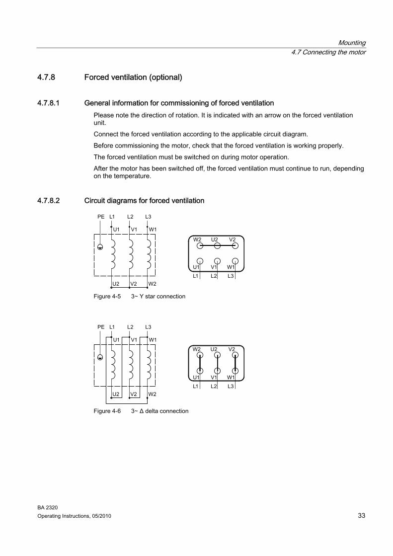
4.7.8.1 General information for commissioning of forced ventilation Please note the direction of rotation. It is indicated with an arrow on the forced ventilation unit. Connect the forced ventilation according to the applicable circuit diagram. Before commissioning the motor, check that the forced ventilation is working properly. The forced ventilation must be switched on during motor operation. After the motor has been switched off, the forced ventilation must continue to run, depending on the temperature.
4.7.8.2 Circuit diagrams for forced ventilation
Figure 4-5 3∼ Y star connection
Figure 4-6 3∼ Δ delta connection
Mounting 4.7 Connecting the motor
BA 2320 34 Operating Instructions, 05/2010
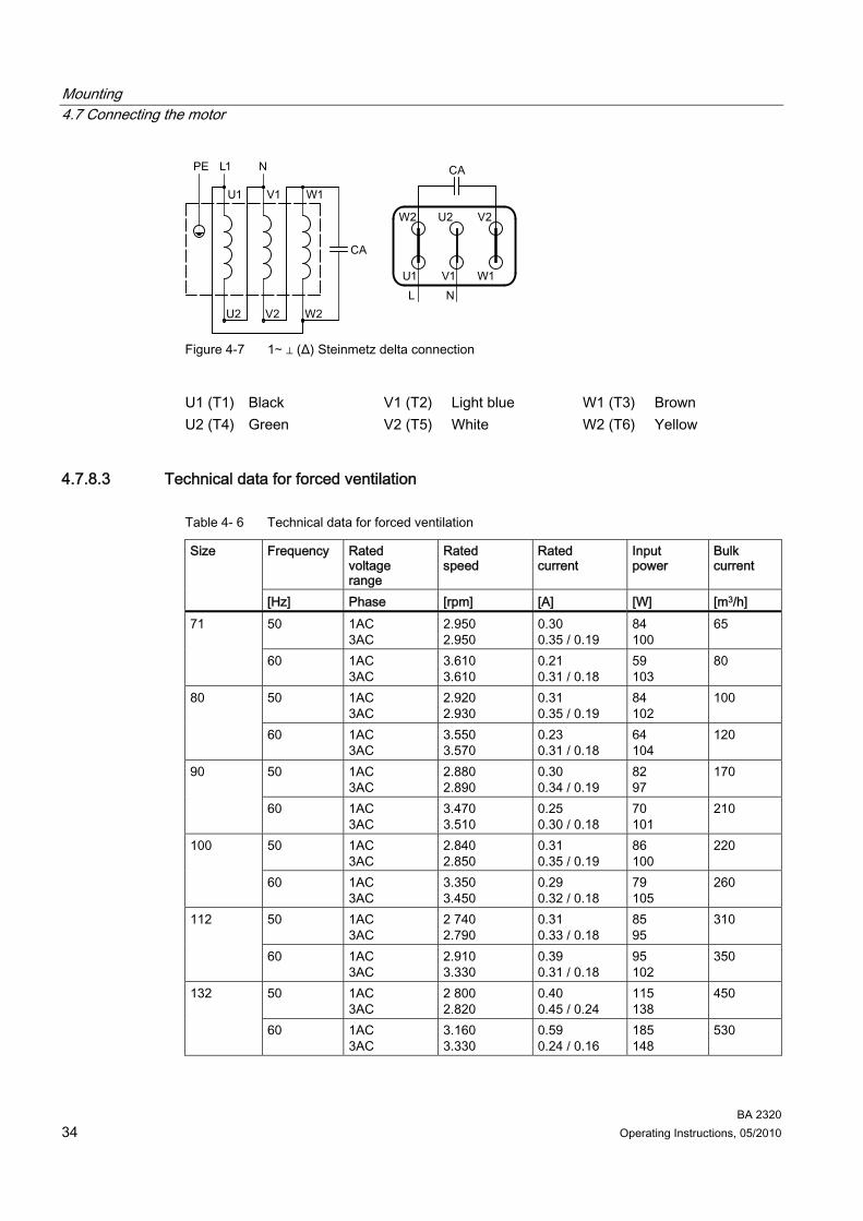
Figure 4-7 1∼ ⊥ (Δ) Steinmetz delta connection
U1 (T1) Black V1 (T2) Light blue W1 (T3) Brown U2 (T4) Green V2 (T5) White W2 (T6) Yellow
4.7.8.3 Technical data for forced ventilation
Table 4- 6 Technical data for forced ventilation
Frequency Rated voltage range
Rated speed
Rated current
Input power
Bulk current
Size
[Hz] Phase [rpm] [A] [W] [m3/h] 50 1AC
3AC 2.950 2.950
0.30 0.35 / 0.19
84 100
65 71
60 1AC 3AC
3.610 3.610
0.21 0.31 / 0.18
59 103
80
50 1AC 3AC
2.920 2.930
0.31 0.35 / 0.19
84 102
100 80
60 1AC 3AC
3.550 3.570
0.23 0.31 / 0.18
64 104
120
50 1AC 3AC
2.880 2.890
0.30 0.34 / 0.19
82 97
170 90
60 1AC 3AC
3.470 3.510
0.25 0.30 / 0.18
70 101
210
50 1AC 3AC
2.840 2.850
0.31 0.35 / 0.19
86 100
220 100
60 1AC 3AC
3.350 3.450
0.29 0.32 / 0.18
79 105
260
50 1AC 3AC
2 740 2.790
0.31 0.33 / 0.18
85 95
310 112
60 1AC 3AC
2.910 3.330
0.39 0.31 / 0.18
95 102
350
50 1AC 3AC
2 800 2.820
0.40 0.45 / 0.24
115 138
450 132
60 1AC 3AC
3.160 3.330
0.59 0.24 / 0.16
185 148
530

Mounting 4.7 Connecting the motor
BA 2320 Operating Instructions, 05/2010 35
Frequency Rated voltage range
Rated speed
Rated current
Input power
Bulk current
Size
[Hz] Phase [rpm] [A] [W] [m3/h] 50 1AC
3AC 2 670 2 760
0.93 0.71 / 0.40
225 220
780 160
60 1AC 3AC
- 3.130
- 0.85 / 0.51
- 280
880
50 1AC 3AC
2.670 2.760
0.93 0.71 / 0.40
225 220
860 180
60 1AC 3AC
- 3.130
- 0.85 / 0.51
- 280
50 1AC 3AC
2 670 2.760
0.93 0.85 / 0.51
225 220
950 200
60 1AC 3AC
- 3.130
- 0.71 / 0.40
- 280
-
50 3AC 2.720 2.00 / 1.15 450 - 225 60 3AC 3.320 1.05 520 - 50 3AC 2.720 2.00 / 1.15 450 - 250 60 3AC 3.320 1.05 520 - 50 3AC 2.720 2.00 / 1.15 450 - 280 60 3AC 3.320 1.05 520 - 50 3AC 2.720 2.00 / 1.15 450 - 315 60 3AC 3.320 1.05 520 -
Table 4- 7 Rated voltage range of motor
Frequency Rated voltage range Size [Hz] Phase [V] Switching
1AC 220 … 277 ⊥ (Δ) 50 3AC 220 … 290 / 380 … 500 Δ / Y 1AC 220 … 277 ⊥ (Δ)
71 … 112
60 3AC 220 … 332 / 380 … 575 Δ / Y 1AC 230 … 277 ⊥ (Δ) 50 3AC 220 … 290 / 380 … 500 Δ / Y 1AC 230 … 277 ⊥ (Δ)
132 … 200
60 3AC 220 … 332 / 380 … 575 Δ / Y
50 3AC 220 … 240 / 380 … 420 Δ / Y 225 … 315 60 3AC 440 … 480 Δ / Y

Mounting 4.7 Connecting the motor
BA 2320 36 Operating Instructions, 05/2010
4.7.9 Operation on the converter
Permissible voltage stress
CAUTION Converters without an output filter cause damage to the motor insulation due to impermissible voltage peaks. Reduce the maximum motor voltage to noncritical values by using an output filter on the converter.
① Standard insulation ② Reinforced insulation Upk Pulse voltage t Rise time Figure 4-8 Limit curves for the pulse voltage
Bearing currents Additional bearing currents due to steep voltage edges when switching. Without output filters, significant voltage variations can occur on the winding terminals. Make sure the drive system is installed in accordance with EMC requirements.
Mechanical stress and grease lifetime High speeds that exceed the rated speed and the resulting increased vibrations alter the mechanical running smoothness and the bearings are subjected to increased stress. This reduces the service life of the grease and bearings.
Optional add-on units Connect the temperature sensor of the monitoring system and the anti-condensation heating according to the appropriate circuit diagram. Only switch on the anti-condensation heating after the motor has been switched off.

BA 2320 Operating Instructions, 05/2010 37
Commissioning 55.1 Checking the insulation resistance
Work on power installations must only be carried out by specialists.
WARNING Secure the drive unit to prevent it from being started up unintentionally. Place a warning notice at the drive connection point.
WARNING All covers which are designed to prevent active or rotating parts from being touched, or which are necessary to ensure correct cooling, must be installed prior to commissioning.
DANGER During the measurement, and immediately afterwards, hazardous voltage levels are applied on some of the terminals and they should not be touched. Carry out a check on the power cables connected to ensure that no voltage can be applied.
CAUTION The insulation resistance needs to be checked prior to commissioning and again after any extended periods of storage or periods during which the equipment is not in operation. Before measuring the insulation resistance, read the manual for the insulation resistance meter you are going to use. Disconnect any main circuit cables already connected from the terminals before measuring the insulation resistance.
NOTICE If the critical insulation resistance is less than or equal to this value, the windings must be dried or, if the fan is removed, cleaned thoroughly and dried. Note that the insulation resistance of dried, clean windings is lower than that of warm windings. The insulation resistance can only be properly assessed after conversion to the reference temperature of +25 °C. If the measured value is close to the critical value, you must subsequently check the insulation resistance at appropriately frequent intervals.
Commissioning 5.1 Checking the insulation resistance
BA 2320 38 Operating Instructions, 05/2010
Wherever possible, measure the minimum insulation resistance of the winding to the motor housing at a winding temperature of +20 °C to +30 °C. Other values for the insulation resistance apply for temperatures outside this range. When making the measurement, wait until the final resistance value is reached, approx. 1 minute. Measure the critical insulation resistance at the operating temperature of the winding.
Limit values The following limit values are valid for the insulation resistance at a rated voltage of UN < 2 kV and a winding temperature of +25 °C. 500 V Measuring circuit voltage 10 MΩ Minimum insulation resistance with new, cleaned or repaired windings 0.5 MΩ/kV Critical specific insulation resistance after a long operating time Observe the following: ● When measuring at winding temperatures other than +25 °C, the measured value must
be converted to the reference temperature of +25 °C. The insulation resistance is halved for every 10 K increase in temperature, and it is doubled for every 10 K decrease in temperature.
● If the insulation resistance is close to or below the minimum value, the cause could be humidity and dirt accumulation. The windings must then be dried.
● During operation, the insulation resistance of the windings can fall to the critical insulation resistance due to ambient and operational influences. The critical insulation resistance for a +25 °C winding temperature can be calculated, depending on the rated voltage, by multiplying the rated voltage (kV) by the specific critical resistance value (0.5 MΩ/kV); e.g. critical resistance for rated voltage (UN) 690 V: 690 V x 0.5 MΩ/kV = 0.345 MΩ.

Commissioning 5.2 Commissioning the motor
BA 2320 Operating Instructions, 05/2010 39
5.2 Commissioning the motor
CAUTION Protect the motor from overloading. Do not exceed or undershoot limit speeds, e.g. during operation with a backstop.
CAUTION With a backstop: Running in the wrong direction of rotation can damage the geared motor. Check the direction of rotation before starting up. Turn the input side or motor over manually. Use the phase sequence to check the direction of motor rotation and swap the two external conductors if necessary.
CAUTION For brakes with lockable manual release: No braking effect for lockable manual brake release lever. The brake is then permanently released. Before commissioning the geared motor, ensure that the brake can be applied. We recommend you unscrew and remove the manual brake release lever.
Note With a brake motor: Before commissioning, check the uniformity of the rated air gap of the brake – in a current-free state – in three places, using a feeler gauge between the armature disk and the magnet part.
Note It may be necessary to perform additional checks and tests in accordance with the specific, on-site situation.

Commissioning 5.2 Commissioning the motor
BA 2320 40 Operating Instructions, 05/2010
After checking and ensuring the following items, you can start commissioning the motor: ● Compare the details on the rating plate with the operating conditions. ● Compare the voltage and frequency of the motor with the supply network values. ● Check the direction of rotation. ● For Υ / Δ start-up, ensure that the switchover from star to delta only takes place once the
Y-level starting current has decayed. ● Check the electrical connections are fixed securely. ● Check all the touch protection measures for both moving and live parts. ● Check that the monitoring instruments are connected and set correctly. ● Check the coolant temperature. ● Check any supplementary equipment present. ● Check the air inlet points and cooling surfaces are clean. ● Create appropriate grounding and equipotential bonding connections. ● Secure the motor properly. ● Check that the ventilation is not impeded and that the discharged air - also from adjacent
assemblies - cannot be drawn back in. ● Check the belt tension if there is a belt drive. ● Seal the terminal box cover and seal the cable entries.

BA 2320 Operating Instructions, 05/2010 41
Operation 6
CAUTION In the event of changes during operation, the drive unit must be switched off immediately. Use the fault table in the section titled "Faults, causes, and remedies" to determine the cause of the fault. Remedy faults or have faults remedied.
Check the motor during operation for: ● Excessive operating temperature ● Changes in the motor noise level.
Operation
BA 2320 42 Operating Instructions, 05/2010

BA 2320 Operating Instructions, 05/2010 43
Faults, causes and remedies 7
Note Faults and malfunctions occurring during the warranty period and requiring repair work on the geared motor must be remedied only by Technical Support. In the case of faults and malfunctions occurring after the warranty period, the cause of which cannot be precisely identified, we advise our customers to contact our Technical Support. If you need the help of our Technical Support, please provide the following information: • Data on the rating plate • Nature and extent of the fault • Suspected cause.
Table 7- 1 Faults, causes and remedies
Faults Causes Remedy Too much grease in bearing Remove the excess grease Bearing contaminated Replace bearing Belt tension too high Reduce belt tension Coupling forces pull or push Align the motor precisely, correct the
coupling Coolant temperature above +40 °C Adjust the cooling air to the right
temperature The bearing grease has a dark color
Check for bearing currents
Not enough grease in bearing Lubricate as prescribed by the manufacturer
Bearing overheated
Incorrect motor installation Check the motor type of construction Not enough grease in bearing Lubricate as prescribed by the
manufacturer Incorrect motor installation Check the motor type of construction
Bearing noise
Brinelling on the inner ring of the bearing, e.g. due to motor startup with locked bearing
Replace bearing, prevent vibration when motor is stationary

Faults, causes and remedies
BA 2320 44 Operating Instructions, 05/2010
Faults Causes Remedy Coupling forces pull or push Align the motor precisely, correct the
coupling Incorrect motor installation Check the motor type of construction Out of balance due to belt pulley or coupling
Balance precisely
Motor running unevenly
Machine mounting too weak Check the mounting Counter torque too high Check the motor torque and the load
torque Low line voltage Check line conditions Phase interruption Check the connection network
Motor does not ramp up
Circuitry incorrect Observe the circuit diagram and rating plate
Circuitry incorrect Observe the circuit diagram and rating plate
Overload Compare data on the rating plate Switching frequency too high Observe the rated duty Insufficient ventilation Check the cooling air ducts, check the
direction of rotation
Motor overheated
Cooling air ducts contaminated Clean cooling air ducts Counter torque too high Check the motor torque and the load
torque Low line voltage Check line conditions Phase interruption Check the connection network Circuitry incorrect Observe the circuit diagram and rating
plate
Significant drop in speed
Overload Compare data on the rating plate Phase interruption Check the connection network Circuitry incorrect Observe the circuit diagram and rating
plate Overload Compare data on the rating plate Switching frequency too high Observe the rated duty Winding and terminal short-circuit Measure the insulation resistance
Protective equipment trips
Startup time is exceeded Check the power-up conditions

BA 2320 Operating Instructions, 05/2010 45
Service and maintenance 88.1 General notes about maintenance
WARNING Switch off the power to the drive unit. Secure the drive unit to prevent it from being started up unintentionally. Place a warning notice at the drive connection point.
CAUTION Service and maintenance must only be carried out by properly trained and authorized personnel. Only genuine parts supplied by Siemens Geared Motors GmbH can be used for servicing and maintenance.
All inspection, maintenance, and repair work must be carried out with care by trained personnel only. Observe the information in Section General information and safety notes (Page 7).
Service and maintenance 8.2 Description of maintenance and repair work
BA 2320 46 Operating Instructions, 05/2010
8.2 Description of maintenance and repair work
8.2.1 Locking the manual release of the brake (optional)
CAUTION No braking effect for lockable manual brake release lever. The brake is then permanently released. Before commissioning the geared motor, ensure that the brake can be applied. We recommend you unscrew and remove the manual brake release lever during operation.
The lockable manual release of the brake must be kept in the released state for maintenance work.
Locking the manual brake release lever 1. Screw on the manual brake release lever. 2. Bring the manual brake release lever into the position in which the brake is released. 3. Tighten the locking screw far enough so that the manual brake release lever cannot
return to the unreleased position. You can now start maintenance work on the plant with a released brake.
Releasing the lock 1. Unscrew the locking screw far enough so that the brake can completely return to the
unreleased position. The gap between the locking screw and the manual brake release lever must be 2 to 5 mm.
2. Unscrew the manual brake release lever. You have ensured that the manual brake release is no longer locked.
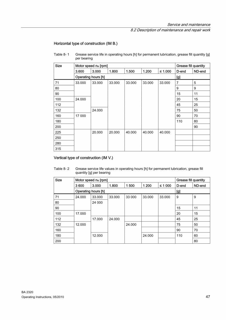
8.2.2 Lubrication The bearings of the standard version surface-cooled motors up to size 200 are permanently lubricated. If this is not the case, this is indicated by a warning notice on the motor. The specified grease service life values are valid for an ambient temperature of max. +40 °C. For every 10 °C increase in temperature, the grease service life is reduced by a factor of 0.7 of the value in the table (max. +20 °C = factor 0.5). At an ambient temperature of +25 °C, the grease service life can be expected to be doubled. Irrespective of the number of operating hours, renew the roller bearing grease or the bearing (2Z bearing) after 3 or 4 years at the latest.
Service and maintenance 8.2 Description of maintenance and repair work
BA 2320 Operating Instructions, 05/2010 47
Horizontal type of construction (IM B.)
Table 8- 1 Grease service life in operating hours [h] for permanent lubrication, grease fill quantity [g] per bearing
Motor speed nN [rpm] Grease fill quantity 3.600 3.000 1.800 1.500 1.200 ≤ 1.000 D-end ND-end
Size
Operating hours [h] [g] 71 7 5 80 9 9 90
33.000
15 11 100 20 15 112
33.000
45 25 132
24.000
75 50 160 90 70 180 80 200
17 000 24.000
33.000 33.000 33.000 33.000
110 90
225 250 280 315
20.000 20.000 40.000 40.000 40.000
Vertical type of construction (IM V.)
Table 8- 2 Grease service life values in operating hours [h] for permanent lubrication, grease fill quantity [g] per bearing
Motor speed nN [rpm] Grease fill quantity 3 600 3.000 1.800 1 500 1 200 ≤ 1 000 D-end ND-end
Size
Operating hours [h] [g] 71 33.000 80
9 9
90
24.000
15 11 100
24 000 33.000 33 000 33.000 33.000
20 15 112
17.000 45 25
132 75 50 160
17.000
90 70 180 60 200
12.000
12.000
24.000 24.000
24.000
110 80

Service and maintenance 8.2 Description of maintenance and repair work
BA 2320 48 Operating Instructions, 05/2010
8.2.3 Cleaning the motor
CAUTION Dust deposits prevent heat radiation and cause high housing temperatures. Keep the geared motor free from dirt and dust.
CAUTION Do not use a high-pressure cleaning appliance to clean the geared motor. Do not use tools with sharp edges.
Switch off the power supply to the drive unit before cleaning it.
8.2.4 Checking tightness of fastening bolts
Note Replace damaged headless screws with new screws of the same type and strength class.
Switch off the power to the drive unit and use a torque wrench to check the seating of all fastening bolts. The general tolerance for the tightening torque in Nm is 10%. The friction coefficient is 0.14 μ.
Table 8- 3 Tightening torques for fastening bolts
Tightening torque at strength class 8.8 10.9 12.9
Thread size
[Nm] [Nm] [Nm] M4 3 4 5 M5 6 9 10 M6 10 15 18 M8 25 35 41 M10 50 70 85 M12 90 120 145 M16 210 295 355 M20 450 580 690 M24 750 1,000 1,200 M30 1,500 2,000 2,400 M36 2,500 3,600 4,200

Service and maintenance 8.2 Description of maintenance and repair work
BA 2320 Operating Instructions, 05/2010 49
8.2.5 Inspection of the motor Carry out a scheduled inspection of the geared motor once a year in accordance with the possible criteria listed in Section Faults, causes and remedies (Page 43). Check the geared motor in accordance with the criteria set out in Section General information and safety notes (Page 7). Touch up damaged paintwork carefully.
8.2.6 Servicing the brake
8.2.6.1 Wear of the spring-operated brake The friction lining and the mechanical components of the brake are subject to wear due to their function. For safe and fault-free operation, the brake must be checked regularly, adjusted and, if necessary, replaced. The following table describes the different causes of wear and their effects on the spring-operated brake components. To be able to calculate the service life of the rotor and the brake and to determine the stipulated maintenance intervals, the important influencing factors must be quantified. Here the most important factors are the work of friction transformed, the starting speed of the braking and the frequency of switching. Should several of the causes of wear to the friction lining listed occur at the same time in a single application, the influencing factors should be added together for the wear calculation.
Table 8- 4 Causes of wear to the spring-operated brake
Component Cause Effect Influencing factor Operational braking Emergency stops Overlap wear when starting up and stopping the geared motor Active braking by the motor supported by the brake (quick stop) Low speed and type of construction 'motor at top'
Work of friction transformed
Friction lining
Start-up wear for motor mounting position with vertical shaft even when the brake is released
Friction lining wear
Number of start / stop cycles

Service and maintenance 8.2 Description of maintenance and repair work
BA 2320 50 Operating Instructions, 05/2010
Component Cause Effect Influencing factor Armature disk and flange
Friction of the brake lining
Run-in of armature disk and flange
Work of friction transformed
Braking rotor gear teeth Relative movement and impacts between rotor and hub
Wear of the teeth (primarily on the rotor side)
Number of start / stop cycles
Support of the armature disk
Load change and impacts in the backlash between the armature disk, sleeve screws and guide pins
Deflection of armature disk, sleeve screws and pins
Number of start / stop cycles, strength of braking torque
Springs Axial load cycle and shear stresses in the springs due to radial backlash in the armature disk
Decrease in the spring force or fatigue failure
Number of switching operations of the brake
8.2.6.2 Maintenance intervals for the brake For safe and fault-free operation, the spring-operated brake must be regularly checked and maintained. For operational braking, the necessary maintenance intervals are primarily a result of the loading on the brake in the application. When calculating the maintenance interval, all the causes of wear must be taken into account. For low loaded brakes, e.g. holding brakes with emergency stop, a regular inspection at fixed time intervals is recommended. A lack of brake maintenance can lead to operating faults, production outage or damage to the plant. For this reason, a maintenance plan must be stipulated for each application, appropriate to the operating conditions and loading of the brake. The following table lists the stipulated maintenance intervals and maintenance work to be carried out for the pneumatic brake.
Table 8- 5 Maintenance interval for the brake
Brake Maintenance interval According to service life calculation Otherwise every six months
Operational brake
After 4.000 operating hours at the latest Minimum every 2 years After 10 million cycles at the latest
Holding brake with emergency stop
Shorter intervals for frequent emergency stops

Service and maintenance 8.2 Description of maintenance and repair work
BA 2320 Operating Instructions, 05/2010 51
8.2.6.3 Adjusting the air gap
DANGER Switch off the power to the drive unit. The brake must be torque-free. Secure the drive unit to prevent it from being started up unintentionally. Place a warning notice at the drive connection point.
WARNING Decrease of braking effect due to contamination. Do not allow oil or grease to come into contact with friction surfaces.
Figure 8-1 Setting dimension s
Procedure 1. Remove the fan cover. 2. Loosen the fastening screws of the brake. 3. Screw the sleeve screws further into the magnet part using an open-ended spanner. 4. Tighten the fastening screws of the brake. 5. Check the air gap sLü, in the vicinity of the screws using a feeler gauge. 6. Rectify the air gap sLü if necessary and check it again. 7. When combined with manual brake release:
Check the setting dimension "s" and correct "s" if necessary. 8. Mount the fan cover. You have now set the air gap.

Service and maintenance 8.2 Description of maintenance and repair work
BA 2320 52 Operating Instructions, 05/2010
Table 8- 6 Air gap values
Max. air gap at Rated air gap sLüNenn (+0.1 / -0.05) Standard
excitation sLümax.
Overexcitation sLümax.
Setting dimension "s"
Brake type
[mm] [mm] [mm] [mm] L4/1.4 0.65 0.65 L4/2 0.6 0.6 L4/3 0.55 0.55 L4 0.5 0.5 L4/5 0.4 0.4 L8/3, L8/4 0.6 0.6 L8/5, L8/6.3 0.55 0.55 L8 0.5 0.5 L8/10 0.45 0.45 L16/8, L16/10, L16/13, L16 0.6 0.6 L16/20
0.2
0.5 0.5
1.0
L32/14, L32/18, L60/25 0.9 0.9 L32/23, L60/38 0.85 0.85 L32, L60/50 0.75 0.75 L32/40, L60 0.65 0.65 L80/25, L80/35, L80/50, L80/63, L80
0.9 0.9
L80/100
0.3
0.7 0.7
1.5
L150/60, L150/80, L150/100, L150/125, L150, L260/100, L260/145, L260/180, L260/200, L260/240, L260
1.2 1.2
L260/315
0.4
1.05 1.05
2.0
L400/265, L400/300, L400/360, L400
1.5 1.5
L400/600
0.5
0.9 0.9
2.5
Table 8- 7 Tightening torque for tightening bolt
Brake type Tightening torque Siemens INTORQ BA BFK458
Thread size [Nm]
L4 (06E) 3 x M4 2.8 L8 (08E) 3 x M5 5.5 L16 (10E) 3 x M6 9.5 L32 (12E) 3 x M6 9.5 L60, L80 (14E), (16E) 3 x M8 23 L150 (18E) 6 x M8 23 L260, L400 (20E), (25E) 6 x M10 46

Service and maintenance 8.2 Description of maintenance and repair work
BA 2320 Operating Instructions, 05/2010 53
8.2.6.4 Replacing the friction lining
DANGER Switch off the power to the drive unit. The brake must be torque-free. Secure the drive unit to prevent it from being started up unintentionally. Place a warning notice at the drive connection point.
Procedure 1. Remove the fan cover.
When combined with manual release: Unscrew the manual brake release lever. With forced ventilation: Remove the fan cover with forced ventilation.
2. Remove the connection cable. 3. Remove the fan locking ring and pull out the fan. 4. Loosen the brake screws evenly and remove them completely. 5. Pull the rotor completely off the hub. 6. Check the teeth on the hub. 7. Check the friction surface on the bearing shield. If there is severe striation on the friction
plate or flange, replace the friction plate or flange. Rework the friction surfaces if there is severe striation on the bearing shield.
8. Measure the thickness of the new rotor and the head height of the sleeve screws with a caliper gauge.
9. Calculate the gap between the magnet part and the armature disk as follows: Gap = Rotor thickness + sLüNenn - head height.
10. Unscrew the sleeve screws evenly until the calculated gap between the magnet part and the armature disk is set.
11. Mount the new rotor and the magnet part and adjust it. 12. Connect the connection cable. 13. Mount the fan cover. You have now replaced the friction lining of the brake.
Service and maintenance 8.2 Description of maintenance and repair work
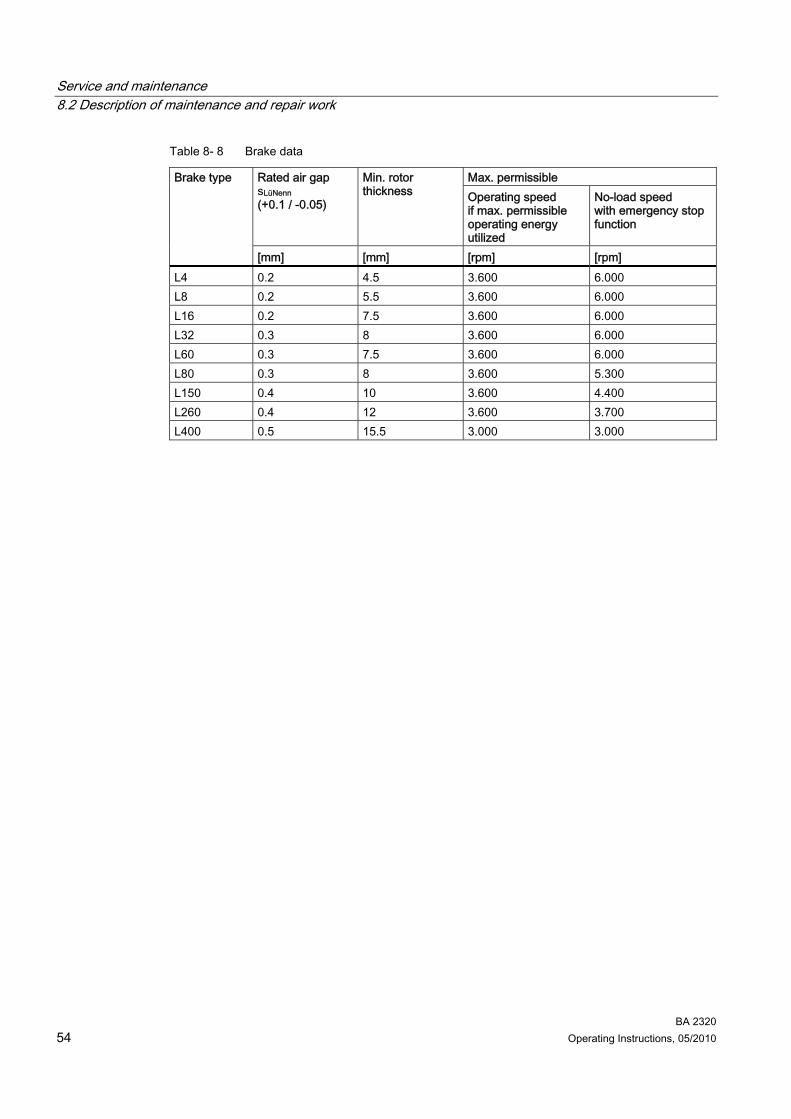
BA 2320 54 Operating Instructions, 05/2010
Table 8- 8 Brake data
Max. permissible Rated air gap sLüNenn (+0.1 / -0.05)
Min. rotor thickness Operating speed
if max. permissible operating energy utilized
No-load speed with emergency stop function
Brake type
[mm] [mm] [rpm] [rpm] L4 0.2 4.5 3.600 6.000 L8 0.2 5.5 3.600 6.000 L16 0.2 7.5 3.600 6.000 L32 0.3 8 3.600 6.000 L60 0.3 7.5 3.600 6.000 L80 0.3 8 3.600 5.300 L150 0.4 10 3.600 4.400 L260 0.4 12 3.600 3.700 L400 0.5 15.5 3.000 3.000

BA 2320 Operating Instructions, 05/2010 55
Disposal 9
DANGER Incorrect disposal of used oil is a threat to the environment and health. After use, oil must be taken to a used oil collection point. The addition of foreign material such as solvents and brake and cooling fluid is prohibited. Avoid prolonged contact with the skin.
Empty the used oil from the gearbox. The used oil must be collected, stored, transported and disposed of in accordance with regulations. Do not mix polyglycols with mineral oil. Polyglycols must be disposed of separately. Please observe country-specific laws. Under German law, oils with different disposal codes may not be mixed with one another to allow optimal treatment of the oil (§4 VI Used Oil). Collect and dispose of used oil in accordance with regulations. Remove oil spillages immediately with an oil-binding agent in compliance with environmental requirements. Dispose of the housing parts, gears, shafts, and roller bearings of the geared motor as steel scrap. The same applies to grey cast iron parts, if no separate collection is made. The worm wheels are made partly from non-ferrous metal. Dispose of them accordingly. Dispose of the packing material according to regulations or recycle it.
Table 9- 1 Disposal codes for gear oils
Type of oil Name Disposal code Mineral oil CLP ISO VG220 13 02 05 Polyglycols CLP ISO PG VG220
CLP ISO PG VG460 13 02 08
Polyalphaolefins CLP ISO PAO VG68 CLP ISO PAO VG220 CLP ISO H1 VG460
13 02 06
Biologically degradable oils CLP ISO E VG220 13 02 07

Disposal
BA 2320 56 Operating Instructions, 05/2010

BA 2320 Operating Instructions, 05/2010 57
Technical data 1010.1 Type designation
Table 10- 1 Example of the type designation structure
Example: LA 100L 4/2 F - L16NH Motor type LA Size 100L Number of poles 4/2 Special features F Mounted unit L16NH
Table 10- 2 Type designation code
Motor type LA / LG AC induction motor, integrated LAI / LGI AC induction motor with IEC flange Special features E High efficiency F Forced ventilation I High inertia fans W Protective canopy IN Incremental encoder IR Resolver IA Absolute encoder IV Encoder mount prepared D Handwheel Mounted unit L, KFB Spring pressure single disk DC brake 16 Size = rated braking torque ../10 Set braking torque N Standard version G Enclosed version H, HA Manual brake release, lockable manual brake release M Microswitch

Technical data 10.2 General technical data
BA 2320 58 Operating Instructions, 05/2010
10.2 General technical data The most important technical data appears on the rating plate of the gearboxes and geared motors. This data, together with the contractual agreements for the geared motors, determines the limits of intended use. In the case of geared motors, a rating plate attached to the motor usually indicates the data for the entire drive. In certain cases separate rating plates are mounted on the gearbox and the motor.
SIEMENSSIEMENS
13
273032
31 3835
25 2636 37
393433 40 41 42
28
1521 22 23 24
29
1416 19 20
3479 10 11 12
17 18
5 6
21
8
50Hz
50Hz29/16.74A15kW IE1-90%
cosPhi 0.84 28.6A60Hz
100Nm 190-240V AC460V Y
cosPhi 0.871460/min 15kW 1755/min
400/690V
1266Nm3~Mot. ThCl.155(F) TP-PTC
D/Y
113/minfB=1.5 1264Nm fB=1.5
KAF108-LA160L4-L150/100GH2KJ1506-5JR13-2FD1-ZIP55G. 6.2L OIL CLP PG VG220 i=12.9
60Hz 136/min
FDU1001/8999999 nnn 254kg
IEC60034
(IM) H-01-A
Figure 10-1 Rating plate example
1 CE marking or other marking, if required 2 Applied standard 3 Model - Type - Size 4 Order No. 5 Serial No. 6 Weight m [kg] 7 IEC 60034-5 or IEC 60529 protection 8 Type of construction (IM) 9 Oil quantity [l] main gearbox / intermediate gearbox + extruder flange 10 Type of oil 11 Oil viscosity ISO VG class to DIN 51519 / ISO 3448 12 Total transmission ratio i Frequency 1 13 Rated frequency f [Hz] 14 Speed at output n2 [rpm] 15 Torque at output T2 [Nm] 16 Service factor fB Frequency 2 17 Rated frequency f [Hz] 18 Speed at output n2 [rpm] 19 Torque at output T2 [Nm] 20 Service factor fB

Technical data 10.3 Weight
BA 2320 Operating Instructions, 05/2010 59
Motor data 21 Phase number and type of current for the motor 22 Temperature class Th.Cl. 23 Motor protection (TP) 24 Symbols (IEC 60617-2): = brake 25 Braking torque TBr [Nm] 26 Brake supply voltage U [V] Frequency 1 27 Rated frequency f [Hz] 28 Rated voltage / range U [V] 29 Circuit, graphical symbols as per DIN EN 60617 Part 6 / IEC 60617-6 30 Rated current I [A] 31 Power factor cos φ 32 Rated output P [kW], mode (if ≠ S1) 33 Efficiency class designation 34 Rated speed n1 [rpm] Frequency 2 35 Rated frequency f [Hz] 36 Rated voltage / range U [V] 37 Rated current I [A] 38 Power factor cos φ 39 Circuit, graphical symbols as per DIN EN 60617 Part 6 / IEC 60617-6 40 Rated output P [kW], mode (if ≠ S1) 41 Efficiency class designation 42 Rated speed n1 [rpm]
10.3 Weight The weight of the entire geared motor is given in the shipping papers. If the weight exceeds 30 kg, the weight of the entire geared motor is indicated on the rating plate of the gearbox or geared motor. Where there are several rating plates on one geared motor, the specification on the main gearbox is decisive. The weight specification refers only to the condition of the product on delivery.

Technical data 10.3 Weight
BA 2320 60 Operating Instructions, 05/2010

BA 2320 Operating Instructions, 05/2010 61
Spare parts / Accessories 1111.1 Stocking of spare parts
By stocking the most important spare and wearing parts on site, you can ensure that the gearbox or geared motor is ready for use at any time.
CAUTION Please note that spare parts and accessories not supplied by us have not been tested or approved by us. The installation and / or use of such products can therefore have a negative impact on the design characteristics of the geared motor and might consequently impair the active and / or passive safety features of the machine. Siemens Geared Motors GmbH will accept no liability or warranty whatsoever for damage occurring as a result of the use of non-original spare parts or accessories.
We can only accept liability for original spare parts supplied by Siemens Geared Motors GmbH. Please note that single components often have special production and supply specifications. We always supply spare parts which meet state-of-the-art technical standards and comply with the latest legal requirements. Please state the following data when ordering spare parts:
● Serial no. see rating plate ⑤
● Type designation see rating plate ③
● Part no. (3-digit item no. from spare parts list, 6-digit code no. or 7-digit article no.) ● Quantity
SIEMENSSIEMENS
13
273032
31 3835
25 2636 37
393433 40 41 42
28
1521 22 23 24
29
1416 19 20
3479 10 11 12
17 18
5 6
21
8
50Hz
50Hz29/16.74A15kW IE1-90%
cosPhi 0.84 28.6A60Hz
100Nm 190-240V AC460V Y
cosPhi 0.871460/min 15kW 1755/min
400/690V
1266Nm3~Mot. ThCl.155(F) TP-PTC
D/Y
113/minfB=1.5 1264Nm fB=1.5
KAF108-LA160L4-L150/100GH2KJ1506-5JR13-2FD1-ZIP55G. 6.2L OIL CLP PG VG220 i=12.9
60Hz 136/min
FDU1001/8999999 nnn 254kg
IEC60034
(IM) H-01-A
Figure 11-1 Rating plate example
For motors of series 1LA/1LG with their own rating plate, the spare parts documentation in the original operating instructions applies.
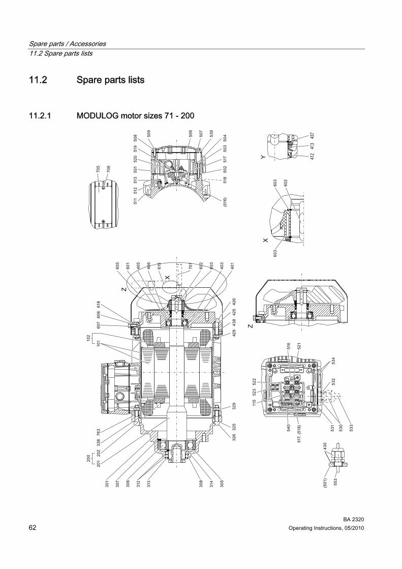
Spare parts / Accessories 11.2 Spare parts lists
BA 2320 62 Operating Instructions, 05/2010
11.2 Spare parts lists
11.2.1 MODULOG motor sizes 71 - 200
437
413
412

Spare parts / Accessories 11.2 Spare parts lists
BA 2320 Operating Instructions, 05/2010 63
101 Stator frame with core, unwound 102 Stator frame with core, wound 115 End sleeve / lug 200 Rotor 201 Shaft 202 Rotor core 301 Bearing shield 305 Supporting disk / shim 306 Bearing 307 Locking ring 308 Locking ring 312 Shaft sealing ring 313 Oil splasher 314 Supporting disk / shim 325 Screw lock 326 Bolt 329 Nut 338 Seal 401 Bearing shield 403 Bolt 405 Supporting disk / shim 406 Bearing 412 Shaft sealing ring 413 Shaft sealing ring 425 Screw lock 426 Bolt 429 Nut 430 Complete cable gland 437 Grub screw 438 Seal 501 Terminal box 502 Seal 503 Screw lock 504 Bolt 506 Terminal box 507 Seal 508 Screw lock 509 Bolt 511 Bolt 512 Screw lock 513 Supporting disk / shim 516 Connecting terminal plate 517 Bolt 518 Screw lock 519 Nut
Spare parts / Accessories 11.2 Spare parts lists
BA 2320 64 Operating Instructions, 05/2010
520 Supporting disk / shim 521 Terminal connector 522 Terminal block 523 Bolt 530 Cable gland 531 Nut 532 Seal 533 Cable / line 534 Screw plug 539 Screw lock 540 Rectifier 553 Cable / line 601 Fan 602 Supporting disk / shim 603 Locking ring 605 Fan cover 606 Screw lock 607 Bolt 615 Protective canopy 618 Damping disk 701 Featherkey 705 Rating plate 706 Bolt 763 O-ring Figure 11-2 MODULOG motor sizes 71 - 200

Spare parts / Accessories 11.2 Spare parts lists
BA 2320 Operating Instructions, 05/2010 65
11.2.2 MODULOG brake motor sizes LA71 - LA160
Figure 11-3 MODULOG brake motor sizes LA71 - LA90
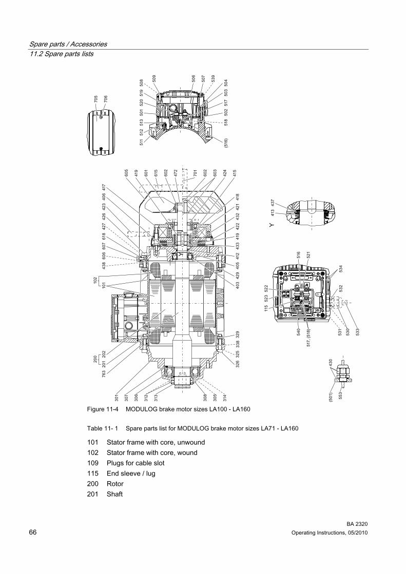
Spare parts / Accessories 11.2 Spare parts lists
BA 2320 66 Operating Instructions, 05/2010
Figure 11-4 MODULOG brake motor sizes LA100 - LA160
Table 11- 1 Spare parts list for MODULOG brake motor sizes LA71 - LA160
101 Stator frame with core, unwound 102 Stator frame with core, wound 109 Plugs for cable slot 115 End sleeve / lug 200 Rotor 201 Shaft

Spare parts / Accessories 11.2 Spare parts lists
BA 2320 Operating Instructions, 05/2010 67
202 Rotor core 301 Bearing shield 305 Supporting disk / shim 306 Bearing 307 Locking ring 308 Locking ring 312 Shaft sealing ring 313 Oil splasher 314 Supporting disk / shim 325 Screw lock 326 Bolt 329 Nut 338 Seal 401 Bearing shield 403 Bolt 405 Supporting disk / shim 406 Bearing 412 Shaft sealing ring 413 Shaft sealing ring 415 Brake 416 Screw lock 417 Bolt 418 Coupling driver 419 Locking ring 420 Supporting disk / shim 421 Featherkey 422 Supporting disk / shim 423 Manual release 424 Shaft sealing ring 425 Screw lock 426 Bolt 427 Fuse 429 Nut 430 Complete cable gland 432 Friction disk 433 Friction plate 437 Grub screw 438 Seal 441 Supporting disk / shim 472 Shaft end 501 Terminal box base

Spare parts / Accessories 11.2 Spare parts lists
BA 2320 68 Operating Instructions, 05/2010
502 Seal 503 Screw lock 504 Bolt 506 Terminal box cover 507 Seal 508 Screw lock 509 Bolt 511 Bolt 512 Screw lock 513 Supporting disk / shim 516 Complete terminal board 517 Bolt 518 Screw lock 519 Nut 520 Supporting disk / shim 521 Terminal connector 522 Terminal block 523 Bolt 530 Cable gland 531 Nut 532 Seal 533 Cable / line 534 Screw plug 539 Screw lock 540 Rectifier 553 Cable / line 601 Fan 602 Tolerance ring 603 Locking ring 605 Fan cover 606 Screw lock 607 Bolt 615 Protective canopy 618 Damping disk 701 Featherkey 702 Bolt 703 Screw lock 705 Rating plate 706 Bolt 763 O-ring

Spare parts / Accessories 11.2 Spare parts lists
BA 2320 Operating Instructions, 05/2010 69
11.2.3 MODULOG brake motor sizes LA71 - LA160 with backstop
Figure 11-5 MODULOG brake motor sizes LA71 - LA90 with backstop

Spare parts / Accessories 11.2 Spare parts lists
BA 2320 70 Operating Instructions, 05/2010
Figure 11-6 MODULOG brake motor sizes LA100 - LA160 with backstop
Table 11- 2 Spare parts list for MODULOG brake motor sizes LA71 - LA160 with backstop
101 Stator frame with core, unwound 102 Stator frame with core, wound 109 Plugs for cable slot 115 End sleeve / lug 200 Rotor
Spare parts / Accessories 11.2 Spare parts lists
BA 2320 Operating Instructions, 05/2010 71
201 Shaft 202 Rotor core 301 Bearing shield 305 Supporting disk / shim 306 Bearing 307 Locking ring 308 Locking ring 312 Shaft sealing ring 313 Oil splasher 314 Supporting disk / shim 325 Screw lock 326 Bolt 329 Nut 338 Seal 401 Bearing shield 403 Bolt 405 Spring washer 406 Bearing 412 Shaft sealing ring 425 Screw lock 426 Bolt 429 Nut 430 Complete cable gland 438 Seal 440 Backstop 469 Adapter 470 Bolt 471 Screw lock 472 Shaft end 473 Bolt 475 Featherkey 476 Supporting disk / shim 477 Locking ring 478 Protection cover 479 Sealing ring 480 Incremental encoder 501 Terminal box 502 Seal 503 Screw lock 504 Bolt 506 Terminal box
Spare parts / Accessories 11.2 Spare parts lists
BA 2320 72 Operating Instructions, 05/2010
507 Seal 508 Screw lock 509 Bolt 511 Bolt 512 Screw lock 513 Supporting disk / shim 516 Connecting terminal plate 517 Bolt 518 Screw lock 519 Bolt 520 Washer 521 Terminal connector 522 Terminal block 523 Bolt 530 Cable gland 531 Nut 532 Seal 533 Cable / line 534 Screw plug 539 Screw lock 540 Rectifier 553 Cable / line 601 Fan 602 Tolerance ring 603 Locking ring 605 Fan cover 606 Screw lock 607 Bolt 615 Protective canopy 618 Damping disk 701 Featherkey 702 Bolt 703 Screw lock 705 Rating plate 706 Bolt 763 O-ring

Spare parts / Accessories 11.2 Spare parts lists
BA 2320 Operating Instructions, 05/2010 73
11.2.4 Encoder
11.2.4.1 Encoder on fan cover
① Self-ventilated motor ② Unventilated motor 451 Cover 453 Bolt 454 Nut 472 Shaft end 480 Encoder 481 Bolt 482 Screw lock 483 Nut 485 Coupling 489 Spacer / bush 601 Fan 602 Featherkey 605 Fan cover 606 Screw lock 607 Bolt 618 Damping disk Figure 11-7 Encoder on fan cover

Spare parts / Accessories 11.2 Spare parts lists
BA 2320 74 Operating Instructions, 05/2010
11.2.4.2 Encoder in motor with forced ventilation
442 Torque arm 470 Bolt 471 Screw lock 472 Shaft end 474 Screw lock 476 Supporting disk / shim 480 Encoder 481 Bolt 482 Screw lock 602 Featherkey 605 Fan cover 606 Screw lock 607 Bolt 618 Damping disk Figure 11-8 Encoder in motor with forced ventilation

BA 2320 Operating Instructions, 05/2010 75
EC Declaration of Conformity 12
EC Declaration of Conformity according to Directive 2006/95/EC. Document No. KE DMLA 1A 05.10 The manufacturer Siemens Geared Motors GmbH, 72072 Tübingen, Germany, declares for the standard version of the motors LA / LG and LAI / LGI sizes 71 to 315: The designated products conform to the requirements of the European Directive 2006/95/EC. It has been developed and manufactured in compliance with the following European standards: ● EN 60034 with all relevant sections in the latest edition in each case ● EN 60204-1 EC Declarations of Conformity and / or manufacturer's declarations for all subassemblies, integrated and add-on units are available. These may be specifically: ● Electromagnetic brake L, KFB with connected accessories such as rectifier and switching
device SEG, SER ● External fan unit F ● Shaft encoder IA, IM, IN, RE The designated products may only be commissioned once it has been established that the machine into which they are to be incorporated meets the provisions of Directive 2006/42/EC. First use of the CE marking: 20.12.1995 First edition: 15.12.1995 Tübingen, Date May 3, 2010
Thomas Raster Head of Research & Development Electrical
Jürgen Pflaum Head of Quality Management
EC Declaration of Conformity
BA 2320 76 Operating Instructions, 05/2010


www.siemens.com/automation
Subject to change
© Siemens AG 2010
Siemens AGIndustry SectorPostfach 48 4890026 NÜRNBERGGERMANY
MOTOX geared motors on the Internet:www.siemens.com/gearedmotors
Further information