motox gearbox
TRANSCRIPT

Answers for industry.
MOTOX
MOTOX gearbox
BA 2010
Operating Instructions · 05/2011


_____________�BA 2010�
___________________
___________________
___________________
___________________
___________________
___________________
___________________
___________________
___________________
___________________
______General information and safety notes
1
Technical description
2
Incoming goods, transport, and storage 3
MOTOX
Installation 4 Gearbox
___________________
BA 2010 Commissioning 5
Operation 6
Operating Instructions7
Faults, causes and remedies
Service and maintenance 8
Disposal 9
Technical data 10
Spare parts 11
Declaration of Incorporation, Declaration of Conformity
12
05/2011

Legal information
Legal information Warning notice system
This manual contains notices you have to observe in order to ensure your personal safety, as well as to prevent damage to property. The notices referring to your personal safety are highlighted in the manual by a safety alert symbol, notices referring only to property damage have no safety alert symbol. These notices shown below are graded according to the degree of danger.
DANGER indicates that death or severe personal injury will result if proper precautions are not taken.
WARNING indicates that death or severe personal injury may result if proper precautions are not taken.
CAUTION with a safety alert symbol, indicates that minor personal injury can result if proper precautions are not taken.
CAUTION without a safety alert symbol, indicates that property damage can result if proper precautions are not taken.
NOTICE indicates that an unintended result or situation can occur if the relevant information is not taken into account.
If more than one degree of danger is present, the warning notice representing the highest degree of danger will be used. A notice warning of injury to persons with a safety alert symbol may also include a warning relating to property damage.
Qualified Personnel The product/system described in this documentation may be operated only by personnel qualified for the specific task in accordance with the relevant documentation, in particular its warning notices and safety instructions. Qualified personnel are those who, based on their training and experience, are capable of identifying risks and avoiding potential hazards when working with these products/systems.
Proper use of Siemens products Note the following:
WARNING Siemens products may only be used for the applications described in the catalog and in the relevant technical documentation. If products and components from other manufacturers are used, these must be recommended or approved by Siemens. Proper transport, storage, installation, assembly, commissioning, operation and maintenance are required to ensure that the products operate safely and without any problems. The permissible ambient conditions must be complied with. The information in the relevant documentation must be observed.
Trademarks All names identified by ® are registered trademarks of Siemens AG. The remaining trademarks in this publication may be trademarks whose use by third parties for their own purposes could violate the rights of the owner.
Disclaimer of Liability We have reviewed the contents of this publication to ensure consistency with the hardware and software described. Since variance cannot be precluded entirely, we cannot guarantee full consistency. However, the information in this publication is reviewed regularly and any necessary corrections are included in subsequent editions.
Siemens AG Copyright © Siemens AG 2011. Industry Sector Ⓟ 06/2011 Technical data subject to changePostfach 48 48 90026 NÜRNBERG GERMANY
Table of contents
1 General information and safety notes ........................................................................................................ 7
1.1 General information .......................................................................................................................7
1.2 Copyright........................................................................................................................................9
1.3 Intended use ................................................................................................................................10
1.4 Obligations of the user .................................................................................................................11
1.5 Particular type of risk and personal protective equipment...........................................................12
2 Technical description ............................................................................................................................... 13
2.1 General description......................................................................................................................13
2.2 Housing ........................................................................................................................................13
2.3 Geared components ....................................................................................................................13
2.4 Lubrication....................................................................................................................................13
2.5 Shaft bearings..............................................................................................................................13
2.6 Shaft seals ...................................................................................................................................14 2.6.1 Radial shaft sealing ring...............................................................................................................14 2.6.2 Combination shaft sealing ring (optional) ....................................................................................14
2.7 Cooling .........................................................................................................................................14
2.8 Backstop ......................................................................................................................................15
2.9 Rating plate ..................................................................................................................................16
2.10 Surface treatment ........................................................................................................................17 2.10.1 General information on surface treatment ...................................................................................17 2.10.2 Painted version ............................................................................................................................18 2.10.3 Primed version .............................................................................................................................20
3 Incoming goods, transport, and storage................................................................................................... 21
3.1 Incoming goods............................................................................................................................21
3.2 Transport......................................................................................................................................22 3.2.1 General information on transport .................................................................................................22 3.2.2 Fastening for suspended transport ..............................................................................................23
3.3 Storage.........................................................................................................................................25 3.3.1 General information for storage ...................................................................................................25 3.3.2 Storage up to 6 months................................................................................................................25 3.3.3 Storage up to 36 months with long-term preservation (optional).................................................26
4 Installation ............................................................................................................................................... 27
4.1 Unpacking ....................................................................................................................................27
4.2 General information on installation ..............................................................................................27
BA 2010 Operating Instructions, 05/2011 3

Table of contents
BA 2010 4 Operating Instructions, 05/2011
4.3 Tightening torque for fastening bolts on the gearbox ................................................................. 29
4.4 Fastening in the case of high shock loads.................................................................................. 29
4.5 Gearbox with foot mounting ........................................................................................................ 30
4.6 Gearboxes in foot or flange version ............................................................................................ 31
4.7 Gearbox with C-type housing flange........................................................................................... 31
4.8 Mounting the input or output element on the gearbox ................................................................ 34
4.9 Removing and installing the protection cover ............................................................................. 36
4.10 Removing and installing the shaft-mounted gearbox.................................................................. 38 4.10.1 General information on installing the shaft-mounted gearbox .................................................... 38 4.10.2 Removing and installing the hollow shaft.................................................................................... 39 4.10.2.1 Mounting the hollow shaft ........................................................................................................... 39 4.10.2.2 Removing the hollow shaft with parallel key ............................................................................... 41 4.10.3 Shrink disk................................................................................................................................... 43 4.10.3.1 Mounting the shrink disk ............................................................................................................. 43 4.10.3.2 Pulling off the shrink disk ............................................................................................................ 45 4.10.3.3 Cleaning and lubricating shrink disks.......................................................................................... 45 4.10.4 Torque arms with shaft-mounted gearboxes .............................................................................. 46 4.10.4.1 General information for torque arms with shaft-mounted gearboxes ......................................... 46 4.10.4.2 Mounting torque arms on parallel shaft gearboxes..................................................................... 47 4.10.4.3 Mounting torque arms on bevel helical gearboxes and helical worm gearboxes ....................... 48
5 Commissioning ........................................................................................................................................ 49
5.1 General information for commissioning ...................................................................................... 49
5.2 Checking the oil level prior to commissioning............................................................................. 49
5.3 Fitting the gearbox ventilation ..................................................................................................... 49 5.3.1 Screwing in the vent filter or pressure breather valve without securing clip ............................... 49 5.3.2 Installing the pressure breather valve with securing clip (optional) ............................................ 50
5.4 Gearbox with backstop (optional) ............................................................................................... 50
6 Operation................................................................................................................................................. 51
7 Faults, causes and remedies ................................................................................................................... 53
8 Service and maintenance ........................................................................................................................ 57
8.1 General notes about maintenance.............................................................................................. 57
8.2 Checking and changing lubricants .............................................................................................. 59 8.2.1 General safety notes for checking and changing lubricants ....................................................... 59 8.2.2 Checking the oil level .................................................................................................................. 60 8.2.3 Checking the oil level using the oil sight glass (optional)............................................................ 63 8.2.4 Checking the oil level using the oil dipstick (optional)................................................................. 63 8.2.5 Checking the oil quality ............................................................................................................... 64 8.2.6 Changing the oil .......................................................................................................................... 65 8.2.6.1 General safety notes for changing the oil ................................................................................... 65 8.2.6.2 Draining the oil ............................................................................................................................ 66 8.2.6.3 Flushing the gearbox when changing between incompatible oils............................................... 67 8.2.6.4 Filling in oil................................................................................................................................... 68 8.2.7 Topping up with oil ...................................................................................................................... 68 8.2.8 Changing the roller bearing grease............................................................................................. 69
Table of contents
BA 2010 Operating Instructions, 05/2011 5
8.2.9 Changing the oil when using backstops in bevel helical gearboxes............................................69 8.2.10 Service life of the lubricants .........................................................................................................70 8.2.11 Recommended lubricants ............................................................................................................72
8.3 Replacing bearings ......................................................................................................................73
8.4 Checking the gearbox for leaks ...................................................................................................73
8.5 Cleaning the vent filter .................................................................................................................74
8.6 Checking the oil level sensor (optional) .......................................................................................74
8.7 Cleaning the gearbox...................................................................................................................74
8.8 Checking tightness of fastening bolts ..........................................................................................75
8.9 Inspecting the gearbox or geared motor......................................................................................76
8.10 Maintenance of the friction clutch ................................................................................................76
9 Disposal................................................................................................................................................... 77
10 Technical data ......................................................................................................................................... 79
10.1 Type designation..........................................................................................................................79
10.2 General technical data .................................................................................................................81
10.3 Weight ..........................................................................................................................................83
10.4 Sound-pressure level ...................................................................................................................84
10.5 Types of construction...................................................................................................................85 10.5.1 Single-stage helical gearboxes....................................................................................................86 10.5.2 Two- and three-stage helical gearboxes......................................................................................87 10.5.3 Parallel shaft gearboxes ..............................................................................................................90 10.5.4 Bevel helical gearboxes ...............................................................................................................91 10.5.5 Helical worm gearboxes...............................................................................................................93 10.5.6 Tandem gearboxes - Intermediate helical gearboxes..................................................................94
10.6 Oil quantities ................................................................................................................................94 10.6.1 Helical gearboxes ........................................................................................................................95 10.6.2 Parallel shaft gearboxes ..............................................................................................................96 10.6.3 Bevel helical gearboxes ...............................................................................................................97 10.6.4 Helical worm gearboxes...............................................................................................................98 10.6.5 Tandem gearboxes - Intermediate helical gearboxes..................................................................99 10.6.5.1 Two- and three-stage helical gearboxes......................................................................................99 10.6.5.2 Parallel shaft gearboxes ............................................................................................................101 10.6.5.3 Bevel helical gearboxes .............................................................................................................102 10.6.5.4 Helical worm gearboxes.............................................................................................................104
11 Spare parts ............................................................................................................................................ 105
11.1 Stocking of spare parts ..............................................................................................................105
11.2 Spare parts lists .........................................................................................................................106 11.2.1 Single-stage helical gearbox sizes 38 - 148 ..............................................................................106 11.2.2 Two- and three-stage helical gearbox sizes 38 - 188................................................................108 11.2.3 Parallel shaft gearbox sizes 38B - 188B, 208............................................................................110 11.2.4 Bevel helical gearbox sizes B38, 38 - 188.................................................................................114 11.2.5 Helical worm gearbox sizes 38 - 88...........................................................................................117

Table of contents
BA 2010 6 Operating Instructions, 05/2011
12 Declaration of Incorporation, Declaration of Conformity......................................................................... 119
12.1 Declaration of Incorporation...................................................................................................... 119
12.2 EC Declaration of Conformity.................................................................................................... 120
General information and safety notes 11.1 General information
ATEX version gearboxes
Instructions and measures applying in particular to ATEX version gearboxes.
CAUTION Siemens does not accept liability for any damage or outages resulting from non-compliance with these operating instructions.
These operating instructions are an integral part of the gearbox supplied and must be kept in its vicinity for reference at all times.
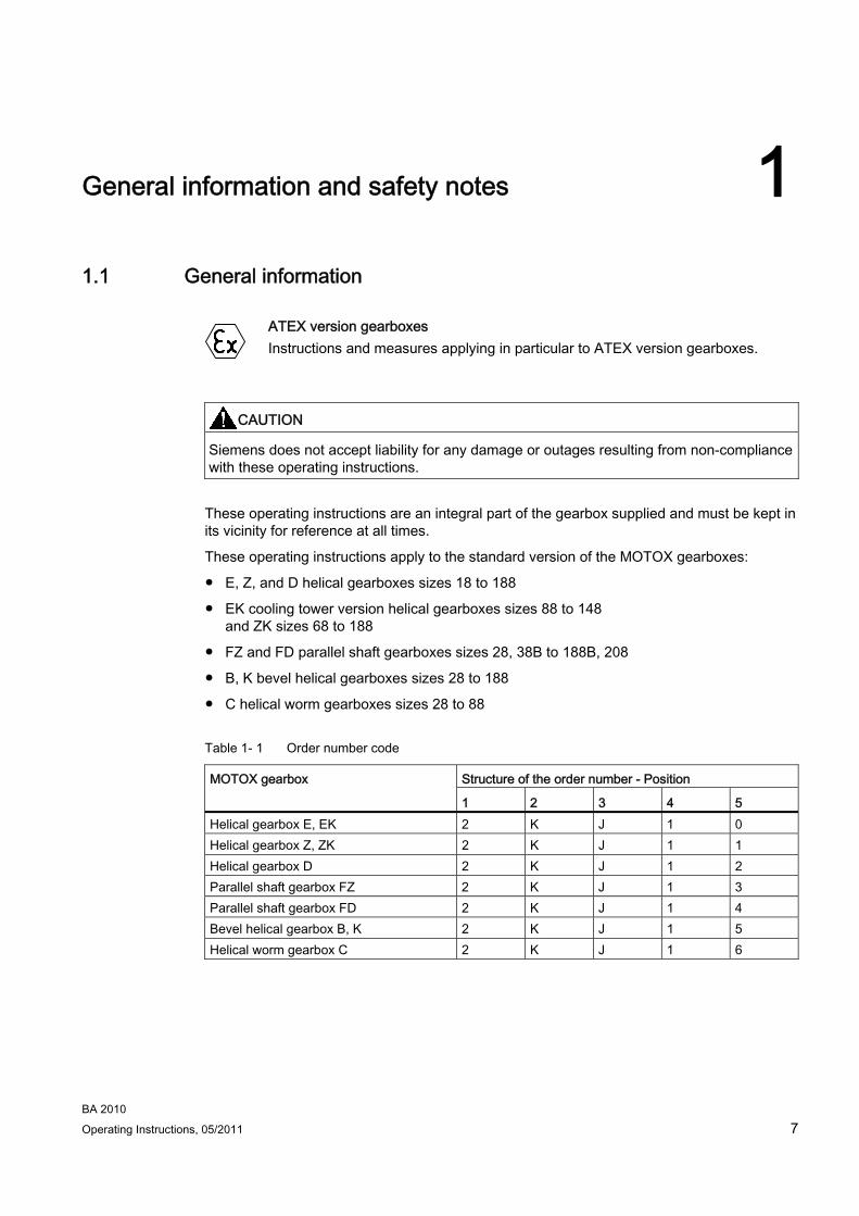
These operating instructions apply to the standard version of the MOTOX gearboxes:
● E, Z, and D helical gearboxes sizes 18 to 188
● EK cooling tower version helical gearboxes sizes 88 to 148 and ZK sizes 68 to 188
● FZ and FD parallel shaft gearboxes sizes 28, 38B to 188B, 208
● B, K bevel helical gearboxes sizes 28 to 188
● C helical worm gearboxes sizes 28 to 88
Table 1- 1 Order number code
Structure of the order number - Position MOTOX gearbox
1 2 3 4 5 Helical gearbox E, EK 2 K J 1 0 Helical gearbox Z, ZK 2 K J 1 1 Helical gearbox D 2 K J 1 2 Parallel shaft gearbox FZ 2 K J 1 3 Parallel shaft gearbox FD 2 K J 1 4 Bevel helical gearbox B, K 2 K J 1 5 Helical worm gearbox C 2 K J 1 6
BA 2010 Operating Instructions, 05/2011 7
General information and safety notes 1.1 General information
BA 2010 8 Operating Instructions, 05/2011
Note
In addition to these operating instructions, special contractual agreements and technical documentation apply to these special gearbox designs and the associated supplementary equipment.
Please refer to the other operating instructions supplied with the product.
The gearboxes described here correspond to the state of the art at the time these operating instructions were printed.
In the interest of technical progress we reserve the right to make changes to the individual assemblies and accessories which we regard as necessary to preserve their essential characteristics and improve their efficiency and safety.
If you have any technical questions, please contact Technical Support.
Europe - Germany Phone: +49 (0) 911 895 7222 Fax: +49 (0) 911 895 7223
America - USA Phone: +1 42 32 62 25 22
Asia - China Phone: +86 10 64 75 75 75
Email: [email protected]
Internet German: http://www.siemens.de/automation/support-request
Internet English: http://www.siemens.com/automation/support-request
General information and safety notes 1.2 Copyright
BA 2010 Operating Instructions, 05/2011 9
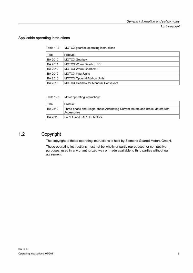
Applicable operating instructions
Table 1- 2 MOTOX gearbox operating instructions
Title Product BA 2010 MOTOX Gearbox BA 2011 MOTOX Worm Gearbox SC BA 2012 MOTOX Worm Gearbox S BA 2019 MOTOX Input Units BA 2510 MOTOX Optional Add-on Units BA 2515 MOTOX Gearbox for Monorail Conveyors
Table 1- 3 Motor operating instructions
Title Product BA 2310 Three-phase and Single-phase Alternating Current Motors and Brake Motors with
Accessories BA 2320 LA / LG and LAI / LGI Motors
1.2 Copyright The copyright to these operating instructions is held by Siemens Geared Motors GmbH.
These operating instructions must not be wholly or partly reproduced for competitive purposes, used in any unauthorized way or made available to third parties without our agreement.

General information and safety notes 1.3 Intended use
BA 2010 10 Operating Instructions, 05/2011
1.3 Intended use
ATEX version gearboxes
The ATEX gearbox meets the requirements of the Explosion Protection Directive 94/9/EC. In the case of ATEX version gearboxes, please observe instructions marked with this symbol.
The MOTOX gearboxes described in these operating instructions have been designed for stationary use in general engineering applications.
Unless otherwise agreed, the gearboxes have been designed for use in plants and equipment in industrial environments.
The gearboxes have been built using state-of-the-art technology and are shipped in an operationally reliable condition. Changes made by users could affect this operational reliability and are forbidden.
Note
The performance data assumes an ambient temperature of -20 °C to +40 °C and an installation altitude of up to 5,000 m above sea level.
In the case of other ambient temperatures and installation altitudes, please contact Technical Support.
The gearboxes have been designed solely for the application described in Technical data (Page 79). Do not operate the gearboxes outside the specified power limits. Other operating conditions must be contractually agreed.
Do not stand or walk on the gearboxes.
General information and safety notes 1.4 Obligations of the user
BA 2010 Operating Instructions, 05/2011 11
1.4 Obligations of the user The operator must ensure that all persons assigned to work on the gearbox have read and understood these operating instructions and that they follow them in all points in order to:
● Eliminate the risk to life and limb of users and others
● Ensure the safety and reliability of the gearbox
● Avoid disruptions and environmental damage through incorrect use.
Note the following safety information:
Shut down the geared motors and disconnect the power before you carry out any work on them.
Make sure that the drive unit cannot be turned on accidentally, e.g. lock the key-operated switch. Place a warning notice at the drive connection point which clearly indicates that work is in progress on the geared motor.
Carry out all work with great care and with due regard to safety.
Ensure compliance with the relevant safety and environmental regulations during transport, mounting and dismantling, operation, and care and maintenance of the unit.
Read the instructions on the rating plates attached to the geared motor. The rating plates must be kept free from paint and dirt at all times. Replace any missing rating plates.
In the event of changes during operation, immediately switch off the drive unit.
Take appropriate protective measures to prevent accidental contact with rotating drive parts, such as couplings, gear wheels or belt drives.
Take appropriate measures to prevent accidental contact with parts and equipment that heat up to over +70 °C during operation.
When removing protective equipment, keep fasteners in a safe place. Re-attach removed protective equipment before commissioning.
Collect and dispose of used oil in accordance with regulations. Remove oil spillages immediately with an oil-binding agent in compliance with environmental requirements.
Do not carry out any welding work on the gearbox. Do not use the gearbox as a grounding point for welding operations.
Carry out equipotential bonding in accordance with applicable regulations and directives. Such work must be carried out by qualified electrical personnel only.
Do not use high-pressure cleaning equipment or sharp-edged tools to clean the gearbox.
Replace damaged screws with new screws of the same type and strength class.
We can only accept liability for original spare parts supplied by Siemens Geared Motors GmbH.
If the geared motor is being installed in a plant or equipment, the manufacturers of such plant or equipment must ensure that the contents of these operating instructions are incorporated into their own instructions, information, and descriptions.
General information and safety notes 1.5 Particular type of risk and personal protective equipment
BA 2010 12 Operating Instructions, 05/2011
1.5 Particular type of risk and personal protective equipment
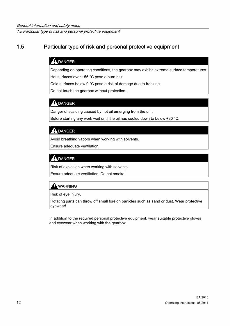
DANGER Depending on operating conditions, the gearbox may exhibit extreme surface temperatures.
Hot surfaces over +55 °C pose a burn risk.
Cold surfaces below 0 °C pose a risk of damage due to freezing.
Do not touch the gearbox without protection.
DANGER Danger of scalding caused by hot oil emerging from the unit.
Before starting any work wait until the oil has cooled down to below +30 °C.
DANGER Avoid breathing vapors when working with solvents.
Ensure adequate ventilation.
DANGER Risk of explosion when working with solvents.
Ensure adequate ventilation. Do not smoke!
WARNING Risk of eye injury.
Rotating parts can throw off small foreign particles such as sand or dust. Wear protective eyewear!
In addition to the required personal protective equipment, wear suitable protective gloves and eyewear when working with the gearbox.
Technical description 22.1 General description
The gearbox is supplied with one, two or three transmission stages.
The gearbox is suitable for various mounting positions. Observe the correct oil level.
2.2 Housing The housings for sizes 18 and 28 are made of die-cast aluminum. The housings for sizes 38 to 208 are made of grey cast iron.
2.3 Geared components The geared components of the gearboxes are hardened. In the case of helical worm gearboxes the worm is hardened and ground, and the gear is manufactured from bronze. The bevel gear stage of the bevel helical gearbox is lapped in pairs.
2.4 Lubrication The geared components are supplied with adequate lubricant by means of dip lubrication.
2.5 Shaft bearings All shafts are mounted in roller bearings. The roller bearings are lubricated by means of dip lubrication or oil spray lubrication. Bearings that are not supplied with lubricant are closed and grease-lubricated.
BA 2010 Operating Instructions, 05/2011 13
Technical description 2.6 Shaft seals
BA 2010 14 Operating Instructions, 05/2011
2.6 Shaft seals The radial shaft sealing ring, combination shaft sealing ring, labyrinth seal, and slide ring seal at the shaft outlet prevent lubricant from escaping from the housing and impurities from entering it.
2.6.1 Radial shaft sealing ring The radial shaft sealing ring is used as the standard type of seal. It is provided with an additional dust lip to protect against contaminants from outside.
At higher ambient temperatures over +40 °C to +80 °C, shaft sealing rings of temperature-resistant material are used, subject to contractual agreement.
2.6.2 Combination shaft sealing ring (optional) The combination shaft sealing ring offers an improved oil seal, for example, additional sealing lips prevent the ingress of dirt. The separate sealing system prevents shaft shrinkage due to corrosion or dirt. The grease packing prevents the sealing lips from running dry.
When carrying out repairs, e.g., if the shaft has shrunk, you can replace the standard seal with a combination shaft sealing ring.
2.7 Cooling
CAUTION Dust deposits prevent heat radiation and cause high housing temperatures.
Keep the gearbox free from dirt and dust, etc.
The gearbox does not normally require additional cooling. The generously dimensioned housing surface is sufficient for dissipating heat losses where there is free convection. If the housing temperature exceeds a value of +80 °C, please contact Technical Support.

Technical description 2.8 Backstop
BA 2010 Operating Instructions, 05/2011 15
2.8 Backstop
ATEX version gearboxes
The drive speed in the table "Drive speed when using backstops" must be reached in continuous operation. Starting and stopping operations ≤ 20 starts / stops per hour are permissible.
CAUTION Drive speeds below 1,000 rpm or frequent starting and stopping operations (≥ 20 starts / stops per hour) will limit service life.
Do not use the same backstop for prolonged periods; replace backstops regularly.
CAUTION Damage or destruction of the backstop due to incorrect direction of rotation.
Do not run the motor against the backstop.
Note the directional arrow on the gearbox.
The gearbox can be fitted with a mechanical backstop. The backstop can be fitted either in the coupling lantern or in the 2nd stage of the bevel helical gearbox. It permits only the correct direction of rotation during operation. This is indicated by an arrow pointing in the corresponding direction.
The backstop is fitted with centrifugally operated sprags. When the gearbox is running in the specified direction, the inner ring and the cage with the sprags also rotate while the outer ring remains stationary.
Where the backstop is used in the coupling lantern, lifting of the sprags is ensured when the drive speed is above the speed listed in the table. The backstop is wear-free. It does not require maintenance.
Technical description 2.9 Rating plate
BA 2010 16 Operating Instructions, 05/2011
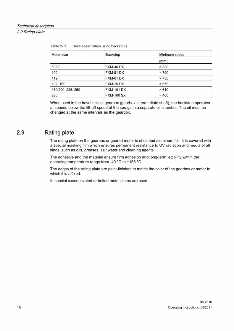
Table 2- 1 Drive speed when using backstops
Minimum speed Motor size Backstop
[rpm] 80/90 FXM-46 DX > 820 100 FXM-51 DX > 750 112 FXM-61 DX > 750 132, 160 FXM-76 DX > 670 180/200, 225, 250 FXM-101 DX > 610 280 FXM-100 SX > 400
When used in the bevel helical gearbox (gearbox intermediate shaft), the backstop operates at speeds below the lift-off speed of the sprags in a separate oil chamber. The oil must be changed at the same intervals as the gearbox.
2.9 Rating plate The rating plate on the gearbox or geared motor is of coated aluminum foil. It is covered with a special masking film which ensures permanent resistance to UV radiation and media of all kinds, such as oils, greases, salt water and cleaning agents.
The adhesive and the material ensure firm adhesion and long-term legibility within the operating temperature range from -40 °C to +155 °C.
The edges of the rating plate are paint-finished to match the color of the gearbox or motor to which it is affixed.
In special cases, riveted or bolted metal plates are used.

Technical description 2.10 Surface treatment
BA 2010 Operating Instructions, 05/2011 17
2.10 Surface treatment
2.10.1 General information on surface treatment All paint finishes are sprayed on.
ATEX version gearboxes
The gearbox is delivered complete with primer and paint finish. The conductivity requirement and the limit on the thickness of the applied coat of paint correspond to DIN EN 13463-1. The maximum permissible coat thickness results from explosion group IIA, IIB or IIC and according to the ignition energy. No electrostatic charge is expected for coating thicknesses below 200 μm.
ATEX version gearboxes
If the gearbox is delivered with primer only, a paint finish must be applied which meets the applicable guidelines for the specific application. The primer does not provide adequate corrosion protection. An excessively high electrostatic charge must be avoided. Ensure that highly active mechanisms that cause the paint finish to generate a charge are avoided. Highly active mechanisms of charge generation can be: fast air with high dust content directed past the gearbox
sudden escape of compressed gases containing particulates
harsh abrasive processes (not referring to manual cleaning / wiping with cleaning rags).
CAUTION Any damage to the paint finish will destroy the exterior protection and cause corrosion.
Do not damage the paint.
Note
Information about repaintability is not a guarantee of the quality of the paint product purchased from your supplier.
Only the paint manufacturer is liable for the quality and compatibility.
Technical description 2.10 Surface treatment
BA 2010 18 Operating Instructions, 05/2011
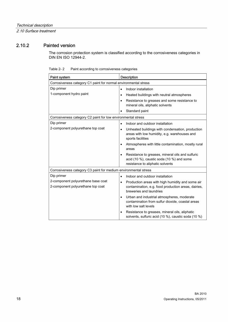
2.10.2 Painted version The corrosion protection system is classified according to the corrosiveness categories in DIN EN ISO 12944-2.
Table 2- 2 Paint according to corrosiveness categories
Paint system Description Corrosiveness category C1 paint for normal environmental stress Dip primer 1-component hydro paint
Indoor installation Heated buildings with neutral atmospheres Resistance to greases and some resistance to
mineral oils, aliphatic solvents Standard paint
Corrosiveness category C2 paint for low environmental stress Dip primer 2-component polyurethane top coat
Indoor and outdoor installation Unheated buildings with condensation, production
areas with low humidity, e.g. warehouses and sports facilities
Atmospheres with little contamination, mostly rural areas
Resistance to greases, mineral oils and sulfuric acid (10 %), caustic soda (10 %) and some resistance to aliphatic solvents
Corrosiveness category C3 paint for medium environmental stress Dip primer 2-component polyurethane base coat 2-component polyurethane top coat
Indoor and outdoor installation Production areas with high humidity and some air
contamination, e.g. food production areas, dairies, breweries and laundries
Urban and industrial atmospheres, moderate contamination from sulfur dioxide, coastal areas with low salt levels
Resistance to greases, mineral oils, aliphatic solvents, sulfuric acid (10 %), caustic soda (10 %)

Technical description 2.10 Surface treatment
BA 2010 Operating Instructions, 05/2011 19
Paint system Description Corrosiveness category C4 paint for high environmental stress Dip primer 2-component epoxy zinc phosphate 2-component polyurethane top coat
Indoor and outdoor installation Chemical plants, swimming pools, wastewater
treatment plants, electroplating shops, and boathouses above seawater
Industrial areas and coastal areas with moderate salt levels
Resistance to greases, mineral oils, aliphatic solvents, sulfuric acid (10 %), caustic soda (10 %)
Corrosiveness category C5 paint for very high environmental stress Dip primer 2-component epoxy zinc phosphate 2-component epoxy iron mica 2-component polyurethane top coat
Indoor and outdoor installation Buildings and areas with almost constant
condensation and high contamination, e.g. malt factories and aseptic areas
Industrial areas with high humidity and aggressive atmosphere, coastal areas and offshore environments with high salt levels
Resistance to greases, mineral oils, aliphatic solvents, sulfuric acid (10 %), caustic soda (10 %)
In case of corrosiveness category C1, can be overpainted with 1-component hydrosystem after prior rubbing down.
In case of corrosiveness category C2 to C5, can be overpainted with 2-component polyurethane paint, 2-component epoxide paint, and 2-component acrylic paint after prior rubbing down.

Technical description 2.10 Surface treatment
BA 2010 20 Operating Instructions, 05/2011
2.10.3 Primed version
Table 2- 3 Primer according to corrosiveness categories
Paint system Can be overpainted with Unpainted (corrosiveness category C1 G) Cast iron parts immersion primed, steel parts primed or zinc-plated, aluminum and plastic parts untreated
Plastic paint, synthetic resin paint, oil paint, 2-component polyurethane paint, 2-component epoxide paint
Primer according to corrosiveness category C2 G 2-component metal primer, desired coat thickness 60 μm
2-component polyurethane paint, 2-component epoxide paint and acid-hardening paint, 2-component acrylic paint
Primer according to corrosiveness category C4 G 2-component epoxide zinc phosphate, desired coat thickness 120 μm
2-component polyurethane paint, 2-component epoxide paint and acid-hardening paint, 2-component acrylic paint
On gearbox or geared motor versions which are primed or unpainted the rating plate and the masking film are covered with a paint-protective film. These facilitate repainting without further preparation, e.g. masking with adhesive tape.
Peeling off the paint-protective film
The paint coat must have fully hardened before the paint-protective film is peeled off (be at least "touch-proof").
① Company logo ② Masking film ③ Rating plate ④ Paint-protective film ⑤ Peeling tab
Figure 2-1 Rating plate with paint-protective film
Procedure 1. Pull the peeling tab ⑤ up.
2. Carefully peel the paint-protective film ④ off diagonally from one corner (not parallel to the plate).
3. Blow any paint fragments away or wipe them off with a clean cloth.
You have now removed the paint-protective film.
3Incoming goods, transport, and storage
3.1 Incoming goods
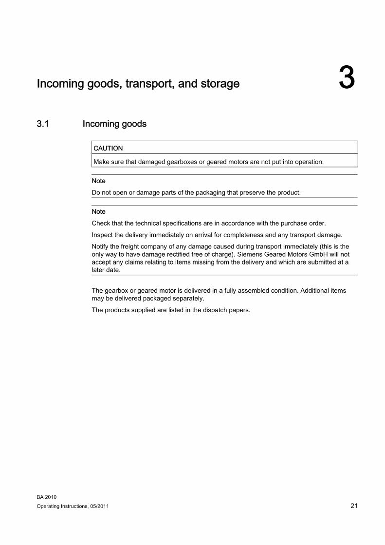
CAUTION Make sure that damaged gearboxes or geared motors are not put into operation.
Note
Do not open or damage parts of the packaging that preserve the product.
Note
Check that the technical specifications are in accordance with the purchase order.
Inspect the delivery immediately on arrival for completeness and any transport damage.
Notify the freight company of any damage caused during transport immediately (this is the only way to have damage rectified free of charge). Siemens Geared Motors GmbH will not accept any claims relating to items missing from the delivery and which are submitted at a later date.
The gearbox or geared motor is delivered in a fully assembled condition. Additional items may be delivered packaged separately.
The products supplied are listed in the dispatch papers.
BA 2010 Operating Instructions, 05/2011 21
Incoming goods, transport, and storage 3.2 Transport
BA 2010 22 Operating Instructions, 05/2011
3.2 Transport
3.2.1 General information on transport
CAUTION The use of force will damage the gearbox or geared motor.
Transport the gearbox or geared motor carefully. Avoid knocks.
Before putting the drive into operation, remove any transport fixtures and keep them safe or render them ineffective. For further transports reuse or reactivate them again.
Different forms of packaging may be used, depending on the size of the gearbox or geared motor and the method of transport. Notwithstanding contractual agreements to the contrary, the packaging complies with HPE Packaging Guidelines (Bundesverband Holzpackmittel Paletten Exportverpackungen e.V., the German Federal Association for wooden packaging means, pallets, and export packaging).
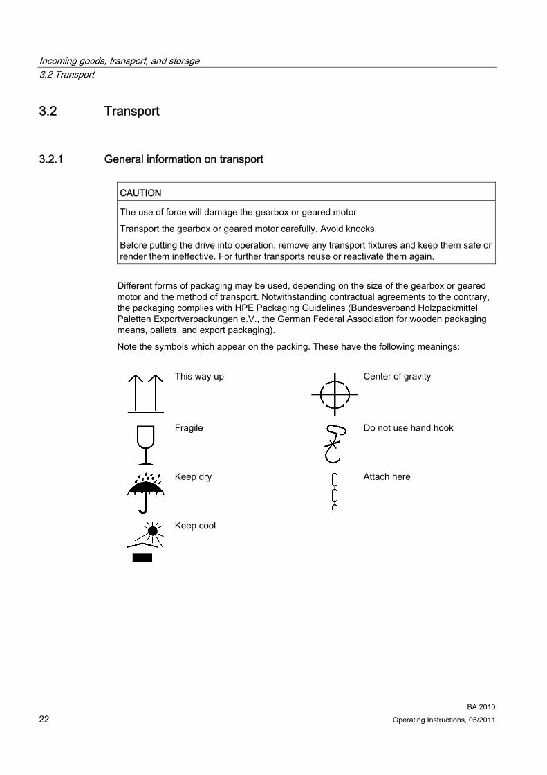
Note the symbols which appear on the packing. These have the following meanings:
This way up
Center of gravity
Fragile
Do not use hand hook
Keep dry
Attach here
Keep cool
Incoming goods, transport, and storage 3.2 Transport
BA 2010 Operating Instructions, 05/2011 23
3.2.2 Fastening for suspended transport
DANGER Gearboxes or geared motors may come loose and fall down during transport if not secured sufficiently.
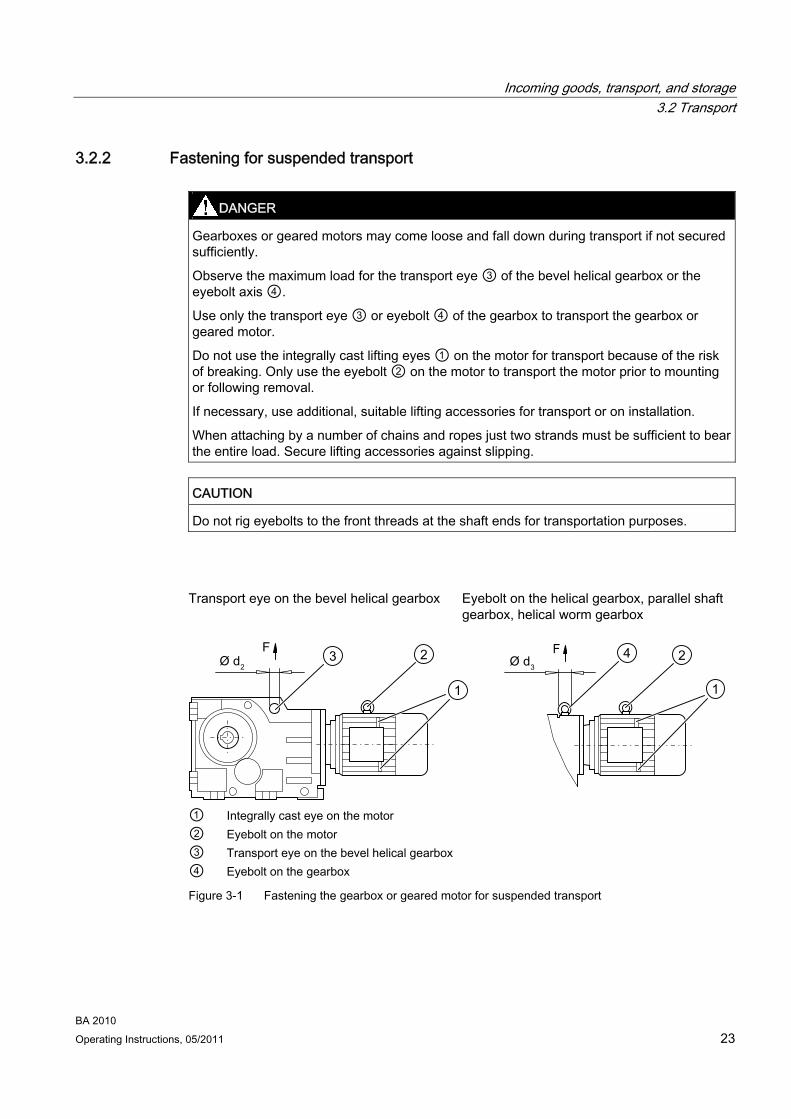
Observe the maximum load for the transport eye ③ of the bevel helical gearbox or the eyebolt axis ④.
Use only the transport eye ③ or eyebolt ④ of the gearbox to transport the gearbox or geared motor.
Do not use the integrally cast lifting eyes ① on the motor for transport because of the risk of breaking. Only use the eyebolt ② on the motor to transport the motor prior to mounting or following removal.
If necessary, use additional, suitable lifting accessories for transport or on installation.
When attaching by a number of chains and ropes just two strands must be sufficient to bear the entire load. Secure lifting accessories against slipping.
CAUTION Do not rig eyebolts to the front threads at the shaft ends for transportation purposes.
Transport eye on the bevel helical gearbox Eyebolt on the helical gearbox, parallel shaft
gearbox, helical worm gearbox
① Integrally cast eye on the motor ② Eyebolt on the motor ③ Transport eye on the bevel helical gearbox ④ Eyebolt on the gearbox
Figure 3-1 Fastening the gearbox or geared motor for suspended transport

Incoming goods, transport, and storage 3.2 Transport
BA 2010 24 Operating Instructions, 05/2011
The maximum load m in kg generated by the geared motor to be attached, with pull ↑ in direction F is listed in the following tables:
Table 3- 1 Maximum load of the transport eye on the bevel helical gearbox
m d2 m d2 Size
[kg] [mm]
Size
[kg] [mm] K.38 200 22 K.128 800 40 K.48 250 22 K.148 1,300 44 K.68 350 26 K.168 1,800 55 K.88 600 30 K.188 2,300 55 K.108 750 35
Table 3- 2 Maximum load of the eyebolt on the gearbox
m d3 m d3 Thread size
[kg] [mm]
Thread size
[kg] [mm] M8 140 36 M20 1,200 72 M10 230 45 M24 1,800 90 M12 340 54 M30 3,600 108 M16 700 63
Procedure 1. Mount the geared motor on the transport device by the heaviest permissible weight to be
attached. This will normally be on the main gearbox.
2. Check that the eyebolt is firmly seated.
The geared motor is slung for transport.

Incoming goods, transport, and storage 3.3 Storage
BA 2010 Operating Instructions, 05/2011 25
3.3 Storage
3.3.1 General information for storage
DANGER Do not stack gearboxes or geared motors one on top of another.
CAUTION Mechanical damage (scratches), chemical damage (acids, alkalis) and thermal damage (sparks, welding beads, heat) cause corrosion which may render the external protective coating ineffective.
Do not damage the paint.
Note
Notwithstanding contractual agreements to the contrary, the guarantee period for the standard preservative lasts 6 months from the date of delivery.
In the case of storage in transit over 6 months, special arrangements must be made for preservation. Please contact Technical Support.
3.3.2 Storage up to 6 months The gearbox or geared motor must be covered and stored in its position of use on a horizontal wooden support in a dry place not subject to significant temperature fluctuations. The storage location must be vibration- and shock-free.
The free shaft ends and flange surface are painted for protection.

Incoming goods, transport, and storage 3.3 Storage
BA 2010 26 Operating Instructions, 05/2011
3.3.3 Storage up to 36 months with long-term preservation (optional)
CAUTION The gearbox is completely filled with operating oil and closed airtight with a plug or by pressure venting with transport fixture.
Check the oil level before commissioning.
Store the gearbox or geared motor in dry, dust-free, and temperate locations. Special packing is then not necessary.
Otherwise, the gearbox or geared motor must be packed in plastic film or packed in airtight sealed film and water absorbing agents. Cover them to provide protection against sun and rain.
The storage location must be vibration- and shock-free.
The free shaft ends, sealing elements and flanges must be coated with a protective layer of grease.
The life of the corrosion protection is 36 months from delivery.
Do not reduce the oil level during short-time startup for 10 minutes in no-load operation.
Carry out the following precautionary measures after every period of 6 months in storage:
Table 3- 3 Preventive action
Storage period in months Action
6 12 18 24 30 36 Checking the insulation resistance - - x x x x Short-time startup: no-load operation, approximately 10 minutes at rated voltage
- - x x x x
Touch up / re-apply the protective layer of grease - - x x x x Check the cover and preservation x x x x x x

4Installation
4.1 Unpacking
CAUTION Make sure that damaged gearboxes or geared motors are not put into operation.
Check the gearbox or geared motor for completeness and for damage. Report any missing parts or damage immediately.
Remove packaging and transport fixtures and dispose of them properly.
4.2 General information on installation
ATEX version gearboxes
Effect on bearings of stray electric currents from electrical equipment. When mounting the gearbox on or connecting it to the machine, take care to ensure potential equalization.
WARNING The entire system must be load-free so that there is no danger during this work.
CAUTION Overheating of the gearbox due to exposure to direct sunlight.
Provide suitable protective equipment such as covers or roofs. Prevent heat accumulation.
CAUTION Malfunction resulting from foreign objects.
The operator must ensure that no foreign objects impair the function of the gearbox.
BA 2010 Operating Instructions, 05/2011 27

Installation 4.2 General information on installation
BA 2010 28 Operating Instructions, 05/2011
CAUTION Exceeding the permissible oil sump temperature due to incorrect settings of temperature monitoring equipment.
A warning must be given when the maximum permissible oil sump temperature is reached. The geared motor must be switched off when the maximum permissible oil sump temperature is exceeded. This switching off can cause plant shutdown.
CAUTION Irreparable damage to geared components and bearings due to welding.
Do not carry out any welding work on the gearbox. The gearbox must not be used as a grounding point for welding operations.
Note
Use headless screws of strength class 8.8 or higher to fasten the gearbox.
Exercise particular care during mounting and installation. The manufacturer cannot be held liable for damage caused by incorrect mounting and installation.
Make sure that there is sufficient space around the gearbox or geared motor for mounting, maintenance and repair.
On geared motors with a fan, leave sufficient free space for the entry of air. Observe the installation conditions for the geared motor.
Provide sufficient lifting gear at the start of mounting and fitting work.
Observe the type of construction specified on the rating plate. This ensures that the correct quantity of lubricant is provided.
Use all the fastening means which have been assigned to the relevant type of construction.
Cap screws cannot be used in some cases due to a lack of space. In such cases, please contact Technical Support quoting the type of gearbox.

Installation 4.3 Tightening torque for fastening bolts on the gearbox
BA 2010 Operating Instructions, 05/2011 29
4.3 Tightening torque for fastening bolts on the gearbox The general tolerance for the tightening torque in Nm is 10 %. The friction coefficient is 0.14 μ.
Table 4- 1 Tightening torques for fastening bolts
Tightening torque at strength class
8.8 10.9 12.9
Thread size
[Nm] [Nm] [Nm] M4 3 4 5 M5 6 9 10 M6 10 15 18 M8 25 35 41 M10 50 70 85 M12 90 120 145 M16 210 295 355 M20 450 580 690 M24 750 1 000 1 200 M30 1 500 2 000 2 400 M36 2 500 3 600 4 200
4.4 Fastening in the case of high shock loads In the case of high shock loads provide additional suitable positive fastenings such as cylindrical taper pins or spring pins.
CAUTION Do not use spring washers, serrated lock washers, spring or toothed lock washers, cup washers or conical spring washers as a substitute for the above positive fastenings.
Do not subject the housing to excessive stress when tightening the fastening bolts.

Installation 4.5 Gearbox with foot mounting
BA 2010 30 Operating Instructions, 05/2011
4.5 Gearbox with foot mounting
CAUTION Do not subject the gearbox to excessive stress when tightening the fastening bolts.
The foundation must be level and free from dirt.
The levelness deviation of the gearbox support must not exceed the following values:
For gearboxes up to size 88: 0.1 mm
For gearboxes from size 108: 0.2 mm
The foundation should be designed in such a way that no resonance vibrations are created and no vibrations are transmitted from adjacent foundations.
The foundation structure on which the gearbox is to be mounted must be rigid. They must be designed according to the weight and torque, taking into account the forces acting on the gearbox. If the substructure is too weak, it will cause radial or axial displacement, which cannot be measured at a standstill.
When using foundation blocks to fasten the gearbox to concrete foundations, suitable recesses should be made in the foundation.
Align and grout the slide rails into the foundation.
Align the gearbox carefully with the units on the input and output side. Take the elastic deformation due to operating forces into account.
Prevent displacement from external forces due to lateral impacts.
Use stud bolts or headless screws of strength class 8.8 or higher for the foot mounting. Observe the tightening torque.

Installation 4.6 Gearboxes in foot or flange version
BA 2010 Operating Instructions, 05/2011 31
4.6 Gearboxes in foot or flange version
CAUTION Do not subject gearbox housings to overstress from add-on elements on the foot or flange.
Add-on elements must not transmit forces, torques and vibration to the gearbox.
The gearbox must be fastened for force and torque transmission only to either the flange or the foot mounting to prevent overstress on the gearbox housing, see Gearbox with foot mounting (Page 30).
The second mounting option (foot or flange) is intended for add-on elements, e.g. protection covers with an intrinsic weight of up to max. 30 % of the weight of the gearbox.
4.7 Gearbox with C-type housing flange In the case of sizes 108 to 188, the customer's interface can be pinned on the C-type housing flange. The output flange has been designed to ensure the reliable transmission of the permissible torque and radial force by the bolt connections.
For additional fastening, e.g. in the case of high shock loads, the existing drilled pin holes can be used.
The gearboxes can also be drilled and pinned together with the machine. Compliance with the listed dimensions is mandatory in this case.
Installation 4.7 Gearbox with C-type housing flange
BA 2010 32 Operating Instructions, 05/2011
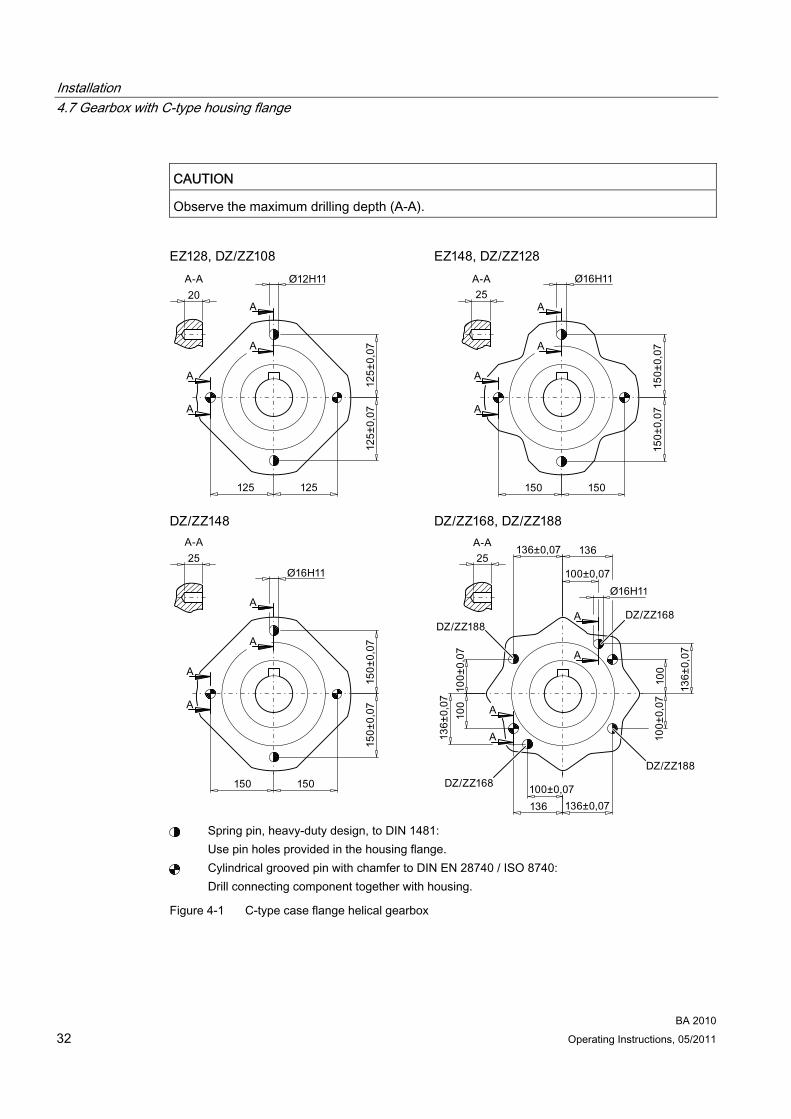
CAUTION Observe the maximum drilling depth (A-A).
Spring pin, heavy-duty design, to DIN 1481:
Use pin holes provided in the housing flange. Cylindrical grooved pin with chamfer to DIN EN 28740 / ISO 8740:
Drill connecting component together with housing.
Figure 4-1 C-type case flange helical gearbox
Installation 4.7 Gearbox with C-type housing flange
BA 2010 Operating Instructions, 05/2011 33
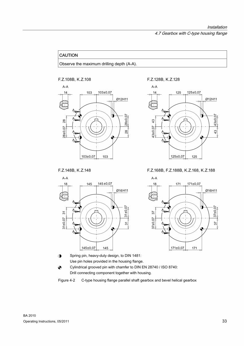
CAUTION Observe the maximum drilling depth (A-A).
Spring pin, heavy-duty design, to DIN 1481:
Use pin holes provided in the housing flange. Cylindrical grooved pin with chamfer to DIN EN 28740 / ISO 8740:
Drill connecting component together with housing.
Figure 4-2 C-type housing flange parallel shaft gearbox and bevel helical gearbox
Installation 4.8 Mounting the input or output element on the gearbox
BA 2010 34 Operating Instructions, 05/2011
4.8 Mounting the input or output element on the gearbox
DANGER Danger of burns due to hot parts.
Do not touch the gearbox without protection.
CAUTION Damage to shaft sealing rings caused by solvent or benzine.
Avoid contact at all times.
CAUTION Damage to shaft sealing rings caused by heating over 100 °C.
Protect shaft sealing rings from heating up due to radiant heat using thermal shields.
CAUTION Alignment errors caused by excessive angle or axial displacement of the shaft ends to be joined lead to premature wear or material damage.
Ensure precise alignment of the individual components.
CAUTION Damage to bearings, housing, shaft, and locking rings due to improper handling.
Do not use impacts or knocks to force the input and output elements to be mounted onto the shaft.
Note
Deburr the parts of elements to be fitted in the area of the hole or keyways.
Recommendation: 0.2 x 45°
Where couplings are to be fitted in a heated condition, observe the specific operating instructions for the coupling. Unless otherwise specified, the heat can be applied inductively, using a torch or in a furnace.
Use the centering holes in the shaft end faces.
Installation 4.8 Mounting the input or output element on the gearbox
BA 2010 Operating Instructions, 05/2011 35
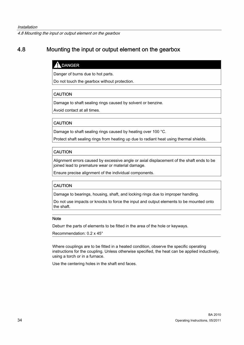
Use a fitting device to fit the input or output elements.
Figure 4-3 Example of a fitting device
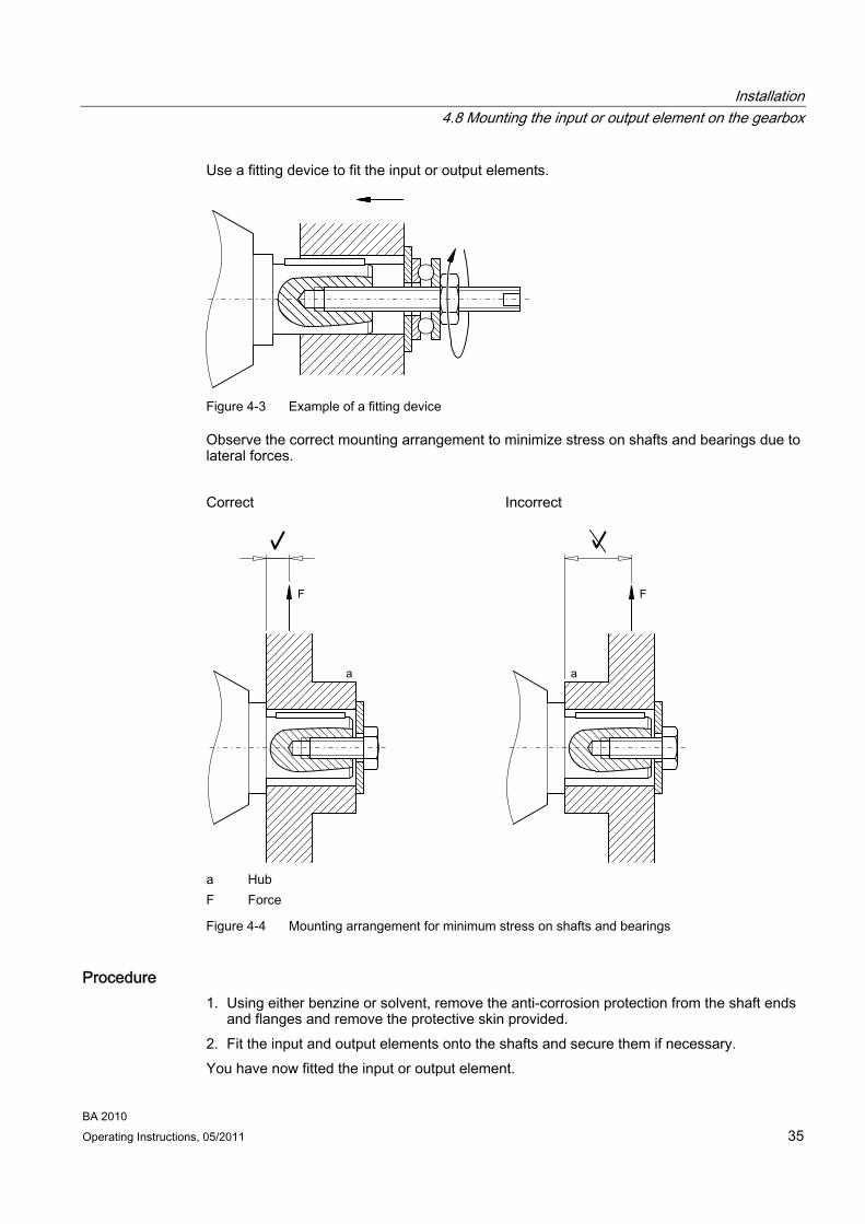
Observe the correct mounting arrangement to minimize stress on shafts and bearings due to lateral forces.
Correct Incorrect
a Hub F Force
Figure 4-4 Mounting arrangement for minimum stress on shafts and bearings
Procedure 1. Using either benzine or solvent, remove the anti-corrosion protection from the shaft ends
and flanges and remove the protective skin provided. 2. Fit the input and output elements onto the shafts and secure them if necessary. You have now fitted the input or output element.
Installation 4.9 Removing and installing the protection cover
BA 2010 36 Operating Instructions, 05/2011
4.9 Removing and installing the protection cover
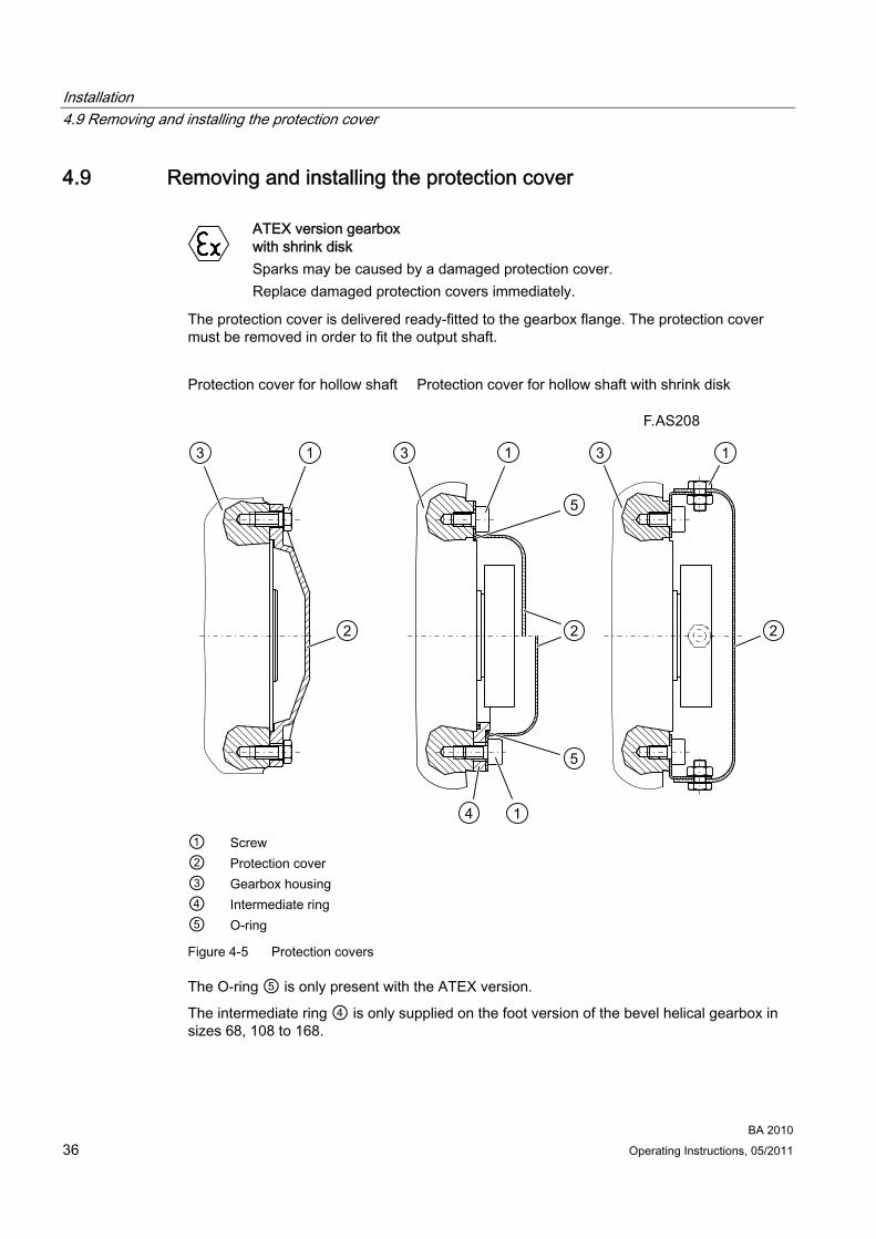
ATEX version gearbox with shrink disk Sparks may be caused by a damaged protection cover. Replace damaged protection covers immediately.
The protection cover is delivered ready-fitted to the gearbox flange. The protection cover must be removed in order to fit the output shaft.
Protection cover for hollow shaft Protection cover for hollow shaft with shrink disk
① Screw ② Protection cover ③ Gearbox housing ④ Intermediate ring ⑤ O-ring
Figure 4-5 Protection covers
The O-ring ⑤ is only present with the ATEX version.
The intermediate ring ④ is only supplied on the foot version of the bevel helical gearbox in sizes 68, 108 to 168.
Installation 4.9 Removing and installing the protection cover
BA 2010 Operating Instructions, 05/2011 37
Procedure 1. Undo the screws ① and remove the protection cover ②.
2. Fit the output shaft.
3. Using a suitable cleaning agent, clean the support surface of the protection cover ② on the gearbox.
4. With the protection cover for shrink disk in the ATEX version, ensure that the O-ring ⑤ is correctly seated.
5. Coat the supporting surface of the protection cover ② with a suitable sealing agent.
6. Screw on the protection cover ②.
7. Protect all remaining bare areas with a suitable permanent anti-corrosive agent.
You have now installed the protection cover for operation.

Installation 4.10 Removing and installing the shaft-mounted gearbox
BA 2010 38 Operating Instructions, 05/2011
4.10 Removing and installing the shaft-mounted gearbox
4.10.1 General information on installing the shaft-mounted gearbox
CAUTION Damage to shaft sealing rings caused by solvent or benzine.
Avoid contact at all times.
CAUTION Misalignment of and stress on the hollow shaft can lead to increased load and cause the bearings to fail.
The hollow shaft must be flush with the machine shaft to avoid misalignment.
Do not subject the hollow shaft to axial and radial stress.
CAUTION Shrink disks:
Lubricants in the area between the hollow shaft and machine shaft impair torque transmission.
Keep the bore in the hollow shaft and the machine shaft completely grease-free.
Do not use impure solvents and soiled cleaning cloths.
Note
Coat the contact surfaces with the mounting paste supplied with the product or any suitable lubricant to prevent frictional corrosion.
Note
Observe the permissible concentricity tolerance of the cylindrical shaft end of the machine shaft to the housing axle according to DIN 42955.

Installation 4.10 Removing and installing the shaft-mounted gearbox
BA 2010 Operating Instructions, 05/2011 39
4.10.2 Removing and installing the hollow shaft
4.10.2.1 Mounting the hollow shaft
Figure 4-6 Installing the hollow shaft with parallel key
Figure 4-7 Installing the hollow shaft with splines
a Greased b Absolutely grease-free
Figure 4-8 Installing the hollow shaft with shrink disk
* Not included in scope of supply

Installation 4.10 Removing and installing the shaft-mounted gearbox
BA 2010 40 Operating Instructions, 05/2011
① Machine shaft
② Hollow shaft
③ Hexagon nut
④ Threaded spindle
⑤ Disk
⑥ Locking ring
⑦ Parallel key
⑧ Bronze bush
Instead of the nut and threaded spindle shown in the diagram, other types of equipment such as hydraulic lifting equipment may be used.
Procedure 1. Using benzine or a solvent, remove the anti-corrosion protection from the shaft ends and
flanges.
2. Check the seats or edges of the hollow and machine shafts for damage. Please contact Technical Support if you notice any damage.
3. Fit the gearbox using a disk ⑤, threaded spindle ④ and nut ③. The counterforce is provided by the hollow shaft ②.
4. For hollow shaft with parallel key and hollow shaft with splines: Replace the nut ③ and threaded spindle ④ with a setscrew and tighten it with the specified torque. For hollow shaft with shrink disk: Remove the disk ⑤, threaded spindle ④ and nut ③.
You have now installed the hollow shaft.
Table 4- 2 Tightening torque for setscrews
Thread size M5 M6 M8 M10 M12 M16 M20 M24 M30 Tightening torque [Nm] 5 8 8 14 24 60 120 200 400

Installation 4.10 Removing and installing the shaft-mounted gearbox
BA 2010 Operating Instructions, 05/2011 41
4.10.2.2 Removing the hollow shaft with parallel key
CAUTION Before driving out the machine shaft, fasten a suitably dimensioned means of absorbing load to the gearbox.
Slightly pretension the drive element so that the gearbox does not drop into the drive element when the insert shaft is released.
CAUTION It is essential to prevent misalignment when removing the unit.
Note
If frictional corrosion has occurred on the seat surfaces, use rust solvent to facilitate the removal of the gearbox. Allow the rust solvent to work in sufficiently.
① Disk ② Threaded block ③ Parallel key ④ Hexagon nut ⑤ Threaded spindle
Figure 4-9 Removing the hollow shaft with parallel key
Item ① to ⑤ are not included in the scope of supply.
Procedure 1. Remove the axial fastening from the hollow shaft.
2. Drive out the machine shaft using the disk ①, threaded block ②, parallel key ③, threaded spindle ⑤ and hexagon nuts ④.
You have now removed the hollow shaft with parallel key.

Installation 4.10 Removing and installing the shaft-mounted gearbox
BA 2010 42 Operating Instructions, 05/2011
Design suggestion for threaded block and disk
b10 b11 b12 d10 d11 tmax u Size
[mm] [mm] [mm] [mm] [mm]
s11
[mm] [mm] 19.9 10 M6 22.5 6 28 3 15 10 24.9 14 M8 28 8
- - 14 M8 28 33
8 38 6
15 10 29.9 18 M10
38 10 34.9 24 10 48 6 15 5 39.9 28
M12 43 12
39.9 28 12 68 7 20 7 44.9 33
M16 48.5 14
49.9 36 14 88 7 20 10 59.9 45
M16 64 18
59.9 45 18 108 10 24 10 69.9 54
M20 74.5 20
69.9 54 20 128 10 24 5 79.9 62
M20 85 22
79.9 62 22 148 10 24 7 89.9 72
M20 95 25
99.9 80 106 168 10 30 8 M24 28 109.9 90 116
188 10 30 11 119.9 95 M24 127 32

Installation 4.10 Removing and installing the shaft-mounted gearbox
BA 2010 Operating Instructions, 05/2011 43
4.10.3 Shrink disk
4.10.3.1 Mounting the shrink disk
DANGER Risk of injury due to freely rotating parts.
Fit a cover cap or protection cover.
CAUTION The shrink disk is delivered ready for installation.
Do not dismantle the shrink disk before initial fitting.
CAUTION Lubricants in the area of the shrink disk seat impair torque transmission.
Keep the bore in the hollow shaft and the machine shaft completely grease-free.
Do not use impure solvents and soiled cleaning cloths.
CAUTION Plastic deformation of the hollow shaft when tightening the tightening bolts before fitting the machine shaft.
First fit machine shaft. Then tighten the tightening bolts.
CAUTION Avoid overloading the individual bolts.
Do not exceed the maximum tightening torque for tightening bolt.
Size 28: Tighten tightening bolts ③.
Sizes 38 - 208: The alignment of the end faces of outer ring ① and inner ring ② has priority. If this alignment is not achieved when tensioning, the tolerance of the insert shaft must be checked.

Installation 4.10 Removing and installing the shaft-mounted gearbox
BA 2010 44 Operating Instructions, 05/2011
Note
The hollow shaft is axially secured on the machine shaft by means of a shrink disk connection.
Note
Apply a thin layer of grease to the shrink disk seat on the hollow shaft.
Note
Coat with a suitable lubricant to prevent frictional corrosion of the contact surface on the customer's machine shaft in the vicinity of the bronze bush.
Size 28, 208 reinforced Sizes 38 - 208
a Greased b Absolutely grease-free ① Outer ring ② Inner ring ③ Tightening bolt ④ Hollow shaft ⑤ Machine shaft
Figure 4-10 Mounting the shrink disk

Installation 4.10 Removing and installing the shaft-mounted gearbox
BA 2010 Operating Instructions, 05/2011 45
Procedure 1. Tighten the tightening bolts ③ handtight initially.
2. Working round several times, evenly tighten the tightening bolts ③ by a ¼ turn each time (not crosswise).
3. Fit the rubber cover cap or protection cover included in the scope of delivery, see Removing and installing the protection cover (Page 36).
You have now installed the shrink disk.
Table 4- 3 Tightening torque for tightening bolt
Tightening torque Gearbox size Thread size Strength class
[Nm] 28 M5 8.8 5 38, 48, 68 M8 12.9 35 88, 108, 128 M10 12.9 70 148 M12 12.9 121 168, 188 M14 12.9 193
M16 12.9 295 208 M20 12.9 570
4.10.3.2 Pulling off the shrink disk 1. Working round several times, loosen the tightening bolts ③ one after the other, by a
¼ turn each time.
2. Pull the shrink disk off the hollow shaft.
Sizes 38 - 208: If the outer ring does not come away from the inner ring, remove some of the tightening bolts and insert them into neighboring forcing threads.
You will then be able to release the rings without difficulty.
4.10.3.3 Cleaning and lubricating shrink disks Soiled shrink disks must be cleaned and regreased prior to fitting.
Loosened shrink disks need not be dismantled and regreased before being retensioned.
Installation 4.10 Removing and installing the shaft-mounted gearbox
BA 2010 46 Operating Instructions, 05/2011
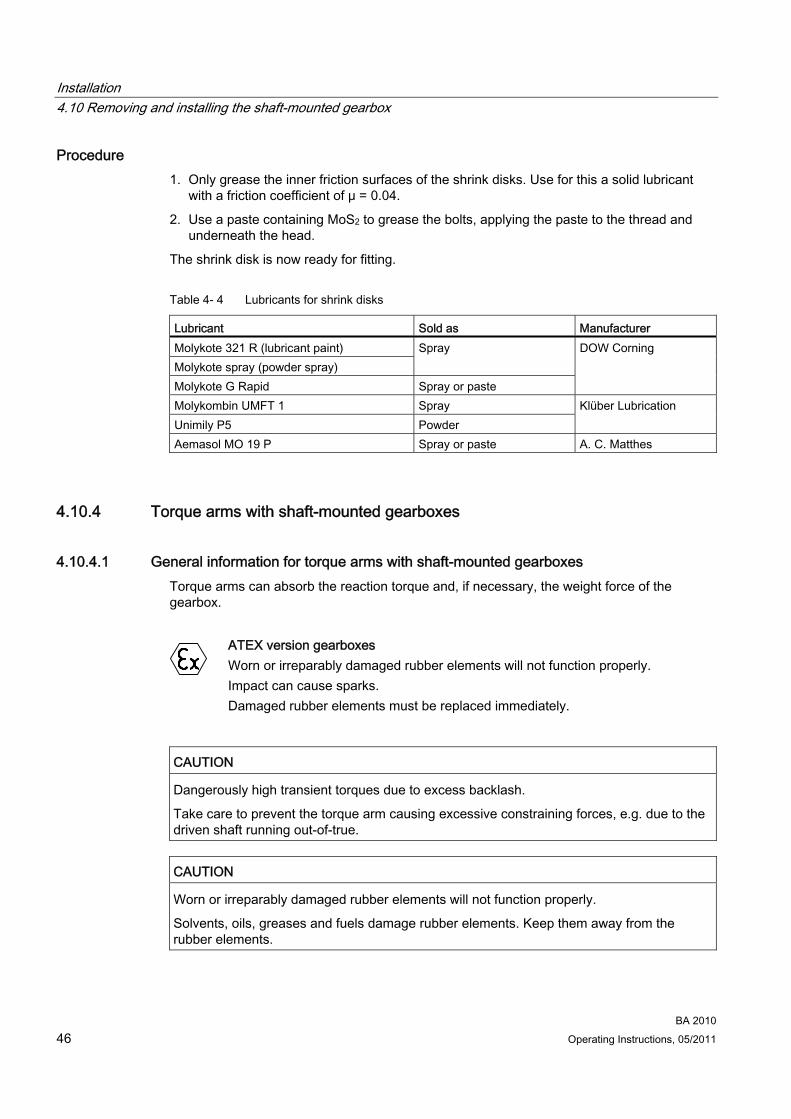
Procedure 1. Only grease the inner friction surfaces of the shrink disks. Use for this a solid lubricant
with a friction coefficient of μ = 0.04.
2. Use a paste containing MoS2 to grease the bolts, applying the paste to the thread and underneath the head.
The shrink disk is now ready for fitting.
Table 4- 4 Lubricants for shrink disks
Lubricant Sold as Manufacturer Molykote 321 R (lubricant paint) Molykote spray (powder spray)
Spray
Molykote G Rapid Spray or paste
DOW Corning
Molykombin UMFT 1 Spray Unimily P5 Powder
Klüber Lubrication
Aemasol MO 19 P Spray or paste A. C. Matthes
4.10.4 Torque arms with shaft-mounted gearboxes
4.10.4.1 General information for torque arms with shaft-mounted gearboxes Torque arms can absorb the reaction torque and, if necessary, the weight force of the gearbox.
ATEX version gearboxes
Worn or irreparably damaged rubber elements will not function properly. Impact can cause sparks. Damaged rubber elements must be replaced immediately.
CAUTION Dangerously high transient torques due to excess backlash.
Take care to prevent the torque arm causing excessive constraining forces, e.g. due to the driven shaft running out-of-true.
CAUTION Worn or irreparably damaged rubber elements will not function properly.
Solvents, oils, greases and fuels damage rubber elements. Keep them away from the rubber elements.
Installation 4.10 Removing and installing the shaft-mounted gearbox
BA 2010 Operating Instructions, 05/2011 47
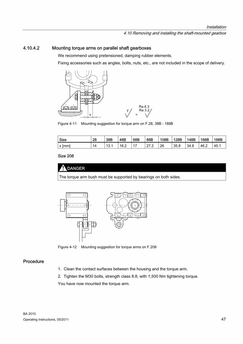
4.10.4.2 Mounting torque arms on parallel shaft gearboxes We recommend using pretensioned, damping rubber elements.
Fixing accessories such as angles, bolts, nuts, etc., are not included in the scope of delivery.
Figure 4-11 Mounting suggestion for torque arm on F.28, 38B - 188B
Size 28 38B 48B 68B 88B 108B 128B 148B 168B 188B x [mm] 14 13.1 18.2 17 27.2 26 35.8 34.8 46.2 45.1
Size 208
DANGER The torque arm bush must be supported by bearings on both sides.
Figure 4-12 Mounting suggestion for torque arms on F.208
Procedure 1. Clean the contact surfaces between the housing and the torque arm.
2. Tighten the M30 bolts, strength class 8.8, with 1,500 Nm tightening torque.
You have now mounted the torque arm.

Installation 4.10 Removing and installing the shaft-mounted gearbox
BA 2010 48 Operating Instructions, 05/2011
4.10.4.3 Mounting torque arms on bevel helical gearboxes and helical worm gearboxes
DANGER The torque arm bush must be supported by bearings on both sides.
Figure 4-13 Mounting suggestion for torque arm on foot
Figure 4-14 Mounting suggestion for torque arm on flange
The torque arm can be fitted in various positions, depending on the hole circle pitch.
Procedure 1. Clean the contact surfaces between the housing and the torque arm.
2. Tighten the bolts with the specified torque.
You have now mounted the torque arm.
Table 4- 5 Tightening torque for bolt of strength class 8.8 if torque arm is mounted
Thread size M8 M10 M12 M16 M20 M24 M30 Tightening torque [Nm] 25 50 90 210 450 750 1,500

5Commissioning
5.1 General information for commissioning
WARNING Secure the drive unit to prevent it from being started up unintentionally.
Attach a warning notice to the start switch.
WARNING Remove any oil spillage immediately with an oil-binding agent in compliance with environmental requirements.
CAUTION On cylindrical-roller bearings in the input unit, undershooting the minimum radial force can damage bearings.
Prolonged test runs when off-load must be kept to a minimum.
5.2 Checking the oil level prior to commissioning Check the oil level before commissioning and correct it if necessary, see Checking and changing lubricants (Page 59).
Gearboxes with long-term preservation are delivered with a full tank of oil. We recommend a complete oil change if your unit is left in storage for more than 24 months, see Checking and changing lubricants (Page 59).
5.3 Fitting the gearbox ventilation
5.3.1 Screwing in the vent filter or pressure breather valve without securing clip In the case of gearboxes with housing ventilation, the necessary vent filter or pressure breather valve without a securing clip is delivered separately. They must be replaced with the appropriate vent plug before starting up the gearbox.
BA 2010 Operating Instructions, 05/2011 49
Commissioning 5.4 Gearbox with backstop (optional)
BA 2010 50 Operating Instructions, 05/2011
Observe the symbol in the type of construction diagrams, see Types of construction (Page 85):
Ventilation
Procedure 1. Unscrew the vent plug.
2. Seal the gearbox with the vent filter or the pressure breather valve without securing clip.
You have now replaced the vent filter or pressure breather valve with the vent plug without the securing clip.
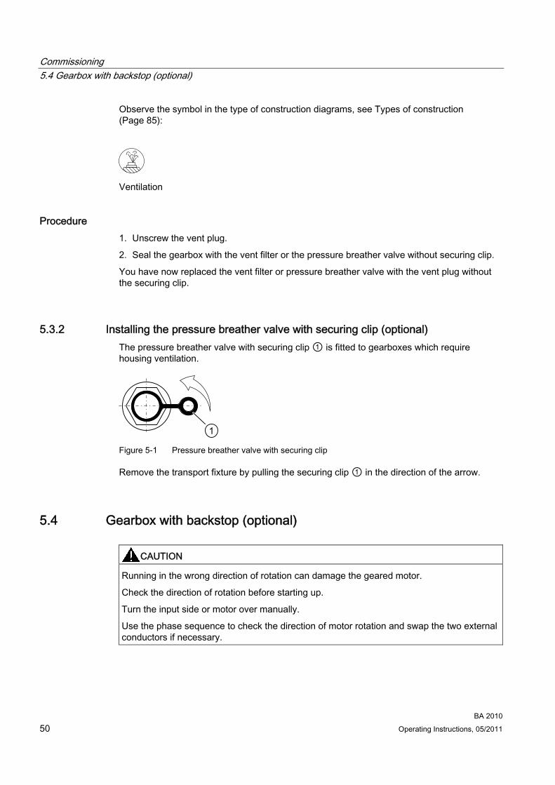
5.3.2 Installing the pressure breather valve with securing clip (optional) The pressure breather valve with securing clip ① is fitted to gearboxes which require housing ventilation.
Figure 5-1 Pressure breather valve with securing clip
Remove the transport fixture by pulling the securing clip ① in the direction of the arrow.
5.4 Gearbox with backstop (optional)
CAUTION Running in the wrong direction of rotation can damage the geared motor.
Check the direction of rotation before starting up.
Turn the input side or motor over manually.
Use the phase sequence to check the direction of motor rotation and swap the two external conductors if necessary.

6Operation
ATEX version gearboxes
The difference between the temperature of the housing and the ambient temperature of max. +40 °C must not exceed 70 K. Using a suitable temperature sensor, measure the temperature at the lowest point of the housing (oil sump) or at the mounting surface in the case of output units. Changes are an indication of possible incipient damage.
CAUTION In the event of changes during operation, the drive unit must be switched off immediately.
Use the fault table in the section titled "Faults, causes, and remedies" to determine the cause of the fault.
Remedy faults or have faults remedied.
CAUTION On cylindrical-roller bearings in the input unit, undershooting the minimum radial force can damage bearings.
Prolonged test runs when off-load must be kept to a minimum.
Check the gearbox during operation for:
● Excessive operating temperature
● Changes in gear noise
● Possible oil leakage at the housing and shaft seals.
BA 2010 Operating Instructions, 05/2011 51

Operation
BA 2010 52 Operating Instructions, 05/2011
7Faults, causes and remedies
Note
Faults and malfunctions occurring during the warranty period and requiring repair work on the gearbox must be remedied only by Technical Support. In the case of faults and malfunctions occurring after the warranty period, the cause of which cannot be precisely identified, we advise our customers to contact our Technical Support.
If you need the help of our Technical Support, please provide the following information: Data on the rating plate Nature and extent of the fault Suspected cause.
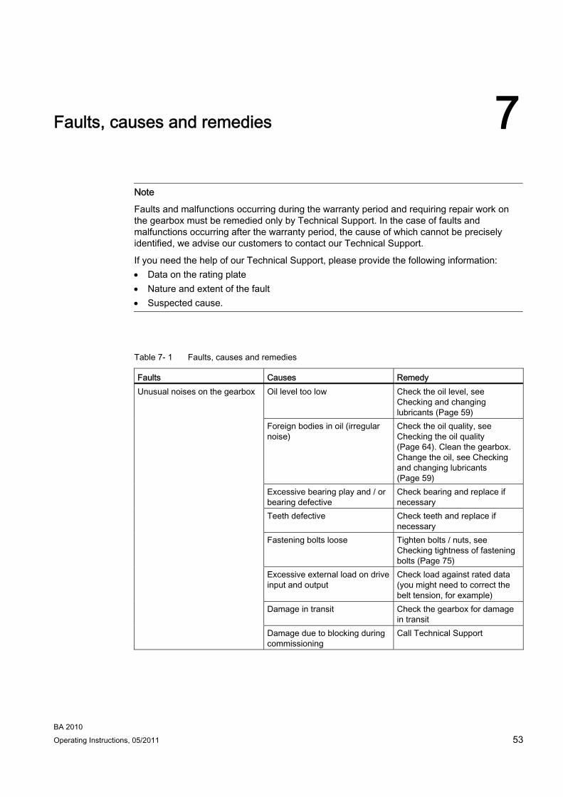
Table 7- 1 Faults, causes and remedies
Faults Causes Remedy Oil level too low Check the oil level, see
Checking and changing lubricants (Page 59)
Unusual noises on the gearbox
Foreign bodies in oil (irregular noise)
Check the oil quality, see Checking the oil quality (Page 64). Clean the gearbox. Change the oil, see Checking and changing lubricants (Page 59)
Excessive bearing play and / or bearing defective
Check bearing and replace if necessary
Teeth defective Check teeth and replace if necessary
Fastening bolts loose Tighten bolts / nuts, see Checking tightness of fastening bolts (Page 75)
Excessive external load on drive input and output
Check load against rated data (you might need to correct the belt tension, for example)
Damage in transit Check the gearbox for damage in transit
Damage due to blocking during commissioning
Call Technical Support
BA 2010 Operating Instructions, 05/2011 53

Faults, causes and remedies
BA 2010 54 Operating Instructions, 05/2011
Faults Causes Remedy Drive unit bearing not lubricated (motor size 160 and higher)
Regrease the bearing, see Changing the roller bearing grease (Page 69)
Excessive bearing play and / or bearing defective
Check bearing and replace if necessary
Unusual noises from drive unit
Fastening bolts loose Tighten bolts / nuts, see Checking tightness of fastening bolts (Page 75)
Excessive bearing play and / or bearing defective
Check bearing and replace if necessary
Motor brake rubbing Check air gap and adjust if necessary
Unusual noises on the motor
Inverter parameterization Correct parameterization Incorrect oil level for type of construction used
Check type of construction, see Types of construction (Page 85). Check the oil level, see Checking and changing lubricants (Page 59)
Overpressure due to lack of ventilation
Mount the ventilation as appropriate for the type of construction, see Fitting the gearbox ventilation (Page 49).
Overpressure due to soiled ventilation
Clean the ventilation, see Cleaning the vent filter (Page 74)
Shaft sealing rings defective Replace the shaft sealing rings Cover / flange bolts loose Tighten the bolts / nuts, see
Checking tightness of fastening bolts (Page 75). Continue to monitor the gearbox
Surface sealing defective (e.g., on cover, flange)
Reseal
Oil leak
Damage in transit (e.g., hairline cracks)
Check the gearbox for damage in transit
Faults, causes and remedies
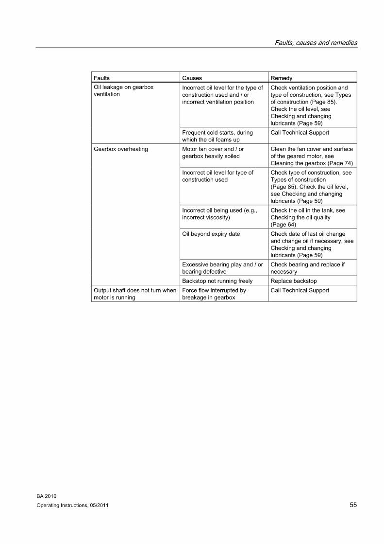
BA 2010 Operating Instructions, 05/2011 55
Faults Causes Remedy Incorrect oil level for the type of construction used and / or incorrect ventilation position
Check ventilation position and type of construction, see Types of construction (Page 85). Check the oil level, see Checking and changing lubricants (Page 59)
Oil leakage on gearbox ventilation
Frequent cold starts, during which the oil foams up
Call Technical Support
Motor fan cover and / or gearbox heavily soiled
Clean the fan cover and surface of the geared motor, see Cleaning the gearbox (Page 74)
Incorrect oil level for type of construction used
Check type of construction, see Types of construction (Page 85). Check the oil level, see Checking and changing lubricants (Page 59)
Incorrect oil being used (e.g., incorrect viscosity)
Check the oil in the tank, see Checking the oil quality (Page 64)
Oil beyond expiry date Check date of last oil change and change oil if necessary, see Checking and changing lubricants (Page 59)
Excessive bearing play and / or bearing defective
Check bearing and replace if necessary
Gearbox overheating
Backstop not running freely Replace backstop Output shaft does not turn when motor is running
Force flow interrupted by breakage in gearbox
Call Technical Support
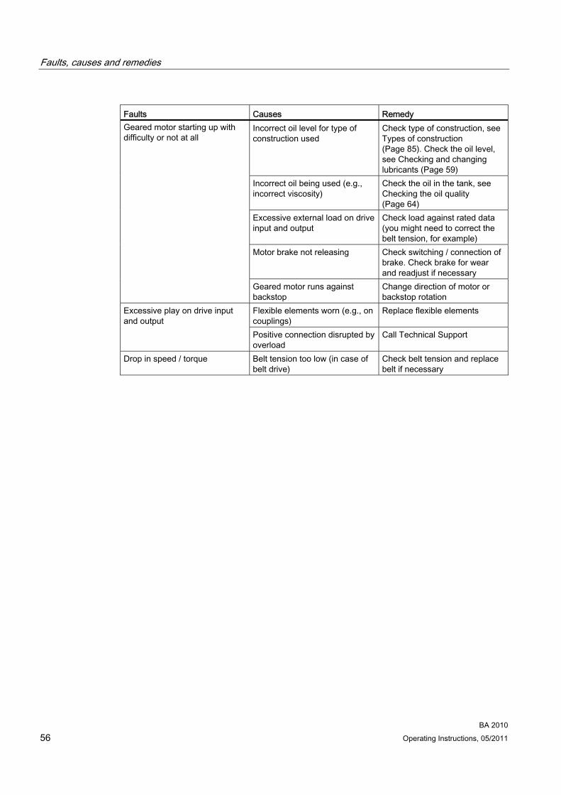
Faults, causes and remedies
BA 2010 56 Operating Instructions, 05/2011
Faults Causes Remedy Incorrect oil level for type of construction used
Check type of construction, see Types of construction (Page 85). Check the oil level, see Checking and changing lubricants (Page 59)
Incorrect oil being used (e.g., incorrect viscosity)
Check the oil in the tank, see Checking the oil quality (Page 64)
Excessive external load on drive input and output
Check load against rated data (you might need to correct the belt tension, for example)
Motor brake not releasing Check switching / connection of brake. Check brake for wear and readjust if necessary
Geared motor starting up with difficulty or not at all
Geared motor runs against backstop
Change direction of motor or backstop rotation
Flexible elements worn (e.g., on couplings)
Replace flexible elements Excessive play on drive input and output
Positive connection disrupted by overload
Call Technical Support
Drop in speed / torque Belt tension too low (in case of belt drive)
Check belt tension and replace belt if necessary
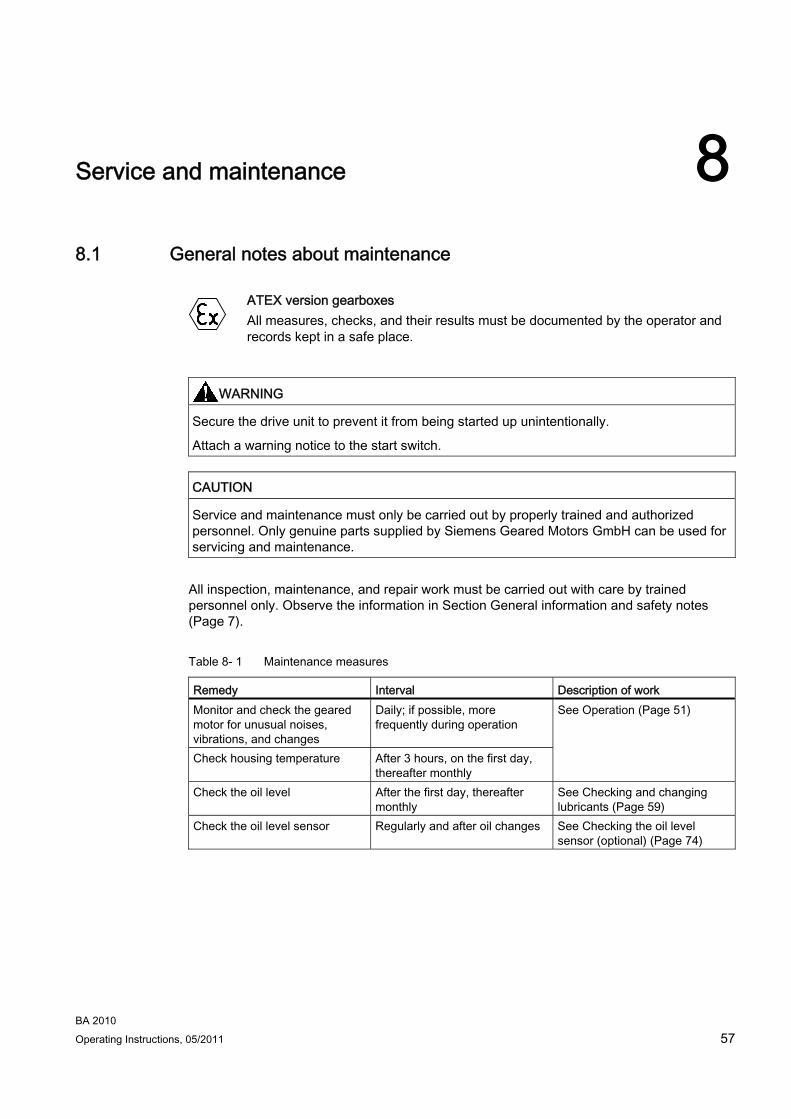
Service and maintenance 88.1 General notes about maintenance
ATEX version gearboxes
All measures, checks, and their results must be documented by the operator and records kept in a safe place.
WARNING Secure the drive unit to prevent it from being started up unintentionally.
Attach a warning notice to the start switch.
CAUTION Service and maintenance must only be carried out by properly trained and authorized personnel. Only genuine parts supplied by Siemens Geared Motors GmbH can be used for servicing and maintenance.
All inspection, maintenance, and repair work must be carried out with care by trained personnel only. Observe the information in Section General information and safety notes (Page 7).
Table 8- 1 Maintenance measures
Remedy Interval Description of work Monitor and check the geared motor for unusual noises, vibrations, and changes
Daily; if possible, more frequently during operation
See Operation (Page 51)
Check housing temperature After 3 hours, on the first day, thereafter monthly
Check the oil level After the first day, thereafter monthly
See Checking and changing lubricants (Page 59)
Check the oil level sensor Regularly and after oil changes See Checking the oil level sensor (optional) (Page 74)
BA 2010 Operating Instructions, 05/2011 57

Service and maintenance 8.1 General notes about maintenance
BA 2010 58 Operating Instructions, 05/2011
Remedy Interval Description of work Check the oil quality Every 6 months See Checking the oil quality
(Page 64) First oil change after commissioning
After approximately 10,000 operating hours or at the latest after 2 years
Subsequent oil changes Every 2 years or 10,000 operating hours 1)
See Checking and changing lubricants (Page 59)
Check gearbox for leaks After the first day, thereafter monthly
See Checking the gearbox for leaks (Page 73)
Clean the gearbox ventilation or replace if necessary
See Cleaning the vent filter (Page 74)
Clean the gearbox
Depending on degree of soiling, at least every 6 months
See Cleaning the gearbox (Page 74)
Check the friction clutch and adjust if necessary
After 500 hours, thereafter once a year and after every blockage
See Maintenance of the friction clutch (Page 76)
Check the coupling For the first time after 3 months Please refer to the separate operating instructions
Carry out a complete inspection of the geared motor
Every 12 months See Inspecting the gearbox or geared motor (Page 76)
Check that fastening bolts on gearboxes and built-on accessories are securely tightened. Check that covers and plugs are securely fastened
After 3 hours, regularly thereafter
See Checking tightness of fastening bolts (Page 75)
Change the roller bearing grease
When the oil is changed See Changing the roller bearing grease (Page 69)
Replace bearings - See Replacing bearings (Page 73)
Check rubber buffers on torque arms
Every 6 months See Torque arms with shaft-mounted gearboxes (Page 46)
1) When using synthetic oils, the intervals can be doubled. The data specified is valid for an oil temperature of +80 °C. See the figure titled "Guide values for oil change intervals" for oil change intervals for other temperatures.

Service and maintenance 8.2 Checking and changing lubricants
BA 2010 Operating Instructions, 05/2011 59
8.2 Checking and changing lubricants
8.2.1 General safety notes for checking and changing lubricants
DANGER After removing the oil level screw, up to and including gearbox size 128, the oil level may not be more than 3 mm and from gearbox size 148, not more than 5 mm below the recommended filling level.
DANGER Danger of scalding from the hot oil emerging from the unit.
Before starting any work wait until the oil has cooled down to below +30 °C.
WARNING Remove any oil spillage immediately with an oil-binding agent in compliance with environmental requirements.
CAUTION The oil quantity and the position of the sealing elements are determined by the type of construction.
Note
For data such as type of oil, oil viscosity, and oil quantity required, refer to the rating plate.
For oil compatibility see Recommended lubricants (Page 72).
Note
Gearbox sizes 18 and 28 are lubricated for life.
No oil changes are required.
Note
Where tandem gearboxes are concerned, each individual gearbox is to be considered separately.
Gearbox sizes 28 and 38 on the 2nd gearbox are lubricated for life. An oil change is not required.

Service and maintenance 8.2 Checking and changing lubricants
BA 2010 60 Operating Instructions, 05/2011
8.2.2 Checking the oil level
CAUTION The volume of gear oils changes with temperature.
If the temperature rises, the volume increases. Where temperature differences and filling quantities are significant, the increase can amount to several liters.
The oil level must therefore be checked while still slightly warm, approximately 30 minutes after switching off the drive unit.
Figure 8-1 Oil level in the gearbox housing
Procedure 1. Switch off the power supply to the drive unit.
2. Unscrew the oil level screw, see Types of construction (Page 85).
3. Check the oil level ①.
4. Rectify the oil level ① if necessary and check it again.
5. Check the condition of the sealing ring on the sealing element and replace the sealing ring if necessary.
6. Seal the gearbox with the sealing element.
You have now checked the oil level in the gearbox housing.
Checking the oil level on size 38 gearbox housings with no screw plug for checking the oil level
Size 38 gearboxes have no screw for checking the oil level. In some versions of the B38 and BF38 bevel helical gearbox, there is an additional screw plug so that the oil level can be checked as described above.

Service and maintenance 8.2 Checking and changing lubricants
BA 2010 Operating Instructions, 05/2011 61
① Dipstick ② Mark ③ Screw plug
Figure 8-2 Checking the oil level on size 38 gearbox
Procedure 1. Switch off the power supply to the drive unit.
2. Remove the geared motor and set it down as illustrated in the figure. The screw plug ③ must be on the top.
3. Remove the screw plug ③.
4. Make a mark ② on a suitable dipstick ①.
5. Insert the dipstick ① vertically into the opening until the mark ② is level with the surface of the gearbox.
6. Pull the dipstick ① out vertically.
7. Measure the distance "x" on the dipstick ①.
8. Compare the value "x" with the value for distance "x".
9. Rectify the oil level if necessary and check it again.
10. Check the condition of the sealing ring on the screw plug ③ and replace the sealing ring if necessary.
11. Seal the gearbox using the screw plug ③.
12. Mount the geared motor.
You have now checked the oil level in the size 38 gearbox housing.

Service and maintenance 8.2 Checking and changing lubricants
BA 2010 62 Operating Instructions, 05/2011
① Dipstick ② Mark
Figure 8-3 Distance "x"
Table 8- 2 Values for max. distance "x"
Distance "x" Gearbox type
[mm] B5
B14 V1 V18
V3 V19
E.38
44 24 18 Z.38 87 56 33 D.38 81 31 26 B3 B6 B7 B8 V5 V6 E38 43 37 37 31 23 19 Z38 93 83 83 83 75 32 D38 89 82 82 82 52 35 B3-00
H-01 B8-00 H-02
B7-00 H-03
B6-00 H-04
V5-00 H-05
V6-00 H6
B, BA, BAS, BAT38 126 74 30 89 95 112 K, KA, KAS, KAT38 64 35 21 52 40 46 B5-01
H-01 B5-03 H-02
B5-02 H-03
B5-00 H-04
V1-00 H-05
V3-00 H-06
B.38 126 74 30 89 95 112 K.38 66 40 20 54 45 50 FZ.38B 137 152 137 137 87 73 FD.38B 110 147 132 132 110 65

Service and maintenance 8.2 Checking and changing lubricants
BA 2010 Operating Instructions, 05/2011 63
8.2.3 Checking the oil level using the oil sight glass (optional) If you are using an oil sight glass to check the oil level ①, the oil must be visible in the center of the sight glass if the oil is cool. If the oil is hot, the oil level ① is above the center of the sight glass. The oil level ① of cold oil is below the center of the sight glass.
Figure 8-4 Oil level in the oil sight glass
Rectify the oil level ① if necessary and check it again.
8.2.4 Checking the oil level using the oil dipstick (optional) To measure the oil level, push the oil dipstick into the hole but do not screw it in.
The oil level must be between the lower and upper min.-max. marks on the oil dipstick.
If you are using the electric oil level monitoring system, the oil must be level with the upper max. mark on the oil dipstick.
Rectify the oil level if necessary and check it again.

Service and maintenance 8.2 Checking and changing lubricants
BA 2010 64 Operating Instructions, 05/2011
8.2.5 Checking the oil quality Signs of changes in the oil can be seen with the naked eye. Fresh oil is clear to the eye and has a typical smell and a specific product color. Clouding or a flocculent appearance indicates water and / or contamination. A dark or black color indicates residue, serious thermal decomposition or contamination.
Observe the symbols in the type of construction diagrams, see Types of construction (Page 85):
Ventilation Oil filling Oil level
Procedure 1. Allow the geared motor to run for a short time. Wear and contaminant particles are visible
in the oil shortly after shutting down.
2. Switch off the power supply to the drive unit.
3. Remove the sealing element at one of the points marked with the symbols listed above.
4. Remove some oil, using a suction pump and a flexible hose, for example.
5. Check the condition of the sealing ring on the sealing element and replace the sealing ring if necessary.
6. Seal the gearbox with the sealing element.
7. Check the oil for abnormalities. If you detect any abnormalities, change the oil immediately.
8. Check the oil level.
9. Rectify the oil level if necessary and check it again.
You have now checked the oil quality.

Service and maintenance 8.2 Checking and changing lubricants
BA 2010 Operating Instructions, 05/2011 65
8.2.6 Changing the oil
8.2.6.1 General safety notes for changing the oil
CAUTION An impermissible mixture of oils will lead to clouding, depositing, foam formation, changes to the viscosity or reduced protection against corrosion and wear.
When changing oil of the same type, the residual volume of oil in the gearbox should be kept as low as possible. Generally speaking, a small residual volume will cause no particular problems.
Gear oils of different types and by different manufacturers must not be mixed. Have the manufacturer confirm that the new oil is compatible with the remaining volume of used oil.
If changing very different types of oil or oils with very different additives, always flush out the gearbox with the new oil. When changing from mineral oil to polyglycol oil (PG) or vice versa, it is vital to flush the gearbox twice. All traces of old oil must be completely removed from the gearbox.
CAUTION Gear oils must never be mixed with other substances. Do not flush with paraffin or other solvents, as traces of these substances will always be left behind inside the gearbox.
Note
The oil must be warm. If it is too cold, it will flow too sluggishly to drain properly. If necessary, run the gearbox for 15 to 30 minutes to warm it up.

Service and maintenance 8.2 Checking and changing lubricants
BA 2010 66 Operating Instructions, 05/2011
8.2.6.2 Draining the oil Observe the symbols in the type of construction diagrams, see Types of construction (Page 85):
Ventilation Oil filling Oil level Oil drain
Procedure 1. Switch off the power supply to the drive unit.
2. Unscrew the vent plug.
3. Unscrew the oil level screw.
4. Place a suitable and sufficiently large receptacle underneath the oil drain plug.
5. Remove the oil drain plug and drain all the oil into the receptacle.
6. Check the condition of the sealing ring on the sealing element and replace the sealing ring if necessary.
7. Seal the gearbox using the sealing elements.
You have now drained the oil from the gearbox.
Draining the oil from B38 with no additional screw plug type V5-00/V1-00/H-05 and V6-00/V3-00/H-06
Procedure 1. Switch off the power supply to the drive unit.
2. Place a suitable and sufficiently large receptacle underneath the gearbox.
3. Unscrew the oil filler screw.
4. Using a length of hose, siphon off all the oil into the receptacle.
5. Check the condition of the sealing ring on the sealing element and replace the sealing ring if necessary.
6. Seal the gearbox with the sealing element.
Or:
1. Switch off the power supply to the drive unit.
2. Unscrew the cover
3. Drain all the oil into the receptacle.
4. Change the seal in the cover.
5. Seal the gearbox with the cover.
You have now drained the oil from the B38 gearbox.
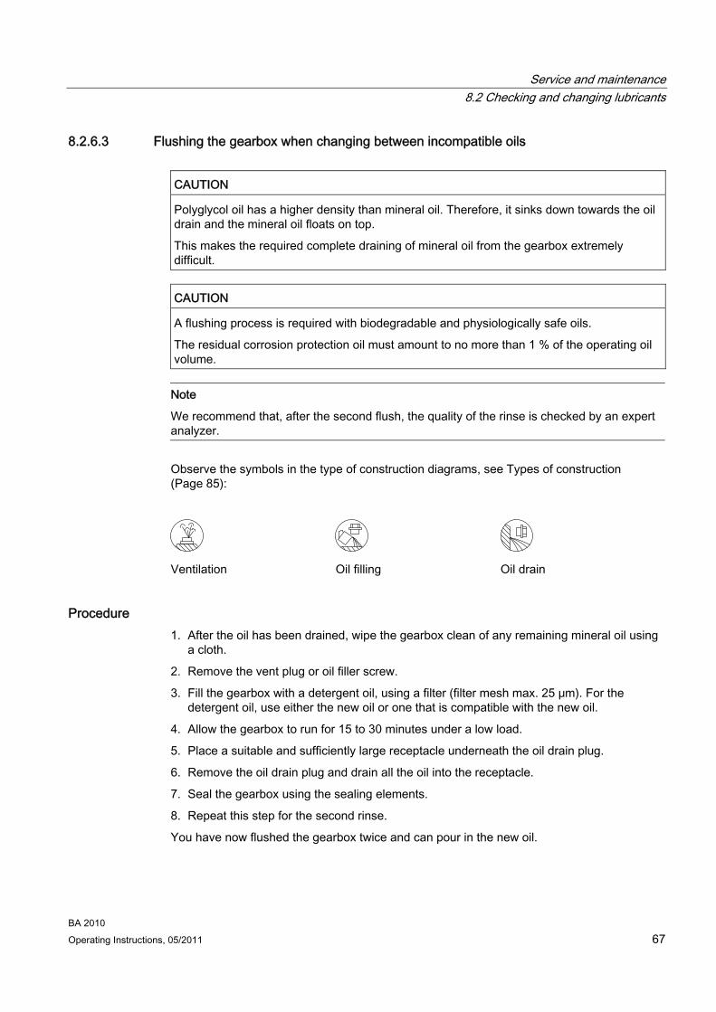
Service and maintenance 8.2 Checking and changing lubricants
BA 2010 Operating Instructions, 05/2011 67
8.2.6.3 Flushing the gearbox when changing between incompatible oils
CAUTION Polyglycol oil has a higher density than mineral oil. Therefore, it sinks down towards the oil drain and the mineral oil floats on top.
This makes the required complete draining of mineral oil from the gearbox extremely difficult.
CAUTION A flushing process is required with biodegradable and physiologically safe oils.
The residual corrosion protection oil must amount to no more than 1 % of the operating oil volume.
Note
We recommend that, after the second flush, the quality of the rinse is checked by an expert analyzer.
Observe the symbols in the type of construction diagrams, see Types of construction (Page 85):
Ventilation Oil filling Oil drain
Procedure 1. After the oil has been drained, wipe the gearbox clean of any remaining mineral oil using
a cloth.
2. Remove the vent plug or oil filler screw.
3. Fill the gearbox with a detergent oil, using a filter (filter mesh max. 25 μm). For the detergent oil, use either the new oil or one that is compatible with the new oil.
4. Allow the gearbox to run for 15 to 30 minutes under a low load.
5. Place a suitable and sufficiently large receptacle underneath the oil drain plug.
6. Remove the oil drain plug and drain all the oil into the receptacle.
7. Seal the gearbox using the sealing elements.
8. Repeat this step for the second rinse.
You have now flushed the gearbox twice and can pour in the new oil.
Service and maintenance 8.2 Checking and changing lubricants
BA 2010 68 Operating Instructions, 05/2011
8.2.6.4 Filling in oil Observe the symbols in the type of construction diagrams, see Types of construction (Page 85):
Ventilation Oil filling
Procedure 1. Remove the vent plug or oil filler screw.
2. Fill the gearbox with fresh oil, using a filter (filter mesh max. 25 μm). When refilling, use the same type of oil with the same viscosity. If changing mutually incompatible oils, flushing cycles are required, see Flushing the gearbox when changing between incompatible oils (Page 67).
3. Rectify the oil level if necessary and check it again.
4. Check the condition of the sealing ring on the sealing element and replace the sealing ring if necessary.
5. Seal the gearbox with the sealing element.
You have now filled up the gearbox with oil.
8.2.7 Topping up with oil You may need to top the gearbox up with oil if the gearbox type of construction changes or if oil is lost due to a leak. If you notice oil escaping, locate the leak and seal the affected area. Check and correct the oil level.
At the time of going to print, the following types of oil are being used for initial filing of the gearbox:
CLP ISO VG220: ARAL Degol BG 220
CLP ISO PG VG220: Castrol Tribol 800/220
CLP ISO PG VG460: Castrol Tribol 800/460
CLP ISO PAO VG68: Addinol Eco Gear 68S-T
CLP ISO PAO VG220: Addinol Eco Gear 220S
CLP ISO E VG220: Fuchs Plantogear Bio 220S
CLP ISO H1 VG460: Klüber Klüberoil 4 UH1 460 N
If, following agreement, gearboxes are filled at the factory with special lubricants for the special applications referred to above, this is shown on the rating plate.
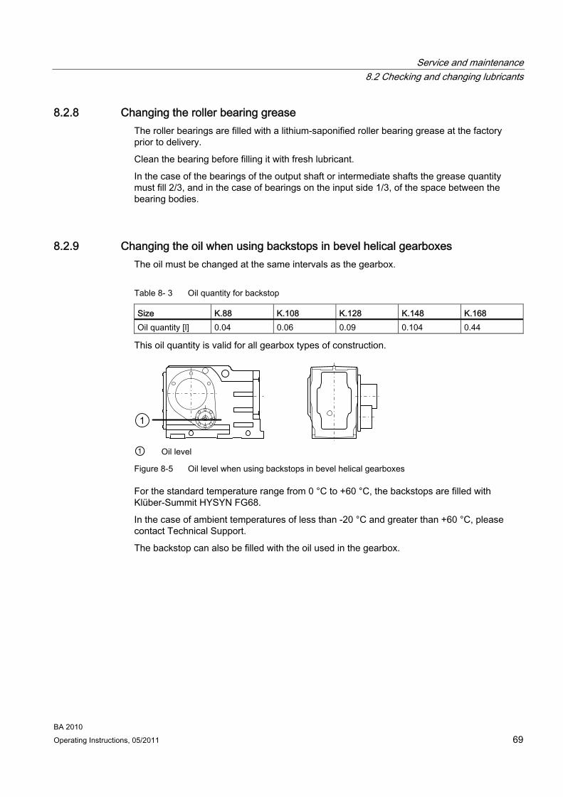
Service and maintenance 8.2 Checking and changing lubricants
BA 2010 Operating Instructions, 05/2011 69
8.2.8 Changing the roller bearing grease The roller bearings are filled with a lithium-saponified roller bearing grease at the factory prior to delivery.
Clean the bearing before filling it with fresh lubricant.
In the case of the bearings of the output shaft or intermediate shafts the grease quantity must fill 2/3, and in the case of bearings on the input side 1/3, of the space between the bearing bodies.
8.2.9 Changing the oil when using backstops in bevel helical gearboxes The oil must be changed at the same intervals as the gearbox.
Table 8- 3 Oil quantity for backstop
Size K.88 K.108 K.128 K.148 K.168 Oil quantity [l] 0.04 0.06 0.09 0.104 0.44
This oil quantity is valid for all gearbox types of construction.
① Oil level
Figure 8-5 Oil level when using backstops in bevel helical gearboxes
For the standard temperature range from 0 °C to +60 °C, the backstops are filled with Klüber-Summit HYSYN FG68.
In the case of ambient temperatures of less than -20 °C and greater than +60 °C, please contact Technical Support.
The backstop can also be filled with the oil used in the gearbox.

Service and maintenance 8.2 Checking and changing lubricants
BA 2010 70 Operating Instructions, 05/2011
8.2.10 Service life of the lubricants
Note
In case of ambient conditions deviating from normal conditions, e.g. high ambient temperatures, high relative humidity, aggressive ambient media, the intervals between changes should be shorter. In such cases please contact Technical Support for assistance in determining the individual lubricant change intervals.
Note
Oil sump temperatures above +80 °C can reduce service life. In this context, the rule is that increasing the temperature by 10 K will approximately halve the service life, as illustrated in the figure titled "Guide values for oil change intervals".
At an oil sump temperature of +80 °C, the following service life can be expected subject to compliance with the properties required by Siemens Geared Motors GmbH:
Table 8- 4 Service life of the oils
Type of oil Service life Mineral oil Biodegradable oil Physiologically safe oil according to USDA-H1/-H2
10,000 operating hours or 2 years
Synthetic oil 20,000 operating hours or 4 years

Service and maintenance 8.2 Checking and changing lubricants
BA 2010 Operating Instructions, 05/2011 71
① Mineral oil ② Synthetic oil T Oil-bath long-term temperature [°C] I Oil change interval in operating hours [h]
Figure 8-6 Guide values for oil change intervals
Grease service life of roller bearing greases
Roller bearings and the clearance in front are filled with sufficient grease.
Under approved operating conditions and ambient temperatures, no regreasing is required.
We recommend that the grease filling of the bearings is also changed when the oil or shaft sealing rings are replaced.

Service and maintenance 8.2 Checking and changing lubricants
BA 2010 72 Operating Instructions, 05/2011
8.2.11 Recommended lubricants
DANGER The lubricants used have not been approved to USDA -H1/-H2 (United States Department of Agriculture). They are not or only conditionally approved for use in the foodstuffs or pharmaceutical industry. If lubricants with USDA -H1/-H2 approval are required, please contact Technical Support.
CAUTION If you are working outside the temperature range specified in the Flender Operating Instructions BA 7300, please contact Technical Support for advice on which oil to use.
If the housing temperature exceeds a value of +80 °C, please contact Technical Support.
Note
The lubricants used are not or are only conditionally biodegradable. If lubricants classified as biodegradable are required, please contact Technical Support.
Note
These recommendations are not a guarantee of the quality of the lubricant provided by your supplier. All lubricant manufacturers are responsible for the quality of their own products.
The oil selected for use in the gearbox must be of the viscosity stated on the rating plate (ISO VG class). The viscosity class indicated applies for the contractually agreed operating conditions.
In the case of different operating conditions, please contact Technical Support.

Service and maintenance 8.3 Replacing bearings
BA 2010 Operating Instructions, 05/2011 73
The lubricants suitable for use in the gearbox are listed in the Operating Instructions BA 7300 "Gearbox Lubrication". We are familiar with the composition of these lubricants and, as far as we are currently aware, they possess state-of-the-art properties with regard to load-bearing capacity, corrosion resistance (FZG test DIN 51354 = force level > 12), resistance to gray staining and compatibility with seals and interior paint finishes as necessary for the type of gearbox concerned. Therefore, we advise our customers to select one of the lubricants listed in this table, taking into account the VG class specified on the rating plate.
If, following agreement, gearboxes are filled at the factory with special lubricants for the special applications referred to above, this is shown on the rating plate.
The warranty conditions are valid only for the lubricants listed in the Flender Operating Instructions BA 7300. If you decide to use a different oil, you are responsible for the technical suitability of the lubricant.
8.3 Replacing bearings
ATEX version gearboxes
Bearing life depends very much on operating conditions. It is, therefore, very difficult to calculate it reliably. In the operating conditions specified by the operator, bearing life can be calculated and indicated on the rating plate. If no information is given, changes in vibration and noise pattern can serve as an indicator that an immediate bearing replacement is necessary.
8.4 Checking the gearbox for leaks Oil or grease escaping in small quantities from the shaft sealing ring should be regarded as normal during the running-in phase of 24 hours running time.
If the quantities escaping are significant or leaking continues after the running-in phase, the shaft sealing ring must be replaced to prevent consequential damage.
Shaft sealing rings are subject to natural wear. Service life depends on operating conditions. We recommend that shaft sealing rings are included in periodic maintenance and servicing work on the system.
Service and maintenance 8.5 Cleaning the vent filter
BA 2010 74 Operating Instructions, 05/2011
8.5 Cleaning the vent filter Clean the vent filter at least every 6 months, or more regularly depending on the degree of soiling.
Procedure 1. Unscrew the vent filter.
2. Flush out the vent filter with benzine or a similar cleaning agent.
3. Blow the vent filter out with compressed air.
4. Seal the gearbox with the vent filter.
You have now cleaned the vent filter.
8.6 Checking the oil level sensor (optional)
ATEX version gearboxes
The oil level sensor indicates the oil level only when the gearbox is shut down. Lower the oil level and fill it up again until the oil level sensor gives a switching signal. Please refer to the separate operating instructions for the oil level sensor.
8.7 Cleaning the gearbox
CAUTION Dust deposits prevent heat radiation and cause high housing temperatures.
Keep the gearbox free from dirt and dust.
CAUTION Do not use a high-pressure cleaning appliance to clean the gearbox.
Do not use tools with sharp edges.
Switch off the power supply to the drive unit before cleaning it.
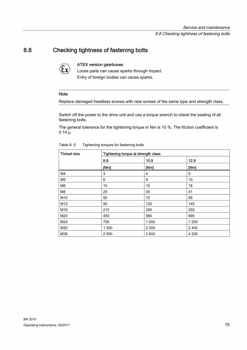
Service and maintenance 8.8 Checking tightness of fastening bolts
BA 2010 Operating Instructions, 05/2011 75
8.8 Checking tightness of fastening bolts
ATEX version gearboxes
Loose parts can cause sparks through impact. Entry of foreign bodies can cause sparks.
Note
Replace damaged headless screws with new screws of the same type and strength class.
Switch off the power to the drive unit and use a torque wrench to check the seating of all fastening bolts.
The general tolerance for the tightening torque in Nm is 10 %. The friction coefficient is 0.14 μ.
Table 8- 5 Tightening torques for fastening bolts
Tightening torque at strength class
8.8 10.9 12.9
Thread size
[Nm] [Nm] [Nm] M4 3 4 5 M5 6 9 10 M6 10 15 18 M8 25 35 41 M10 50 70 85 M12 90 120 145 M16 210 295 355 M20 450 580 690 M24 750 1 000 1 200 M30 1 500 2 000 2 400 M36 2 500 3 600 4 200

Service and maintenance 8.9 Inspecting the gearbox or geared motor
BA 2010 76 Operating Instructions, 05/2011
8.9 Inspecting the gearbox or geared motor Carry out a scheduled inspection of the geared motor once a year in accordance with the possible criteria listed in Section Auto-Hotspot.
Check the geared motor in accordance with the criteria set out in Section General information and safety notes (Page 7).
Touch up damaged paintwork carefully.
8.10 Maintenance of the friction clutch
Note
Check the condition of the friction clutch initially after 500 operating hours and then at least once yearly and after every blockage of the machine.
If necessary, readjust the friction torque or replace the wearing parts, e.g., friction lining and bushes. Friction linings must always be replaced in pairs. We recommend replacing worn bushes in sets.
Please refer to the relevant operating instructions for the clutch.

Disposal 9
DANGER Incorrect disposal of used oil is a threat to the environment and health.
After use, oil must be taken to a used oil collection point. The addition of foreign material such as solvents and brake and cooling fluid is prohibited.
Avoid prolonged contact with the skin.
Empty the used oil from the gearbox. The used oil must be collected, stored, transported and disposed of in accordance with regulations. Do not mix polyglycols with mineral oil. Polyglycols must be disposed of separately.
Please observe country-specific laws. Under German law, oils with different disposal codes may not be mixed with one another to allow optimal treatment of the oil (§4 VI Used Oil).
Collect and dispose of used oil in accordance with regulations.
Remove oil spillages immediately with an oil-binding agent in compliance with environmental requirements.
Dispose of the housing parts, gears, shafts, and roller bearings of the geared motor as steel scrap. The same applies to grey cast iron parts, if no separate collection is made.
The worm wheels are made partly from non-ferrous metal. Dispose of them accordingly.
Dispose of the packing material according to regulations or recycle it.
Table 9- 1 Disposal codes for gear oils
Type of oil Name Disposal code Mineral oil CLP ISO VG220 13 02 05 Polyglycols CLP ISO PG VG220
CLP ISO PG VG460 13 02 08
Polyalphaolefins CLP ISO PAO VG68 CLP ISO PAO VG220 CLP ISO H1 VG460
13 02 06
Biologically degradable oils CLP ISO E VG220 13 02 07
BA 2010 Operating Instructions, 05/2011 77

Disposal
BA 2010 78 Operating Instructions, 05/2011
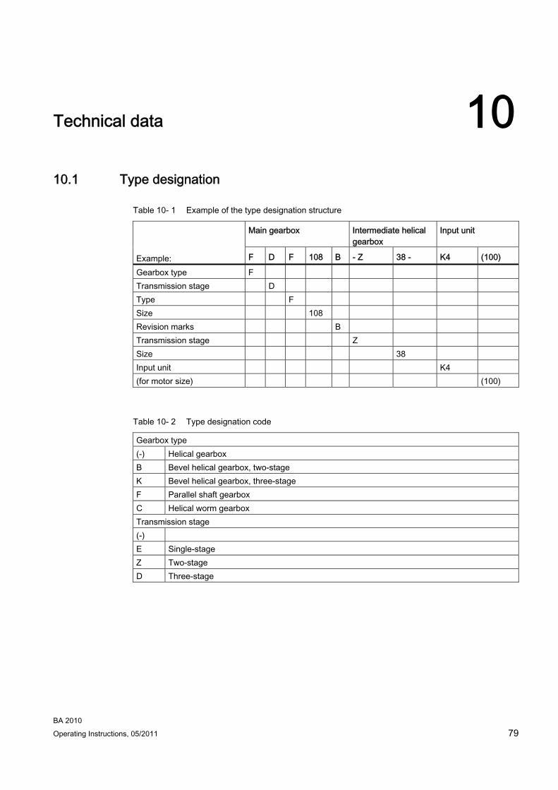
Technical data 1010.1 Type designation
Table 10- 1 Example of the type designation structure
Main gearbox Intermediate helical gearbox
Input unit
F D F 108 B - Z 38 - K4 (100) Example: Gearbox type F Transmission stage D Type F Size 108 Revision marks B Transmission stage Z Size 38 Input unit K4 (for motor size) (100)
Table 10- 2 Type designation code
Gearbox type (-) Helical gearbox B Bevel helical gearbox, two-stage K Bevel helical gearbox, three-stage F Parallel shaft gearbox C Helical worm gearbox Transmission stage (-) E Single-stage Z Two-stage D Three-stage
BA 2010 Operating Instructions, 05/2011 79

Technical data 10.1 Type designation
BA 2010 80 Operating Instructions, 05/2011
Type Shaft (-) Solid shaft A Hollow shaft Mounting (-) Foot-mounted version F Flange version (A type) Z Housing flange (C type) D Torque arm G Flange (A type) opposite output shaft R Agitator flange K Cooling tower version M Mixer flange E Extruder flange U Underwater version (slide ring seal) Connection (-) Parallel key S Shrink disk T Hollow shaft with splines Backstop
X Backstop in intermediate stage Intermediate helical gearbox Transmission stage Z Two-stage D Three-stage Input unit A / A5 Input unit with free input shaft K2 Coupling lantern with coupling for connecting an IEC motor K2TC Coupling lantern with coupling for connecting a NEMA motor K4 Short lantern with clamp connection for connecting an IEC motor K5TC Short coupling with clamp connection for connecting a NEMA motor KQ(S) Lantern for servo motor with zero-backlash coupling for connecting a servo motor P Input unit with free input shaft and piggy back for connecting an IEC motor P5 Input unit with free input shaft and piggy back for connecting a NEMA motor
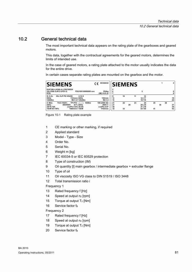
Technical data 10.2 General technical data
BA 2010 Operating Instructions, 05/2011 81
10.2 General technical data The most important technical data appears on the rating plate of the gearboxes and geared motors.
This data, together with the contractual agreements for the geared motors, determines the limits of intended use.
In the case of geared motors, a rating plate attached to the motor usually indicates the data for the entire drive.
In certain cases separate rating plates are mounted on the gearbox and the motor.
SIEMENSSIEMENS
13
273032
31 3835
25 2636 37
393433 40 41 42
28
1521 22 23 24
29
1416 19 20
3479 10 11 12
17 18
5 6
21
8
50Hz
50Hz29/16.74A15kW IE1-90%
cosPhi 0.84 28.6A60Hz
100Nm 190-240V AC460V Y
cosPhi 0.871460/min 15kW 1755/min
400/690V
1266Nm3~Mot. ThCl.155(F) TP-PTC
D/Y
113/minfB=1.5 1264Nm fB=1.5
KAF108-LA160L4-L150/100GH2KJ1506-5JR13-2FD1-ZIP55G. 6.2L OIL CLP PG VG220 i=12.9
60Hz 136/min
FDU1001/8999999 nnn 254kg
IEC60034
(IM) H-01-A
Figure 10-1 Rating plate example
1 CE marking or other marking, if required 2 Applied standard 3 Model - Type - Size 4 Order No. 5 Serial No. 6 Weight m [kg] 7 IEC 60034-5 or IEC 60529 protection 8 Type of construction (IM) 9 Oil quantity [l] main gearbox / intermediate gearbox + extruder flange 10 Type of oil 11 Oil viscosity ISO VG class to DIN 51519 / ISO 3448 12 Total transmission ratio i Frequency 1 13 Rated frequency f [Hz]
Speed at output n2 [rpm] 14 Torque at output T2 [Nm] 15 Service factor fB 16
Frequency 2 17 Rated frequency f [Hz]
Speed at output n2 [rpm] 18 Torque at output T2 [Nm] 19 Service factor fB 20

Technical data 10.2 General technical data
BA 2010 82 Operating Instructions, 05/2011
Motor data 21 Phase number and type of current for the motor 22 Temperature class Th.Cl. 23 Motor protection (TP)
Symbols (IEC 60617-2): = brake 24 Braking torque TBr [Nm] 25
26 Brake supply voltage U [V] Frequency 1 27 Rated frequency f [Hz] 28 Rated voltage / range U [V] 29 Circuit, graphical symbols as per DIN EN 60617 Part 6 / IEC 60617-6 30 Rated current I [A] 31 Power factor cos φ 32 Rated output P [kW], mode (if ≠ S1) 33 Efficiency class designation
Rated speed n1 [rpm] 34 Frequency 2 35 Rated frequency f [Hz] 36 Rated voltage / range U [V] 37 Rated current I [A] 38 Power factor cos φ 39 Circuit, graphical symbols as per DIN EN 60617 Part 6 / IEC 60617-6 40 Rated output P [kW], mode (if ≠ S1) 41 Efficiency class designation
Rated speed n1 [rpm] 42
Rating plate for ATEX version gearboxes
SIEMENS
131521
1416 19 20
3479 10 11 12
17 18
5 6
21
8
1 CE marking or other marking, if required 2 Applied standard 3 Model - Type - Size 4 Order No. 5 Serial No.
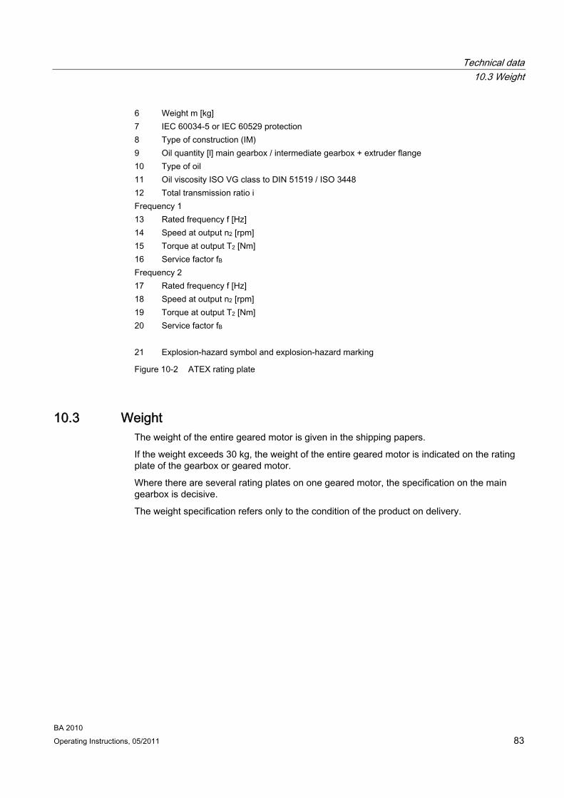
Technical data 10.3 Weight
BA 2010 Operating Instructions, 05/2011 83
6 Weight m [kg] 7 IEC 60034-5 or IEC 60529 protection 8 Type of construction (IM) 9 Oil quantity [l] main gearbox / intermediate gearbox + extruder flange 10 Type of oil 11 Oil viscosity ISO VG class to DIN 51519 / ISO 3448 12 Total transmission ratio i Frequency 1 13 Rated frequency f [Hz] 14 Speed at output n2 [rpm] 15 Torque at output T2 [Nm] 16 Service factor fB Frequency 2 17 Rated frequency f [Hz] 18 Speed at output n2 [rpm] 19 Torque at output T2 [Nm] 20 Service factor fB 21 Explosion-hazard symbol and explosion-hazard marking
Figure 10-2 ATEX rating plate
10.3 Weight The weight of the entire geared motor is given in the shipping papers.
If the weight exceeds 30 kg, the weight of the entire geared motor is indicated on the rating plate of the gearbox or geared motor.
Where there are several rating plates on one geared motor, the specification on the main gearbox is decisive.
The weight specification refers only to the condition of the product on delivery.

Technical data 10.4 Sound-pressure level
BA 2010 84 Operating Instructions, 05/2011
10.4 Sound-pressure level The A rated sound-pressure level LWA of a selection of gearboxes in the following figure has been measured to DIN EN ISO 1680 with meters to DIN IEC 60651.
The noise depends mainly on speed, output, and transmission ratio.
Figure 10-3 MOTOX geared motors sound-pressure level
The sound-pressure levels of MOTOX geared motors fall mainly in the dark-colored part of the range. Gearboxes with very small transmission ratios, high output, and high input speed may fall into the cross-hatched part.
If repeat measurements on site do not produce conclusive results which can be verified by measuring technology, the measurement obtained on the Siemens Geared Motors GmbH test benches will apply.
External noises
Noises not generated by the gearbox but emitted from it are not taken into consideration here.
Similarly, noises emitted from the input and output machines and from the foundation are not taken into consideration here, even if transmitted to these by the gearbox.

Technical data 10.5 Types of construction
BA 2010 Operating Instructions, 05/2011 85
10.5 Types of construction The type of construction designations are compliant with IEC 60034-7 (Code I).
The gearbox must be operated only in the type of construction specified on the rating plate. This ensures that the correct quantity of lubricant is provided.
Note
Gearbox sizes 18 and 28 are lubricated for life.
Screw plugs are not provided.
Explanation of symbols in type of construction diagrams:
Ventilation Oil filling Oil level Oil dipstick Oil drain
A, B Position of insert shaft / solid shaft V Gearboxes of size 38 are fitted as standard with a screw plug at point "V";
ventilation is not required. * On opposite side ② Two-stage gearbox
③ Three-stage gearbox
④ Tandem gearbox
⑤ Optional oil hole facing output side
- - - Alternatively

Technical data 10.5 Types of construction
BA 2010 86 Operating Instructions, 05/2011
10.5.1 Single-stage helical gearboxes
Figure 10-4 Type of construction options for E sizes 38 - 148
Figure 10-5 Type of construction options for E. sizes 38 - 148
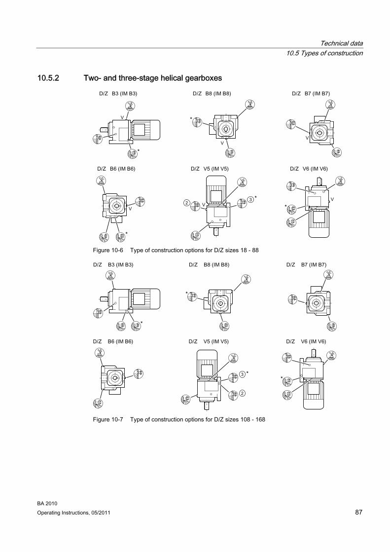
Technical data 10.5 Types of construction
BA 2010 Operating Instructions, 05/2011 87
10.5.2 Two- and three-stage helical gearboxes
Figure 10-6 Type of construction options for D/Z sizes 18 - 88
Figure 10-7 Type of construction options for D/Z sizes 108 - 168

Technical data 10.5 Types of construction
BA 2010 88 Operating Instructions, 05/2011
Figure 10-8 Type of construction options for D/Z188
Figure 10-9 Type of construction options for DF/ZF, DZ/ZZ sizes 18 - 88, DR/ZR sizes 68 - 88
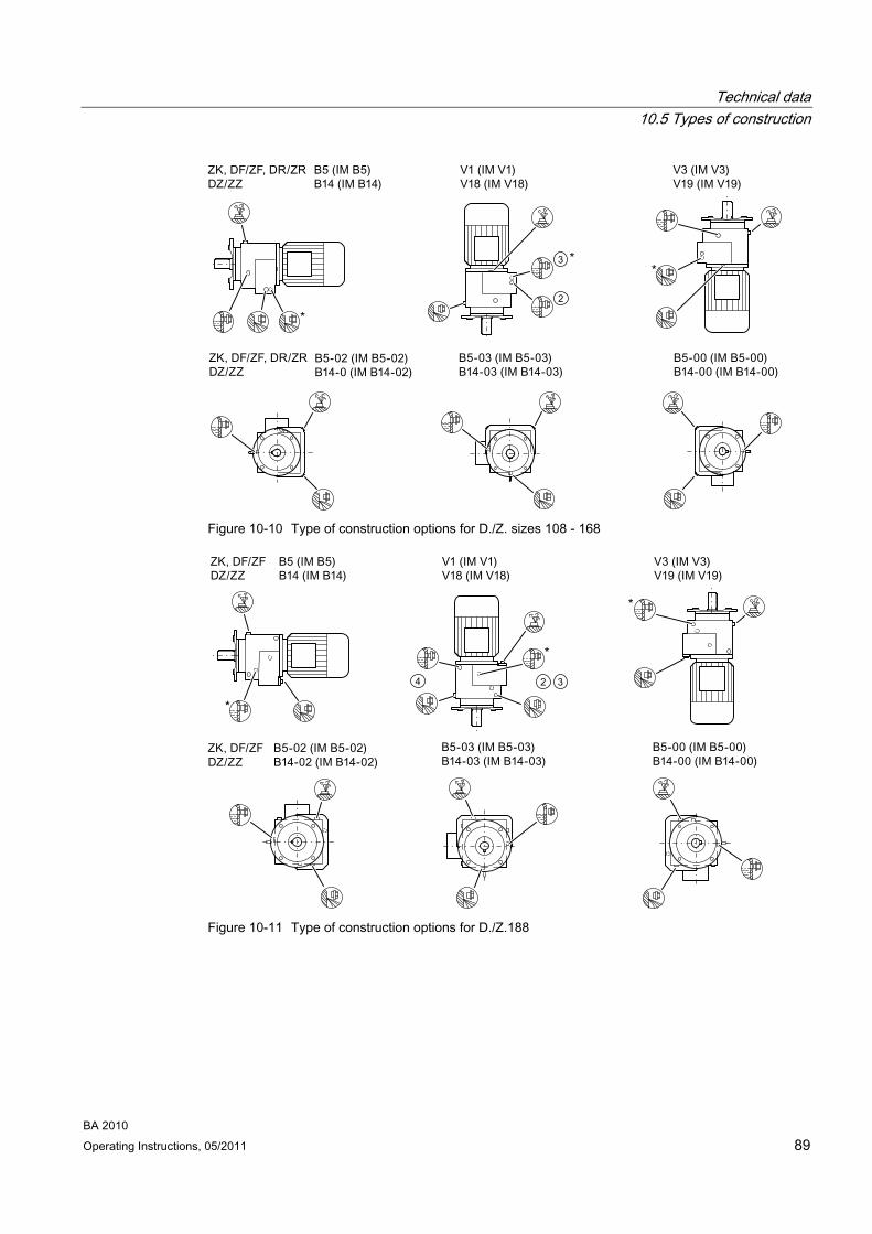
Technical data 10.5 Types of construction
BA 2010 Operating Instructions, 05/2011 89
Figure 10-10 Type of construction options for D./Z. sizes 108 - 168
Figure 10-11 Type of construction options for D./Z.188

Technical data 10.5 Types of construction
BA 2010 90 Operating Instructions, 05/2011
10.5.3 Parallel shaft gearboxes
Note
On types of construction V3-00/H-06, use the opening marked "F" to check the oil level.
Figure 10-12 Type of construction options for F.28, F. sizes 38B - 188B
Figure 10-13 Type of construction options for F.208

Technical data 10.5 Types of construction
BA 2010 Operating Instructions, 05/2011 91
10.5.4 Bevel helical gearboxes
Figure 10-14 Type of construction options for B. sizes 28 - 38 without additional screw plug
Figure 10-15 Type of construction options for B.38 with additional screw plug

Technical data 10.5 Types of construction
BA 2010 92 Operating Instructions, 05/2011
The types of construction shown apply also to the foot- / flange-mounted housing in size 188.
Figure 10-16 Image of foot- / flange-mounted housing K.188
Note
On types of construction B3-00/H-01, use the opening marked "K" to check the oil level.
Figure 10-17 Type of construction options for K, KA, KAS, KAT sizes 38 - 188
Figure 10-18 Type of construction options for KZ, KF, KM, KAD, KAZ, KAF, KAM, KADS, KAZS,
KAFS, KADT, KAZT, KAFT sizes 38 - 188
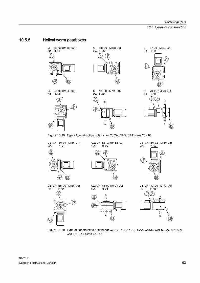
Technical data 10.5 Types of construction
BA 2010 Operating Instructions, 05/2011 93
10.5.5 Helical worm gearboxes
Figure 10-19 Type of construction options for C, CA, CAS, CAT sizes 28 - 88
Figure 10-20 Type of construction options for CZ, CF, CAD, CAF, CAZ, CADS, CAFS, CAZS, CADT,
CAFT, CAZT sizes 28 - 88

Technical data 10.6 Oil quantities
BA 2010 94 Operating Instructions, 05/2011
10.5.6 Tandem gearboxes - Intermediate helical gearboxes
Note
In a horizontal operating position the bulging part of the housing of the 2nd gearbox generally faces vertically downwards.
Note
Where tandem gearboxes are concerned, each individual gearbox is to be considered separately.
Gearbox sizes 28 and 38 on the 2nd gearbox are lubricated for life.
Screw plugs are not provided.
Horizontal operating position Vertical operating position
a Main gearbox b 2nd gearbox (intermediate helical gearbox) * On opposite side ② 2-stage gearbox ③ 3-stage gearbox
Figure 10-21 Operating position for tandem gearbox
10.6 Oil quantities
CAUTION Incorrect oil quantities damage the gearbox.
The oil quantities listed in the tables are guide values for changing the oil. They are used, for example, for lubricant storage and procurement. The precise values depend on the number of stages and transmission ratio of the gearbox.
The oil level must be checked before commissioning.
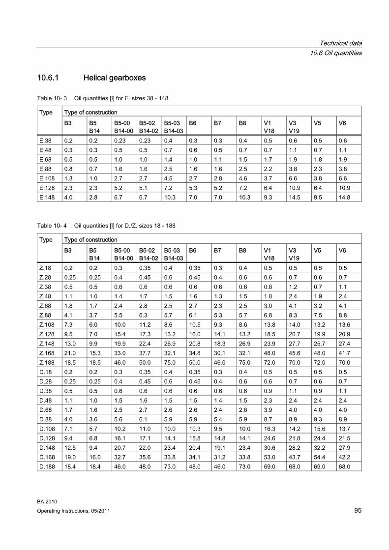
Technical data 10.6 Oil quantities
BA 2010 Operating Instructions, 05/2011 95
10.6.1 Helical gearboxes
Table 10- 3 Oil quantities [l] for E. sizes 38 - 148
Type of construction Type
B3 B5 B14
B5-00 B14-00
B5-02 B14-02
B5-03 B14-03
B6 B7 B8 V1 V18
V3 V19
V5 V6
E.38 0.2 0.2 0.23 0.23 0.4 0.3 0.3 0.4 0.5 0.6 0.5 0.6 E.48 0.3 0.3 0.5 0.5 0.7 0.6 0.5 0.7 0.7 1.1 0.7 1.1 E.68 0.5 0.5 1.0 1.0 1.4 1.0 1.1 1.5 1.7 1.9 1.8 1.9 E.88 0.8 0.7 1.6 1.6 2.5 1.6 1.6 2.5 2.2 3.8 2.3 3.8 E.108 1.3 1.0 2.7 2.7 4.5 2.7 2.8 4.6 3.7 6.6 3.8 6.6 E.128 2.3 2.3 5.2 5.1 7.2 5.3 5.2 7.2 6.4 10.9 6.4 10.9 E.148 4.0 2.8 6.7 6.7 10.3 7.0 7.0 10.3 9.3 14.5 9.5 14.8
Table 10- 4 Oil quantities [l] for D./Z. sizes 18 - 188
Type of construction Type
B3 B5 B14
B5-00 B14-00
B5-02 B14-02
B5-03 B14-03
B6 B7 B8 V1 V18
V3 V19
V5 V6
Z.18 0.2 0.2 0.3 0.35 0.4 0.35 0.3 0.4 0.5 0.5 0.5 0.5 Z.28 0.25 0.25 0.4 0.45 0.6 0.45 0.4 0.6 0.6 0.7 0.6 0.7 Z.38 0.5 0.5 0.6 0.6 0.6 0.6 0.6 0.6 0.8 1.2 0.7 1.1 Z.48 1.1 1.0 1.4 1.7 1.5 1.6 1.3 1.5 1.8 2.4 1.9 2.4 Z.68 1.8 1.7 2.4 2.8 2.5 2.7 2.3 2.5 3.0 4.1 3.2 4.1 Z.88 4.1 3.7 5.5 6.3 5.7 6.1 5.3 5.7 6.8 8.3 7.5 8.8 Z.108 7.3 6.0 10.0 11.2 8.6 10.5 9.3 8.6 13.8 14.0 13.2 13.6 Z.128 9.5 7.0 15.4 17.3 13.2 16.0 14.1 13.2 18.5 20.7 19.9 20.9 Z.148 13.0 9.9 19.9 22.4 26.9 20.8 18.3 26.9 23.9 27.7 25.7 27.4 Z.168 21.0 15.3 33.0 37.7 32.1 34.8 30.1 32.1 48.0 45.6 48.0 41.7 Z.188 18.5 18.5 46.0 50.0 75.0 50.0 46.0 75.0 72.0 70.0 72.0 70.0 D.18 0.2 0.2 0.3 0.35 0.4 0.35 0.3 0.4 0.5 0.5 0.5 0.5 D.28 0.25 0.25 0.4 0.45 0.6 0.45 0.4 0.6 0.6 0.7 0.6 0.7 D.38 0.5 0.5 0.6 0.6 0.6 0.6 0.6 0.6 0.9 1.1 0.9 1.1 D.48 1.1 1.0 1.5 1.6 1.5 1.5 1.4 1.5 2.3 2.4 2.4 2.4 D.68 1.7 1.6 2.5 2.7 2.6 2.6 2.4 2.6 3.9 4.0 4.0 4.0 D.88 4.0 3.6 5.6 6.1 5.9 5.9 5.4 5.9 8.7 8.9 9.3 8.9 D.108 7.1 5.7 10.2 11.0 10.0 10.3 9.5 10.0 16.3 14.2 15.6 13.7 D.128 9.4 6.8 16.1 17.1 14.1 15.8 14.8 14.1 24.6 21.8 24.4 21.5 D.148 12.5 9.4 20.7 22.0 23.4 20.4 19.1 23.4 30.6 28.2 32.2 27.9 D.168 19.0 16.0 32.7 35.6 33.8 34.1 31.2 33.8 53.0 43.7 54.4 42.2 D.188 18.4 18.4 46.0 48.0 73.0 48.0 46.0 73.0 69.0 68.0 69.0 68.0

Technical data 10.6 Oil quantities
BA 2010 96 Operating Instructions, 05/2011
10.6.2 Parallel shaft gearboxes
Table 10- 5 Oil quantities [l] for F. sizes 28, 38B - 188B, 208
Type of construction Type
B5-01 H-01
B5-03 H-02
B5-02 H-03
B5-00 H-04
V1-00 H-05
V3-00 H-06
FZ.28 0.6 0.45 0.5 0.5 0.65 0.85 FZ.38B 0.7 0.6 0.7 0.7 1.0 1.1 FZ.48B 1.6 1.0 1.3 1.3 1.8 2.1 FZ.68B 2.5 2.3 2.4 2.3 3.3 3.8 FZ.88B 4.5 5.0 4.8 4.6 7.0 6.6 FZ.108B 7.4 9.2 8.4 8.1 11.1 13.1 FZ.128B 13.8 13.7 15.5 14.8 22.1 22.7 FZ.148B 19.5 20.8 22.7 22.3 34.5 33.5 FZ.168B 32.8 30.0 37.0 35.8 53.8 53.0 FZ.188B 41.4 40.7 44.2 46.5 68.0 66.4 FZ.208 77.0 64.5 73.8 66.3 108.7 112.2 FD.28 0.6 0.45 0.5 0.5 0.65 0.75 FD.38B 0.9 0.6 0.7 0.7 0.9 1.1 FD.48B 2.0 0.9 1.3 1.3 1.8 2.0 FD.68B 3.3 2.3 2.4 2.3 3.2 3.8 FD.88B 6.3 5.0 4.7 4.7 6.8 6.7 FD.108B 10.6 9.1 8.2 8.2 11.1 13.0 FD.128B 16.8 13.5 15.2 14.8 21.6 22.5 FD.148B 24.7 20.3 21.8 22.3 33.6 32.6 FD.168B 44.0 28.8 36.0 35.8 52.4 51.9 FD.188B 52.0 38.4 44.5 54.1 66.0 65.2 FD.208 95.4 61.5 71.5 66.2 104.6 108.6
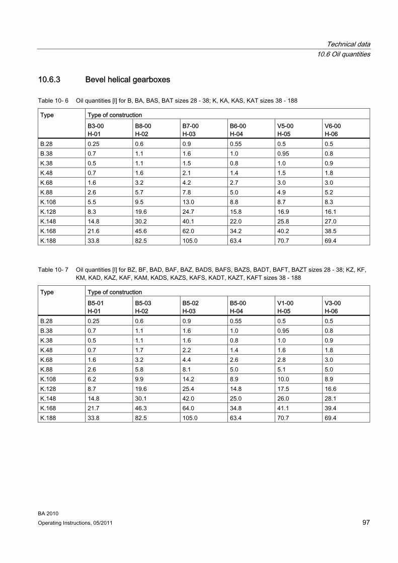
Technical data 10.6 Oil quantities
BA 2010 Operating Instructions, 05/2011 97
10.6.3 Bevel helical gearboxes
Table 10- 6 Oil quantities [l] for B, BA, BAS, BAT sizes 28 - 38; K, KA, KAS, KAT sizes 38 - 188
Type of construction Type
B3-00 H-01
B8-00 H-02
B7-00 H-03
B6-00 H-04
V5-00 H-05
V6-00 H-06
B.28 0.25 0.6 0.9 0.55 0.5 0.5 B.38 0.7 1.1 1.6 1.0 0.95 0.8 K.38 0.5 1.1 1.5 0.8 1.0 0.9 K.48 0.7 1.6 2.1 1.4 1.5 1.8 K.68 1.6 3.2 4.2 2.7 3.0 3.0 K.88 2.6 5.7 7.8 5.0 4.9 5.2 K.108 5.5 9.5 13.0 8.8 8.7 8.3 K.128 8.3 19.6 24.7 15.8 16.9 16.1 K.148 14.8 30.2 40.1 22.0 25.8 27.0 K.168 21.6 45.6 62.0 34.2 40.2 38.5 K.188 33.8 82.5 105.0 63.4 70.7 69.4
Table 10- 7 Oil quantities [l] for BZ, BF, BAD, BAF, BAZ, BADS, BAFS, BAZS, BADT, BAFT, BAZT sizes 28 - 38; KZ, KF, KM, KAD, KAZ, KAF, KAM, KADS, KAZS, KAFS, KADT, KAZT, KAFT sizes 38 - 188
Type of construction Type
B5-01 H-01
B5-03 H-02
B5-02 H-03
B5-00 H-04
V1-00 H-05
V3-00 H-06
B.28 0.25 0.6 0.9 0.55 0.5 0.5 B.38 0.7 1.1 1.6 1.0 0.95 0.8 K.38 0.5 1.1 1.6 0.8 1.0 0.9 K.48 0.7 1.7 2.2 1.4 1.6 1.8 K.68 1.6 3.2 4.4 2.6 2.8 3.0 K.88 2.6 5.8 8.1 5.0 5.1 5.0 K.108 6.2 9.9 14.2 8.9 10.0 8.9 K.128 8.7 19.6 25.4 14.8 17.5 16.6 K.148 14.8 30.1 42.0 25.0 26.0 28.1 K.168 21.7 46.3 64.0 34.8 41.1 39.4 K.188 33.8 82.5 105.0 63.4 70.7 69.4

Technical data 10.6 Oil quantities
BA 2010 98 Operating Instructions, 05/2011
10.6.4 Helical worm gearboxes
Table 10- 8 Oil quantities [l] for C, CA, CAS, CAT sizes 28 - 88
Type of construction Type
B3-00 H-01
B8-00 H-02
B7-00 H-03
B6-00 H-04
V5-00 H-05
V6-00 H-06
C.28 0.2 0.4 0.6 0.2 0.6 0.35 C.38 0.5 1.2 1.3 1.2 1.2 1.2 C.48 0.7 1.6 1.7 1.6 1.3 1.3 C.68 1.5 3.3 4.1 3.3 2.8 2.9 C.88 1.7 6.1 6.5 5.1 4.5 4.5
Table 10- 9 Oil quantities [l] for CZ, CF, CAD, CAF, CAZ, CADS, CAFS, CAZS, CADT, CAFT, CAZT sizes 28 - 88
Type of construction Type
B5-01 H-01
B5-03 H-02
B5-02 H-03
B5-00 H-04
V1-00 H-05
V3-00 H-06
C.28 0.2 0.4 0.6 0.2 0.6 0.35 C.38 0.4 1.2 1.3 1.1 1.0 1.0 C.48 0.5 1.7 1.8 1.6 1.3 1.3 C.68 1.5 3.6 4.2 3.3 3.1 3.2 C.88 1.7 5.9 7.3 5.2 4.8 4.8
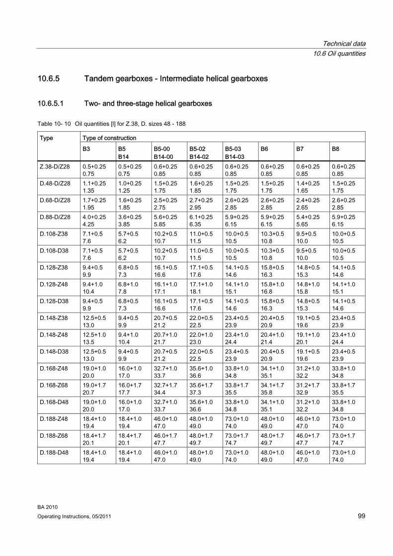
Technical data 10.6 Oil quantities
BA 2010 Operating Instructions, 05/2011 99
10.6.5 Tandem gearboxes - Intermediate helical gearboxes
10.6.5.1 Two- and three-stage helical gearboxes
Table 10- 10 Oil quantities [l] for Z.38, D. sizes 48 - 188
Type of construction Type
B3 B5 B14
B5-00 B14-00
B5-02 B14-02
B5-03 B14-03
B6 B7 B8
Z.38-D/Z28 0.5+0.25 0.75
0.5+0.25 0.75
0.6+0.25 0.85
0.6+0.25 0.85
0.6+0.25 0.85
0.6+0.25 0.85
0.6+0.25 0.85
0.6+0.25 0.85
D.48-D/Z28 1.1+0.25 1.35
1.0+0.25 1.25
1.5+0.25 1.75
1.6+0.25 1.85
1.5+0.25 1.75
1.5+0.25 1.75
1.4+0.25 1.65
1.5+0.25 1.75
D.68-D/Z28 1.7+0.25 1.95
1.6+0.25 1.85
2.5+0.25 2.75
2.7+0.25 2.95
2.6+0.25 2.85
2.6+0.25 2.85
2.4+0.25 2.65
2.6+0.25 2.85
D.88-D/Z28 4.0+0.25 4.25
3.6+0.25 3.85
5.6+0.25 5.85
6.1+0.25 6.35
5.9+0.25 6.15
5.9+0.25 6.15
5.4+0.25 5.65
5.9+0.25 6.15
D.108-Z38 7.1+0.5 7.6
5.7+0.5 6.2
10.2+0.5 10.7
11.0+0.5 11.5
10.0+0.5 10.5
10.3+0.5 10.8
9.5+0.5 10.0
10.0+0.5 10.5
D.108-D38 7.1+0.5 7.6
5.7+0.5 6.2
10.2+0.5 10.7
11.0+0.5 11.5
10.0+0.5 10.5
10.3+0.5 10.8
9.5+0.5 10.0
10.0+0.5 10.5
D.128-Z38 9.4+0.5 9.9
6.8+0.5 7.3
16.1+0.5 16.6
17.1+0.5 17.6
14.1+0.5 14.6
15.8+0.5 16.3
14.8+0.5 15.3
14.1+0.5 14.6
D.128-Z48 9.4+1.0 10.4
6.8+1.0 7.8
16.1+1.0 17.1
17.1+1.0 18.1
14.1+1.0 15.1
15.8+1.0 16.8
14.8+1.0 15.8
14.1+1.0 15.1
D.128-D38 9.4+0.5 9.9
6.8+0.5 7.3
16.1+0.5 16.6
17.1+0.5 17.6
14.1+0.5 14.6
15.8+0.5 16.3
14.8+0.5 15.3
14.1+0.5 14.6
D.148-Z38 12.5+0.5 13.0
9.4+0.5 9.9
20.7+0.5 21.2
22.0+0.5 22.5
23.4+0.5 23.9
20.4+0.5 20.9
19.1+0.5 19.6
23.4+0.5 23.9
D.148-Z48 12.5+1.0 13.5
9.4+1.0 10.4
20.7+1.0 21.7
22.0+1.0 23.0
23.4+1.0 24.4
20.4+1.0 21.4
19.1+1.0 20.1
23.4+1.0 24.4
D.148-D38 12.5+0.5 13.0
9.4+0.5 9.9
20.7+0.5 21.2
22.0+0.5 22.5
23.4+0.5 23.9
20.4+0.5 20.9
19.1+0.5 19.6
23.4+0.5 23.9
D.168-Z48 19.0+1.0 20.0
16.0+1.0 17.0
32.7+1.0 33.7
35.6+1.0 36.6
33.8+1.0 34.8
34.1+1.0 35.1
31.2+1.0 32.2
33.8+1.0 34.8
D.168-Z68 19.0+1.7 20.7
16.0+1.7 17.7
32.7+1.7 34.4
35.6+1.7 37.3
33.8+1.7 35.5
34.1+1.7 35.8
31.2+1.7 32.9
33.8+1.7 35.5
D.168-D48 19.0+1.0 20.0
16.0+1.0 17.0
32.7+1.0 33.7
35.6+1.0 36.6
33.8+1.0 34.8
34.1+1.0 35.1
31.2+1.0 32.2
33.8+1.0 34.8
D.188-Z48 18.4+1.0 19.4
18.4+1.0 19.4
46.0+1.0 47.0
48.0+1.0 49.0
73.0+1.0 74.0
48.0+1.0 49.0
46.0+1.0 47.0
73.0+1.0 74.0
D.188-Z68 18.4+1.7 20.1
18.4+1.7 20.1
46.0+1.7 47.7
48.0+1.7 49.7
73.0+1.7 74.7
48.0+1.7 49.7
46.0+1.7 47.7
73.0+1.7 74.7
D.188-D48 18.4+1.0 19.4
18.4+1.0 19.4
46.0+1.0 47.0
48.0+1.0 49.0
73.0+1.0 74.0
48.0+1.0 49.0
46.0+1.0 47.0
73.0+1.0 74.0
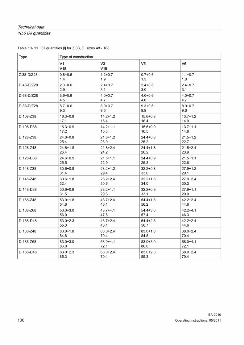
Technical data 10.6 Oil quantities
BA 2010 100 Operating Instructions, 05/2011
Table 10- 11 Oil quantities [l] for Z.38, D. sizes 48 - 188
Type of construction Type
V1 V18
V3 V19
V5 V6
Z.38-D/Z28 0.8+0.6 1.4
1.2+0.7 1.9
0.7+0.6 1.3
1.1+0.7 1.8
D.48-D/Z28 2.3+0.6 2.9
2.4+0.7 3.1
2.4+0.6 3.0
2.4+0.7 3.1
D.68-D/Z28 3.9+0.6 4.5
4.0+0.7 4.7
4.0+0.6 4.6
4.0+0.7 4.7
D.88-D/Z28 8.7+0.6 9.3
8.9+0.7 9.6
9.3+0.6 9.9
8.9+0.7 9.6
D.108-Z38 16.3+0.8 17.1
14.2+1.2 15.4
15.6+0.8 16.4
13.7+1.2 14.9
D.108-D38 16.3+0.9 17.2
14.2+1.1 15.3
15.6+0.9 16.5
13.7+1.1 14.8
D.128-Z38 24.6+0.8 25.4
21.8+1.2 23.0
24.4+0.8 25.2
21.5+1.2 22.7
D.128-Z48 24.6+1.8 26.4
21.8+2.4 24.2
24.4+1.8 26.2
21.5+2.4 23.9
D.128-D38 24.6+0.9 25.5
21.8+1.1 22.9
24.4+0.9 25.3
21.5+1.1 22.6
D.148-Z38 30.6+0.8 31.4
28.2+1.2 29.4
32.2+0.8 33.0
27.9+1.2 29.1
D.148-Z48 30.6+1.8 32.4
28.2+2.4 30.6
32.2+1.8 34.0
27.9+2.4 30.3
D.148-D38 30.6+0.9 31.5
28.2+1.1 29.3
32.2+0.9 33.1
27.9+1.1 29.0
D.168-Z48 53.0+1.8 54.8
43.7+2.4 46.1
54.4+1.8 56.2
42.2+2.4 44.6
D.168-Z68 53.0+3.0 56.0
43.7+4.1 47.8
54.4+3.0 57.4
42.2+4.1 46.3
D.168-D48 53.0+2.3 55.3
43.7+2.4 46.1
54.4+2.3 56.7
42.2+2.4 44.6
D.188-Z48 83.0+1.8 84.8
68.0+2.4 70.4
83.0+1.8 84.8
68.0+2.4 70.4
D.188-Z68 83.0+3.0 86.0
68.0+4.1 72.1
83.0+3.0 86.0
68.0+4.1 72.1
D.188-D48 83.0+2.3 85.3
68.0+2.4 70.4
83.0+2.3 85.3
68.0+2.4 70.4
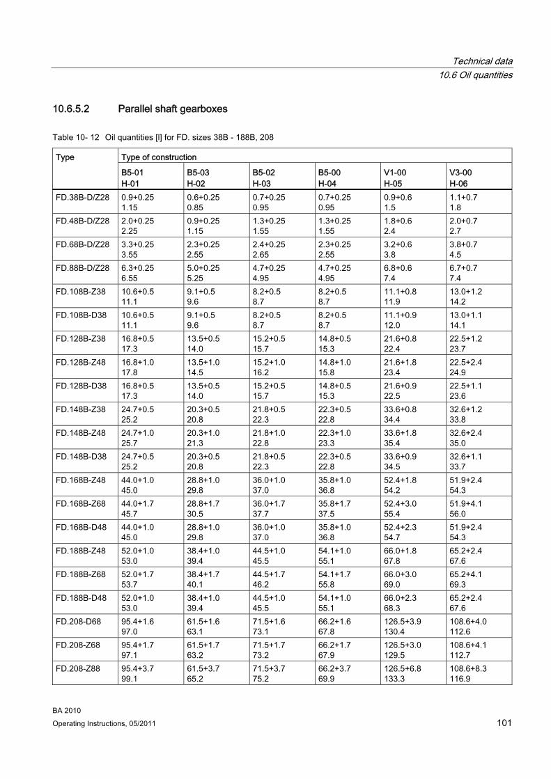
Technical data 10.6 Oil quantities
BA 2010 Operating Instructions, 05/2011 101
10.6.5.2 Parallel shaft gearboxes
Table 10- 12 Oil quantities [l] for FD. sizes 38B - 188B, 208
Type of construction Type
B5-01 H-01
B5-03 H-02
B5-02 H-03
B5-00 H-04
V1-00 H-05
V3-00 H-06
FD.38B-D/Z28 0.9+0.25 1.15
0.6+0.25 0.85
0.7+0.25 0.95
0.7+0.25 0.95
0.9+0.6 1.5
1.1+0.7 1.8
FD.48B-D/Z28 2.0+0.25 2.25
0.9+0.25 1.15
1.3+0.25 1.55
1.3+0.25 1.55
1.8+0.6 2.4
2.0+0.7 2.7
FD.68B-D/Z28 3.3+0.25 3.55
2.3+0.25 2.55
2.4+0.25 2.65
2.3+0.25 2.55
3.2+0.6 3.8
3.8+0.7 4.5
FD.88B-D/Z28 6.3+0.25 6.55
5.0+0.25 5.25
4.7+0.25 4.95
4.7+0.25 4.95
6.8+0.6 7.4
6.7+0.7 7.4
FD.108B-Z38 10.6+0.5 11.1
9.1+0.5 9.6
8.2+0.5 8.7
8.2+0.5 8.7
11.1+0.8 11.9
13.0+1.2 14.2
FD.108B-D38 10.6+0.5 11.1
9.1+0.5 9.6
8.2+0.5 8.7
8.2+0.5 8.7
11.1+0.9 12.0
13.0+1.1 14.1
FD.128B-Z38 16.8+0.5 17.3
13.5+0.5 14.0
15.2+0.5 15.7
14.8+0.5 15.3
21.6+0.8 22.4
22.5+1.2 23.7
FD.128B-Z48 16.8+1.0 17.8
13.5+1.0 14.5
15.2+1.0 16.2
14.8+1.0 15.8
21.6+1.8 23.4
22.5+2.4 24.9
FD.128B-D38 16.8+0.5 17.3
13.5+0.5 14.0
15.2+0.5 15.7
14.8+0.5 15.3
21.6+0.9 22.5
22.5+1.1 23.6
FD.148B-Z38 24.7+0.5 25.2
20.3+0.5 20.8
21.8+0.5 22.3
22.3+0.5 22.8
33.6+0.8 34.4
32.6+1.2 33.8
FD.148B-Z48 24.7+1.0 25.7
20.3+1.0 21.3
21.8+1.0 22.8
22.3+1.0 23.3
33.6+1.8 35.4
32.6+2.4 35.0
FD.148B-D38 24.7+0.5 25.2
20.3+0.5 20.8
21.8+0.5 22.3
22.3+0.5 22.8
33.6+0.9 34.5
32.6+1.1 33.7
FD.168B-Z48 44.0+1.0 45.0
28.8+1.0 29.8
36.0+1.0 37.0
35.8+1.0 36.8
52.4+1.8 54.2
51.9+2.4 54.3
FD.168B-Z68 44.0+1.7 45.7
28.8+1.7 30.5
36.0+1.7 37.7
35.8+1.7 37.5
52.4+3.0 55.4
51.9+4.1 56.0
FD.168B-D48 44.0+1.0 45.0
28.8+1.0 29.8
36.0+1.0 37.0
35.8+1.0 36.8
52.4+2.3 54.7
51.9+2.4 54.3
FD.188B-Z48 52.0+1.0 53.0
38.4+1.0 39.4
44.5+1.0 45.5
54.1+1.0 55.1
66.0+1.8 67.8
65.2+2.4 67.6
FD.188B-Z68 52.0+1.7 53.7
38.4+1.7 40.1
44.5+1.7 46.2
54.1+1.7 55.8
66.0+3.0 69.0
65.2+4.1 69.3
FD.188B-D48 52.0+1.0 53.0
38.4+1.0 39.4
44.5+1.0 45.5
54.1+1.0 55.1
66.0+2.3 68.3
65.2+2.4 67.6
FD.208-D68 95.4+1.6 97.0
61.5+1.6 63.1
71.5+1.6 73.1
66.2+1.6 67.8
126.5+3.9 130.4
108.6+4.0 112.6
FD.208-Z68 95.4+1.7 97.1
61.5+1.7 63.2
71.5+1.7 73.2
66.2+1.7 67.9
126.5+3.0 129.5
108.6+4.1 112.7
FD.208-Z88 95.4+3.7 99.1
61.5+3.7 65.2
71.5+3.7 75.2
66.2+3.7 69.9
126.5+6.8 133.3
108.6+8.3 116.9

Technical data 10.6 Oil quantities
BA 2010 102 Operating Instructions, 05/2011
10.6.5.3 Bevel helical gearboxes
Table 10- 13 Oil quantities [l] for K, KA, KAS, KAT sizes 38 - 188
Type of construction Type
B3-00 H-01
B8-00 H-02
B7-00 H-03
B6-00 H-04
V5-00 H-05
V6-00 H-06
K.38-D/Z28 0.5+0.25 0.75
1.1+0.25 1.35
1.5+0.6 2.1
0.8+0.7 1.5
1.0+0.25 1.25
0.9+0.25 1.15
K.48-D/Z28 0.7+0.25 0.95
1.6+0.25 1.85
2.1+0.6 2.7
1.4+0.7 2.1
1.5+0.25 1.75
1.8+0.25 2.05
K.68-D/Z28 1.6+0.25 1.85
3.2+0.25 3.45
4.2+0.6 4.8
2.7+0.7 3.4
3.0+0.25 3.25
3.0+0.25 3.25
K.88-D/Z28 2.6+0.25 2.85
5.7+0.25 5.95
7.8+0.6 8.4
5.0+0.7 5.7
4.9+0.25 5.15
5.2+0.25 5.45
K.108-Z38 5.5+0.5 6.0
9.5+0.5 10.0
13.0+0.8 13.8
8.8+1.2 10.0
8.7+0.5 9.2
8.3+0.5 8.8
K.108-Z48 5.5+1.0 6.5
9.5+1.0 10.5
13.0+1.8 14.8
8.8+2.4 11.2
8.7+1.0 9.7
8.3+1.0 9.3
K.108-D38 5.5+0.5 6.0
9.5+0.5 10.0
13.0+0.9 13.9
8.8+1.1 9.9
8.7+0.5 9.2
8.3+0.5 8.8
K.128-Z38 8.3+0.5 8.8
19.6+0.5 20.1
24.7+0.8 25.5
15.8+1.2 17.0
16.9+0.5 17.4
16.1+0.5 16.6
K.128-Z48 8.3+1.0 9.3
19.6+1.0 20.6
24.7+1.8 26.5
15.8+2.4 18.2
16.9+1.0 17.9
16.1+1.0 17.1
K.128-D38 8.3+0.5 8.8
19.6+0.5 20.1
24.7+0.9 25.6
15.8+1.1 16.9
16.9+0.5 17.4
16.1+0.5 16.6
K.148-Z38 14.8+0.5 15.3
30.2+0.5 30.7
40.1+0.8 40.9
22.0+1.2 23.2
25.8+0.5 26.3
27.0+0.5 27.5
K.148-Z68 14.8+1.7 16.5
30.2+1.7 31.9
40.1+3.0 43.1
22.0+4.1 26.1
25.8+1.7 27.5
27.0+1.7 28.7
K.148-D38 14.8+0.5 15.3
30.2+0.5 30.7
40.1+0.9 40.9
22.0+1.1 23.1
25.8+0.5 26.3
27.0+0.5 27.5
K.168-Z48 21.6+1.0 22.6
45.6+1.0 46.6
62.0+1.8 63.8
34.2+2.4 36.6
40.2+1.0 41.2
38.5+1.0 39.5
K.168-Z.68 21.6+1.7 23.3
45.6+1.7 47.3
62.0+3.0 65.0
34.2+4.1 38.3
40.2+1.7 41.9
38.5+1.7 40.2
K.168-D48 21.6+1.0 22.6
45.6+1.0 46.6
62.0+2.3 64.3
34.2+2.4 36.6
40.2+1.0 41.2
38.5+1.0 39.5
K.188-Z68 33.8+1.7 35.5
82.5+1.7 84.2
105.0+3.0 108.0
63.4+4.1 67.5
70.7+1.7 72.4
69.4+1.7 71.1
K.188-Z88 33.8+3.7 37.5
82.5+3.7 86.2
105.0+6.8 111.8
63.4+8.3 71.7
70.7+3.7 74.4
69.4+3.7 73.1
K.188-D68 33.8+1.6 35.4
82.5+1.6 84.1
105.0+3.9 108.9
63.4+4.0 67.4
70.7+1.6 72.3
69.4+1.6 71.0
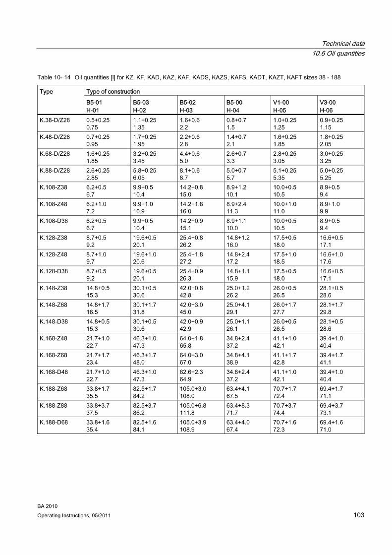
Technical data 10.6 Oil quantities
BA 2010 Operating Instructions, 05/2011 103
Table 10- 14 Oil quantities [l] for KZ, KF, KAD, KAZ, KAF, KADS, KAZS, KAFS, KADT, KAZT, KAFT sizes 38 - 188
Type of construction Type
B5-01 H-01
B5-03 H-02
B5-02 H-03
B5-00 H-04
V1-00 H-05
V3-00 H-06
K.38-D/Z28 0.5+0.25 0.75
1.1+0.25 1.35
1.6+0.6 2.2
0.8+0.7 1.5
1.0+0.25 1.25
0.9+0.25 1.15
K.48-D/Z28 0.7+0.25 0.95
1.7+0.25 1.95
2.2+0.6 2.8
1.4+0.7 2.1
1.6+0.25 1.85
1.8+0.25 2.05
K.68-D/Z28 1.6+0.25 1.85
3.2+0.25 3.45
4.4+0.6 5.0
2.6+0.7 3.3
2.8+0.25 3.05
3.0+0.25 3.25
K.88-D/Z28 2.6+0.25 2.85
5.8+0.25 6.05
8.1+0.6 8.7
5.0+0.7 5.7
5.1+0.25 5.35
5.0+0.25 5.25
K.108-Z38 6.2+0.5 6.7
9.9+0.5 10.4
14.2+0.8 15.0
8.9+1.2 10.1
10.0+0.5 10.5
8.9+0.5 9.4
K.108-Z48 6.2+1.0 7.2
9.9+1.0 10.9
14.2+1.8 16.0
8.9+2.4 11.3
10.0+1.0 11.0
8.9+1.0 9.9
K.108-D38 6.2+0.5 6.7
9.9+0.5 10.4
14.2+0.9 15.1
8.9+1.1 10.0
10.0+0.5 10.5
8.9+0.5 9.4
K.128-Z38 8.7+0.5 9.2
19.6+0.5 20.1
25.4+0.8 26.2
14.8+1.2 16.0
17.5+0.5 18.0
16.6+0.5 17.1
K.128-Z48 8.7+1.0 9.7
19.6+1.0 20.6
25.4+1.8 27.2
14.8+2.4 17.2
17.5+1.0 18.5
16.6+1.0 17.6
K.128-D38 8.7+0.5 9.2
19.6+0.5 20.1
25.4+0.9 26.3
14.8+1.1 15.9
17.5+0.5 18.0
16.6+0.5 17.1
K.148-Z38 14.8+0.5 15.3
30.1+0.5 30.6
42.0+0.8 42.8
25.0+1.2 26.2
26.0+0.5 26.5
28.1+0.5 28.6
K.148-Z68 14.8+1.7 16.5
30.1+1.7 31.8
42.0+3.0 45.0
25.0+4.1 29.1
26.0+1.7 27.7
28.1+1.7 29.8
K.148-D38 14.8+0.5 15.3
30.1+0.5 30.6
42.0+0.9 42.9
25.0+1.1 26.1
26.0+0.5 26.5
28.1+0.5 28.6
K.168-Z48 21.7+1.0 22.7
46.3+1.0 47.3
64.0+1.8 65.8
34.8+2.4 37.2
41.1+1.0 42.1
39.4+1.0 40.4
K.168-Z68 21.7+1.7 23.4
46.3+1.7 48.0
64.0+3.0 67.0
34.8+4.1 38.9
41.1+1.7 42.8
39.4+1.7 41.1
K.168-D48 21.7+1.0 22.7
46.3+1.0 47.3
62.6+2.3 64.9
34.8+2.4 37.2
41.1+1.0 42.1
39.4+1.0 40.4
K.188-Z68 33.8+1.7 35.5
82.5+1.7 84.2
105.0+3.0 108.0
63.4+4.1 67.5
70.7+1.7 72.4
69.4+1.7 71.1
K.188-Z88 33.8+3.7 37.5
82.5+3.7 86.2
105.0+6.8 111.8
63.4+8.3 71.7
70.7+3.7 74.4
69.4+3.7 73.1
K.188-D68 33.8+1.6 35.4
82.5+1.6 84.1
105.0+3.9 108.9
63.4+4.0 67.4
70.7+1.6 72.3
69.4+1.6 71.0
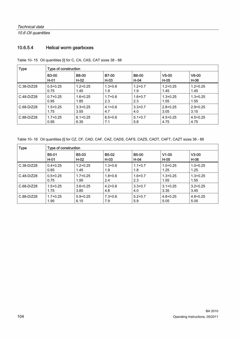
Technical data 10.6 Oil quantities
BA 2010 104 Operating Instructions, 05/2011
10.6.5.4 Helical worm gearboxes
Table 10- 15 Oil quantities [l] for C, CA, CAS, CAT sizes 38 - 88
Type of construction Type
B3-00 H-01
B8-00 H-02
B7-00 H-03
B6-00 H-04
V5-00 H-05
V6-00 H-06
C.38-D/Z28 0.5+0.25 0.75
1.2+0.25 1.45
1.3+0.6 1.9
1.2+0.7 1.9
1.2+0.25 1.45
1.2+0.25 1.45
C.48-D/Z28 0.7+0.25 0.95
1.6+0.25 1.85
1.7+0.6 2.3
1.6+0.7 2.3
1.3+0.25 1.55
1.3+0.25 1.55
C.68-D/Z28 1.5+0.25 1.75
3.3+0.25 3.55
4.1+0.6 4.7
3.3+0.7 4.0
2.8+0.25 3.05
2.9+0.25 3.15
C.88-D/Z28 1.7+0.25 0.95
6.1+0.25 6.35
6.5+0.6 7.1
5.1+0.7 5.8
4.5+0.25 4.75
4.5+0.25 4.75
Table 10- 16 Oil quantities [l] for CZ, CF, CAD, CAF, CAZ, CADS, CAFS, CAZS, CADT, CAFT, CAZT sizes 38 - 88
Type of construction Type
B5-01 H-01
B5-03 H-02
B5-02 H-03
B5-00 H-04
V1-00 H-05
V3-00 H-06
C.38-D/Z28 0.4+0.25 0.65
1.2+0.25 1.45
1.3+0.6 1.9
1.1+0.7 1.8
1.0+0.25 1.25
1.0+0.25 1.25
C.48-D/Z28 0.5+0.25 0.75
1.7+0.25 1.95
1.8+0.6 2.4
1.6+0.7 2.3
1.3+0.25 1.55
1.3+0.25 1.55
C.68-D/Z28 1.5+0.25 1.75
3.6+0.25 3.85
4.2+0.6 4.8
3.3+0.7 4.0
3.1+0.25 3.35
3.2+0.25 3.45
C.88-D/Z28 1.7+0.25 1.95
5.9+0.25 6.15
7.3+0.6 7.9
5.2+0.7 5.9
4.8+0.25 5.05
4.8+0.25 5.05
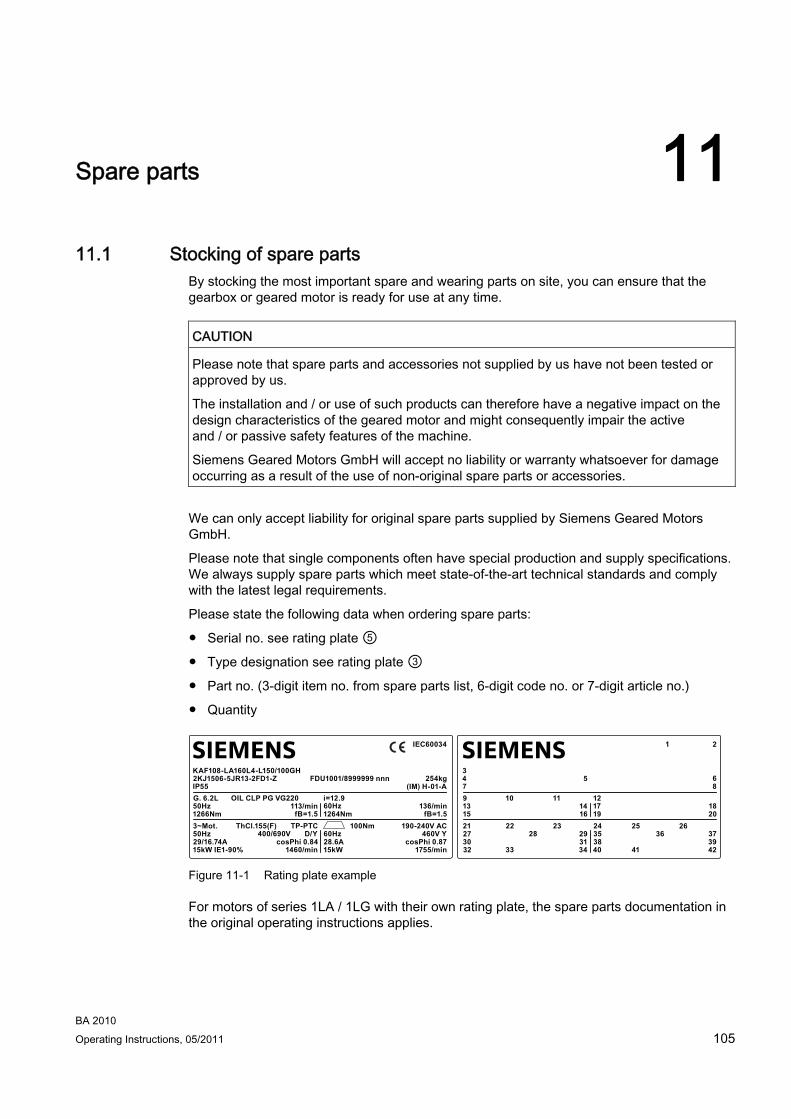
Spare parts 1111.1 Stocking of spare parts
By stocking the most important spare and wearing parts on site, you can ensure that the gearbox or geared motor is ready for use at any time.
CAUTION Please note that spare parts and accessories not supplied by us have not been tested or approved by us.
The installation and / or use of such products can therefore have a negative impact on the design characteristics of the geared motor and might consequently impair the active and / or passive safety features of the machine.
Siemens Geared Motors GmbH will accept no liability or warranty whatsoever for damage occurring as a result of the use of non-original spare parts or accessories.
We can only accept liability for original spare parts supplied by Siemens Geared Motors GmbH.
Please note that single components often have special production and supply specifications. We always supply spare parts which meet state-of-the-art technical standards and comply with the latest legal requirements.
Please state the following data when ordering spare parts:
● Serial no. see rating plate ⑤
● Type designation see rating plate ③
● Part no. (3-digit item no. from spare parts list, 6-digit code no. or 7-digit article no.)
● Quantity
SIEMENSSIEMENS
13
273032
31 3835
25 2636 37
393433 40 41 42
28
1521 22 23 24
29
1416 19 20
3479 10 11 12
17 18
5 6
21
8
50Hz
50Hz29/16.74A15kW IE1-90%
cosPhi 0.84 28.6A60Hz
100Nm 190-240V AC460V Y
cosPhi 0.871460/min 15kW 1755/min
400/690V
1266Nm3~Mot. ThCl.155(F) TP-PTC
D/Y
113/minfB=1.5 1264Nm fB=1.5
KAF108-LA160L4-L150/100GH2KJ1506-5JR13-2FD1-ZIP55G. 6.2L OIL CLP PG VG220 i=12.9
60Hz 136/min
FDU1001/8999999 nnn 254kg
IEC60034
(IM) H-01-A
Figure 11-1 Rating plate example
For motors of series 1LA / 1LG with their own rating plate, the spare parts documentation in the original operating instructions applies.
BA 2010 Operating Instructions, 05/2011 105
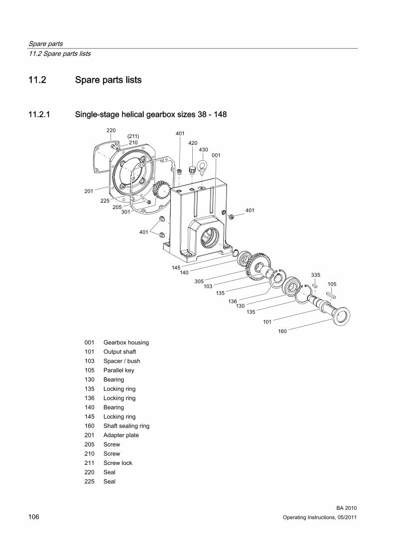
Spare parts 11.2 Spare parts lists
BA 2010 106 Operating Instructions, 05/2011
11.2 Spare parts lists
11.2.1 Single-stage helical gearbox sizes 38 - 148
001 Gearbox housing 101 Output shaft 103 Spacer / bush 105 Parallel key 130 Bearing 135 Locking ring 136 Locking ring 140 Bearing 145 Locking ring 160 Shaft sealing ring 201 Adapter plate 205 Screw 210 Screw 211 Screw lock 220 Seal 225 Seal
Spare parts 11.2 Spare parts lists
BA 2010 Operating Instructions, 05/2011 107
301 Plug-in pinion 305 Helical gear wheel 335 Parallel key 401 Screw plug 420 Vent filter 430 Eyebolt
Figure 11-2 Single-stage helical gearbox sizes 38 - 148

Spare parts 11.2 Spare parts lists
BA 2010 108 Operating Instructions, 05/2011
11.2.2 Two- and three-stage helical gearbox sizes 38 - 188
* 2-stage 001 Gearbox housing 020 Bearing 025 Locking ring 030 Bearing 050 Housing cover 051 Screw 055 Seal 101 Output shaft 103 Spacer / bush 105 Parallel key 130 Bearing 135 Locking ring 140 Bearing 141 Supporting disk / shim 144 Supporting disk / shim 145 Locking ring
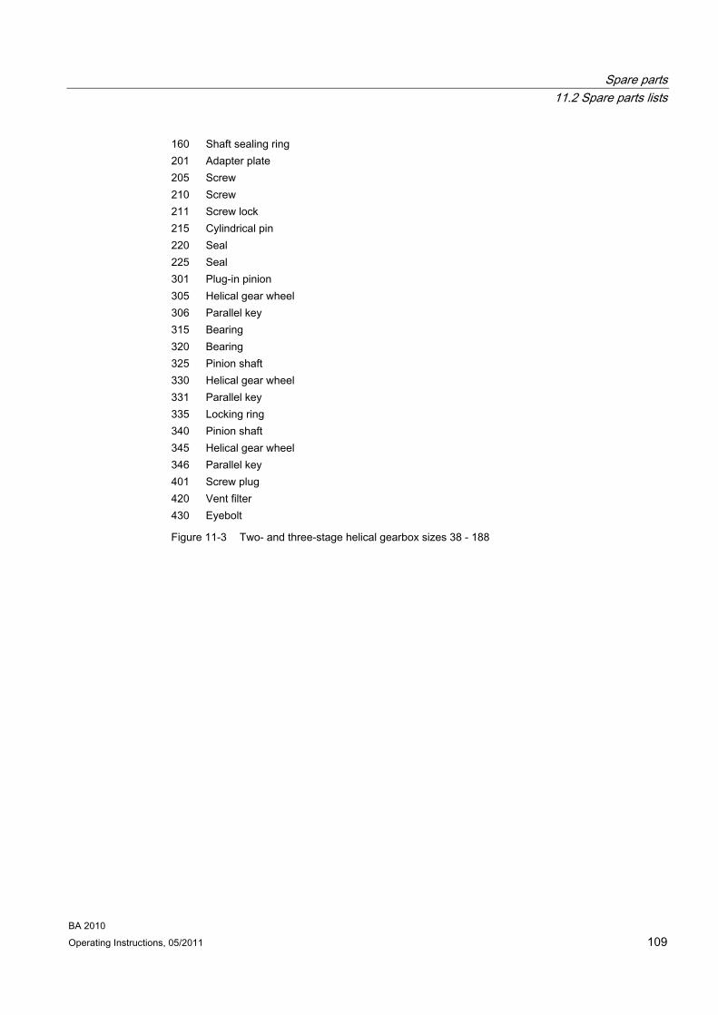
Spare parts 11.2 Spare parts lists
BA 2010 Operating Instructions, 05/2011 109
160 Shaft sealing ring 201 Adapter plate 205 Screw 210 Screw 211 Screw lock 215 Cylindrical pin 220 Seal 225 Seal 301 Plug-in pinion 305 Helical gear wheel 306 Parallel key 315 Bearing 320 Bearing 325 Pinion shaft 330 Helical gear wheel 331 Parallel key 335 Locking ring 340 Pinion shaft 345 Helical gear wheel 346 Parallel key 401 Screw plug 420 Vent filter 430 Eyebolt
Figure 11-3 Two- and three-stage helical gearbox sizes 38 - 188
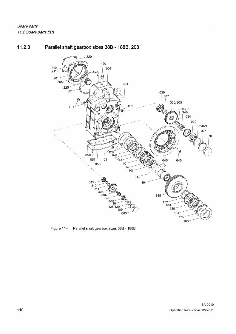
Spare parts 11.2 Spare parts lists
BA 2010 110 Operating Instructions, 05/2011
11.2.3 Parallel shaft gearbox sizes 38B - 188B, 208
Figure 11-4 Parallel shaft gearbox sizes 38B - 188B
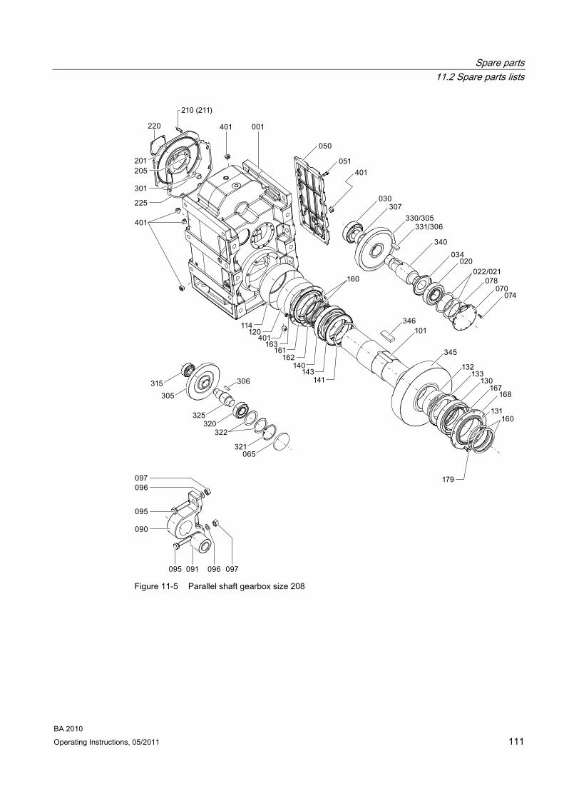
Spare parts 11.2 Spare parts lists
BA 2010 Operating Instructions, 05/2011 111
Figure 11-5 Parallel shaft gearbox size 208
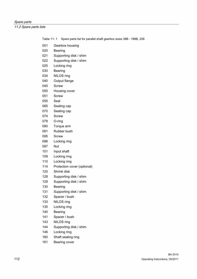
Spare parts 11.2 Spare parts lists
BA 2010 112 Operating Instructions, 05/2011
Table 11- 1 Spare parts list for parallel shaft gearbox sizes 38B - 188B, 208
001 Gearbox housing 020 Bearing 021 Supporting disk / shim 022 Supporting disk / shim 025 Locking ring 030 Bearing 034 NILOS ring 040 Output flange 045 Screw 050 Housing cover 051 Screw 055 Seal 065 Sealing cap 070 Sealing cap 074 Screw 078 O-ring 090 Torque arm 091 Rubber bush 095 Screw 096 Locking ring 097 Nut 101 Input shaft 109 Locking ring 110 Locking ring 114 Protection cover (optional) 120 Shrink disk 128 Supporting disk / shim 129 Supporting disk / shim 130 Bearing 131 Supporting disk / shim 132 Spacer / bush 133 NILOS ring 135 Locking ring 140 Bearing 141 Spacer / bush 143 NILOS ring 144 Supporting disk / shim 146 Locking ring 160 Shaft sealing ring 161 Bearing cover
Spare parts 11.2 Spare parts lists
BA 2010 Operating Instructions, 05/2011 113
162 O-ring 163 Screw 167 O-ring 168 Bearing cover 179 Screw 201 Adapter plate 205 Screw 210 Screw 211 Screw lock 220 Seal 225 Seal 301 Pinion 305 Helical gear wheel 306 Parallel key 307 Spacer / bush 310 Locking ring 311 Supporting disk / shim 315 Bearing 320 Bearing 321 Locking ring 322 Supporting disk / shim 325 Pinion shaft 330 Helical gear wheel 331 Parallel key 340 Pinion shaft 345 Helical gear wheel 346 Parallel key 401 Screw plug 420 Vent filter
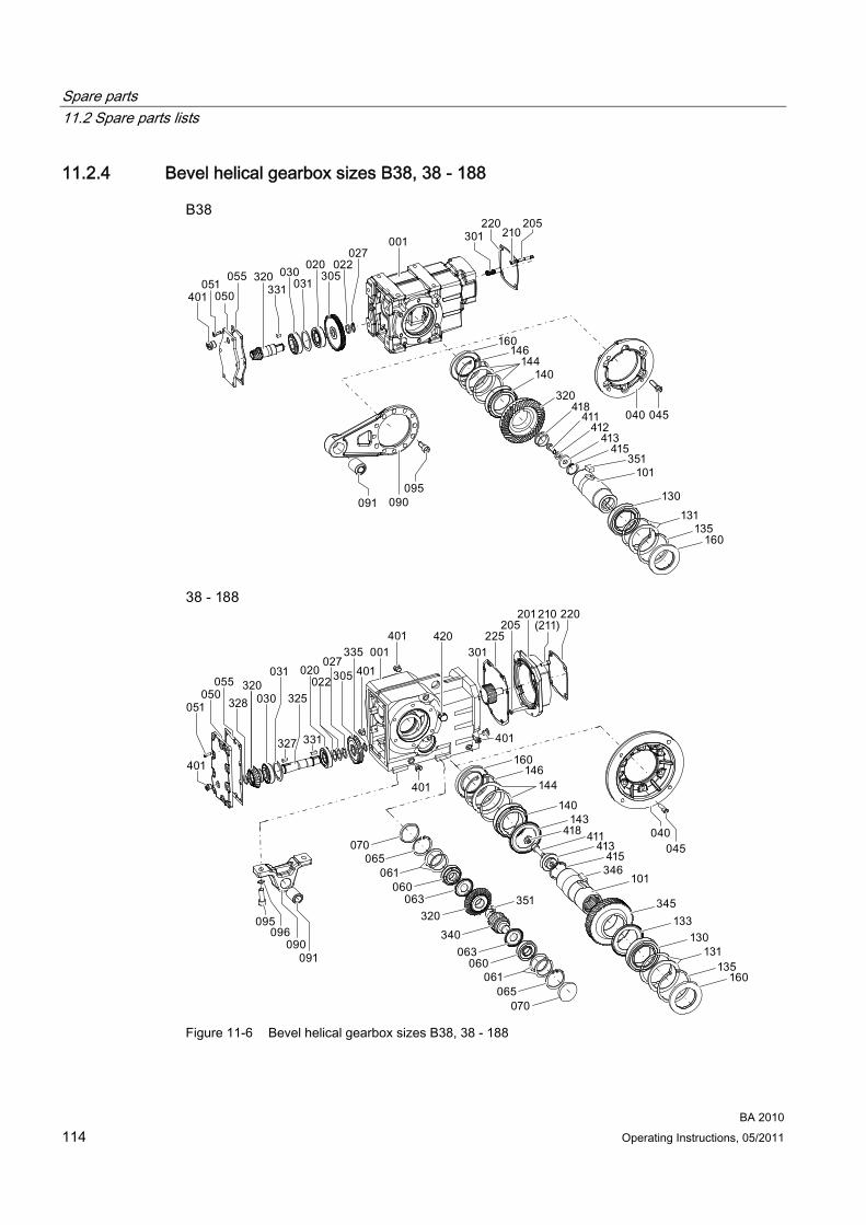
Spare parts 11.2 Spare parts lists
BA 2010 114 Operating Instructions, 05/2011
11.2.4 Bevel helical gearbox sizes B38, 38 - 188
Figure 11-6 Bevel helical gearbox sizes B38, 38 - 188

Spare parts 11.2 Spare parts lists
BA 2010 Operating Instructions, 05/2011 115
Table 11- 2 Spare parts list for bevel helical gearbox sizes B38, 38 - 188
001 Gearbox housing 020 Bearing 022 Supporting disk / shim 027 Locking ring 030 Bearing 031 Supporting disk / shim 040 Output flange 045 Screw 050 Housing cover 051 Screw 055 Seal 060 Bearing 061 Supporting disk / shim 063 NILOS ring 065 Locking ring 070 Sealing cap 090 Torque arm 091 Rubber bush 095 Screw 096 Screw lock 101 Output shaft 130 Bearing 131 Supporting disk / shim 133 NILOS ring 135 Locking ring 140 Bearing 143 NILOS ring 144 Supporting disk / shim 146 Locking ring 160 Shaft sealing ring 201 Adapter plate 205 Screw 210 Screw 211 Screw lock 220 Seal 225 Seal 301 Plug-in pinion 305 Helical gear wheel 320 Bevel gear pair 325 Bevel pinion shaft

Spare parts 11.2 Spare parts lists
BA 2010 116 Operating Instructions, 05/2011
327 Parallel key 328 Locking ring 331 Parallel key 335 Locking ring 340 Pinion shaft 345 Helical gear wheel 346 Parallel key 351 Parallel key 401 Screw plug 411 Screw 413 Disk 415 Locking ring 418 Plug / sealing cap 420 Vent filter

Spare parts 11.2 Spare parts lists
BA 2010 Operating Instructions, 05/2011 117
11.2.5 Helical worm gearbox sizes 38 - 88
001 Gearbox housing 020 Bearing 030 Bearing 032 Supporting disk / shim 035 Locking ring 037 Locking ring 040 Output flange 045 Screw 070 Sealing cap 090 Torque arm 091 Rubber bush 095 Screw 101 Output shaft 130 Bearing 131 Supporting disk / shim 133 NILOS ring

Spare parts 11.2 Spare parts lists
BA 2010 118 Operating Instructions, 05/2011
135 Locking ring 140 Bearing 143 NILOS ring 144 Supporting disk / shim 146 Locking ring 160 Shaft sealing ring 201 Adapter plate 205 Screw 210 Screw 211 Screw lock 220 Seal 225 Seal 301 Plug-in pinion 305 Helical gear wheel 331 Parallel key 335 Locking ring 340 Worm shaft 345 Worm wheel 346 Parallel key 401 Screw plug 411 Screw 412 Screw lock 413 Disk 415 Locking ring 418 Plug / sealing cap 420 Vent filter 430 Eyebolt
Figure 11-7 Helical worm gearbox sizes 38 - 88

Declaration of Incorporation, Declaration of Conformity 1212.1 Declaration of Incorporation
Declaration of Incorporation according to Directive 2006/42/EC Annex II 1 B. The manufacturer Siemens Geared Motors GmbH, 72072 Tübingen, Germany, declares for the partly completed machine ● Single-stage helical gearboxes of types
E.38, E.48, E.68, E.88, E.108, E.128, E.148 ● Two- and three-stage helical gearboxes of types
D./Z.18, D./Z.28, D./Z.38, D./Z.48, D./Z.68, D./Z.88, D./Z.108, D./Z.128, D./Z.148, D./Z.168, D./Z.188
● Parallel shaft gearboxes of types F.28, F.38B, F.48B, F.68B, F.88B, F.108B, F.128B, F.148B, F.168B, F.188B, F.208
● Bevel helical gearboxes of types B.28, B.38, K.38, K.48, K.68, K.88, K.108, K.128, K.148, K.168, K.188
● Helical worm gearboxes of types C.28, C.38, C.48, C.68, C.88:
The special technical documentation was generated according to Annex VII B. The following essential health and safety requirements from Directive 2006/42/EC Annex I apply and have been fulfilled: ● 1.1, 1.1.2, 1.1.3, 1.1.5 ● 1.2.4.4, 1.2.6 ● 1.3.1, 1.3.2, 1.3.3, 1.3.4, 1.3.6, 1.3.8.1 ● 1.4.1, 1.4.2, 1.4.2.1 ● 1.5.1, 1.5.2, 1.5.4, 1.5.5, 1.5.6, 1.5.8, 1.5.9, 1.5.10, 1.5.11, 1.5.13, 1.5.15 ● 1.6.1, 1.6.2 ● 1.7.1, 1.7.1.1, 1.7.2, 1.7.3, 1.7.4, 1.7.4.1, 1.7.4.2, 1.7.4.3 The partly completed machine may only be commissioned once it has been established, if applicable, that the machine in which the partly completed machine is to be incorporated meets the provisions of Directive 2006/42/EC. The manufacturer is obligated to transmit the special technical documentation for the partly completed machine in electronic form to national authorities upon legitimate request. Person authorized to compile the relevant technical documentation: Georg Böing, Head of Research and Development Gears.
Tübingen, April 11, 2011
Georg Böing Head of Research & Development Gears
Jürgen Pflaum Head of Quality Management
BA 2010 Operating Instructions, 05/2011 119
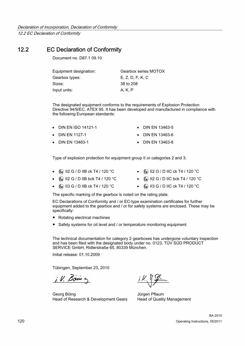
Declaration of Incorporation, Declaration of Conformity 12.2 EC Declaration of Conformity
BA 2010 120 Operating Instructions, 05/2011
12.2 EC Declaration of Conformity Document no. D87.1 09.10
Equipment designation: Gearbox series MOTOX Gearbox types: E, Z, D, F, K, C Sizes: 38 to 208 Input units: A, K, P
The designated equipment conforms to the requirements of Explosion Protection Directive 94/9/EC, ATEX 95. It has been developed and manufactured in compliance with the following European standards:
DIN EN ISO 14121-1 DIN EN 13463-5
DIN EN 1127-1 DIN EN 13463-6
DIN EN 13463-1 DIN EN 13463-8
Type of explosion protection for equipment group II or categories 2 and 3:
II2 G / D IIB ck T4 / 120 °C II2 G / D IIC ck T4 / 120 °C
II2 G / D IIB bck T4 / 120 °C II2 G / D IIC bck T4 / 120 °C
II3 G / D IIB ck T4 / 120 °C II3 G / D IIC ck T4 / 120 °C
The specific marking of the gearbox is noted on the rating plate. EC Declarations of Conformity and / or EC-type examination certificates for further equipment added to the gearbox and / or for safety systems are enclosed. These may be specifically: ● Rotating electrical machines ● Safety systems for oil level and / or temperature monitoring equipment The technical documentation for category 2 gearboxes has undergone voluntary inspection and has been filed with the designated body under no. 0123, TÜV SÜD PRODUCT SERVICE GmbH, Ridlerstraße 65, 80339 München. Initial release: 01.10.2009
Tübingen, September 23, 2010
Georg Böing Head of Research & Development Gears
Jürgen Pflaum Head of Quality Management


www.siemens.com/automation
Subject to change
© Siemens AG 2010
Siemens AGIndustry SectorPostfach 48 4890026 NÜRNBERGGERMANY
MOTOX Geared Motors on the Internet:www.siemens.com/gearedmotors
Further information