motor st arters easypact tvs - scat technologyeasypact tvs: control & protection, in a simple...
TRANSCRIPT

Motor starters
EasyPact TVS
Designed for the essential

Designed for the essential

Contents
EasyPact TVS contactors, 6 A to 630 A
EasyPact TVS thermal overload relays 0.1 A to 630 A
EasyPact TVS control relays 4 NO/NC contacts
EasyPact TVS motor protection circuit breaker 0.1A to 32A
Coordination between protection and control components
1
in a simple wayEasyPact TVS: control & protection,
Leader in the motor starter market for more than 80 years, Schneider Electric has designed EasyPact TVS range to provide you with the competitive solutions you were expecting.
EasyPact TVS starters range is the perfect fit between quality, features and price.
A cost-effective offer > The best price for the performance and quality
level you need.
> A maximum of solutions with an optimal number of products.
> Designed to perform the essential starter's functions: control and overload protection.
Simple and intuitive > Easy to install.
> Covering 80 % of applications.
> With the key accessories to easily build lots of Do-It-Yourself solutions.
> With an intuitive commercial references system: easy to order, easy to understand and easy to remember.
Guaranteed availability > Available in distribution.
> EasyPact TVS fully benefits from Schneider Electric world wide policies: in terms of standards of production, distribution, quality, availability, services and after-sales support.
2

EasyPact TVS: control & protection, in a simple way
Circuit protection
CDB500400
Tesys GS Tesys GV GZ1 E
EasyPact TVS offer Power control & protection Circuit control
3
and relays
4
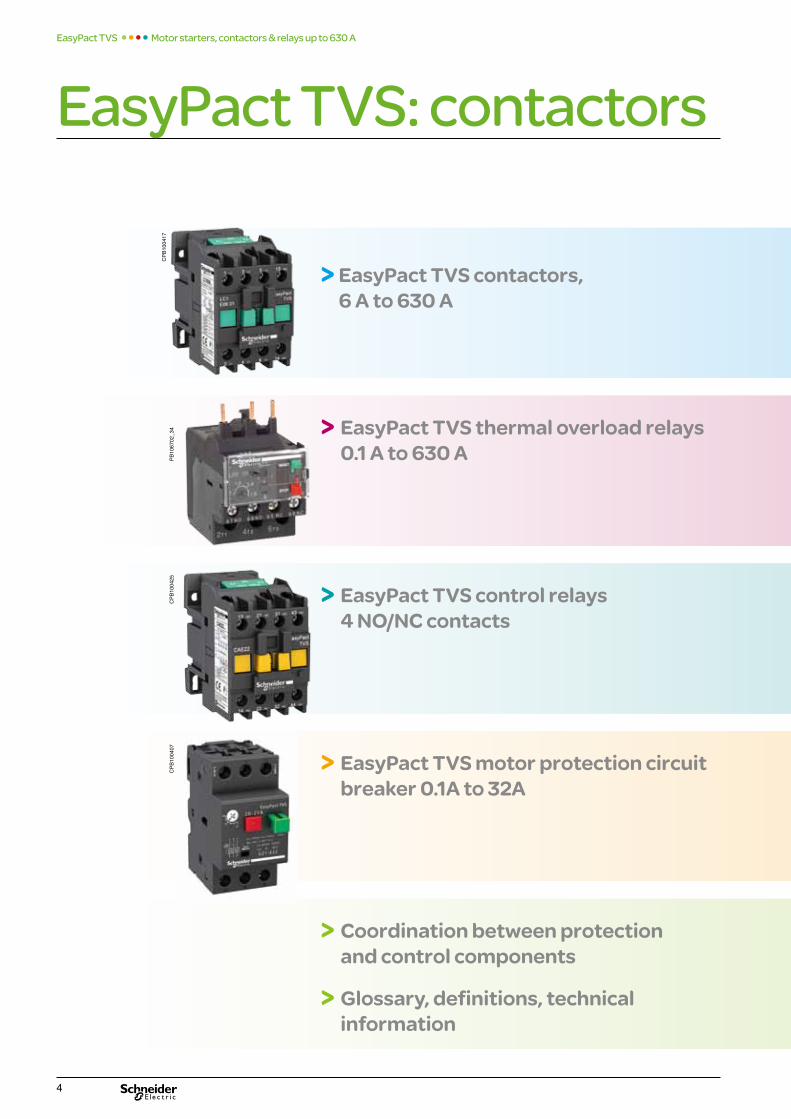
> EasyPact TVS contactors, 6 A to 630 A
CPB
1004
17
> EasyPact TVS motor protection circuit breaker 0.1A to 32A
> EasyPact TVS thermal overload relays 0.1 A to 630 A
> EasyPact TVS control relays 4 NO/NC contacts
> Coordination between protection and control components
> Glossary, definitions, technical information
EasyPact TVS: contactors Motor starters, contactors & relays up to 630 A EasyPact TVS
PB10
6702
_34
CPB
1004
25C
PB10
0407

EasyPact TVS: contactors
5
Control your motors, Do It Yourself simply your solution: direct-on-line starter, reversing starter, star-delta starter
Characteristics A-3
Accessories, spare parts A-10
Dimensions, mounting A-18
What coordination means 46Better continuity of service
Glossary 49
Definitions 50
Technical informations 51
Characteristics
Dimensions, mounting
B-1
B-7
Footprint for complete compatibility with contactors (direct mounting under contactors)
Characteristics
Dimensions, mounting
C-1
Characteristics D-1
C-4
Dimensions, mounting D-7
References D-3
Pilot your control circuits
What coordination means E-1Better continuity of service
Glossary E-4
Definitions E-5
Technical informations E-6
and relays
from 6 to 630 A
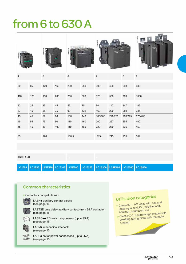
4 5 6 7 8 9
80 95 120 160 200 250 300 400 500 630
110 120 150 200 250 300 320 500 700 1000
22 25 37 45 55 75 90 110 147 185
37 45 55 75 90 132 160 200 250 335
45 45 59 80 100 140 160/185 220/250 280/295 375/400
45 55 75 90 110 160 200 257 355 400
45 45 80 100 110 160 220 280 335 450
85 120 168.5 213 213 233 309
1 NO + 1 NC - -
LC1E80 LC1E95 LC1E120 LC1E160 LC1E200 LC1E250 LC1E300 LC1E400 LC1E500 LC1E630
EasyPact TVS Motor starters, contactors & relays up to 630 A
EasyPact TVS 3 pole contactors
CPB
1004
17
CPB
1004
18 CPB
1004
19
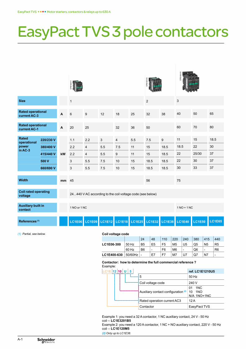
Size 1 2 3
Rated operational current AC-3 A 6 9 12 18 25 32 38 40 50 65
Rated operational current AC-1 A 20 25 32 36 50 60 70 80
Rated operational power in AC-3
220/230 V
kW
1.1 2.2 3 4 5.5 7.5 9 11 15 18.5
380/400 V 2.2 4 5.5 7.5 11 15 18.5 18.5 22 30
415/440 V 2.2 4 5.5 9 11 15 18.5 22 25/30 37
500 V 3 5.5 7.5 10 15 18.5 18.5 22 30 37
660/690 V 3 5.5 7.5 10 15 18.5 18.5 30 33 37
Width mm 45 56 75
Coil rated operating voltage 24...440 V AC according to the coil voltage code (see below)
Auxiliary built in contact 1 NO or 1 NC 1 NO + 1 NC
References (1) LC1E06 LC1E09 LC1E12 LC1E18 LC1E25 LC1E32 LC1E38 LC1E40 LC1E50 LC1E65
(1) Partial, see below. Coil voltage code 24 48 110 220 240 380 415 440
LC1E06-300 50 Hz B5 E5 F5 M5 U5 Q5 N5 R5
60 Hz B6 - F6 M6 - Q6 - R6
LC1E400-630 50/60Hz - E7 F7 M7 U7 Q7 N7 -
Contactor: how to determine the full commercial reference ? Example:
LC1E 12 10 U 5 ref. LC1E1210U5 5 50 Hz
Coil voltage code 240 V
Auxiliary contact configuration (2) 01 1NC 10 1NO N/A 1NO+1NC
Rated operation current AC3 12 A
Contactor EasyPact TVS
Example 1: you need a 32 A contactor, 1 NC auxiliary contact, 24 V - 50 Hz coil C LC1E3201B5 Example 2: you need a 120 A contactor, 1 NC + NO auxiliary contact, 220 V - 50 Hz coil C LC1E120M5 (2) Only up to LC1E38.
A-1
EasyPact TVS 3 pole contactors
Size 1 2 3
Rated operational current AC-3 A 6 9 12 18 25 32 38 40 50 65
Rated operational current AC-1 A 20 25 32 36 50 60 70 80
Rated operational powerin AC-3
220/230 V
kW
1.1 2.2 3 4 5.5 7.5 9 11 15 18.5
380/400 V 2.2 4 5.5 7.5 11 15 18.5 18.5 22 30
415/440 V 2.2 4 5.5 9 11 15 18.5 22 25/30 37
500 V 3 5.5 7.5 10 15 18.5 18.5 22 30 37
660/690 V 3 5.5 7.5 10 15 18.5 18.5 30 33 37
Width mm 45 56 75
Coil rated operating voltage 24...440 V AC according to the coil voltage code (see below)
Auxiliary built in contact 1 NO or 1 NC 1 NO + 1 NC
References (1) LC1E06 LC1E09 LC1E12 LC1E18 LC1E25 LC1E32 LC1E38 LC1E40 LC1E50 LC1E65
from 6 to 630 AC
PB10
0420
CPB
1004
21
CPB
1004
15
CPB
1004
08
CPB
1004
09
4 5 6 7 8 9
80 95 120 160 200 250 300 400 500 630
1 NO + 1 NC - -
110 120 150 200 250 300 320 500 700 1000
22 25 37 45 55 75 90 110 147 185
37 45 55 75 90 132 160 200 250 335
45 45 59 80 100 140 160/185 220/250 280/295 375/400
45 55 75 90 110 160 200 257 355 400
45 45 80 100 110 160 220 280 335 450
85 120 168.5 213 213 233 309
LC1E80 LC1E95 LC1E120 LC1E160 LC1E200 LC1E250 LC1E300 LC1E400 LC1E500 LC1E630
Utilisation categories
> Class AC-1: AC loads with cos j at
least equal to 0.95 (resistive load,
heating, distribution, etc.).
> Class AC-3: squirrel-cage motors with
breaking taking place with the motor
running.
Common characteristics
> Contactors compatible with:
LAENp auxiliary contact blocks (see page 16)
LAETSD time delay auxiliary contact (from 25 A contactor) (see page 16)
LAERCpp RC switch suppressor (up to 95 A) (see page 15)
LAEMp mechanical interlock (see page 15)
LAEPp set of power connections (up to 95 A) (see page 15)
A-2
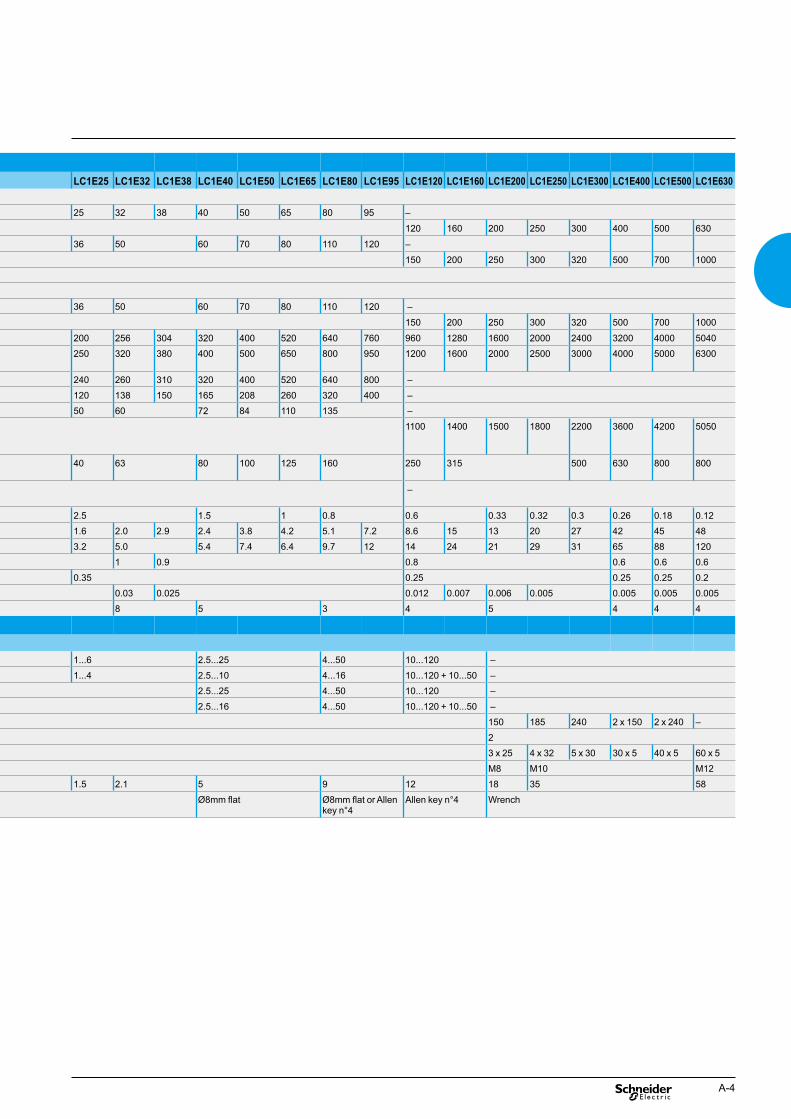
LC1E25 LC1E32 LC1E38 LC1E40 LC1E50 LC1E65 LC1E80 LC1E95 LC1E120 LC1E160 LC1E200 LC1E250 LC1E300 LC1E400 LC1E500 LC1E630
25 32 38 40 50 65 80 95 –
120 160 200 250 300 400 500 630
36 50 60 70 80 110 120 –
150 200 250 300 320 500 700 1000
36 50 60 70 80 110 120 –
150 200 250 300 320 500 700 1000
200 256 304 320 400 520 640 760 960 1280 1600 2000 2400 3200 4000 5040
250 320 380 400 500 650 800 950 1200 1600 2000 2500 3000 4000 5000 6300
240 260 310 320 400 520 640 800 –
120 138 150 165 208 260 320 400 –
50 60 72 84 110 135 –
1100 1400 1500 1800 2200 3600 4200 5050
40 63 80 100 125 160 250 315 500 630 800 800
–
2.5 1.5 1 0.8 0.6 0.33 0.32 0.3 0.26 0.18 0.12
1.6 2.0 2.9 2.4 3.8 4.2 5.1 7.2 8.6 15 13 20 27 42 45 48
3.2 5.0 5.4 7.4 6.4 9.7 12 14 24 21 29 31 65 88 120
1 0.9 0.8 0.6 0.6 0.6
0.35 0.25 0.25 0.25 0.2
0.03 0.025 0.012 0.007 0.006 0.005 0.005 0.005 0.005
8 5 3 4 5 4 4 4
1...6 2.5...25 4...50 10...120 –
1...4 2.5...10 4...16 10...120 + 10...50 –
2.5...25 4...50 10...120 –
2.5...16 4...50 10...120 + 10...50 –
150 185 240 2 x 150 2 x 240 –
2
3 x 25 4 x 32 5 x 30 30 x 5 40 x 5 60 x 5
M8 M10 M12
1.5 2.1 5 9 12 18 35 58
Ø8mm flat Ø8mm flat or Allen key n°4
Allen key n°4 Wrench
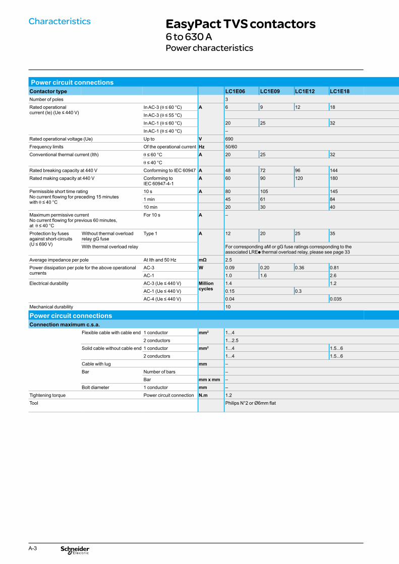
Characteristics EasyPact TVS contactors6 to 630 A Power characteristics
Power circuit connections Contactor type LC1E06 LC1E09 LC1E12 LC1E18 Number of poles 3
Rated operational current (Ie) (Ue ≤ 440 V)
In AC-3 (q ≤ 60 °C) A 6 9 12 18
In AC-3 (q ≤ 55 °C)
In AC-1 (q ≤ 60 °C) 20 25 32
In AC-1 (q ≤ 40 °C) –
Rated operational voltage (Ue) Up to V 690
Frequency limits Of the operational current Hz 50/60
Conventional thermal current (Ith) q ≤ 60 °C A 20 25 32
q ≤ 40 °C
Rated breaking capacity at 440 V Conforming to IEC 60947 A 48 72 96 144
Rated making capacity at 440 V Conforming to IEC 60947-4-1
A 60 90 120 180
Permissible short time rating No current flowing for preceding 15 minutes with q ≤ 40 °C
10 s A 80 105 145
1 min 45 61 84
10 min 20 30 40
Maximum permissive current No current flowing for previous 60 minutes, at q ≤ 40 °C
For 10 s A –
Protection by fuses against short-circuits (U ≤ 690 V)
Without thermal overload relay gG fuse
Type 1 A 12 20 25 35
With thermal overload relay For corresponding aM or gG fuse ratings corresponding to the associated LREp thermal overload relay, please see page 33
Average impedance per pole At Ith and 50 Hz mΩ 2.5
Power dissipation per pole for the above operational currents
AC-3 W 0.09 0.20 0.36 0.81
AC-1 1.0 1.6 2.6
Electrical durability AC-3 (Ue ≤ 440 V) Million cycles
1.4 1.2
AC-1 (Ue ≤ 440 V) 0.15 0.3
AC-4 (Ue ≤ 440 V) 0.04 0.035
Mechanical durability 10
Power circuit connections Connection maximum c.s.a.
Flexible cable with cable end 1 conductor mm2 1...4
2 conductors 1...2.5
Solid cable without cable end 1 conductor mm2 1...4 1.5...6
2 conductors 1...4 1.5...6
Cable with lug mm –
Bar Number of bars –
Bar mm x mm –
Bolt diameter 1 conductor mm –
Tightening torque Power circuit connection N.m 1.2
Tool Philips N°2 or Ø6mm flat
A-3
Power circuit connections Contactor type LC1E06 LC1E09 LC1E12 LC1E18Number of poles 3
Rated operational current (Ie) (Ue ≤ 440 V)
In AC-3 (q ≤ 60 °C) A 6 9 12 18
In AC-3 (q ≤ 55 °C)
In AC-1 (q ≤ 60 °C) 20 25 32
In AC-1 (q ≤ 40 °C) –
Rated operational voltage (Ue) Up to V 690
Frequency limits Of the operational current Hz 50/60
Conventional thermal current (Ith) q ≤ 60 °C A 20 25 32
q ≤ 40 °C
Rated breaking capacity at 440 V Conforming to IEC 60947 A 48 72 96 144
Rated making capacity at 440 V Conforming to IEC 60947-4-1
A 60 90 120 180
Permissible short time rating No current flowing for preceding 15 minutes with q ≤ 40 °C
10 s A 80 105 145
1 min 45 61 84
10 min 20 30 40
Maximum permissive currentNo current flowing for previous 60 minutes, at q ≤ 40 °C
For 10 s A –
Protection by fusesagainst short-circuits (U ≤ 690 V)
Without thermal overload relay gG fuse
Type 1 A 12 20 25 35
With thermal overload relay For corresponding aM or gG fuse ratings corresponding to the associated LREp thermal overload relay, please see page 33
Average impedance per pole At Ith and 50 Hz mΩ 2.5
Power dissipation per pole for the above operationalcurrents
AC-3 W 0.09 0.20 0.36 0.81
AC-1 1.0 1.6 2.6
Electrical durability AC-3 (Ue ≤ 440 V) Million cycles
1.4 1.2
AC-1 (Ue ≤ 440 V) 0.15 0.3
AC-4 (Ue ≤ 440 V) 0.04 0.035
Mechanical durability 10
Power circuit connectionsConnection maximum c.s.a.
Flexible cable with cable end 1 conductor mm2 1...4
2 conductors 1...2.5
Solid cable without cable end 1 conductor mm2 1...4 1.5...6
2 conductors 1...4 1.5...6
Cable with lug mm –
Bar Number of bars –
Bar mm x mm –
Bolt diameter 1 conductor mm –
Tightening torque Power circuit connection N.m 1.2
Tool Philips N°2 or Ø6mm flat
LC1E25 LC1E32 LC1E38 LC1E40 LC1E50 LC1E65 LC1E80 LC1E95 LC1E120 LC1E160 LC1E200 LC1E250 LC1E300 LC1E400 LC1E500 LC1E630
25 32 38 40 50 65 80 95 –
120 160 200 250 300 400 500 630
36 50 60 70 80 110 120 –
150 200 250 300 320 500 700 1000
36 50 60 70 80 110 120 –
150 200 250 300 320 500 700 1000
200 256 304 320 400 520 640 760 960 1280 1600 2000 2400 3200 4000 5040
250 320 380 400 500 650 800 950 1200 1600 2000 2500 3000 4000 5000 6300
240 260 310 320 400 520 640 800 –
120 138 150 165 208 260 320 400 –
50 60 72 84 110 135 –
1100 1400 1500 1800 2200 3600 4200 5050
40 63 80 100 125 160 250 315 500 630 800 800
–
2.5 1.5 1 0.8 0.6 0.33 0.32 0.3 0.26 0.18 0.12
1.6 2.0 2.9 2.4 3.8 4.2 5.1 7.2 8.6 15 13 20 27 42 45 48
3.2 5.0 5.4 7.4 6.4 9.7 12 14 24 21 29 31 65 88 120
1 0.9 0.8 0.6 0.6 0.6
0.35 0.25 0.25 0.25 0.2
0.03 0.025 0.012 0.007 0.006 0.005 0.005 0.005 0.005
8 5 3 4 5 4 4 4
1...6 2.5...25 4...50 10...120 –
1...4 2.5...10 4...16 10...120 + 10...50 –
2.5...25 4...50 10...120 –
2.5...16 4...50 10...120 + 10...50 –
150 185 240 2 x 150 2 x 240 –
2
3 x 25 4 x 32 5 x 30 30 x 5 40 x 5 60 x 5
M8 M10 M12
1.5 2.1 5 9 12 18 35 58
Ø8mm flat Ø8mm flat or Allen key n°4
Allen key n°4 Wrench
A-4

LC1E25 LC1E32 LC1E38 LC1E40 LC1E50 LC1E65 LC1E80 LC1E95 LC1E120 LC1E160 LC1E200 LC1E250 LC1E300 LC1E400 LC1E500 LC1E630 24...440 according coil voltage code
–
–
95 160 200 300 805 650 1075 1100 1650
0.8 0.9 0.3 0.9 0.9 0.9 0.9
8.3 15 20 22 55 10 15 18 22
0.3 0.9 0.3 0.9 0.9 0.9 0.9
95 140 220 300 970 650 1075 1100 1650
0.8 0.9 0.3 0.9 0.9 0.9 0.9
8.3 13 22 22 66 10 15 18 22
0.9 0.3 0.9 0.9 0.9 0.9
6...10 3...8 18...24 8 14 18 20
20...26 20...35 20...50 20...35 40...65 40…75 40…80
8...12 6...20 6...20 7...15 100...170 100…170 100…200
1 0.9 0.8 0.6 0.6 0.6
0.4 0.25 0.25 0.2
8 5 3 4 4 4
1200 –
1200 2400 1200
1...2.5 1...4 1/4 1/4 1/4
1...2.5 1/4 1/4 1/4
1/2.5 1/2.5 1/2.5
1...2.5 1...4 1/4 1/4 1/4
1.2 1.2 1.2 1.2 1.2
Characteristics EasyPact TVS contactors6 to 630 A Control circuit: coil characteristics Built in auxiliary contact
Control circuit: coil characteristics with a.c. supply Contactor type LC1E06 LC1E09 LC1E12 LC1E18
Rated control circuit voltage (Uc) 50/60 Hz V 24...440 according coil voltage code
Control voltage limits (q ≤ 55 °C)
50 Hz or 60 Hz coils Operational 0.85...1.1 Uc
Drop-out 0.3...0.6 Uc
Average consumption at 20°C and at Uc
a 50 Hz coils Inrush coil VA 95
cos j 0.75
Sealed coil VA 8.5
cos j 0.3
a 60 Hz coils Inrush coil VA 95
cos j 0.75
Sealed coil VA 8.5
cos j 0.3
Heat dissipation W 2.3
Operating time Closing "C" ms 12...22
Opening "O" 4...19
Electrical durability (AC-3) AC-3 (Ue ≤ 440 V) In millions of operating cycles
1.2...1.4
AC-1 (Ue ≤ 440 V) –
Mechanical durability at Uc 10
Maximum operating rate at ambiant temperature ≤ 60 °C
In operatingcycles per hour
1800
Maximum operating rate at ambiant temperature ≤ 55 °C
–
Control circuit connections Connection maximum c.s.a.
Flexible cable without cable end
1 or 2 conductors mm2 1...4
Flexible cable with cable end
1 conductor mm2 1...4
2 conductors 1...2.5
Solid cable without cable end
1 or 2 conductors mm2 1...4
Tightening torque N.m 1.7
Screwdriver Philips N° 2 - Ø6 mm flat
Built in auxiliary contact Contacts conforming to IEC 60947-5-1 LC1E06...E38: contactor's own 1NO or 1NC
LC1E40...E160: contactor's own 1NO and 1NC
Rated operational voltage (Ue) Up to V 690
Rated insulation voltage (Ui) Conforming to IEC 60947-1 690
Conventional thermal current (Ith) Ambient air temperature ≤ 60 °C A 10
Operating current frequency Hz 50/60 Hz
Minimum switching capacity l = 10-8
U min V 17
I min mA 5
Short-circuit protection Conforming to IEC 60947-5-1 gG fuse: 10 A
Raked making capacity Conforming to IEC 60947-5-1 A a: 140
Short-time rating Permissible for 1 s A 100
500 ms 120
100 ms 140
Insulation resistance MΩ >10
Non-overlap time Guaranteed between N/C and N/O contacts
ms 1.5 on energisation and on de-energisation
A-5

Control circuit: coil characteristics with a.c. supplyContactor type LC1E06 LC1E09 LC1E12 LC1E18
Rated control circuit voltage (Uc) 50/60 Hz V 24...440 according coil voltage code
Control voltage limits (q ≤ 55 °C)
50 Hz or 60 Hz coils Operational 0.85...1.1 Uc
Drop-out 0.3...0.6 Uc
Average consumption at 20°C and at Uc
a 50 Hz coils Inrush coil VA 95
cos j 0.75
Sealed coil VA 8.5
cos j 0.3
a 60 Hz coils Inrush coil VA 95
cos j 0.75
Sealed coil VA 8.5
cos j 0.3
Heat dissipation W 2.3
Operating time Closing "C" ms 12...22
Opening "O" 4...19
Electrical durability (AC-3) AC-3 (Ue ≤ 440 V) In millions of operating cycles
1.2...1.4
AC-1 (Ue ≤ 440 V) –
Mechanical durability at Uc 10
Maximum operating rate at ambiant temperature ≤ 60 °C
In operating cycles per hour
1800
Maximum operating rate at ambiant temperature ≤ 55 °C
–
Control circuit connectionsConnection maximum c.s.a.
Flexible cable without cable end
1 or 2 conductors mm2 1...4
Flexible cable with cable end
1 conductor mm2 1...4
2 conductors 1...2.5
Solid cable without cable end
1 or 2 conductors mm2 1...4
Tightening torque N.m 1.7
Screwdriver Philips N° 2 - Ø6 mm flat
Built in auxiliary contactContacts conforming to IEC 60947-5-1 LC1E06...E38: contactor's own 1NO or 1NC
LC1E40...E160: contactor's own 1NO and 1NC
Rated operational voltage (Ue) Up to V 690
Rated insulation voltage (Ui) Conforming to IEC 60947-1 690
Conventional thermal current (Ith) Ambient air temperature ≤ 60 °C A 10
Operating current frequency Hz 50/60 Hz
Minimum switching capacity l = 10-8
U min V 17
I min mA 5
Short-circuit protection Conforming to IEC 60947-5-1 gG fuse: 10 A
Raked making capacity Conforming to IEC 60947-5-1 A a: 140
Short-time rating Permissible for 1 s A 100
500 ms 120
100 ms 140
Insulation resistance MΩ >10
Non-overlap time Guaranteed between N/C and N/O contacts
ms 1.5 on energisation and on de-energisation
LC1E25 LC1E32 LC1E38 LC1E40 LC1E50 LC1E65 LC1E80 LC1E95 LC1E120 LC1E160 LC1E200 LC1E250 LC1E300 LC1E400 LC1E500 LC1E630 24...440 according coil voltage code
–
–
95 160 200 300 805 650 1075 1100 1650
0.8 0.9 0.3 0.9 0.9 0.9 0.9
8.3 15 20 22 55 10 15 18 22
0.3 0.9 0.3 0.9 0.9 0.9 0.9
95 140 220 300 970 650 1075 1100 1650
0.8 0.9 0.3 0.9 0.9 0.9 0.9
8.3 13 22 22 66 10 15 18 22
0.9 0.3 0.9 0.9 0.9 0.9
6...10 3...8 18...24 8 14 18 20
20...26 20...35 20...50 20...35 40...65 40…75 40…80
8...12 6...20 6...20 7...15 100...170 100…170 100…200
1 0.9 0.8 0.6 0.6 0.6
0.4 0.25 0.25 0.2
8 5 3 4 4 4
1200 –
1200 2400 1200
1...2.5 1...4 1/4 1/4 1/4
1...2.5 1/4 1/4 1/4
1/2.5 1/2.5 1/2.5
1...2.5 1...4 1/4 1/4 1/4
1.2 1.2 1.2 1.2 1.2
A-6
LC1E40...E65 LC1E80...E95 LC1E120...E160 LC1E200...E300 LC1E400 LC1E500 LC1E630
8
IEC 60947-4-1
IP00
–
6gn 9gn 6gn
7 gn 15gn
1.5gn 2gn
5gn 4gn
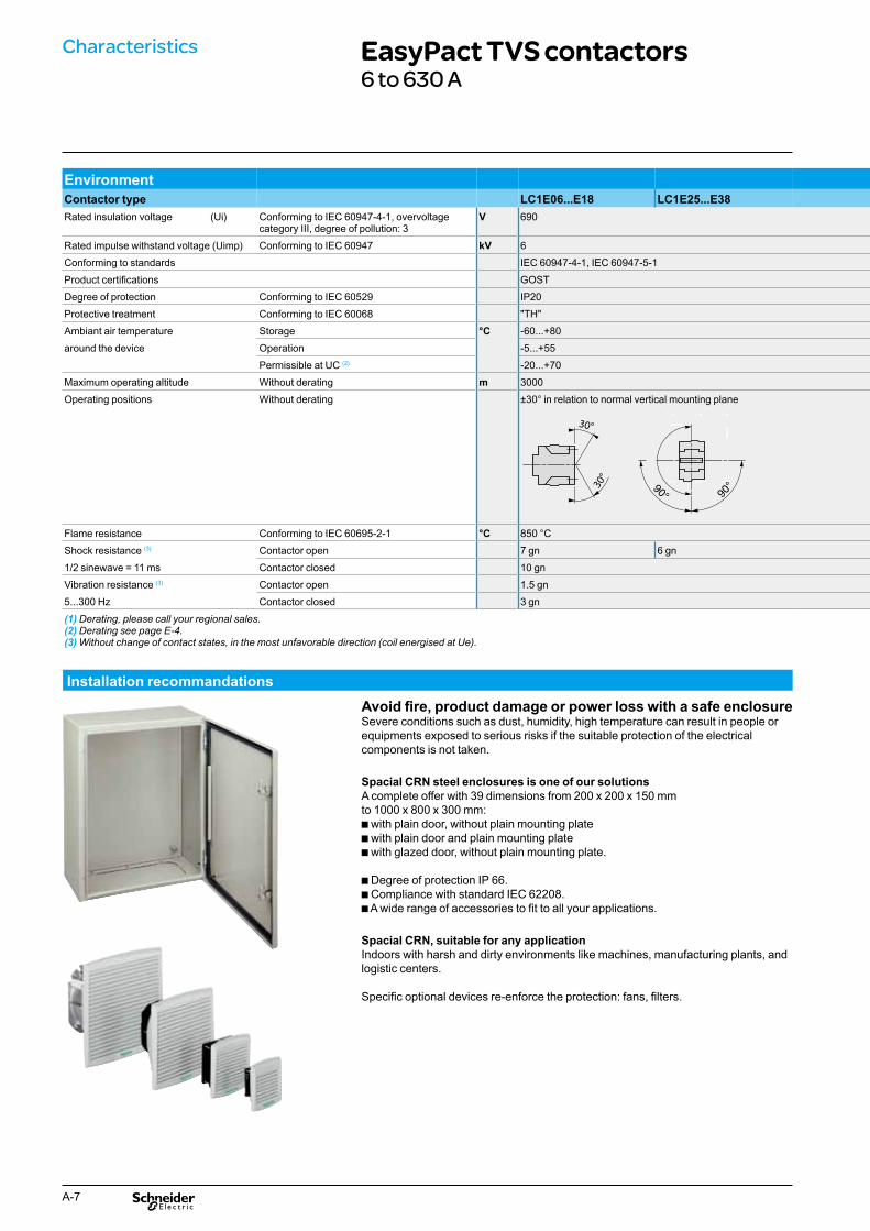
Characteristics EasyPact TVS contactors6 to 630 A
0°
Installation recommandations
Environment
81
Avoid fire, product damage or power loss with a safe enclosure Severe conditions such as dust, humidity, high temperature can result in people or equipments exposed to serious risks if the suitable protection of the electrical
Spacial CRN steel enclosures is one of our solutions A complete offer with 39 dimensions from 200 x 200 x 150 mm
bA wide range of accessories to fit to all your applications.
Indoors with harsh and dirty environments like machines, manufacturing plants, and
Specific optional devices re-enforce the protection: fans, filters.
Contactor type LC1E06...E18 LC1E25...E38 Rated insulation voltage (Ui) Conforming to IEC 60947-4-1, overvoltage
category III, degree of pollution: 3 V 690
Rated impulse withstand voltage (Uimp) Conforming to IEC 60947 kV 6
Conforming to standards IEC 60947-4-1, IEC 60947-5-1
Product certifications GOST
Degree of protection Conforming to IEC 60529 IP20
Protective treatment Conforming to IEC 60068 "TH"
Ambiant air temperature Storage °C -60...+80
around the device Operation -5...+55
Permissible at UC (2) -20...+70
Maximum operating altitude Without derating m 3000
Operating positions Without derating ±30° in relation to normal vertical mounting plane
Flame resistance Conforming to IEC 60695-2-1 °C 850 °C
Shock resistance (3) Contactor open 7 gn 6 gn
1/2 sinewave = 11 ms Contactor closed 10 gn
Vibration resistance (3) Contactor open 1.5 gn
5...300 Hz Contactor closed 3 gn
90°90°
(1) Derating, please call your regional sales. (2) Derating see page E-4. (3) Without change of contact states, in the most unfavorable direction (coil energised at Ue).
components is not taken.
to 1000 x 800 x 300 mm:b with plain door, without plain mounting plateb with plain door and plain mounting plateb with glazed door, without plain mounting plate.
b Degree of protection IP 66.b Compliance with standard IEC 62208.
Spacial CRN, suitable for any application
logistic centers.
A-7

EnvironmentContactor type LC1E06...E18 LC1E25...E38Rated insulation voltage (Ui) Conforming to IEC 60947-4-1, overvoltage
category III, degree of pollution: 3V 690
Rated impulse withstand voltage (Uimp) Conforming to IEC 60947 kV 6
Conforming to standards IEC 60947-4-1, IEC 60947-5-1
Product certifications GOST
Degree of protection Conforming to IEC 60529 IP20
Protective treatment Conforming to IEC 60068 "TH"
Ambiant air temperature Storage °C -60...+80
around the device Operation -5...+55
Permissible at UC (2) -20...+70
Maximum operating altitude Without derating m 3000
Operating positions Without derating ±30° in relation to normal vertical mounting plane
Flame resistance Conforming to IEC 60695-2-1 °C 850 °C
Shock resistance (3) Contactor open 7 gn 6 gn
1/2 sinewave = 11 ms Contactor closed 10 gn
Vibration resistance (3) Contactor open 1.5 gn
5...300 Hz Contactor closed 3 gn
(1) Derating, please call your regional sales.(2) Derating see page E-4.(3) Without change of contact states, in the most unfavorable direction (coil energised at Ue).
LC1E40...E65 LC1E80...E95 LC1E120...E160 LC1E200...E300 LC1E400 LC1E500 LC1E630
8
IEC 60947-4-1
IP00
–
30°
90°
6gn 9gn 6gn
7 gn 15gn
1.5gn 2gn
5gn 4gn
A-8

Characteristics EasyPact TVS contactorsEasyPact TVS contactors for motor control up to 335 kW at 400 V, in category AC-3
CPB
1004
15
CPB
1004
21C
PB10
0419
CPB
1004
17
LC1E06
3-pole contactors Standard power ratings of 3-phase motors 50/60 Hz in category AC-3
Rated operationalcurrent in AC-3 440 V up to
Instantaneous auxiliary contacts
Basic reference, to be completed by addingthe control voltage code
Weight
220 V 380 V 230 V 400 V 415 V 500 V 690 V Fixing (1)
kW kW kW kW kW A kg Connection by screw clamp terminals 1.1 2.2 2.2 3 3 6 1 0 LC1E0610pp 0.300
1.1 2.2 2.2 3 3 6 0 1 LC1E0601pp 0.300
2.2 4 4 5.5 5.5 9 1 0 LC1E0910pp 0.300
LC1E65 2.2 4 4 5.5 5.5 9 0 1 LC1E0901pp 0.300
3 5.5 5.5 7.5 7.5 12 1 0 LC1E1210pp 0.300
3 5.5 5.5 7.5 7.5 12 0 1 LC1E1201pp 0.300
4 7.5 9 10 10 18 1 0 LC1E1810pp 0.300
4 7.5 9 10 10 18 0 1 LC1E1801pp 0.300
5.5 11 11 15 15 25 1 0 LC1E2510pp 0.360
5.5 11 11 15 15 25 0 1 LC1E2501pp 0.360
7.5 15 15 18.5 18.5 32 1 0 LC1E3210pp 0.450
7.5 15 15 18.5 18.5 32 0 1 LC1E3201pp 0.450
9 18.5 18.5 18.5 18.5 38 1 0 LC1E3810pp 0.450
9 18.5 18.5 18.5 18.5 38 0 1 LC1E3801pp 0.450
LC1E120 11 18.5 22 22 30 40 1 1 LC1E40pp 0.980
15 22 25/30 30 33 50 1 1 LC1E50pp 0.980
18.5 30 37 37 37 65 1 1 LC1E65pp 0.980
22 37 45 45 45 80 1 1 LC1E80pp 1.520
25 45 45 55 45 95 1 1 LC1E95pp 1.520
37 55 59 75 80 120 1 1 LC1E120pp 2.300
45 75 80 90 100 160 1 1 LC1E160pp 2.300
Connection by bars 55 90 100 110 110 200 0 0 LC1E200pp 4.600
75 132 140 160 160 250 0 0 LC1E250pp 4.700
90 160 160/185 200 220 300 0 0 LC1E300pp 8.500
110 200 220/250 257 280 400 0 0 LC1E400pp 9.1
147 250 280/295 355 335 500 0 0 LC1E500pp 11.35
185 335 375/400 400 450 630 0 0 LC1E630pp 18.6
LC1E300
Control voltage code Volts 24 48 110 220 240 380 415 440
LC1E06-300 50 Hz B5 E5 F5 M5 U5 Q5 N5 R5
60 Hz B6 - F6 M6 - Q6 - R6
LC1E400-630 50/60Hz - E7 F7 M7 U7 Q7 N7 -
Seperate components Auxiliary contact blocks, add-on modules and accessories, see pages 15 to 17.
Coil spare parts For maintenance, each coil can be ordered separatly, see page 18 to 21.
(1) LC1E06 to E65: clip-on mounting on 35 mm 5 rail AM1 DP or screw fixing. LC1E80 to E95: clip-on mounting on 35 mm 5 rail AM1DP or 75 mm 5 rail AM1 DL or screw fixing.LC1E120 and E160: clip-on mounting on 2 x 35 mm 5 rail AM1 DP or screw fixing.
A-9

Accessories for LC1E contactor
Accessories for motor reverse assembly Contactors with screw clamp terminals Using 2 identical contactors Set of power connections Mechanical interlock
Cat. no. Weight Cat. no. Weight kg kg
LAEM1 Mechanical interlock LC1E06...E12 LAEP1 0.020 LAEM1 0.030
LC1E18/E25 LAEP12 0.026 LAEM1 0.030
LC1E32/E38 LAEP2 0.040 LAEM1 0.030
LC1E40...E65 LAEP3 0.230 LAEM1 0.030
LC1E80/E95 LAEP4 0.465 LAEM4 0.095LAEP3
LC1E120/E160 – (DIY) (1) LAEM5 0.300
LC1E200/E250 – (DIY) (1) LAEM6 0.110
LC1E300 – (DIY) (1) LAEM7 0.250
LC1E400 – (DIY) (1) LAEM8 0.14
LC1E500 – (DIY) (1) LAEM9 0.14
LC1E630 – (DIY) (1) LAEM10 0.15
LAEP4 (1) DIY : Do It Yourself.
RC surge suppressor b Effective protection for circuits highly sensitive to "high frequency" interference and transcient generated when the contactor coil is switched off. For use only in cases where the voltage is virtually sinusoidal, i.e. less than 5 % total harmonic distortion. b Voltage limited to 3 Uc max. and oscillating frequency limited to 400 Hz max. b Slight increase in drop-out time (1.2 to 2 times the normal time).
Mounting For use with contactor Cat. no. Weight Rating Type
Va kg
LAEM6/ Screw mounting LC1E06...E95 24...48 LAERCE 0.025
LAEM7 50...127 LAERCG 0.025
110...240 LAERCU 0.025
380...415 LAERCN 0.025
LAERCp
LC1Epp
A-10

Characteristics EasyPact TVS contactorsAccessories for LC1E contactor
Instantaneous auxiliary contact blocks for connection byscrew lamps terminals For use in normal operating environment
Front 1 NO / 1 NC LAEN11 0.035
LAEN22 2 NO LAEN20 0.035
2 NC LAEN02 0.035
2 NO / 2 NC LAEN22 0.060
Clip-on mounting Number of contacts per block
Cat. no. Weight kg
Time delay auxiliary contact blocks for connection by screw clamp terminals 8 A - 690 V
LAETSD Front 1 NO / 1 NC On-delay 1...30 s LAETSD
Clip-on mounting
Number of contacts per block
Time delay Setting range Cat. no. (1) Weight Type kg
(1) For use only LC1E25 to LC1E630.
Instantaneous and time delay contact characteristics Contact block type LAEN11, 20, 02, 22 LAETSD
Number of contacts 2 or 4 2
Rated operational voltage (Ue) Up to V 690
Rated insulation voltage (Ui) Conforming to IEC 60947-5-1 690
Conventional thermal current (Ith) For ambient temperature q ≤ 60 °C
A 8
Frequency of the operational current
Hz 50/60
Minimum switching capacity U min V 17
I min mA 5
Short-circuit protection Conforming to IEC 60947-5-1 A 10
Rated making capacity Conforming to IEC 60947-5-1 Irms a 140
Short-time rating Permissible for 1 s A 100
500 ms 120
100 ms 140
Insulation resistance mΩ > 10
Non-overlap time Guaranteed between NC and NO contacts
ms 1.5 (on energisation and on de-energisation)
Overlap time Guaranteed between LAE N22 N/C and N/O contacts
ms –
Time delay Ambient air temperature for operation
°C – -20...+70
Repeat accuracy – ±2 %
Drift up to 0.5 million operating cycles
– +15 %
Drift depending on ambient air temperature
– 0.25 % per °C
Mechanical durability In millions of operating cycles
10 4
Rated operational power of contacts (Conforming to IEC 60947-5-1)
a.c. supply categories AC14/15 V 24 48 115 230 400 440
1 million operating cycles VA 60 120 280 560 960 1050
3 million operating cycles 16 32 80 160 280 300
10 million operating cycles 4 8 20 4 70 80
A-11
0.060

Accessories for LC1E
Environment Contact block type LAEN11, 20, 02, 22 LAETSD
Conforming to standard IEC 60947-5-1
Product certifications GOST
Protective treatment Conforming to IEC 60068 "TH"
Degree of protection Conforming to IEC 60529 IP20
Ambiant air temperature Storage °C -60...+80
Operation -5...+55
Permissible for operation at Uc -20...+70
Maximum operating altitude Without derating m 3000
Connection by cable Philips N° 2 and Ø 6 mm. Flexible or solid cable with or without cable end
mm2 Min: 1 x 1 Max: 2 x 2.5
Accessories compatibility Contactor Built in
contacts LAENpp LAETSD LAERCp LAEM LAEPp
LC1E06
1 NO or 1NC
1 -
1
1
1
LC1E09
LC1E12
LC1E18
LC1E25
1 or 1
LC1E32
LC1E38
LC1E40
1 NO + 1NC
LC1E50
LC1E65
LC1E80
LC1E95
LC1E120
- DIY (1)
LC1E160
LC1E200
-2 or 0 1 or 1
LC1E250
LC1E300
LC1E400
LC1E500
LC1E630
(1) Do It Yourself.
A-12

Characteristics EasyPact TVS contactorsCoil replacement for EasyPact TVS, LC1E06 to E38
Control circuit voltage Uc
Average resistance at 20 °C ±10 %
Inductance of closed circuit
Cat. no. (1) Average resistance at 20 °C ±10 %
Inductance of closed circuit
Cat. no. (1) Weight
V Ω H 50 Hz Ω H 60 Hz kg
24 8.70 0.24 LAEX1B5 7.80 0.15 LAEX1B6 0.056
48 37.0 1.00 LAEX1E5 - - - 0.056
110 190 4.64 LAEX1F5 170 3.07 LAEX1F6 0.056
220 750 19.7 LAEX1M5 690 11.6 LAEX1M6 0.056
240 890 23.4 LAEX1U5 - - - 0.056
380 2250 58.3 LAEX1Q5 2110 35.4 LAEX1Q6 0.056
415 2610 69.0 LAEX1N5 - - - 0.056
440 2690 78.2 LAEX1R5 2760 50.7 LAEX1R6 0.056
For 3-pole contactors LC1E06...E18 Specifications
Average consumption at 20 °C: b inrush (cos j = 0.75) 50 Hz: 95 VA; 60 Hz: 95 VA b sealed (cos j = 0.3) 50 Hz: 8.5 VA; 60 Hz: 8.5 VA Operating range (q ≤ 55 °C): 0.85...1.1 Uc.
LAEX1pp
For 3-pole contactors LC1E25 Specifications
Average consumption at 20 °C: b inrush (cos j = 0.75) 50 Hz: 70 VA; 60 Hz: 70 VA b sealed (cos j = 0.3) 50 Hz: 7 VA; 60 Hz: 7.5 VA Operating range (q ≤ 55 °C): 0.85...1.1 Uc.
Control circuit voltage Uc
Average resistance at 20 °C ±10 %
Inductance of closed circuit
Cat. no. (1) Average resistance at 20 °C ±10 %
Inductance of closed circuit
Cat. no. (1) Weight
V Ω H 50 Hz Ω H 60 Hz kg
24 5.37 0.21 LAEX12B5 5.37 0.18 LAEX12B6 0.067
48 21.7 0.84 LAEX12E5 - - - 0.067
110 124 4.41 LAEX12F5 124 3.68 LAEX12F6 0.067
220 515 17.6 LAEX12M5 516 14.7 LAEX12M6 0.067
240 562 21.0 LAEX12U5 - - - 0.067
380 1550 52.6 LAEX12Q5 1550 43.8 LAEX12Q6 0.067
415 1690 62.8 LAEX12N5 - - - 0.067
440 1990 70.6 LAEX12R5 1990 58.9 LAEX12R6 0.067
LAEX2pp
For 3-pole contactors LC1E32/E38 Specifications
Average consumption at 20 °C: b inrush (cos j = 0.75) 50 Hz: 70 VA; 60 Hz: 70 VA b sealed (cos j = 0.3) 50 Hz: 7 VA; 60 Hz: 7.5 VA Operating range (q ≤ 55 °C): 0.85...1.1 Uc.
Control circuit voltageUc
Average resistance at 20 °C ±10 %
Inductance of closed circuit
Cat. no. (1) Average resistance at 20 °C ±10 %
Inductance of closed circuit
Cat. no. (1) Weight
V Ω H 50 Hz Ω H 60 Hz kg
24 5.37 0.21 LAEX2B5 5.37 0.18 LAEX2B6 0.073
48 21.7 0.84 LAEX2E5 - - - 0.073
110 124 4.41 LAEX2F5 124 3.68 LAEX2F6 0.073
220 515 17.6 LAEX2M5 516 14.7 LAEX2M6 0.073
240 562 21.0 LAEX2U5 - - - 0.073
380 1550 52.6 LAEX2Q5 1550 43.8 LAEX2Q6 0.073
415 1690 62.8 LAEX2N5 - - - 0.073
440 1990 70.6 LAEX2R5 1990 58.9 LAEX2R6 0.073
(1) The last two digits in the reference represent the voltage code.
A-13
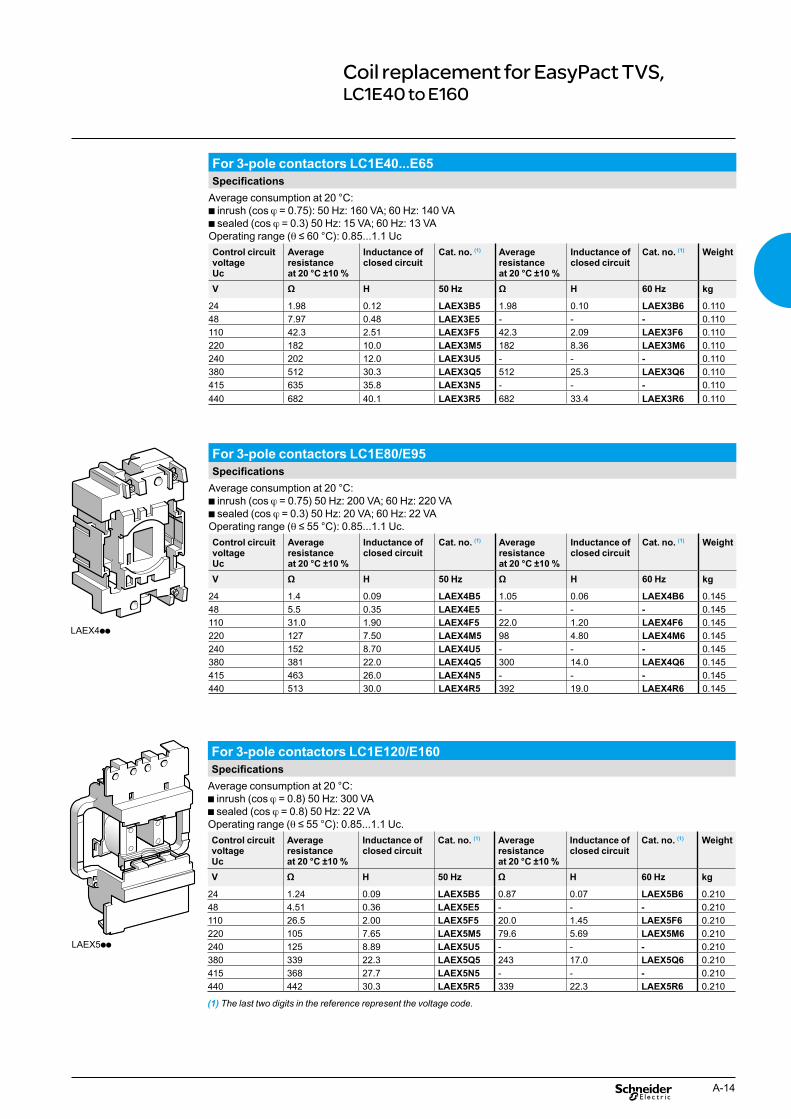
Coil replacement for EasyPact TVS,LC1E40 to E160
For 3-pole contactors LC1E40...E65 Specifications
Average consumption at 20 °C: b inrush (cos j = 0.75): 50 Hz: 160 VA; 60 Hz: 140 VA b sealed (cos j = 0.3) 50 Hz: 15 VA; 60 Hz: 13 VA Operating range (q ≤ 60 °C): 0.85...1.1 Uc
Control circuit voltage Uc
Average resistance at 20 °C ±10 %
Inductance of closed circuit
Cat. no. (1) Average resistance at 20 °C ±10 %
Inductance of closed circuit
Cat. no. (1) Weight
V Ω H 50 Hz Ω H 60 Hz kg
24 1.98 0.12 LAEX3B5 1.98 0.10 LAEX3B6 0.110
48 7.97 0.48 LAEX3E5 - - - 0.110
110 42.3 2.51 LAEX3F5 42.3 2.09 LAEX3F6 0.110
220 182 10.0 LAEX3M5 182 8.36 LAEX3M6 0.110
240 202 12.0 LAEX3U5 - - - 0.110
380 512 30.3 LAEX3Q5 512 25.3 LAEX3Q6 0.110
415 635 35.8 LAEX3N5 - - - 0.110
440 682 40.1 LAEX3R5 682 33.4 LAEX3R6 0.110
LAEX4pp
For 3-pole contactors LC1E80/E95 Specifications
Average consumption at 20 °C: b inrush (cos j = 0.75) 50 Hz: 200 VA; 60 Hz: 220 VA b sealed (cos j = 0.3) 50 Hz: 20 VA; 60 Hz: 22 VA Operating range (q ≤ 55 °C): 0.85...1.1 Uc.
Control circuit voltage Uc
Average resistance at 20 °C ±10 %
Inductance of closed circuit
Cat. no. (1) Average resistance at 20 °C ±10 %
Inductance of closed circuit
Cat. no. (1) Weight
V Ω H 50 Hz Ω H 60 Hz kg
24 1.4 0.09 LAEX4B5 1.05 0.06 LAEX4B6 0.145
48 5.5 0.35 LAEX4E5 - - - 0.145
110 31.0 1.90 LAEX4F5 22.0 1.20 LAEX4F6 0.145
220 127 7.50 LAEX4M5 98 4.80 LAEX4M6 0.145
240 152 8.70 LAEX4U5 - - - 0.145
380 381 22.0 LAEX4Q5 300 14.0 LAEX4Q6 0.145
415 463 26.0 LAEX4N5 - - - 0.145
440 513 30.0 LAEX4R5 392 19.0 LAEX4R6 0.145
LAEX5pp
For 3-pole contactors LC1E120/E160 Specifications
Average consumption at 20 °C: b inrush (cos j = 0.8) 50 Hz: 300 VA b sealed (cos j = 0.8) 50 Hz: 22 VA Operating range (q ≤ 55 °C): 0.85...1.1 Uc.
Control circuit voltageUc
Average resistance at 20 °C ±10 %
Inductance of closed circuit
Cat. no. (1) Average resistance at 20 °C ±10 %
Inductance of closed circuit
Cat. no. (1) Weight
V Ω H 50 Hz Ω H 60 Hz kg
24 1.24 0.09 LAEX5B5 0.87 0.07 LAEX5B6 0.210
48 4.51 0.36 LAEX5E5 - - - 0.210
110 26.5 2.00 LAEX5F5 20.0 1.45 LAEX5F6 0.210
220 105 7.65 LAEX5M5 79.6 5.69 LAEX5M6 0.210
240 125 8.89 LAEX5U5 - - - 0.210
380 339 22.3 LAEX5Q5 243 17.0 LAEX5Q6 0.210
415 368 27.7 LAEX5N5 - - - 0.210
440 442 30.3 LAEX5R5 339 22.3 LAEX5R6 0.210
(1) The last two digits in the reference represent the voltage code.
A-14

LAEX6pp
LAEX7pp
Characteristics EasyPact TVS contactorsCoil replacement for EasyPact TVS, LC1E200 to E300
For 3-pole contactors LC1E200...E250 Specifications
Average consumption at 20 °C: b inrush (cos j = 0.9) 50 Hz: 805 VA; 60 Hz: 970 VAb sealed (cos j = 0.3) 50 Hz: 55 VA; 60 Hz: 66 VAHeat dissipation: 18...24 W. Operating time à Uc: closing = 20...35 ms, opening = 7...15 ms.
Control circuit voltage Uc
Average resistance at 20 °C ±10 %
Inductance of closed circuit
Cat. no. (1) Average resistance at 20 °C ±10 %
Inductance of closed circuit
Cat. no. (1) Weight
V Ω H 50 Hz Ω H 60 Hz kg
24 0.18 0.03 LAEX6B5 0.13 0.02 LAEX6B6 0.510
48 0.71 0.12 LAEX6E5 - - - 0.510
110 4.2 0.65 LAEX6F5 2.7 0.44 LAEX6F6 0.510
220 17 2.59 LAEX6M5 11.1 1.80 LAEX6M6 0.510
240 20 3.09 LAEX6U5 - - - 0.510
380 51.3 7.8 LAEX6Q5 34 5.3 LAEX6Q6 0.510
415 62.3 9.1 LAEX6N5 - - - 0.510
440 62.3 9.1 LAEX6R5 43.5 6.9 LAEX6R6 0.510
LAEX6pp
LAEX7pp
For 3-pole contactors LC1E300 Specifications
Average consumption at 20 °C: b inrush (cos j = 0.9) 50 Hz or 60 Hz: 650 VAb sealed (cos j = 0.3) 50 Hz or 60 Hz: 10 VA.Heat dissipation: 8 W.Operating time à Uc: closing = 40...65 ms, opening = 100...170 ms.Operate on networks with harmonic numbers ≤ 7. Operating cycles/hour (q ≤ 55 °C): ≤ 2400
Control circuit voltage Uc
Average resistance at 20 °C ±10 %
Inductance of closed circuit
Cat. no. (1) Average resistance at 20 °C ±10 %
Inductance of closed circuit
Cat. no. (1) Weight
V Ω H 50 Hz Ω H 60 Hz kg
24 20 (2) LAEX7B5 20 (2) LAEX7B6 0.770
48 67 (2) LAEX7E5 - - - 0.770
110 440 (2) LAEX7F5 440 (2) LAEX7F6 0.770
220 1578 (2) LAEX7M5 1578 (2) LAEX7M6 0.770
240 1968 (2) LAEX7U5 - - - 0.770
380 4631 (2) LAEX7Q5 4631 (2) LAEX7Q6 0.770
415 4631 (2) LAEX7N5 - - - 0.770
440 6731 (2) LAEX7R5 6731 (2) LAEX7R6 0.770
(1) The last two digits in the reference represent the voltage code. (2) Please consult your Regional Sales Office.
A-15
CD
B50
0401
CD
B50
0402
CD
B50
0403
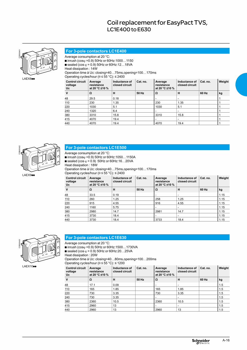
Control circuit voltageUc
Average resistance at 20 °C ±10 %
Inductance of closed circuit
Cat. no. Average resistance at 20 °C ±10 %
Inductance of closed circuit
Cat. no. Weight
V Ω H 50 Hz Ω H 60 Hz kg
48 33.5 0.19 - - 1.15
110 260 1.25 258 1.25 1.15
220 915 4.55 916 4.55 1.15
240 1160 5.75 - - 1.15
380 2980 14.7 2981 14.7 1.15
415 3730 18.4 - - 1.15
440 3730 18.4 3733 18.4 1.15
Control circuit voltage Uc
Average resistance at 20 °C ±10 %
Inductance of closed circuit
Cat. no. Average resistance at 20 °C ±10 %
Inductance of closed circuit
Cat. no. Weight
V Ω H 50 Hz Ω H 60 Hz kg
48 17.1 0.09 - - 1.5
110 165 1.85 165 1.85 1.5
220 730 3.35 730 3.35 1.5
240 730 3.35 - - 1.5
380 2360 10.5 2360 10.5 1.5
415 2960 13 - - 1.5
440 2960 13 2960 13 1.5
Control circuit voltage Uc
Average resistance at 20 °C ±10 %
Inductance of closed circuit
Cat. no. Average resistance at 20 °C ±10 %
Inductance of closed circuit
Cat. no. Weight
V Ω H 50 Hz Ω H 60 Hz kg
48 29.5 0.18 - - 1
110 230 1.35 230 1.35 1
220 1030 5.1 1030 5.1 1
240 1320 6.4 - - 1
380 3310 15.8 3310 15.8 1
415 4070 19.4 - - 1
440 4070 19.4 4070 19.4 1
Coil replacement for EasyPact TVS, LC1E400 to E630
CD
B500
403
CD
B500
402
CD
B500
401 For 3-pole contactors LC1E400
Average consumption at 20 °C: b inrush (cosj =0.9) 50Hz or 60Hz:1000…1150 b sealed (cos j = 0.9) 50Hz or 60Hz:12…18VA Heat dissipation : 14W Operation time à Uc: closing=40…75ms,opening=100…170ms Operating cycles/hour (q ≤ 55 °C): ≤ 2400
LAEX8pp
For 3-pole contactors LC1E500 Average consumption at 20 °C: b inrush (cosj =0.9) 50Hz or 60Hz:1050…1150A b sealed (cos j = 0.9) 50Hz or 60Hz:16…20VA Heat dissipation : 18W Operation time à Uc: closing=40…75ms,opening=100…170ms Operating cycles/hour (q ≤ 55 °C): ≤ 2400
LAEX9pp
For 3-pole contactors LC1E630 Average consumption at 20 °C: b inrush (cosj =0.9) 50Hz or 60Hz:1500…1730VA b sealed (cos j = 0.9) 50Hz or 60Hz:20…25VA Heat dissipation : 20W Operation time à Uc: closing=40…80ms,opening=100…200ms Operating cycles/hour (q ≤ 55 °C): ≤ 1200
LAEX10pp
A-16
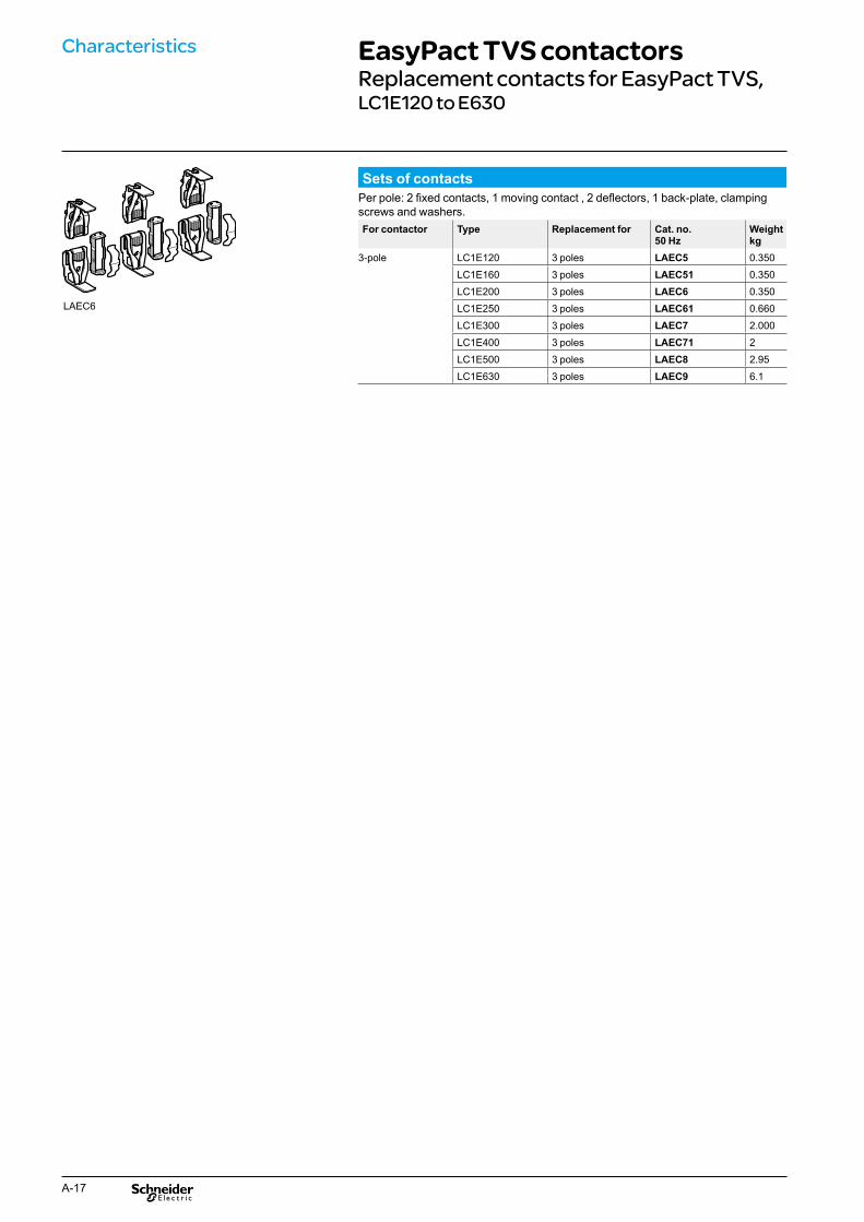
For contactor Type Replacement for Cat. no. 50 Hz
Weight kg
3-pole LC1E120 3 poles LAEC5 0.350
LC1E160 3 poles LAEC51 0.350
LC1E200 3 poles LAEC6 0.350
LC1E250 3 poles LAEC61 0.660
LC1E300 3 poles LAEC7 2.000
LC1E400 3 poles LAEC71 2
LC1E500 3 poles LAEC8 2.95
LC1E630 3 poles LAEC9 6.1
Characteristics EasyPact TVS contactorsReplacement contacts for EasyPact TVS, LC1E120 to E630
Sets of contacts Per pole: 2 fixed contacts, 1 moving contact , 2 deflectors, 1 back-plate, clamping screws and washers.
LAEC6
A-17

Dimensions and mouting EasyPact TVS contactorsLC1E06 to E95
LC1E06...E25 LC1E32/38
LC1 E06...E18 E25 LC1 E32/38
c2
c1
90
LAERCp LAERCp
c2 c1
c 80 85 c 86
c1 with LAEN 113 118 c1 with LAEN 120
c2 with LAETSD - 136 c2 with LAETSD 138
LC1E06...E25 LC1E32/38 2 x Ø4.8
50
C G
2 x Ø4.5 2 x Ø4.5
60/7
0C G
LC1 E06 E09 E12 E18 E25 LC1 E32/38 c 80 80 80 80 85 c 86
G 35 35 35 35 35 G 40
LC1E40...E65 LC1E80/95
LC1 E40...E65 LC1 E80/95
LAERCp
c2
LAERCp
c2
a 75 a 85
b1 with LAERCp 135 b1 with LAERCp 135
c 114 c 121
c1 with LAENp 147 c1 with LAENp 153
c2 with LAETSD 165 c2 with LAETSD 171
2 x LC1E06...E65 with LAEM1 2 x LC1E80/95 with LAEM4
LC1 E06...25 E32...38 E40...65
b 184121
127
a 74 84 127
b 104 126 164
c 80 86 114
A-18
c
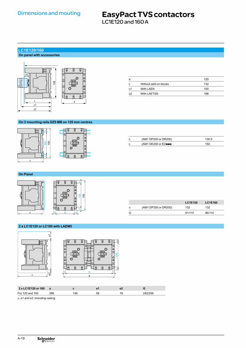
Dimensions and mouting EasyPact TVS contactorsLC1E120 and 160 A
LC1E120/160 On panel with accessories
158
c a c1
c2
10
a 120
c Without add-on blocks 132
c1 With LAEN 150
c2 With LAETSD 168
On 2 mounting rails DZ5 MB on 120 mm centres
100
==
158
c (AM1 DP200 or DR200) 134.5
c (AM1 DE200 or EDppp) 150
On Panel
130
==
158
c G= =
LC1E120 LC1E160 c (AM1 DP200 or DR200) 132 132
G 91/110 96/110
2 x LC1E120 or LC160 with LAEM5
2 x LC1E120 or 160 a c e1 e2 G
158
e1e2c
G
a
= =
130
==
For 120 and 160 266 148 56 18 242/256
c, e1 and e2: including cabing
A-19
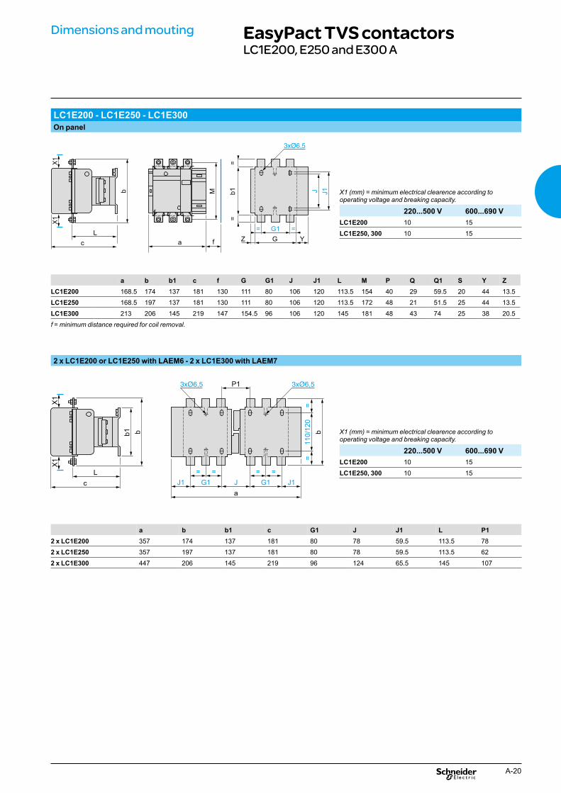
Dimensions and mouting EasyPact TVS contactorsLC1E200, E250 and E300 A
LC1E200 - LC1E250 - LC1E300 On panel
J J1b1
==
G1
GZ
= =
Y L
c
b
X1
X1
f
Mf
a
X1 (mm) = minimum electrical clearence according to operating voltage and breaking capacity.
220...500 V 600...690 V LC1E200 10 15
LC1E250, 300 10 15
a b b1 c f G G1 J J1 L M P Q Q1 S Y Z LC1E200 168.5 174 137 181 130 111 80 106 120 113.5 154 40 29 59.5 20 44 13.5
LC1E250 168.5 197 137 181 130 111 80 106 120 113.5 172 48 21 51.5 25 44 13.5
LC1E300 213 206 145 219 147 154.5 96 106 120 145 181 48 43 74 25 38 20.5
f = minimum distance required for coil removal.
2 x LC1E200 or LC1E250 with LAEM6 - 2 x LC1E300 with LAEM7
110/120
==
=
G1 J1
==
G1
=
J1 J
a
b
P1
L
c
bb1
X1
X1
X1 (mm) = minimum electrical clearence according to operating voltage and breaking capacity.
220...500 V 600...690 V LC1E200 10 15
LC1E250, 300 10 15
a b b1 c G1 J J1 L P1 2 x LC1E200 357 174 137 181 80 78 59.5 113.5 78
2 x LC1E250 357 197 137 181 80 78 59.5 113.5 62
2 x LC1E300 447 206 145 219 96 124 65.5 145 107
A-20
CD
B500
404
CD
B500
405
CD
B500
406
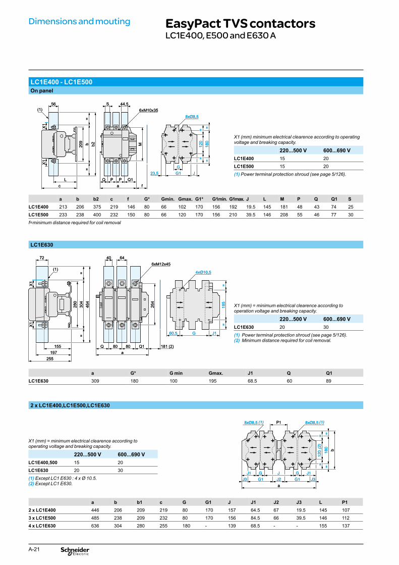
Dimensions and mouting EasyPact TVS contactorsLC1E400, E500 and E630 A
LC1E400 - LC1E500 On panel
5656 SS 44,544,5(1)(1)
L
c
= b
= b220
9
X1
X1
Lc
=b
=b220
9
X1
X1
23,5
Q1
a
PQ P
f
M
6xM10x35
23,5Q1
aPQ P
f
M
6xM10x35
G
G1 J
120
==
180
==
GG1 J
120
==
180
==
X1 (mm) minimum electrical clearence according to operating voltage and breaking capacity.
220...500 V 600...690 V LC1E400 15 20
LC1E500 15 20
(1) Power terminal protection shroud (see page 5/126).
a b b2 c f G* Gmin. Gmax. G1* G1min. G1max. J L M P Q Q1 S LC1E400 213 206 375 219 146 80 66 102 170 156 192 19.5 145 181 48 43 74
LC1E500 233 238 400 232 150 80 66 120 170 156 210 39.5 146 208 55 46 77 30
f=minimum distance required for coil removal
LC1E630
6464404072726xM12x456xM12x45
155
= 30
4 =
197 255
280
X1
464
X1
(1)
155
=30
4=
197255
280
X1
464
X1
(1)
Q1 a
80Q 08
264
181 (2)Q1a
80Q 08
264
181 (2)
185
= 18
5=
J1
=
G60,5 G
=
J160,5
X1 (mm) = minimum electrical clearence according to operation voltage and breaking capacity.
220...500 V 600...690 V LC1E630 20 30
(1) Power terminal protection shroud (see page 5/126). (2) Minimum distance required for coil removal.
a G* G min Gmax. J1 Q Q1 LC1E630 309 180 100 195 68.5 60 89
2 x LC1E400,LC1E500,LC1E630
X1 (mm) = minimum electrical clearence according to operating voltage and breaking capacity.
220...500 V 600...690 V LC1E400,500 15 20
LC1E630 20 30
(1) Except LC1 E630 : 4 x Ø 10.5. (2) Except LC1 E630.
G
G1 J3
120 (2)
==
180
==
b
GJ1 J1
J2
J
G1J3
P1
a
(1)(1)
GG1 J3
120(2)
==
180
==
b
GJ1 J1J2J
G1J3
P1
a
(1)(1)
a b b1 c G G1 J J1 J2 J3 P1 2 x LC1E400 446 206 209 219 80 170 157 64.5 67 19.5 145 107
3 x LC1E500 485 238 209 232 80 170 156 84.5 66 39.5 146
4 x LC1E630 636 304 280 255 180 - 139 68.5 - - 155 137
A-21
25
L
112

54 64
A1
A2
5453
/NO
62
61/N
C
04
03
A2
A1
LC1E 400,500,630
1/L1
2/T1
4/T2
3/L2
6/T3
5/
L3
Schemes EasyPact TVS contactorsLC1E06...630 A
Contactors LC1E06...38 LC1E40...95 LC1E120/160 LC1E200, 250, 300
Reversing contactors 2 x LC1E06...38 2 x LC1E40...95
Horizontaly mounted
2 x LC1E120, 160 2 x LC1E200, 250, 300
Horizontaly mounted
Front mounting add-on contact blocks 1NO + 1NC (LAEN11) 2NO (LAEN20) 2NC (LAEN02) 2NO +2NC (LAEN22)
53/N
O
63/N
O
52
51/N
C
62
61/N
C
54
53/N
O
62
61/N
C
71/N
C
8472
83/N
O
14
A1
A2
12
34
56
L1 L2 L3
12
34
56
U V W
13/N
O
14
13/N
O
A1
A2
22
21/N
C
22
21/N
C
A1
A2
12
34
56
L1 L2 L3
12
34
56
U V W
A1
A2
A1
A2
12
34
56
L1 L2 L3
12
34
56
U V W
A1
A2
22
21/N
C
22
21/N
C
14
A1
A2
12
34
56
L1 L2 L3
12
34
56
U V W
13/N
O
14
13/N
O
A1
A2
22
21/N
C
22
21/N
C
1/L1
2/T1
3/L2
4/T2
13
/NO
14
6/T3
5/
L3A
2 A
1
2/T1
1/
L1
4/T2
3/L2
6/T3
5/
L3
22
21/N
C
A2
A1
2/T1
1/
L1
4/T2
3/L2
6/T3
5/
L3
13/N
O14 22
21
/NC
A2
A1
2/T1
1/
L1
4/T2
3/L2
6/T3
5/
L3
13/N
O14 22
21
/NC
A2
A1
2/T
1 1/
L1
4/T
2 3/
L5
5/L3
6/T
3
A-22

Schemes EasyPact TVS contactorsLC1E06...630 A
Time delay auxiliary contacts On delay 1NO + 1NC (LAETSD)
56
55/N
C
67/N
O68
Mechanical interlock LAEMp
– KM2 – KM1
A1
A2
A1
A2
– KM1 – KM2
A-23

A-24

overload relaysEasyPact TVS Motor starters, contactors & relays up to 630 A
EasyPact TVS thermal
Possible Imax Calibration
TOR Com. Ref
Compatible with Contactor (size 1 & 2) Com. Ref. LC1E06 LC1E09 LC1E12 LC1E18 LC1E25 LC1E32 LC1E38
0.10…0.16 A LRE01 b b b b b b b
0.16…0.25 A LRE02 b b b b b b b
0.25…0.40 A LRE03 b b b b b b b
0.40…0.63 A LRE04 b b b b b b b
0.63…1 A LRE05 b b b b b b b
1…1.6 A LRE06 b b b b b b b
1.6…2.5 A LRE07 b b b b b b b
2.5…4 A LRE08 b b b b b b b
4…6 A LRE10 b b b b b b b
5.5…8 A LRE12 b b b b b b
7…10 A LRE14 b b b b b b
9 …13 A LRE16 b b b b b
12…18 A LRE21 b b b b
16…24 A LRE22 b b b
23…32 A LRE32 b b b
30…38 A LRE35 b
Common characteristics > Class: 10 A. > Operating voltage: max. 690 V AC.
B-1

EasyPact TVS thermal overload relays
TOR Com. Ref Possible Imax Calibration
Compatible with Contactor (size 3 & 4) Com. Ref. LC1E40 LC1E50 LC1E65 LC1E80 LC1E95
LRE322 17…25 A b b b b b
LRE353 23…32 A b b b b b
LRE355 30…40 A b b b b b
LRE357 37…50 A b b b b
LRE359 48…65 A b b b
LRE361 55…70 A b b
LRE363 63…80 A b b
LRE365 80…104 A b
TOR Com. Ref Possible Imax Calibration
Compatible with Contactor (size 5, 6, 7, 8 & 9) Com. Ref. LC1E120 LC1E160 LC1E200 LC1E250 LC1E300 LC1E400 LC1E500 LC1E630
LRE480 51…81A b b v v v v v v
LRE481 62…99A b b v v v v v v
LRE482 84…135A b b v v v v v v
LRE483 124…198A v b v v v v v
LRE484 146…234A v b b b v v
LRE485 174…279A v b b b v v
LRE486 208…333A b b b v v
LRE487 259…414A b b v v
LRE488 321…513A v b v
LRE489 394…630A v b
Note: b means the relay can match with contactor both in electrical and mechanical. v means the relay can match with contactor only in electrical (can not directly mounting).
B-2

Presentation, EasyPact TVS thermal overload description relays
Presentation
LREpp, LRE48p
LRE3pp
6 2
EasyPact TVS thermal overload relays are designed to protect a.c. circuits and motors against: b overloads b phase failure b Long starting time b prolonged stalled rotor condition.
The thermal relay controls permanently the current driven by the motor. When this current exceeds the setting it's auxiliary contacts will change state, causing the motor to stop.
Description
1 Adjustment dial Ir. 2 Test button.
Operation of the Test button allows: - checking of control circuit wiring, - simulation of relay tripping (actuates both the N/O and N/C contacts).
3 Stop button. Actuates the N/C contact; does not affect the N/O contact. 4 Reset button. 5 Trip indicator. 6 Setting locked by sealing the cover. 7 Selector for manual or automatic reset.
LRE relays are supplied with the selector in the manual position, protected by a cover. Deliberate action is required to move it to the automatic position.
B-3

Characteristics EasyPact TVS thermal overload relays
Power circuit characteristics Relay type Ref. LRE
01...21 LRE 22...35
LRE 322...365
LRE 480…482
LRE 483
LRE 484
LRE 485…487
LRE 488
LRE 489
Size 1 2 3 4 Tripping class Conforming to IEC 60947-4-1 10 A
Rated insulation voltage Conforming to IEC 60947-4-1 V 690
Rated impulse withstand voltage (Uimp) kV 6
Frequency limits Of the operating current Hz 50...60
Setting range Depending on model A 0.1...18 16...38 17...104 51...630
Power circuit connections Connection by screw clamp terminals Minimum/maximum c.s.a.
Flexible cable without cable end 1 conductor
mm² 1.5...6 2.5...10 4...35 -
Flexible cable with cable end 1 conductor
1...4 1.5...6 4...35 -
Solid cable without cable end 1 conductor
1...6 2.5...10 4...35 -
Tightening torque N.m 1.7 2.5 9 -
Connection by bars or lugs Pitch Without spreaders mm - 34.8 40 48 48 55 80
Bars or cables with lugs Cross section - 3X18 3X20 3X25 4X25 5x30 6X40
Screws Type - M8 M8 M10 M10 M10 M12
Tightening torque N.m - 27.5 27.5 35 35 35 58
Auxiliary contact characteristics Conventional thermal current A 5
Max. sealed consumption of the operating coils of controlled contactors (Occasional operating cycles of contact 95-96)
a.c. supply V 110 120 220 240 380 480 500 600
A 3.27 3 1.63 1.5 0.95 0.75 0.72 0.12
Protection against short-circuits
By gG, maximum rating or by GB2 A 5
Connection by screw clamp terminals
Minimum/maximum c.s.a.
Flexible cable without cable end 1 conductor
mm² 2 x 1...2.5
Flexible cable with cable end 1 conductor
2 x 1...2.5
Solid cable without cable end 1 conductor
2 x 1...2.5
Tightening torque N.m 1.7
Environment Conforming to standard IEC 60947-4-1, IEC 60947-5-1
Product certifications GOST
Degree of protection Conforming to IEC 60529 IP20 IP00
Protective treatment Conforming to IEC 60068 "TH"
Ambiant air temperature Storage °C -60...+80
Normal operation without derating (IEC 60947-4-1)
-20...+60
Minimum/maximum operating temperature (with derating) (1)
-20...+70
Operating positions without derating
In relation to normal vertical mounting plane
Any position
Flame resistance Conforming to IEC 60068-2-1 °C 850
Shock resistance Permissive acceleration conforming to IEC 60068-2-7
6 gn - 11 ms
Vibration resistance Permissive acceleration conforming to IEC 60068-2-6
3 gn
Dielectric strenght at 50 Hz Conforming to IEC 60255-5 kV 6
Surge withstand Conforming to IEC 60801-5 6
Operating characteristics Temperature compensation °C -20...+60
Tripping threshold Conforming to IEC 60947-4-1 A 1.14 ± 0.06 Ir
Sensitivity to phase failure Conforming to IEC 60947-4-1 Tripping current 130 % of Ir on two phase, the last one at 0
(1) Contact your regional sales.
B-4

Characteristics EasyPact TVS thermal overload relays
Tripping curves Average operating time related to multiples of the setting current
Time Class 10A
x the setting current (Ir)
1 Balanced operation, 3-phase, without prior current flow (cold state).2 2-phase operation, without prior current flow (cold state).3 Balanced operation, 3-phase, after a long period at the set current (hot state).
B-5

EasyPact TVS thermal overload relays3-pole thermal overload relays
LREpp
Differential thermal overload relays for use with fuses or magnetic circuit-breakers GV2 L and GV3 L b Compensated relays with manual or automatic reset,b with relay trip indicator,b for a.c.
Relay setting range (A)
Fuses to be used with selected relay
For use with contactor LC1
Reference Weight kg
aM (A) gG (A)
Class 10 A (1) for connection by screw clamp terminals 0.10…0.16 0.25 2 E06…E38 LRE01 0.130
0.16…0.25 0.5 2 E06…E38 LRE02 0.130
0.25…0.40 1 2 E06…E38 LRE03 0.130
0.40…0.63 1 2 E06…E38 LRE04 0.130
0.63…1 2 4 E06…E38 LRE05 0.130
1…1.6 2 4 E06…E38 LRE06 0.130
1.6…2.5 4 6 E06…E38 LRE07 0.130
2.5…4 6 10 E06…E38 LRE08 0.130 LRE3pp 4…6 8 16 E06…E38 LRE10 0.130
5.5…8 12 20 E09…E38 LRE12 0.130
7…10 12 20 E09…E38 LRE14 0.130
LRE48p
9…13 16 25 E12…E38 LRE16 0.130
12…18 20 35 E18…E38 LRE21 0.130
16…24 25 50 E25…E38 LRE22 0.130
23…32 40 63 E25…E38 LRE32 0.130
30…38 40 80 E38 LRE35 0.130
17...25 25 50 E40…E95 LRE322 0.470
23...32 40 63 E40…E95 LRE353 0.470
30...40 40 100 E40…E95 LRE355 0.470
37...50 63 100 E50…E95 LRE357 0.460
48...65 63 100 E65…E95 LRE359 0.460
55...70 80 125 E80…E95 LRE361 0.480
63...80 80 125 E80…E95 LRE363 0.480
80...104 80 160 E95 LRE365 0.520
Class 10 A (1) for connection by connectors 51...81 100 125 E120...E300 LRE480 2.2
62...99 125 160 E120...E300 LRE481 2.2
84...135 160 200 E120...E300 LRE482 2.2
124...198 200 250 E160...E300 LRE483 2.1
146...234 250 315 E200...E300 LRE484 2.2
174...279 315 315 E250...E300 LRE485 2.2
208...333 400 400 E300 LRE486 2.2
259…414 400 500 E500 LRE487 2.4
321…513 500 800 E630 LRE488 3.2
394…630 630 1000 E630 LRE489 3.9
(1) Standard IEC 60947-4-1 specifies a tripping time for 7.2 times the setting current IR :
class 10 A: between 2 and 10 seconds.
B-6

Dimensions and mounting EasyPact TVS thermal overload relaysDirect connection to LRE contactors
LRE01...E35
a
Direct mounting under LC1E06...38 contactors with screw clamp connections
b With contactor LC1E06...E18 LC1E25 LC1E32/E38 a 123 137 137
b 84 92 92
LC1Epp c 0 0 11
LREpp
45 c
LRE3pp Direct mounting under LC1E06...38 contactors with screw clamp connections
With contactor on DIN rail
AM1-DL201 AM1-DL200
f 7 17
With contactor LC1E40 LC1E50 LC1E65 LC1E80 LC1E95 a 175 175 175 180 180
b 119 119 119 124 124
c 4.5 4.5 4.5 9.5 9.5
d 72.4 72.4 72.4 76.9 76.9
e 111 111 111 115.5 115.5
LC1Epp
LREpp
b f c
a e
d
Electrical diagram all relays
2 1
4 3
6 5
Auto Reset
Man.
Test
Auto
96
95
98
97
B-7

Connection to a terminal block
LRE01...E35 connected to LAEB1 terminal block Independent mounting on 50 mm centres; or on Independent mounting on 110 mm centresrail AM1 DP200 or DE200
LAEB1
LAEB1
44.5
81
86 45
Mounting on DIN rail AM1Dppp Mounting customer back plate
LRE322...E365, connected to LAEB3 terminal block Independent mounting on 50 mm centres; or on rail AM1 DP200 or DE200
LAEB3
LAEB3
Mounting on DIN rail AM1Dppp
AM1-DP200 AM1-DE200 d 2 9.5
B-8

Dimensions and mounting EasyPact TVS thermal overload relaysIndependant mounting and connection
LRE48p Independent mounting on mounting plate
LRE48p: with direct mounting under contactors LC1E120...630 or separate mounting (without accessory).
E
S F Q
H
Ø P
4 x Ø 6.5
CD G
R
T B
A A
B
(mm)
Dimensions and mounting Range (A) A B C D E F G H P Q R S T
LRE480 51…81
34.8
55.5
77 93
180
32
141
134
9
63
18
3
164
LRE481 62...99
LRE482 84...135
LRE483 124...198 40 131 10 20
LRE484 146...234
48 134 12
25
LRE485 174...279
32.5 25 4LRE486 208...333
LRE487 259...414
LRE488 321...513 55 76 242
43 140 148 14 77
30 5 222
LRE489 394...630 80 80 43.5 150 40 6
B-9
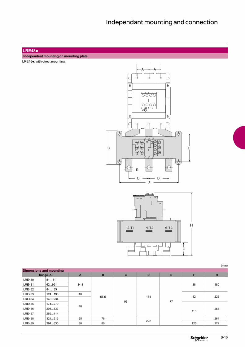
Independant mounting and connection
LRE48p Independent mounting on mounting plate
LRE48p: with direct mounting.
C
R
D B B
E
A
F
H
A
(mm)
Dimensions and mounting Range (A) A B C D E F H
LRE480 51…81
34.8
55.5
93
164
77
38 180LRE481 62...99
LRE482 84...135
LRE483 124...198 40 82 223
LRE484 146...234
48 LRE485 174...279
113 255LRE486 208...333
LRE487 259...414
LRE488 321...513 55 76 222
264
LRE489 394...630 80 80 125 279
B-10
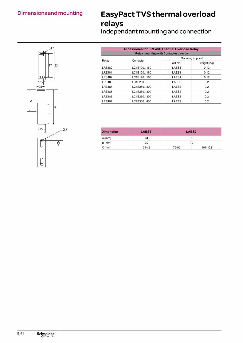
Dimensions and mounting EasyPact TVS thermal overload relaysIndependant mounting and connection
Accessories for LRE48X Thermal Overload Relay Relay mounting with Contactor directly
A
Dimension LAES1 LAES2
77 93
10
25
25
H
B
13
Mounting support Relay Contactor
cat No. weight (Kg)
LRE480 LC1E120...160 LAES1 0.12
LRE481 LC1E120...160 LAES1 0.12
LRE482 LC1E120...160 LAES1 0.12
LRE483 LC1E200 LAES2 0.2
LRE484 LC1E250...300 LAES2 0.2
LRE485 LC1E250...300 LAES2 0.2
LRE486 LC1E250...300 LAES2 0.2
LRE487 LC1E300...400 LAES2 0.2
A (mm) 34 70
B (mm) 30 70
C (mm) 34-42 75-90 107-122
B-11

B-12

EasyPact TVS Motor starters, contactors & relays up to 630 A
EasyPact TVS control relaysC
PB10
0424
CPB
1004
25
CPB
1004
26
Contact configuration
Coil V AC/Hz 50 Hz 50 Hz 50 Hz
24 CAE40B5 CAE22B5 CAE31B5
48 CAE40E5 CAE22E5 CAE31E5
110 CAE40F5 CAE22F5 CAE31F5
220 CAE40M5 CAE22M5 CAE31M5
240 CAE40U5 CAE22U5 CAE31U5
380 CAE40Q5 CAE22Q5 CAE31Q5
415 CAE40N5 CAE22N5 CAE31N5
440 CAE40R5 CAE22R5 CAE31R5
Characteristics > 4 NO/NC contacts. > Weight: 0.280 kg.
C-1
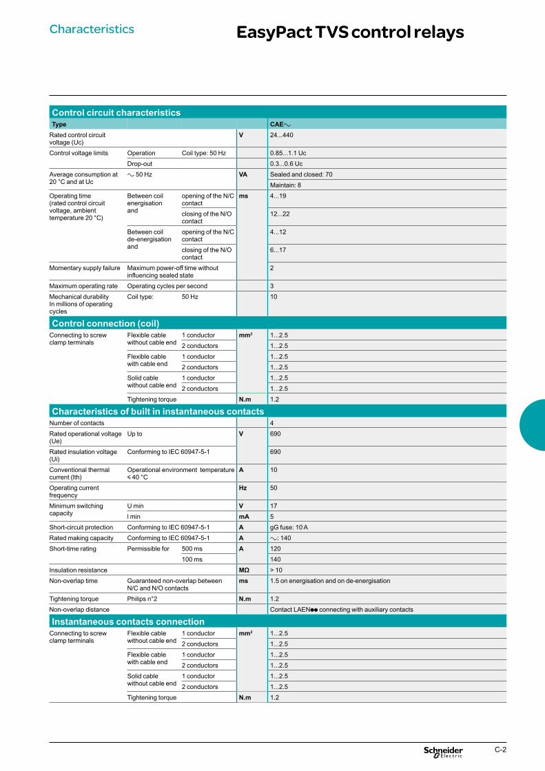
Characteristics EasyPact TVS control relays
Control circuit characteristics Type CAEa
Rated control circuit voltage (Uc)
V 24...440
Control voltage limits Operation Coil type: 50 Hz 0.85...1.1 Uc
Drop-out 0.3...0.6 Uc
Average consumption at 20 °C and at Uc
a 50 Hz VA Sealed and closed: 70
Maintain: 8
Operating time (rated control circuit voltage, ambient temperature 20 °C)
Between coil energisation and
opening of the N/C contact
ms 4...19
closing of the N/O contact
12...22
Between coil de-energisation and
opening of the N/C contact
4...12
closing of the N/O contact
6...17
Momentary supply failure Maximum power-off time without influencing sealed state
2
Maximum operating rate Operating cycles per second 3
Mechanical durability In millions of operating cycles
Coil type: 50 Hz 10
Control connection (coil) mm2 1...2.5
1...2.5
1...2.5
1...2.5
1...2.5
1...2.5
N.m 1.2
Characteristics of built in instantaneous contacts Number of contacts 4
Rated operational voltage (Ue)
Up to V 690
Rated insulation voltage (Ui)
Conforming to IEC 60947-5-1 690
Conventional thermal current (lth)
Operational environment temperature y 40 °C
A 10
Operating current frequency
Hz 50
Minimum switching capacity
U min V 17
l min mA 5
Short-circuit protection Conforming to IEC 60947-5-1 A gG fuse: 10 A
Rated making capacity Conforming to IEC 60947-5-1 A a: 140
Short-time rating Permissible for 500 ms A 120
100 ms 140
Insulation resistance MΩ > 10
Non-overlap time Guaranteed non-overlap between N/C and N/O contacts
ms 1.5 on energisation and on de-energisation
Tightening torque Philips n°2 N.m 1.2
Non-overlap distance Contact LAENpp connecting with auxiliary contacts
Instantaneous contacts connection mm2 1...2.5
1...2.5
1...2.5
1...2.5
1...2.5
1...2.5
N.m 1.2
Connecting to screw Flexible cable 1 conductor clamp terminals without cable end 2 conductors
Flexible cable 1 conductor with cable end 2 conductors
Solid cable 1 conductor without cable end 2 conductors
Tightening torque
Connecting to screw Flexible cable 1 conductor clamp terminals without cable end 2 conductors
Flexible cable 1 conductor with cable end 2 conductors
Solid cable 1 conductor without cable end 2 conductors
Tightening torque
C-2
Characteristics EasyPact TVS control relays
0°
Environment
81
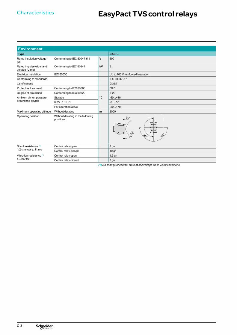
(1) No change of contact state at coil voltage Ue in worst conditions.
Type CAEa
Rated insulation voltage (Ui)
Conforming to IEC 60947-5-1 V 690
Rated impulse withstand voltage (Uimp)
Conforming to IEC 60947 kV 6
Electrical insulation IEC 60536 Up to 400 V reinforced insulation
Conforming to standards IEC 60947-5-1
Certifications GOST
Protective treatment Conforming to IEC 60068 "TH"
Degree of protection Conforming to IEC 60529 IP20
Ambient air temperature around the device
Storage °C -60...+80
0.85...1.1 UC -5...+55
For operation at Uc -20...+70
Maximum operating altitude Without derating m 3000
Operating position Without derating in the following positions
Shock resistance (1)
1/2 sine ware, 11 ms Control relay open 7 gn
Control relay closed 10 gn
Vibration resistance (1)
5...300 Hz Control relay open 1.5 gn
Control relay closed 3 gn 90°90°
C-3

Mounting dimension EasyPact TVS control relaysControl relays and auxiliary blocks
CAEpp
CAE 32 50
c1
90
LAERCp
c 80 80
c1 with LAEN 113 113
CAE On mounting plate AM1-P
2 x Ø4.8
CAEa
50
C G
2 x Ø4.5
c 80
G 35
CAE40 CAE31 CAE22
A2
A1 13/N
O14
23/N
O24
33/N
O34
43/N
O44
14
13/N
O
22
21/N
C
3433
/NO
43/N
O44 14
13
/NO
22
21/N
C
31/N
C
4432
43/N
O
C-4
Accessories EasyPact TVS control relaysAuxiliary contact blocks RC suppressor
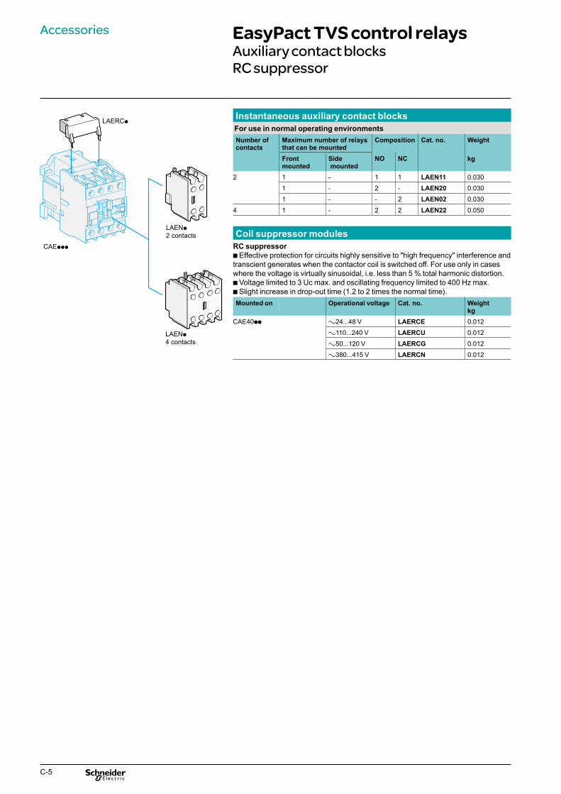
LAERCp Instantaneous auxiliary contact blocks For use in normal operating environments Number of contacts
Maximum number of relays that can be mounted
Composition Cat. no. Weight
Front mounted
Side mounted
NO NC kg
2 1 - 1 1 LAEN11 0.030
1 - 2 - LAEN20 0.030
1 - - 2 LAEN02 0.030
4 1 - 2 2 LAEN22 0.050
LAENp 2 contacts
CAEppp
Coil suppressor modules RC suppressor b Effective protection for circuits highly sensitive to "high frequency" interference and transcient generates when the contactor coil is switched off. For use only in cases where the voltage is virtually sinusoidal, i.e. less than 5 % total harmonic distortion. b Voltage limited to 3 Uc max. and oscillating frequency limited to 400 Hz max. b Slight increase in drop-out time (1.2 to 2 times the normal time).
LAENp 4 contacts
Mounted on Operational voltage Cat. no. Weight kg
CAE40pp a24...48 V LAERCE 0.012
a110...240 V LAERCU 0.012
a50...120 V LAERCG 0.012
a380...415 V LAERCN 0.012
C-5
C-6

Presentation, Protection componentscharacteristics Thermal-magnetic motor circuit-breakers
GZ1 E
Presentation GZ1 E motor circuit-breakers are 3-pole thermal-magnetic circuit-breakers specifically designed for the control and protection of motors, conforming to standards IEC 60947-2 and IEC 60947-4-1.
1 Connection These circuit-breakers are designed for connection by screw clamp terminals. This technique ensures secure, permanent and durable clamping that is resistant to harsh environments, vibration and impact and is even
2
3 more effective when conductors without cable ends are used. Each connection can take two independent conductors.
Pushbutton control.Energisation is controlled manually by operating the Start button “I” 1. De-energisation is controlled manually by operating the Stop button “O” 2, orautomatically by the thermal-magnetic protection elements or by a voltagetrip attachment.
Protection of motors and personnel Motor protection is provided by the thermal-magnetic protection elements incorporated in the motor circuit-breaker. The magnetic elements (short-circuit protection) have a non-adjustable tripping threshold, which is equal to about 13 times the maximum setting current of the thermal trips. The thermal elements (overload protection) include automatic compensation for ambient temperature variations. The rated operational current of the motor is displayed by means of a graduated knob 3. Personnel protection is also provided. All live parts are protected against direct finger contact. GZ1 E motor circuit-breakers are easily installed in any confi guration thanks to their universal fi xing arrangement: screw fi xing or clip-on mounting on symmetrical, asymmetrical or combination rails.
Environment Circuit-breaker type GZ1 E
Conforming to standards IEC 60947-2, IEC 60947-4
Protective treatment “TH”
Degree of protection In GV2 MC01 enclosure: IP 41 In GV2 MC02 enclosure: IP 55
Ambient air temperature Storage °C - 40…+ 80
Operation - 20…+ 60
Flame resistance Conforming to IEC 60695-2-1 °C 960
Maximum operating altitude m 2000
Cabling Number of conductors and c.s.a.
Min. Max. Solid cable mm2 2 x 1 2 x 6
Flexible cable without cable end mm2 2 x 1.5 2 x 6
Flexible cable with cable end mm2 2 x 1 2 x 4
Suitable for isolation Conforming to IEC 60947-1 § 7-1-6
Yes
Tightening torque N.m 1,7
Rated operational voltage (Ue)
Conforming to IEC 60947-2 V 690
Rated insulation voltage (Ui)
Conforming to IEC 60947-2 V 690
Rated operational frequencyConforming to IEC 60947-2 Hz 50/60
Rated impulse withstand voltage (U imp)
Conforming to IEC 60947-2 kV 6
Total power dissipated per pole
W 2.5
Mechanical durability (C.O.: closing, opening)
C.O. 100 000
Electrical durability For AC-3 duty CF.O. 100 000
Duty class (maximum operating rate)
C.O./h 25
D-1

Characteristics (continued) Protection componentsThermal-magnetic motor circuit-breakers GZ1 E
Breaking capacity Circuit-breaker type GZ1 E
01 to 06 07 08 10 14 16 20 21 22 to 32 Rating A 0.1 to 1.6 2,5 4 6.3 10 14 18 23 25 to 32 Breaking capacity 230/240 V Icu kA g g g g g g g 30 30
conforming to IEC 60947-2 Ics % (1) g g g g g g g 100 100
400/415 V Icu kA g g g g g 10 10 10 10
Ics % (1) g g g g g 50 50 40 40
440 V Icu kA g g g 30 10 6 6 5 5
Ics % (1) g g g 100 100 50 50 50 50
500 V Icu kA g g g 30 8 5 5 3 3
Ics % (1) g g g 100 100 75 75 75 75
690 V Icu kA g 2 2 2 2 2 2 2 2
Ics % (1) g 75 75 75 75 75 75 75 75
g > 100 kA. (1) As % of Icu.
Tripping curves Average operating times at 20 °C related to multiples of the setting current
Time (s)
1 3 poles from cold state 2 2 poles from cold state
1 1,5 10 100 3 3 poles from hot state x the setting current (Ir)
0,001
0,1
1
10
100
0,01
1000
10 000
1 2 3
D-2

References Protection componentsThermal-magnetic motor circuit-breakers GZ1 E
CP
B10
0407
Motor circuit-breakers Pushbutton control Standard power ratings of 3-phase motors 50/60 Hz in category AC-3
Setting range of thermal trips
Magnetic tripping current Id ± 20 %
Reference Weight
230 V 400 V 440 V 500 V 690 V kW kW kW kW kW A A kg – – – – – 0.1…0.16 1.5 GZ1 E01 0.260
– – – – – 0.16…0.25 2.4 GZ1 E02 0.260
– – – – – 0.25…0.40 5 GZ1 E03 0.260 GZ1 E – – – – 0.37 0.40…0.63 8 GZ1 E04 0.260
– – – 0.37 0.55 0.63…10 13 GZ1 E05 0.260
– 0.37 0.55 0.75 1.1 1…1.6 22.5 GZ1 E06 0.260
0.37 0.75 1.1 1.1 1.5 1.6…2.5 33.5 GZ1 E07 0.260
0.75 1.5 1.5 2.2 3 2.5…4 51 GZ1 E08 0.260
1.1 2.2 3 3.7 4 4…6.3 78 GZ1 E10 0.260
2.2 4 4 5.5 7.5 6…10 138 GZ1 E14 0.260
– 5.5 5.5 9 11 9…14 170 GZ1 E16 0.260
4 7.5 9 10 15 13…18 223 GZ1 E20 0.260
5.5 9 11 11 18.5 17…23 327 GZ1 E21 0.260
5.,5 11 11 15 22 20…25 327 GZ1 E22 0.260
7.5 15 15 18.5 22 24…32 416 GZ1 E32 0.260
D-3

References Protection componentsThermal-magnetic motor circuit-breakers GZ1 E
Contact blocks Instantaneous auxiliary contacts Mounting Maximum
number Type of contacts
Side 2 N/O + N/C
LH side N/O + N/O
Sold in lots of 1
1
Unit reference GZ1 AN11 GZ1 AN20
Weight kg 0.050
0.050
Montage Type Tension Reference Weightkg
Electric trips
GZ1 AN11 Side Undervoltage 110…115 V 50 Hz GZ1 AU115 0.105 (1 block on trip 220…240 V 50 Hz GZ1 AU225 0.105RH side of circuit- 380…400 V 50 Hz GZ1 AU385 0.105 breaker) Shunt trip 110…115 V 50 Hz GZ1 AS115 0.105
220…240 V 50 Hz GZ1 AS225 0.105
Mounting accessory Description Application Sold in Unit Weight
lots of reference kg Adapter plate For screw 10 GV2 AF02 0.021
fixing of a GZ1 E
GZ1 AS115
D-4
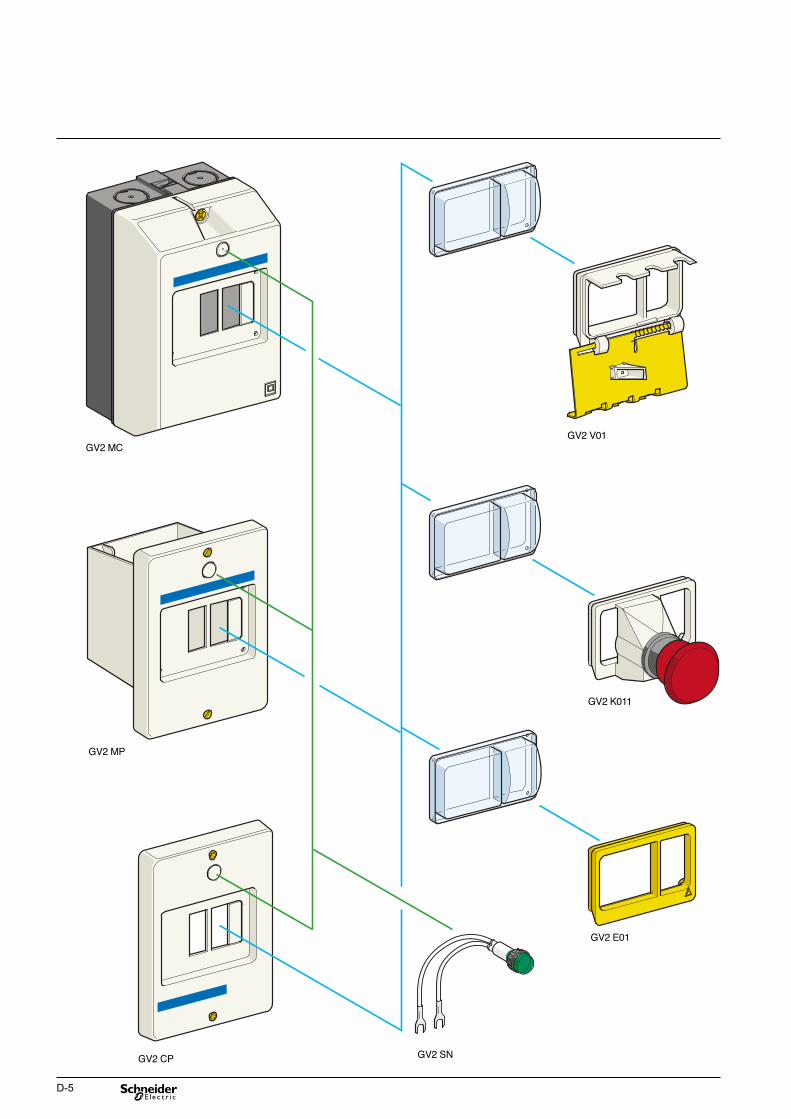
GV2 MC
GV2 E01
GV2 K011
GV2 V01
GV2 MP
GV2 SNGV2 CP GV2 SN
D-5

References Protection componentsThermal-magnetic motor circuit-breakers GZ1 E
Enclosures for thermal-magnetic circuit-breakers GZ1 E Type Degree of protection Reference Weight
kg Surface mounting, double insulated, IP 41 GV2 MC01 0.290 with protective earth Sealable cover IP 55 GV2 MC02 0.300
Flush mounting, IP 41 (front face) GV2 MP01 0.115 with protective earth IP 55 (front face) GV2 MP02 0.130
Front plate Description Degree of protection Sold in
lots of Unit reference
Weight kg
For direct control, IP 55 1 GV2 CP21 0.800 through a panel, of a chassis mounted GZ1 E
Padlocking device (1)
for GZ1 E operator 1 to 3 padlocks Ø 4 to 8 mm
1 GV2 V01 0.075
(padlocking is only possible in the “O” position)
Mushroom head Spring return (1) 1 GV2 K011 0.052 “Stop” pushbutton, Ø 40 mm, red Sealing kit For enclosures and front plate IP 55 10 GV2 E01 0.012
Neutral terminal 100 AB1 VV635UBL 0.015
Accessories common to all enclosures (to be ordered separately)
Partition 50 AB1 AC6BL 0.003
Description
Pilot lightwith neon bulb
VoltageV 380/440
Colour
Green
Red
Orange
Clear
Sold in lots of 10
10
10
10
Unit reference GV2 SN33 GV2 SN34 GV2 SN35 GV2 SN37
Weightkg 0.019
0.019
0.019
0.019 (1) Supplied with IP 55 sealing kit. To be fitted with enclosures GV2 Mp01.
D-6
Dimensions, Protection componentsmounting Thermal-magnetic motor circuit-breakers
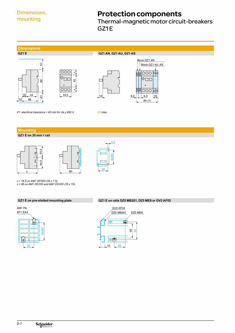
GZ1 E
Dimensions GZ1 E
16
89
44
12 66
X1X1
GZ1 AN, GZ1 AU, GZ1 AS
Block GZ1 AN
==
45
44,5 12 9,3 9,3 18 84 (1)
Block GZ1 AU, AS
X1: electrical clearance = 40 mm for Ue y 690 V. (1) max.
Mounting GZ1 E on 35 mm y rail
44,5
44,5
c 80
50/6
0
35
4,2
c = 78.5 on AM1 DP200 (35 x 7.5).c = 86 on AM1 DE200 and AM1 ED200 (35 x 15).
GZ1 E on pre-slotted mounting plate GZ1 E on rails DZ5 MB201, DZ5 ME8 or GV2 AF02
AM1 PA GV2 AF02 AF1 EA4
50/6
0
35 3515
6050
DZ5 MB201 DZ5 ME8
D-7
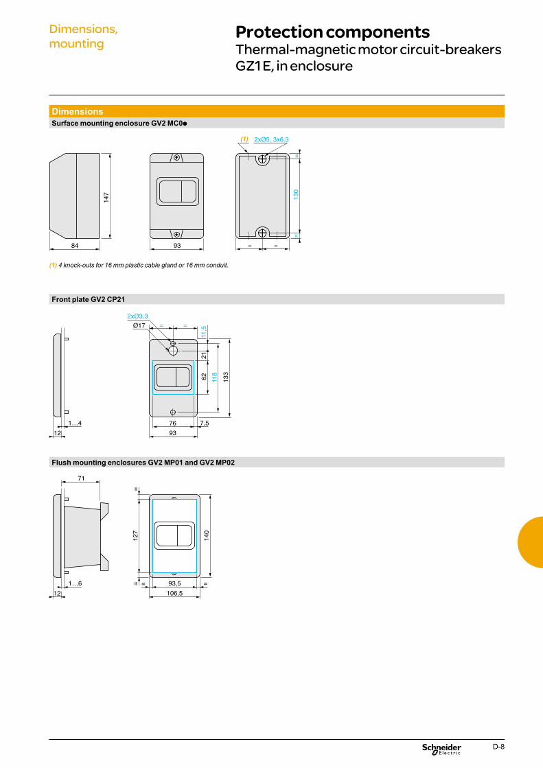
Dimensions, Protection componentsmounting Thermal-magnetic motor circuit-breakers
GZ1 E, in enclosure
Dimensions Surface mounting enclosure GV2 MC0p
2xØ5, 3x6,3
84
130
147
93 = =
(1)
==
(1) 4 knock-outs for 16 mm plastic cable gland or 16 mm conduit.
Front plate GV2 CP21
2xØ3,3
12
1…4 76 7,5
93
Ø17
62
21
133
11,5
= =
118
Flush mounting enclosures GV2 MP01 and GV2 MP02
71
12
127
=1…6 93,5
106,5
= =
140
=
D-8

EasyPact TVS Motor starters, contactors & relays up to 630 A
Coordination between protection& control components
Coordination: safety and faster restart after a short circuit This benefit is obtained by choosing contactors with Schneider Electric guaranteed coordination.
What exactly is coordination? A contactor is said to be "coordinated" with the upstream protection device when its behaviour is controlled in the event of a short circuit. This behaviour can be: > type 1: guaranteed not to pose a danger to the workforce and not to
damage the installation. It is accepted that the contactor should be destroyed or repaired.
> type 2: type 1 + put back into service possible after any maintenance operation (contact separation, for example).
Compliance tests Only the very stringent certified tests performed by Schneider Electric can guarantee the behaviour described by IEC 60947-4-1.
E-1
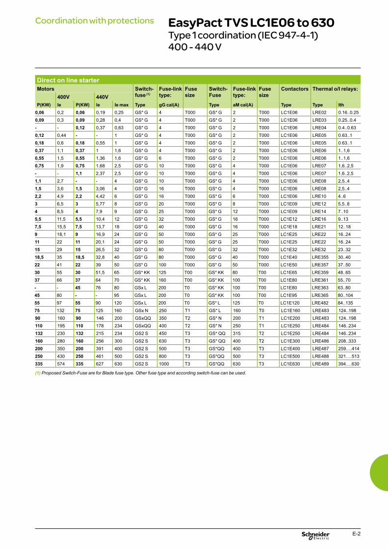
Coordination with protections EasyPact TVS LC1E06 to 630Type 1 coordination (IEC 947-4-1) 400 - 440 V
Direct on line starter Motors Switch-
fuse (1) Fuse-link type:
Fuse size
Switch-Fuse
Fuse-link type:
Fuse size
Contactors Thermal o/l relays: 400V 440V
P(KW) Ie P(KW) Ie Ie max Type gG cal(A) Type aM cal(A) Type Type Ith 0,06 0,2 0,06 0,19 0,25 GS* G 4 T000 GS* G 2 T000 LC1E06 LRE02 0.16..0.25
0,09 0,3 0,09 0,28 0,4 GS* G 4 T000 GS* G 2 T000 LC1E06 LRE03 0.25..0.4
- - 0,12 0,37 0,63 GS* G 4 T000 GS* G 2 T000 LC1E06 LRE04 0.4..0.63
0,12 0,44 - - 1 GS* G 4 T000 GS* G 2 T000 LC1E06 LRE05 0.63..1
0,18 0,6 0,18 0,55 1 GS* G 4 T000 GS* G 2 T000 LC1E06 LRE05 0.63..1
0,37 1,1 0,37 1 1,6 GS* G 4 T000 GS* G 2 T000 LC1E06 LRE06 1..1,6
0,55 1,5 0,55 1,36 1,6 GS* G 6 T000 GS* G 2 T000 LC1E06 LRE06 1..1,6
0,75 1,9 0,75 1,68 2,5 GS* G 10 T000 GS* G 4 T000 LC1E06 LRE07 1,6..2,5
- - 1,1 2,37 2,5 GS* G 10 T000 GS* G 4 T000 LC1E06 LRE07 1,6..2,5
1,1 2,7 - - 4 GS* G 10 T000 GS* G 4 T000 LC1E06 LRE08 2,5..4
1,5 3,6 1,5 3,06 4 GS* G 16 T000 GS* G 4 T000 LC1E06 LRE08 2,5..4
2,2 4,9 2,2 4,42 6 GS* G 16 T000 GS* G 6 T000 LC1E06 LRE10 4..6
3 6,5 3 5,77 8 GS* G 20 T000 GS* G 8 T000 LC1E09 LRE12 5,5..8
4 8,5 4 7,9 9 GS* G 25 T000 GS* G 12 T000 LC1E09 LRE14 7..10
5,5 11,5 5,5 10,4 12 GS* G 32 T000 GS* G 16 T000 LC1E12 LRE16 9..13
7,5 15,5 7,5 13,7 18 GS* G 40 T000 GS* G 16 T000 LC1E18 LRE21 12..18
9 18,1 9 16,9 24 GS* G 50 T000 GS* G 25 T000 LC1E25 LRE22 16..24
11 22 11 20,1 24 GS* G 50 T000 GS* G 25 T000 LC1E25 LRE22 16..24
15 29 15 26,5 32 GS* G 80 T000 GS* G 32 T000 LC1E32 LRE32 23..32
18,5 35 18,5 32,8 40 GS* G 80 T000 GS* G 40 T000 LC1E40 LRE355 30..40
22 41 22 39 50 GS* G 100 T000 GS* G 50 T000 LC1E50 LRE357 37..50
30 55 30 51,5 65 GS* KK 125 T00 GS* KK 80 T00 LC1E65 LRE359 48..65
37 66 37 64 70 GS* KK 160 T00 GS* KK 100 T00 LC1E80 LRE361 55..70
- - 45 76 80 GSx L 200 T0 GS* KK 100 T00 LC1E80 LRE363 63..80
45 80 - - 95 GSx L 200 T0 GS* KK 100 T00 LC1E95 LRE365 80..104
55 97 55 90 120 GSx L 200 T0 GS* L 125 T0 LC1E120 LRE482 84..135
75 132 75 125 160 GSx N 250 T1 GS* L 160 T0 LC1E160 LRE483 124..198
90 160 90 146 200 GSxQQ 350 T2 GS* N 200 T1 LC1E200 LRE483 124..198
110 195 110 178 234 GSxQQ 400 T2 GS* N 250 T1 LC1E250 LRE484 146..234
132 230 132 215 234 GS2 S 450 T3 GS* QQ 315 T2 LC1E250 LRE484 146..234
160 280 160 256 300 GS2 S 630 T3 GS* QQ 400 T2 LC1E300 LRE486 208..333
200 350 200 391 400 GS2 S 500 T3 GS*QQ 400 T3 LC1E400 LRE487 259….414
250 430 250 461 500 GS2 S 800 T3 GS*QQ 500 T3 LC1E500 LRE488 321….513
335 574 335 627 630 GS2 S 1000 T3 GS*QQ 630 T3 LC1E630 LRE489 394….630
(1) Proposed Switch-Fuse are for Blade fuse type. Other fuse type and according switch-fuse can be used.
E-2
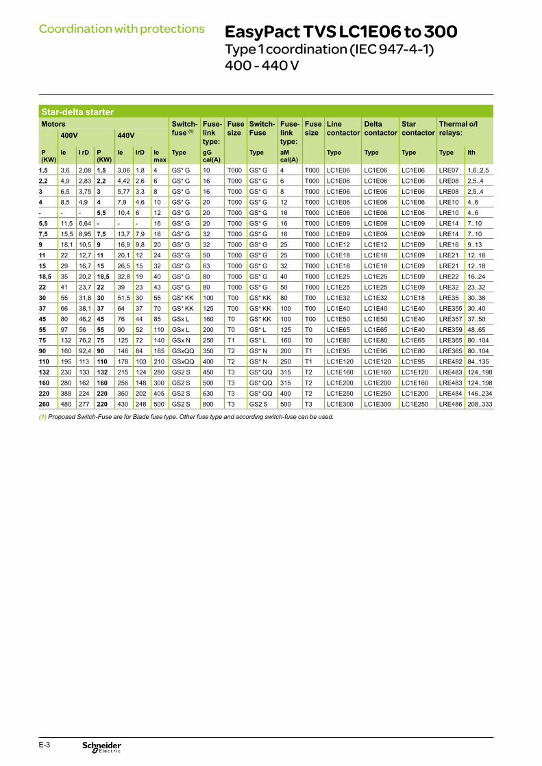
Coordination with protections EasyPact TVS LC1E06 to 300Type 1 coordination (IEC 947-4-1) 400 - 440 V
Star-delta starter Motors Switch-
fuse (1) Fuse-link type:
Fuse size
Switch-Fuse
Fuse-link type:
Fuse size
Line contactor
Delta contactor
Star contactor
Thermal o/l relays:400V 440V
P (KW)
Ie I rD P (KW)
Ie IrD Ie max
Type gG cal(A)
Type aM cal(A)
Type Type Type Type Ith
1,5 3,6 2,08 1,5 3,06 1,8 4 GS* G 10 T000 GS* G 4 T000 LC1E06 LC1E06 LC1E06 LRE07 1,6..2,5
2,2 4,9 2,83 2,2 4,42 2,6 6 GS* G 16 T000 GS* G 6 T000 LC1E06 LC1E06 LC1E06 LRE08 2,5..4
3 6,5 3,75 3 5,77 3,3 8 GS* G 16 T000 GS* G 8 T000 LC1E06 LC1E06 LC1E06 LRE08 2,5..4
4 8,5 4,9 4 7,9 4,6 10 GS* G 20 T000 GS* G 12 T000 LC1E06 LC1E06 LC1E06 LRE10 4..6
- - - 5,5 10,4 6 12 GS* G 20 T000 GS* G 16 T000 LC1E06 LC1E06 LC1E06 LRE10 4..6
5,5 11,5 6,64 - - - 16 GS* G 20 T000 GS* G 16 T000 LC1E09 LC1E09 LC1E09 LRE14 7..10
7,5 15,5 8,95 7,5 13,7 7,9 16 GS* G 32 T000 GS* G 16 T000 LC1E09 LC1E09 LC1E09 LRE14 7..10
9 18,1 10,5 9 16,9 9,8 20 GS* G 32 T000 GS* G 25 T000 LC1E12 LC1E12 LC1E09 LRE16 9..13
11 22 12,7 11 20,1 12 24 GS* G 50 T000 GS* G 25 T000 LC1E18 LC1E18 LC1E09 LRE21 12..18
15 29 16,7 15 26,5 15 32 GS* G 63 T000 GS* G 32 T000 LC1E18 LC1E18 LC1E09 LRE21 12..18
18,5 35 20,2 18,5 32,8 19 40 GS* G 80 T000 GS* G 40 T000 LC1E25 LC1E25 LC1E09 LRE22 16..24
22 41 23,7 22 39 23 43 GS* G 80 T000 GS* G 50 T000 LC1E25 LC1E25 LC1E09 LRE32 23..32
30 55 31,8 30 51,5 30 55 GS* KK 100 T00 GS* KK 80 T00 LC1E32 LC1E32 LC1E18 LRE35 30..38
37 66 38,1 37 64 37 70 GS* KK 125 T00 GS* KK 100 T00 LC1E40 LC1E40 LC1E40 LRE355 30..40
45 80 46,2 45 76 44 85 GSx L 160 T0 GS* KK 100 T00 LC1E50 LC1E50 LC1E40 LRE357 37..50
55 97 56 55 90 52 110 GSx L 200 T0 GS* L 125 T0 LC1E65 LC1E65 LC1E40 LRE359 48..65
75 132 76,2 75 125 72 140 GSx N 250 T1 GS* L 160 T0 LC1E80 LC1E80 LC1E65 LRE365 80..104
90 160 92,4 90 146 84 165 GSxQQ 350 T2 GS* N 200 T1 LC1E95 LC1E95 LC1E80 LRE365 80..104
110 195 113 110 178 103 210 GSxQQ 400 T2 GS* N 250 T1 LC1E120 LC1E120 LC1E95 LRE482 84..135
132 230 133 132 215 124 280 GS2 S 450 T3 GS* QQ 315 T2 LC1E160 LC1E160 LC1E120 LRE483 124..198
160 280 162 160 256 148 300 GS2 S 500 T3 GS* QQ 315 T2 LC1E200 LC1E200 LC1E160 LRE483 124..198
220 388 224 220 350 202 405 GS2 S 630 T3 GS* QQ 400 T2 LC1E250 LC1E250 LC1E200 LRE484 146..234
260 480 277 220 430 248 500 GS2 S 800 T3 GS2 S 500 T3 LC1E300 LC1E300 LC1E250 LRE486 208..333
(1) Proposed Switch-Fuse are for Blade fuse type. Other fuse type and according switch-fuse can be used.
E-3
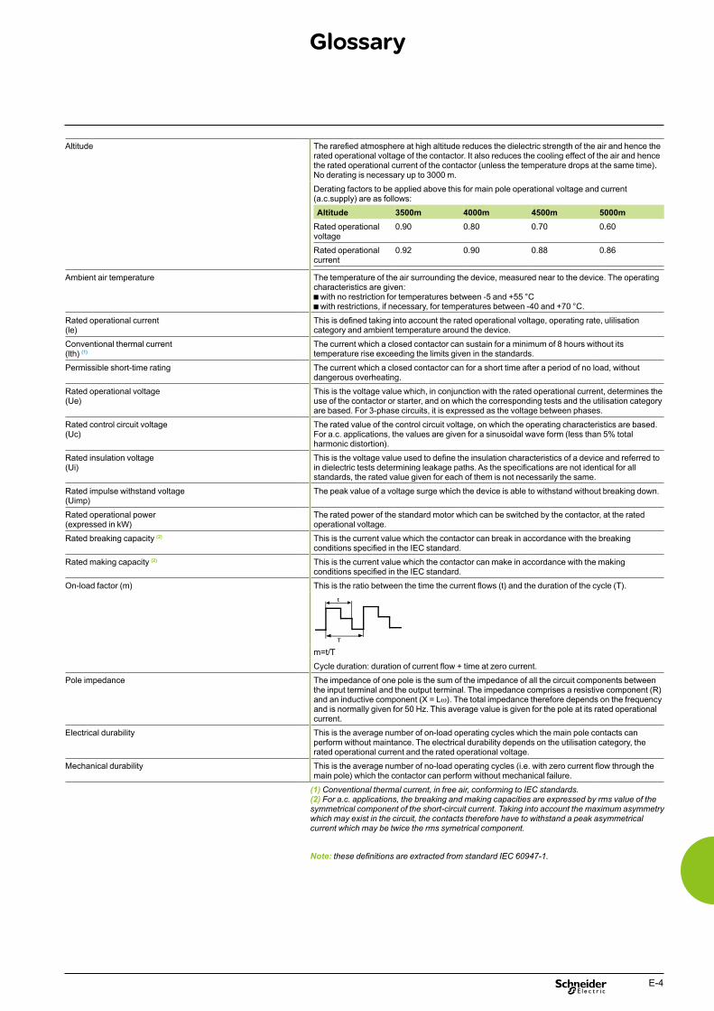
Glossary
Altitude
Ambient air temperature
Rated operational current (le)
Conventional thermal current (lth) (1)
Permissible short-time rating
Rated operational voltage (Ue)
Rated control circuit voltage (Uc)
Rated insulation voltage (Ui)
Rated impulse withstand voltage (Uimp)
Rated operational power (expressed in kW)
Rated breaking capacity (2)
Rated making capacity (2)
On-load factor (m)
Pole impedance
Electrical durability
Mechanical durability
The rarefied atmosphere at high altitude reduces the dielectric strength of the air and hence the rated operational voltage of the contactor. It also reduces the cooling effect of the air and hence the rated operational current of the contactor (unless the temperature drops at the same time). No derating is necessary up to 3000 m.
Derating factors to be applied above this for main pole operational voltage and current (a.c.supply) are as follows:
Altitude 3500m 4000m 4500m 5000m Rated operational 0.90 0.80 0.70 0.60 voltage
Rated operational 0.92 0.90 0.88 0.86 current
The temperature of the air surrounding the device, measured near to the device. The operating characteristics are given: b with no restriction for temperatures between -5 and +55 °C b with restrictions, if necessary, for temperatures between -40 and +70 °C.
This is defined taking into account the rated operational voltage, operating rate, ulilisation category and ambient temperature around the device.
The current which a closed contactor can sustain for a minimum of 8 hours without its temperature rise exceeding the limits given in the standards.
The current which a closed contactor can for a short time after a period of no load, without dangerous overheating.
This is the voltage value which, in conjunction with the rated operational current, determines the use of the contactor or starter, and on which the corresponding tests and the utilisation category are based. For 3-phase circuits, it is expressed as the voltage between phases.
The rated value of the control circuit voltage, on which the operating characteristics are based. For a.c. applications, the values are given for a sinusoidal wave form (less than 5% total harmonic distortion).
This is the voltage value used to define the insulation characteristics of a device and referred to in dielectric tests determining leakage paths. As the specifications are not identical for all standards, the rated value given for each of them is not necessarily the same.
The peak value of a voltage surge which the device is able to withstand without breaking down.
The rated power of the standard motor which can be switched by the contactor, at the rated operational voltage.
This is the current value which the contactor can break in accordance with the breaking conditions specified in the IEC standard.
This is the current value which the contactor can make in accordance with the making conditions specified in the IEC standard.
This is the ratio between the time the current flows (t) and the duration of the cycle (T).
m=t/T
Cycle duration: duration of current flow + time at zero current.
The impedance of one pole is the sum of the impedance of all the circuit components between the input terminal and the output terminal. The impedance comprises a resistive component (R) and an inductive component (X = Lω). The total impedance therefore depends on the frequency and is normally given for 50 Hz. This average value is given for the pole at its rated operational current.
This is the average number of on-load operating cycles which the main pole contacts can perform without maintance. The electrical durability depends on the utilisation category, the rated operational current and the rated operational voltage.
This is the average number of no-load operating cycles (i.e. with zero current flow through the main pole) which the contactor can perform without mechanical failure.
(1) Conventional thermal current, in free air, conforming to IEC standards. (2) For a.c. applications, the breaking and making capacities are expressed by rms value of the symmetrical component of the short-circuit current. Taking into account the maximum asymmetry which may exist in the circuit, the contacts therefore have to withstand a peak asymmetrical current which may be twice the rms symetrical component.
Note: these definitions are extracted from standard IEC 60947-1.
E-4

Application Definitions
Contactor utilisation categories conforming to IEC 60947-4 The standard utilisation categories define the current values which the contactor must be able to make or break.These values depend on:b the type of load being switched: squirrel cage or slip ring motor, resistorsb the conditions under which making or breaking takes place: motor stalled, starting or running, reversing, plugging.
a.c. applicationsb Category AC-1:This category applies to all types of a.c. load with a power factor equal to or greater than 0.95.Examples: heating, lighting, distribution.b Category AC-3:This category applies to squirrel cage motors with breaking during normal running of the motor. On closing, the contactor makes the starting current, which is about 7 times the rated current of the motor.On opening, it breaks the rated current drawn by the motor; at this point, the voltage at the contactor terminals is about 20 % of the mains supply voltage. Breaking is light. For example: all standard squirrel cage motors: lifts, escalators, conveyor belts, bucket elevators, compressors, pumps, mixers, air condition units, etc...b Category AC-4:The contactor closes at a current peak which may be as high as 5 or 7 times the rated motor current. On opening it breaks this same current at a voltage which is higher, the lower the motor speed. This voltage can be the same as the mains voltage. Breaking is severe.This category covers applications with plugging and inching of squirrel cage and slip ring motors.For example: printing machines, wire drawing machines, cranes and hoists, metallurgy industry.
E-5
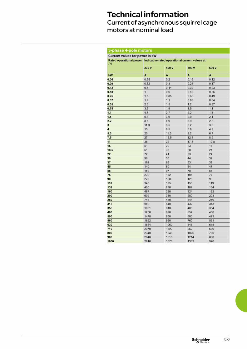
Technical information Current of asynchronous squirrel cage motors at nominal load
3-phase 4-pole motors Current values for power in kW Rated operational power (1)
Indicative rated operational current values at:
230 V 400 V 500 V 690 V
kW A A A A 0.06 0.35 0.2 0.16 0.12
0.09 0.52 0.3 0.24 0.17
0.12 0.7 0.44 0.32 0.23
0.18 1 0.6 0.48 0.35
0.25 1.5 0.85 0.68 0.49
0.37 1.9 1.1 0.88 0.64
0.55 2.6 1.5 1.2 0.87
0.75 3.3 1.9 1.5 1.1
1.1 4.7 2.7 2.2 1.6
1.5 6.3 3.6 2.9 2.1
2.2 8.5 4.9 3.9 2.8
3 11.3 6.5 5.2 3.8
4 15 8.5 6.8 4.9
5.5 20 11.5 9.2 6.7
7.5 27 15.5 12.4 8.9
11 38 22 17.6 12.8
15 51 29 23 17
18.5 61 35 28 21
22 72 41 33 24
30 96 55 44 32
37 115 66 53 39
45 140 80 64 47
55 169 97 78 57
75 230 132 106 77
90 278 160 128 93
110 340 195 156 113
132 400 230 184 134
160 487 280 224 162
200 609 350 280 203
250 748 430 344 250
315 940 540 432 313
355 1061 610 488 354
400 1200 690 552 400
500 1478 850 680 493
560 1652 950 760 551
630 1844 1060 848 615
710 2070 1190 952 690
800 2340 1346 1076 780
900 2640 1518 1214 880
1000 2910 1673 1339 970
E-6

Application Technical information Product standards and certifications
Standardisation Conformity to standards
Schneider Electric products satisfy, in the majority of cases, European (for example: CENELEC) or international (IEC) standards. These product standards precisely define the performance of the designated products (such as IEC 60947 for low voltage equipment).When used correctly, as designated by the manufacturer and in accordance with regulations and correct practices, these products will allow users to build equipment, machine systems or installations that conform to their appropriate standards (for example: IEC 60204-1, relating to electrical equipment used on industrial machines).Schneider Electric is able to provide proof of conformity of its production to the standards it has chosen to comply with, through its quality assurance system.On request, and depending on the situation, Schneider Electric can provide the following:b a declaration of conformityb a certificate of conformity (ASEFA/LOVAG)b a homologation certificate or approval, in the countries where this procedure is required or for particular specifications, such as those existing in the merchant navy.
Code Certification authority Country Name Abbreviation
GOST Gosudarstvenne Komitet Standartov GOST Russia
IEC International Electrotechnical Commission IEC Worldwide
Regulations European Directives
Opening up of European markets assumes harmonisation of the regulations pertaining to each of the member countries of the European Union. The purpose of the European Directive is to eliminate obstacles hindering the free circulation of goods within the European Union, and it must be applied in all member countries. Member countries are obliged to transcribe each Directive into their national legislation and to simultaneously withdraw any contradictory regulations. The Directives, in particular those of a technical nature which concern us, only establish the objectives to be achieved, referred to as “essential requirements”. The manufacturer must take all the necessary measures to ensure that his products conform to the requirements of each Directive applicable to his production. As a general rule, the manufacturer certifies conformity to the essential requirements of the Directive(s) for his product by affixing the e mark.The e mark is affixed to Schneider Electric brand products concerned, in order to comply with French and European regulations.
Significance of the e mark b The e mark affixed to a product signifies that the manufacturer certifies that the product conforms to the relevant European Directive(s) which concern it; this condition must be met to allow free distribution and circulation within the countries of the European Union of any product subject to one or more of the E.U. Directives. b The e mark is intended solely for national market control authorities. b The e mark must not be confused with a conformity marking.
European Directives (continued) For electrical equipment, only conformity to standards signifies that the product is suitable for its designated function, and only the guarantee of an established manufacturer can provide a high level of quality assurance. For Schneider Electric brand products, one or several Directives are likely to be applicable, depending on the product, and in particular: b the Low Voltage Directive 2006/95/EC: the e mark relating to this Directive has been compulsory since 16th January 2007. b the Electromagnetic Compatibility Directive 89/336/EEC, amended by Directives 92/31/EEC and 93/68/EEC: the e mark on products covered by this Directive has been compulsory since 1st January 1996.
ASEFA-LOVAG certification The function of ASEFA (Association des Stations d’Essais Française d’Appareils électriques - Association of French Testing Stations for Low Voltage Industrial Electrical Equipment) is to carry out tests of conformity to standards and to issue certificates of conformity and test reports. ASEFA laboratories are authorised by the French authorisation committee (COFRAC).ASEFA is now a member of the European agreement group LOVAG (Low Voltage Agreement Group). This means that any certificates issued by LOVAG/ASEFA are recognised by all the authorities which are members of the group and carry the same validity as those issued by any of the member authorities.
Note For further details on a specific product, please refer to the "Characteristics" pages in this catalogue or consult your Regional Sales Office.
E-7

E-8

AR
T96
0595
© 2
012
- S
chne
ider
Ele
ctric
- A
ll rig
hts
rese
rved
Schneider Electric Industries SAS 35, rue Joseph Monier As standards, specifications and designs change from time to time, please ask for confirmation CS 30323 of the information given in this publication. F - 92506 Rueil Malmaison Cedex
This document has been printed on ecological paper. RCS Nanterre 954 503 439 Capital social 896 313 776 € Design: Schneider Electric www.schneider-electric.com Photos: Schneider Electric
Printed:
LVED212071EN 10-2012