motor operating device nal/nalf uemc 40 k3 ... - abb · pdf filenectors axle, extension axle...
TRANSCRIPT
1
������������� ����
��������������� ������������ ������������
Motor Operating Device NAL/NALF UEMC 40 K3_
2
�������������� ����
��������
1. General .......................................................... 3
2. Standards ....................................................... 3
3. Transport and storage ................................... 3
4. Construction ................................................... 3
5. Alternative methods of mounting .................. 4
6. Installation ...................................................... 6
7. Electrical connection ...................................... 8
8. Operation ....................................................... 9
9. Accessories .................................................... 10
10. Service ........................................................... 13
11. Spare parts and repairs ................................ 13
12. Range of models ........................................... 14
13. Technical details ............................................ 15
14. Instruction for recycling the product ............. 16
15. Dimension drawings ...................................... 19
16. Circuit diagrams ............................................. 20
3
1. GeneralThis motor operating device is mainly intended foroperating NAL and NALF disconnectors. The motoroperating device can be mounted directly on the frameof the disconnector, or on the side of the cubicle. Thesame motor operating device can be used to operatedisconnectors with both K- and A-mechanisms.
The motor operating device will disengage from thedisconnector after each operation so that it is possibleto operate the disconnector directly from the discon-nectors axle, extension axle or with a separate manualoperating device.For disconnectors with KS-mechanism refer to motoroperating device UEMC 40 A_ and UEMC 40 D_,installation- and operating guide 34 UEMC 36 GB.
2. StandardsThe motor operating device compies with the followingstandards:– IEC 265
– voltage test 2 kV, 50 Hz, 1 min, except for the motor1.5 kV
3. Transport and storageThe motor operating device is delivered complete ina cardboard box. The type number is marked on thebox. If the device is to be stored for a long period, itshould be stored indoors in a dry place.
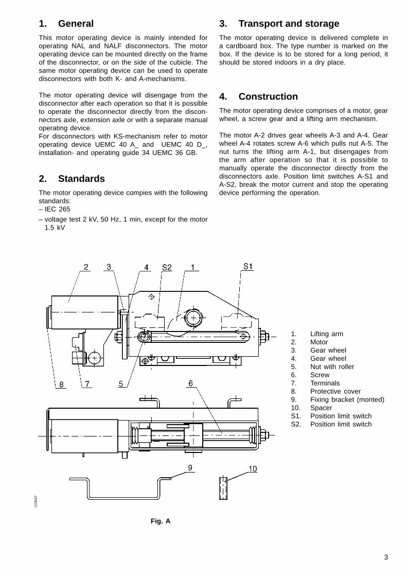
4. ConstructionThe motor operating device comprises of a motor, gearwheel, a screw gear and a lifting arm mechanism.
The motor A-2 drives gear wheels A-3 and A-4. Gearwheel A-4 rotates screw A-6 which pulls nut A-5. Thenut turns the lifting arm A-1, but disengages fromthe arm after operation so that it is possible tomanually operate the disconnector directly from thedisconnectors axle. Position limit switches A-S1 andA-S2, break the motor current and stop the operatingdevice performing the operation.
CO
NS
T
1. Lifting arm2. Motor3. Gear wheel4. Gear wheel5. Nut with roller6. Screw7. Terminals8. Protective cover9. Fixing bracket (monted)10. SpacerS1. Position limit switchS2. Position limit switch
Fig. A
4
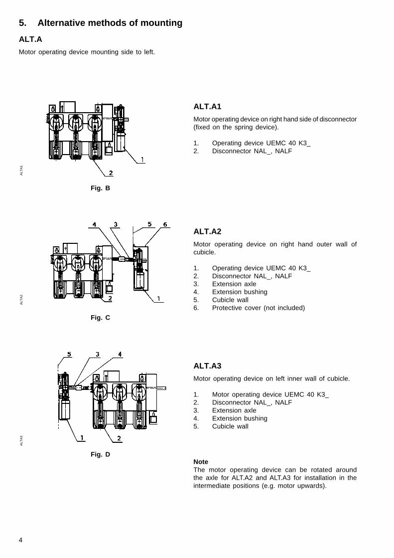
ALT.A1
Motor operating device on right hand side of disconnector(fixed on the spring device).
1. Operating device UEMC 40 K3_2. Disconnector NAL_, NALF
ALT.A2
Motor operating device on right hand outer wall ofcubicle.
1. Operating device UEMC 40 K3_2. Disconnector NAL_, NALF3. Extension axle4. Extension bushing5. Cubicle wall6. Protective cover (not included)
ALT.A3
Motor operating device on left inner wall of cubicle.
1. Motor operating device UEMC 40 K3_2. Disconnector NAL_, NALF3. Extension axle4. Extension bushing5. Cubicle wall
ALT
A1
ALT
A2
ALT
A3
5. Alternative methods of mounting
ALT.A
Motor operating device mounting side to left.
NoteThe motor operating device can be rotated aroundthe axle for ALT.A2 and ALT.A3 for installation in theintermediate positions (e.g. motor upwards).
Fig. B
Fig. C
Fig. D
5
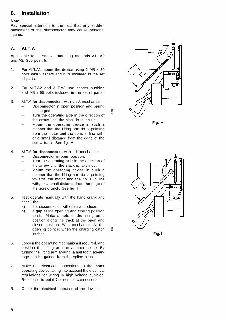
ALT.B2
Operating device on left hand outer wall of cubicle
1. Operating device UEMC 40 K3_2. Disconnector NAL_, NALF3. Extension axle4. Extension bushing5. Cubicle wall6. Protective cover (not included)
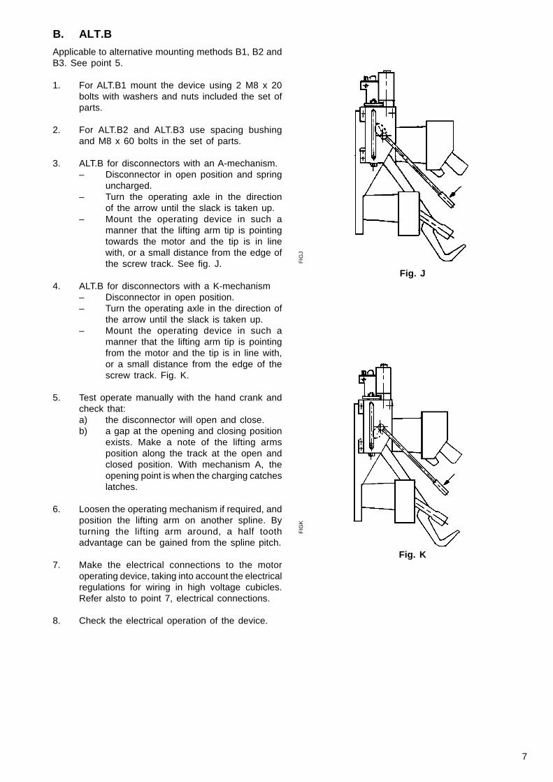
ALT.B3
Operating device on right hand inside wall of cubicle.
1. Motor operating device UEMC 40 K3_2. Disconnector NAL_, NALF3. Extension axle4. Extension bushing5. Cubicle wall
NoteThe motor operating device can be rotated aroundthe axle in ALT.B2 and ALT.B3 for installation in theintermediate positions (e.g. motor downwards).
ALT
B2
ALT
B3
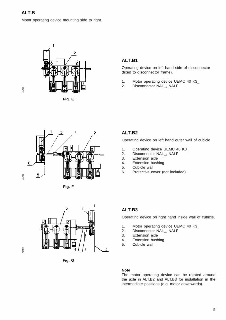
ALT.B
Motor operating device mounting side to right.
ALT.B1
Operating device on left hand side of disconnector(fixed to disconnector frame).
1. Motor operating device UEMC 40 K3_2. Disconnector NAL_, NALF
Fig. F
Fig. G
ALT
B1
Fig. E
6
6. InstallationNotePay special attention to the fact that any suddenmovement of the disconnector may cause personalinjures.
A. ALT.A
Applicable to alternative mounting methods A1, A2and A3. See point 5.
1. For ALT.A1 mount the device using 2 M8 x 20bolts with washers and nuts included in the setof parts.
2. For ALT.A2 and ALT.A3 use spacer bushingand M8 x 60 bolts included in the set of parts.
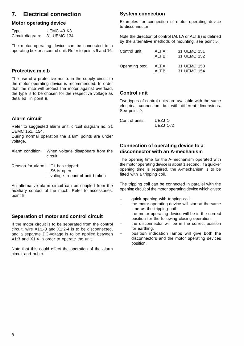
3. ALT.A for disconnectors with an A-mechanism.– Disconnector in open position and spring
uncharged.– Turn the operating axle in the direction of
the arrow until the slack is taken up.– Mount the operating device in such a
manner that the lifting arm tip is pointingfrom the motor and the tip is in line with,or a small distance from the edge of thescrew track. See fig. H.
4. ALT.A for disconnectors with a K-mechanism– Disconnector in open position.– Turn the operating axle in the direction of
the arrow until the slack is taken up.– Mount the operating device in such a
manner that the lifting arm tip is pointingtowards the motor and the tip is in linewith, or a small distance from the edge ofthe screw track. See fig. I
5. Test operate manually with the hand crank andcheck that:a) the disconnector will open and close.b) a gap at the opening and closing position
exists. Make a note of the lifting armsposition along the track at the open andclosed position. With mechanism A, theopening point is when the charging catchlatches.
6. Loosen the operating mechanism if required, andposition the lifting arm on another spline. Byturning the lifting arm around, a half tooth advan-tage can be gained from the spline pitch.
7. Make the electrical connections to the motoroperating device taking into account the electricalregulations for wiring in high voltage cubicles.Refer also to point 7, electrical connections.
8. Check the electrical operation of the device.
FIG
I
Fig. H
FIG
H
Fig. I
7
B. ALT.B
Applicable to alternative mounting methods B1, B2 andB3. See point 5.
1. For ALT.B1 mount the device using 2 M8 x 20bolts with washers and nuts included the set ofparts.
2. For ALT.B2 and ALT.B3 use spacing bushingand M8 x 60 bolts in the set of parts.
3. ALT.B for disconnectors with an A-mechanism.– Disconnector in open position and spring
uncharged.– Turn the operating axle in the direction
of the arrow until the slack is taken up.– Mount the operating device in such a
manner that the lifting arm tip is pointingtowards the motor and the tip is in linewith, or a small distance from the edge ofthe screw track. See fig. J.
4. ALT.B for disconnectors with a K-mechanism– Disconnector in open position.– Turn the operating axle in the direction of
the arrow until the slack is taken up.– Mount the operating device in such a
manner that the lifting arm tip is pointingfrom the motor and the tip is in line with,or a small distance from the edge of thescrew track. Fig. K.
5. Test operate manually with the hand crank andcheck that:a) the disconnector will open and close.b) a gap at the opening and closing position
exists. Make a note of the lifting armsposition along the track at the open andclosed position. With mechanism A, theopening point is when the charging catcheslatches.
6. Loosen the operating mechanism if required, andposition the lifting arm on another spline. Byturning the lifting arm around, a half toothadvantage can be gained from the spline pitch.
7. Make the electrical connections to the motoroperating device, taking into account the electricalregulations for wiring in high voltage cubicles.Refer alsto to point 7, electrical connections.
8. Check the electrical operation of the device.
Fig. J
FIG
J
Fig. K
FIG
K
8
7. Electrical connection
Motor operating device
Type: UEMC 40 K3Circuit diagram: 31 UEMC 134
The motor operating device can be connected to aoperating box or a control unit. Refer to points 9 and 16.
Protective m.c.b
The use of a protective m.c.b. in the supply circuit tothe motor operating device is recommended. In orderthat the mcb will protect the motor against overload,the type is to be chosen for the respective voltage asdetailed in point 9.
Alarm circuit
Refer to suggested alarm unit, circuit diagram no. 31UEMC 151...154.During normal operation the alarm points are undervoltage.
Alarm condition: When voltage disappears from thecircuit.
Reason for alarm: – F1 has tripped– S6 is open– voltage to control unit broken
An alternative alarm circuit can be coupled from theauxiliary contact of the m.c.b. Refer to accessories,point 9.
Separation of motor and control circuit
If the motor circuit is to be separated from the controlcircuit, wire X1:1-3 and X1:2-4 is to be disconnected,and a separate DC-voltage is to be applied betweenX1:3 and X1:4 in order to operate the unit.
Note that this could effect the operation of the alarmcircuit and m.b.c.
System connection
Examples for connection of motor operating deviceto disconnector:
Note the direction of control (ALT.A or ALT.B) is definedby the alternative methods of mounting, see point 5.
Control unit: ALT.A: 31 UEMC 151ALT.B: 31 UEMC 152
Operating box: ALT.A: 31 UEMC 153ALT.B: 31 UEMC 154
Control unit
Two types of control units are available with the sameelectrical connection, but with different dimensions.See point 9.
Control units: UEZJ 1-UEZJ 1-/2
Connection of operating device to adisconnector with an A-mechanism
The opening time for the A-mechanism operated withthe motor operating device is about 1 second. If a quickeropening time is required, the A-mechanism is to befitted with a tripping coil.
The tripping coil can be connected in parallel with theopening circuit of the motor operating device which gives:
– quick opening with tripping coil.– the motor operating device will start at the same
time as the tripping coil.– the motor operating device will be in the correct
position for the following closing operation.– the disconnector will be in the correct position
for earthing.– position indication lamps will give both the
disconnectors and the motor operating devicesposition.
9
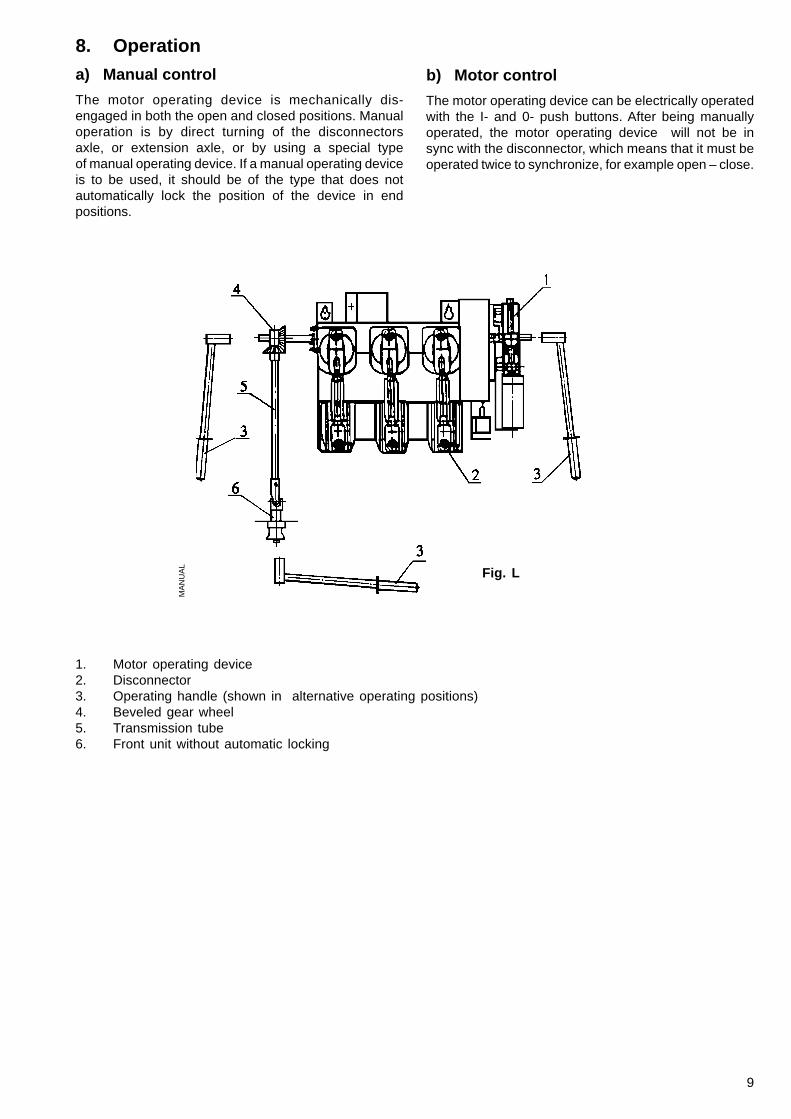
8. Operation
a) Manual control
The motor operating device is mechanically dis-engaged in both the open and closed positions. Manualoperation is by direct turning of the disconnectorsaxle, or extension axle, or by using a special typeof manual operating device. If a manual operating deviceis to be used, it should be of the type that does notautomatically lock the position of the device in endpositions.
b) Motor control
The motor operating device can be electrically operatedwith the I- and 0- push buttons. After being manuallyoperated, the motor operating device will not be insync with the disconnector, which means that it must beoperated twice to synchronize, for example open – close.
MA
NU
AL
Fig. L
1. Motor operating device2. Disconnector3. Operating handle (shown in alternative operating positions)4. Beveled gear wheel5. Transmission tube6. Front unit without automatic locking
10
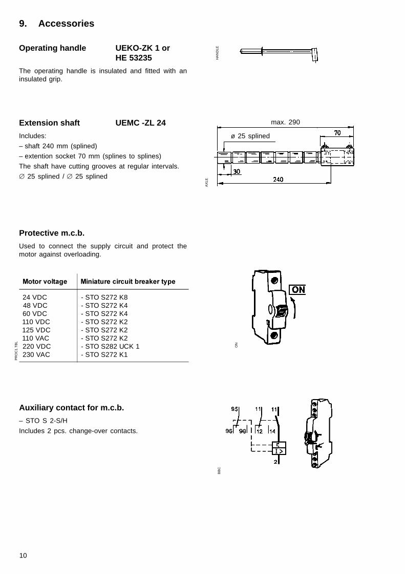
9. Accessories
Operating handle UEKO-ZK 1 orHE 53235
The operating handle is insulated and fitted with aninsulated grip.
HA
ND
LE
Protective m.c.b.
Used to connect the supply circuit and protect themotor against overloading.
Extension shaft UEMC -ZL 24
Includes:
– shaft 240 mm (splined)
– extention socket 70 mm (splines to splines)
The shaft have cutting grooves at regular intervals.
� 25 splined /�� 25 splined
AX
LE
max. 290
Auxiliary contact for m.c.b.
– STO S 2-S/H
Includes 2 pcs. change-over contacts.
ON
PR
OC
1.T
BL
BB
C
ø 25 splined
����������� ������ ������ ������������
24 VDC48 VDC60 VDC110 VDC125 VDC110 VAC220 VDC230 VAC
- STO S272 K8- STO S272 K4- STO S272 K4- STO S272 K2- STO S272 K2- STO S272 K2- STO S282 UCK 1- STO S272 K1
11
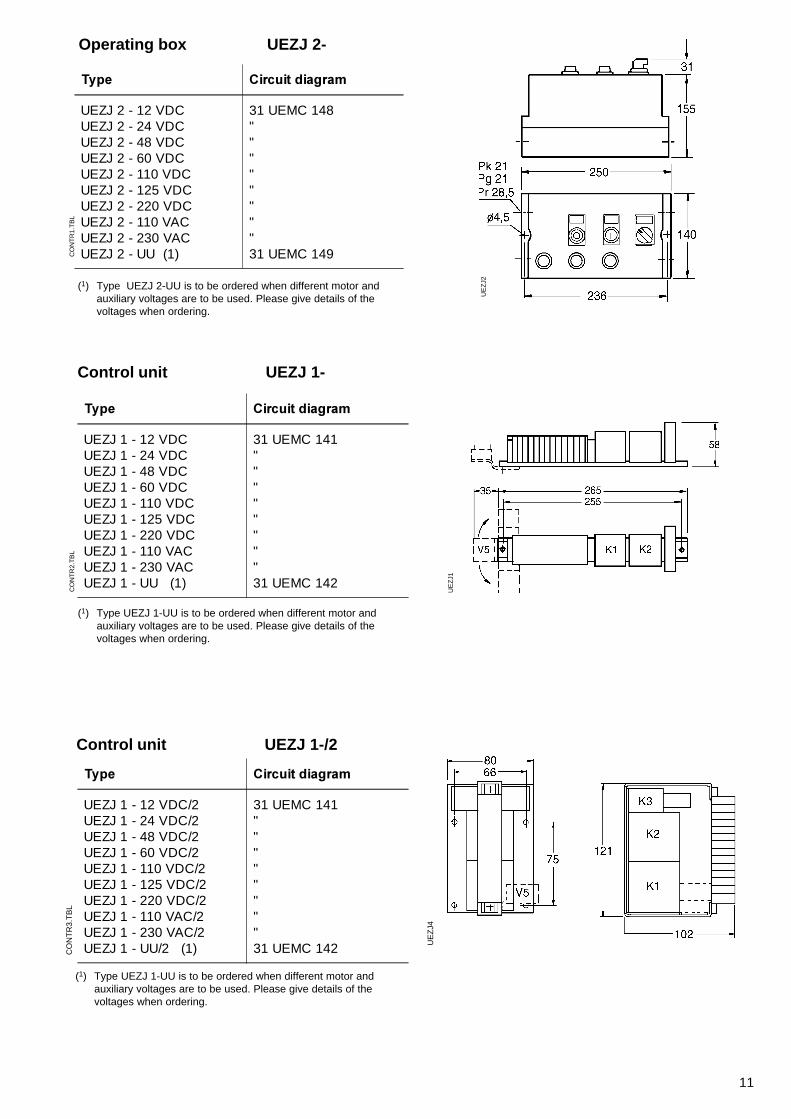
Operating box UEZJ 2-
(1) Type UEZJ 2-UU is to be ordered when different motor andauxiliary voltages are to be used. Please give details of thevoltages when ordering.
CO
NT
R1.
TB
L
UE
ZJ2
Control unit UEZJ 1-
(1) Type UEZJ 1-UU is to be ordered when different motor andauxiliary voltages are to be used. Please give details of thevoltages when ordering.
CO
NT
R2.
TB
L
UE
ZJ1
Control unit UEZJ 1-/2
(1) Type UEZJ 1-UU is to be ordered when different motor andauxiliary voltages are to be used. Please give details of thevoltages when ordering.
CO
NT
R3.
TB
L
UE
ZJ4
��� ���� ���������
UEZJ 2 - 12 VDCUEZJ 2 - 24 VDCUEZJ 2 - 48 VDCUEZJ 2 - 60 VDCUEZJ 2 - 110 VDCUEZJ 2 - 125 VDCUEZJ 2 - 220 VDCUEZJ 2 - 110 VACUEZJ 2 - 230 VACUEZJ 2 - UU (1)
31 UEMC 148""""""""31 UEMC 149
��� ���� ���������
UEZJ 1 - 12 VDCUEZJ 1 - 24 VDCUEZJ 1 - 48 VDCUEZJ 1 - 60 VDCUEZJ 1 - 110 VDCUEZJ 1 - 125 VDCUEZJ 1 - 220 VDCUEZJ 1 - 110 VACUEZJ 1 - 230 VACUEZJ 1 - UU (1)
31 UEMC 141""""""""31 UEMC 142
��� ���� ���������
UEZJ 1 - 12 VDC/2UEZJ 1 - 24 VDC/2UEZJ 1 - 48 VDC/2UEZJ 1 - 60 VDC/2UEZJ 1 - 110 VDC/2UEZJ 1 - 125 VDC/2UEZJ 1 - 220 VDC/2UEZJ 1 - 110 VAC/2UEZJ 1 - 230 VAC/2UEZJ 1 - UU/2 (1)
31 UEMC 141""""""""31 UEMC 142
12
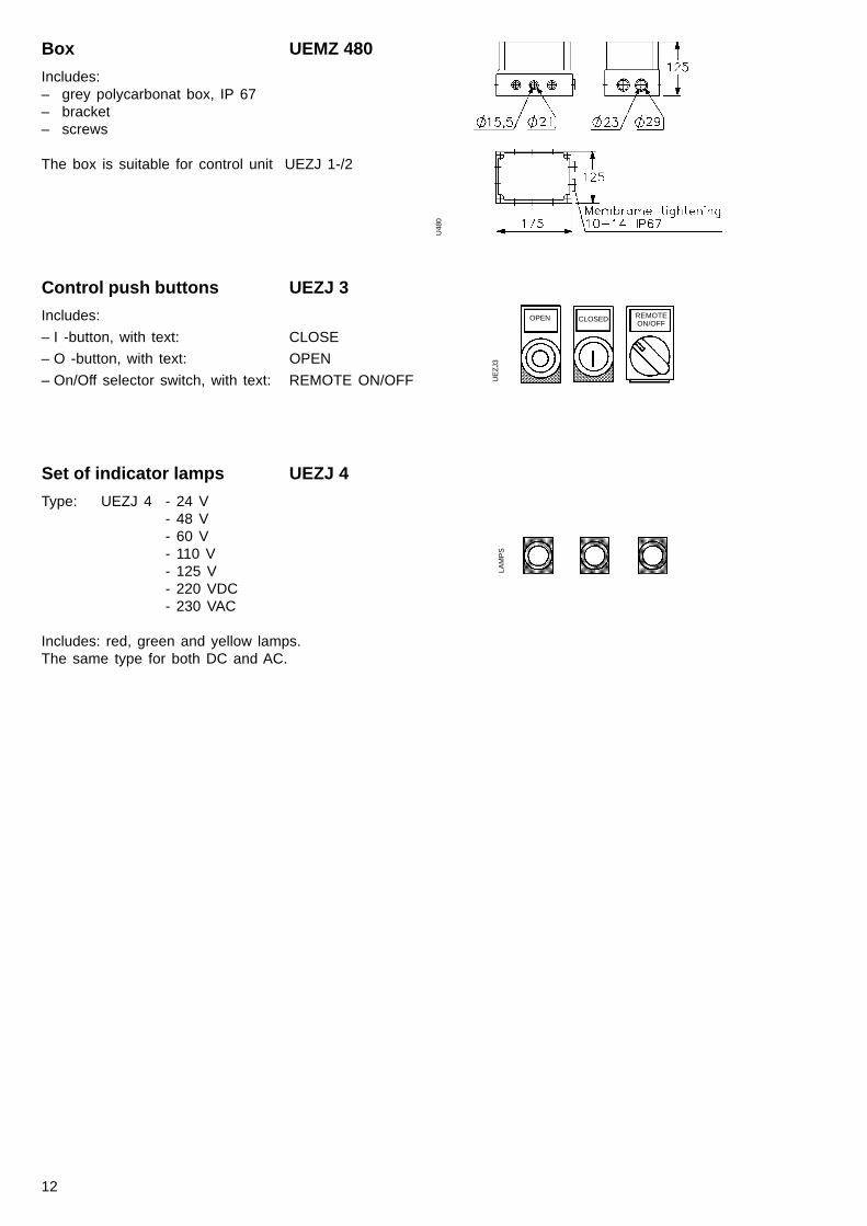
Control push buttons UEZJ 3
Includes:
– I -button, with text: CLOSE
– O -button, with text: OPEN
– On/Off selector switch, with text: REMOTE ON/OFF
Set of indicator lamps UEZJ 4
Type: UEZJ 4 - 24 V- 48 V- 60 V- 110 V- 125 V- 220 VDC- 230 VAC
Includes: red, green and yellow lamps.The same type for both DC and AC.
OPEN CLOSED REMOTEON/OFF
LAM
PS
UE
ZJ3
Box UEMZ 480
Includes:– grey polycarbonat box, IP 67– bracket– screws
The box is suitable for control unit UEZJ 1-/2
U48
0
13
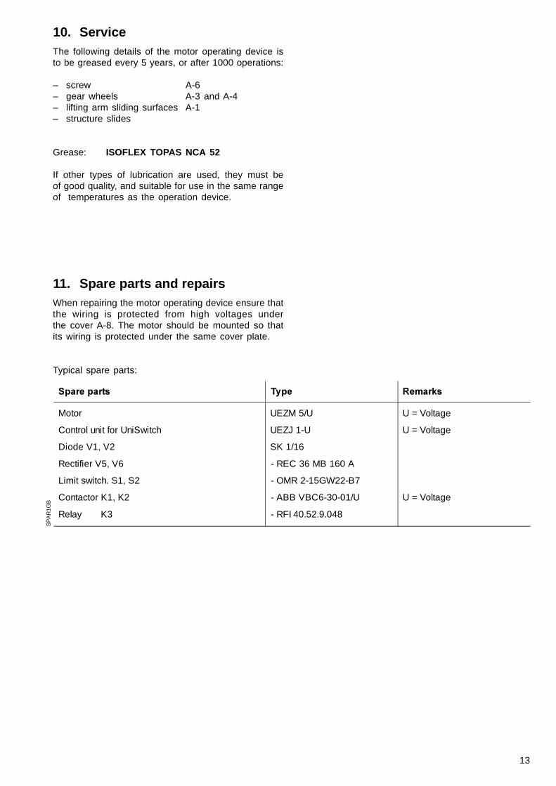
11. Spare parts and repairsWhen repairing the motor operating device ensure thatthe wiring is protected from high voltages underthe cover A-8. The motor should be mounted so thatits wiring is protected under the same cover plate.
Typical spare parts:
10. ServiceThe following details of the motor operating device isto be greased every 5 years, or after 1000 operations:
– screw A-6– gear wheels A-3 and A-4– lifting arm sliding surfaces A-1– structure slides
Grease: ISOFLEX TOPAS NCA 52
If other types of lubrication are used, they must beof good quality, and suitable for use in the same rangeof temperatures as the operation device.
SP
AR
1GB
����������� �� ����� �
Motor
Control unit for UniSwitch
Diode V1, V2
Rectifier V5, V6
Limit switch. S1, S2
Contactor K1, K2
Relay K3
UEZM 5/U
UEZJ 1-U
SK 1/16
- REC 36 MB 160 A
- OMR 2-15GW22-B7
- ABB VBC6-30-01/U
- RFI 40.52.9.048
U = Voltage
U = Voltage
U = Voltage
14
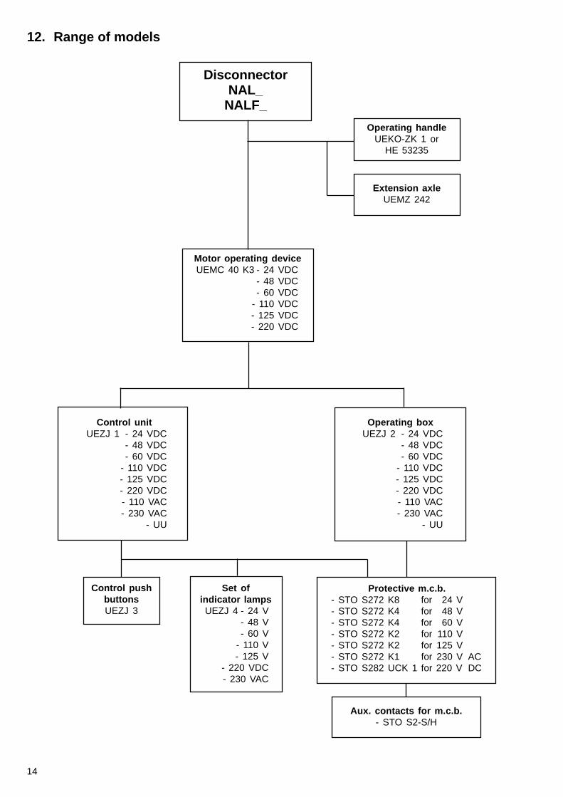
12. Range of models
DisconnectorNAL_
NALF_
Operating handleUEKO-ZK 1 or
HE 53235
Extension axleUEMZ 242
Motor operating deviceUEMC 40 K3 - 24 VDC
- 48 VDC- 60 VDC
- 110 VDC- 125 VDC- 220 VDC
Operating boxUEZJ 2 - 24 VDC
- 48 VDC- 60 VDC
- 110 VDC- 125 VDC- 220 VDC- 110 VAC- 230 VAC
- UU
Control unitUEZJ 1 - 24 VDC
- 48 VDC- 60 VDC
- 110 VDC- 125 VDC- 220 VDC- 110 VAC- 230 VAC
- UU
Control pushbuttonsUEZJ 3
Protective m.c.b.- STO S272 K8 for 24 V- STO S272 K4 for 48 V- STO S272 K4 for 60 V- STO S272 K2 for 110 V- STO S272 K2 for 125 V- STO S272 K1 for 230 V AC- STO S282 UCK 1 for 220 V DC
Aux. contacts for m.c.b.- STO S2-S/H
Set ofindicator lampsUEZJ 4 - 24 V
- 48 V- 60 V
- 110 V- 125 V
- 220 VDC- 230 VAC
15
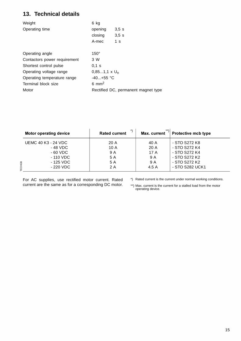
13. Technical details
Weight 6 kg
Operating time opening 3,5 s
closing 3,5 s
A-mec 1 s
Operating angle 150°
Contactors power requirement 3 W
Shortest control pulse 0,1 s
Operating voltage range 0,85...1,1 x Un
Operating temperature range -40...+55 °C
Terminal block size 6 mm2
Motor Rectified DC, permanent magnet type
For AC supplies, use rectified motor current. Ratedcurrent are the same as for a corresponding DC motor.
*) Rated current is the current under normal working conditions.
**) Max. current is the current for a stalled load from the motoroperating device.
TE
CH
GB
*) **)������������������ ������ ���� ������ ���� ����������������
UEMC 40 K3 - 24 VDC - 48 VDC - 60 VDC - 110 VDC - 125 VDC - 220 VDC
20 A10 A9 A5 A5 A2 A
40 A20 A17 A9 A9 A
4.5 A
- STO S272 K8- STO S272 K4- STO S272 K4- STO S272 K2- STO S272 K2- STO S282 UCK1
16
14. Instruction for recyclingthe product
14.1. lntroduction ................................................... 1614.2. The products casing .................................... 1614.3. Material of the product ................................ 16
14.3.1 Material of the main components .. 1614.3.2 Material of the accessories ............ 17
14.4. Recycling the product .................................. 1714.4.1 Manual demolition ........................... 1714.4.2 Mechanical crushing ....................... 1714.4.3 Eventual damaging material
and problem waste ......................... 1714.4.3.1 Directory over eventual
damaging material andproblem waste .................. 18
14.4.4 Possible recycling methods ............ 18
14.1. Introduction
This document includes instructions for recycling theproduct UEMC 40 K3. The document includes whichmaterial that are used in the products and handlinginstructions when the product is taking out of use.
The environment regulation varies from country tocountry and develops fast. Due to this it is recom-mended to contact the local customers and informthem about how to handle when the product is takingout of use.
Together with this document it should be giveninformation to the local customers about returning ofthe product that is taking out of use.
ABB Transmit Oy can give more information.
Information that is in this document is not part of anextract or deal, it supposes to be the most correctand trustful and can be changed without notice.The publisher will not take any responsibility for theconsequences.
14.2. The products casing
The product is cased in card, paper and foampiastic.The card and the paper can be recycled normally. Thefoampiastic can be i.e. used for energy production ina facility build for this purpose.
To avoid pollution when making unnecessary transportsthe manufacturer will not accept used package.Recycling has to be arranged locally according to localinstructions. Recycling is recommended when it savesrawmaterial and reduces the waste.
14.3. Material of the product
Information about the construction and main parts of theoperating device can be found in point 12, constructionfigure A. The steel parts are normally surface treated(electrical gaivanized). This does not affect the recyc-ling.
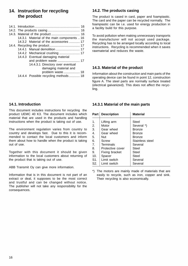
14.3.1 Material of the main parts
Part Description Material
1. Lifting arm Steel2. Motor Several *)3. Gear wheel Bronze4. Gear wheel Bronze5. Nut Bronze6. Screw Stainless steel7. Terminals Several8. Protective cover Steel9. Fixing bracket Steel10. Spacer SteelS1. Limit switch SeveralS2. Limit switch Several
*) The motors are mainly made of materials that areeasily to recycle, such as iron, copper and sink.Their recycling is also economically.
17
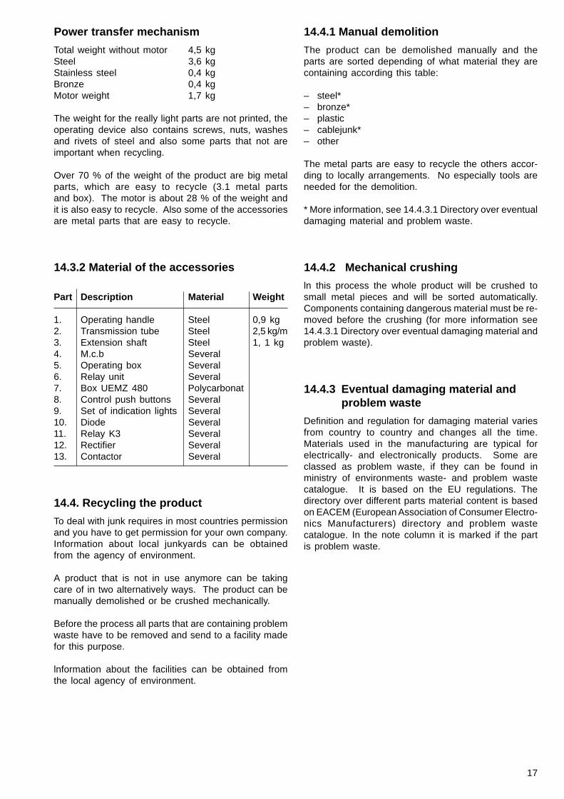
14.3.2 Material of the accessories
Part Description Material Weight
1. Operating handle Steel 0,9 kg2. Transmission tube Steel 2,5 kg/m3. Extension shaft Steel 1, 1 kg4. M.c.b Several5. Operating box Several6. Relay unit Several7. Box UEMZ 480 Polycarbonat8. Control push buttons Several9. Set of indication lights Several10. Diode Several11. Relay K3 Several12. Rectifier Several13. Contactor Several
14.4. Recycling the product
To deal with junk requires in most countries permissionand you have to get permission for your own company.Information about local junkyards can be obtainedfrom the agency of environment.
A product that is not in use anymore can be takingcare of in two alternatively ways. The product can bemanually demolished or be crushed mechanically.
Before the process all parts that are containing problemwaste have to be removed and send to a facility madefor this purpose.
lnformation about the facilities can be obtained fromthe local agency of environment.
Power transfer mechanism
Total weight without motor 4,5 kgSteel 3,6 kgStainless steel 0,4 kgBronze 0,4 kgMotor weight 1,7 kg
The weight for the really light parts are not printed, theoperating device also contains screws, nuts, washesand rivets of steel and also some parts that not areimportant when recycling.
Over 70 % of the weight of the product are big metalparts, which are easy to recycle (3.1 metal partsand box). The motor is about 28 % of the weight andit is also easy to recycle. Also some of the accessoriesare metal parts that are easy to recycle.
14.4.1 Manual demolition
The product can be demolished manually and theparts are sorted depending of what material they arecontaining according this table:
– steel*– bronze*– plastic– cablejunk*– other
The metal parts are easy to recycle the others accor-ding to locally arrangements. No especially tools areneeded for the demolition.
* More information, see 14.4.3.1 Directory over eventualdamaging material and problem waste.
14.4.2 Mechanical crushing
ln this process the whole product will be crushed tosmall metal pieces and will be sorted automatically.Components containing dangerous material must be re-moved before the crushing (for more information see14.4.3.1 Directory over eventual damaging material andproblem waste).
14.4.3 Eventual damaging material andproblem waste
Definition and regulation for damaging material variesfrom country to country and changes all the time.Materials used in the manufacturing are typical forelectrically- and electronically products. Some areclassed as problem waste, if they can be found inministry of environments waste- and problem wastecatalogue. It is based on the EU regulations. Thedirectory over different parts material content is basedon EACEM (European Association of Consumer Electro-nics Manufacturers) directory and problem wastecatalogue. In the note column it is marked if the partis problem waste.
18
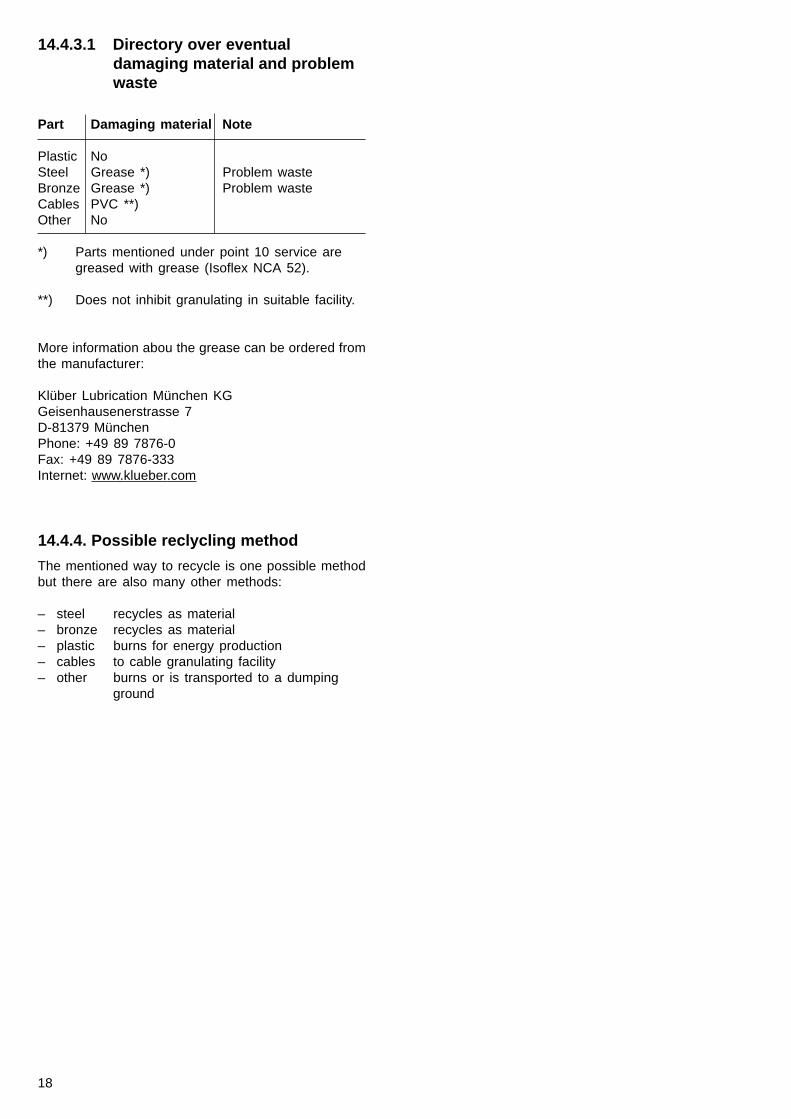
14.4.3.1 Directory over eventualdamaging material and problemwaste
Part Damaging material Note
Plastic NoSteel Grease *) Problem wasteBronze Grease *) Problem wasteCables PVC **)Other No
*) Parts mentioned under point 10 service aregreased with grease (Isoflex NCA 52).
**) Does not inhibit granulating in suitable facility.
More information abou the grease can be ordered fromthe manufacturer:
Klüber Lubrication München KGGeisenhausenerstrasse 7D-81379 MünchenPhone: +49 89 7876-0Fax: +49 89 7876-333Internet: www.klueber.com
14.4.4. Possible reclycling method
The mentioned way to recycle is one possible methodbut there are also many other methods:
– steel recycles as material– bronze recycles as material– plastic burns for energy production– cables to cable granulating facility– other burns or is transported to a dumping
ground
19
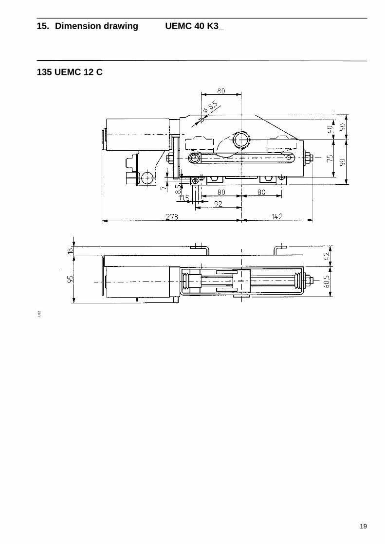
U12
135 UEMC 12 C
15. Dimension drawing UEMC 40 K3_
20
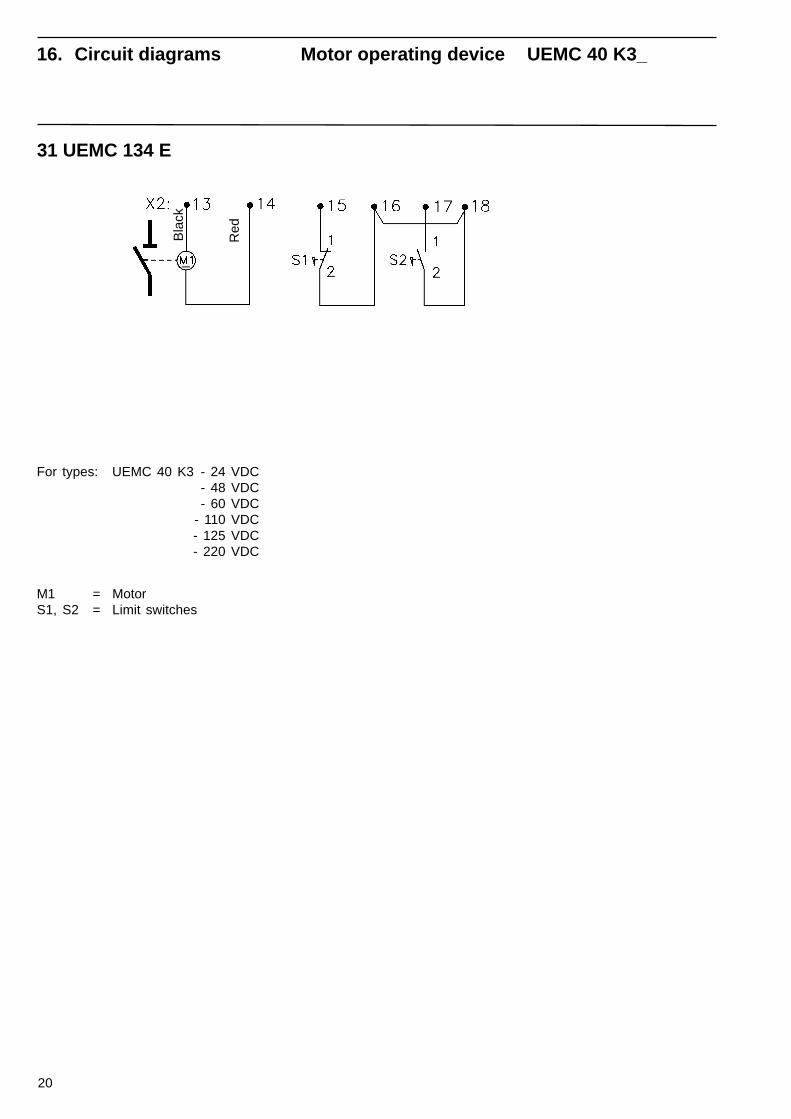
31 UEMC 134 E
For types: UEMC 40 K3 - 24 VDC- 48 VDC- 60 VDC
- 110 VDC- 125 VDC- 220 VDC
Bla
ck
Red
M1 = MotorS1, S2 = Limit switches
16. Circuit diagrams Motor operating device UEMC 40 K3_
21
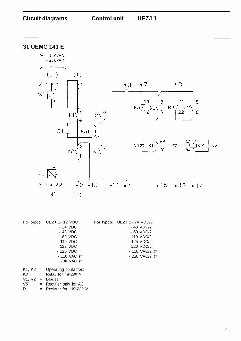
31 UEMC 141 E
For types: UEZJ 1- 12 VDC- 24 VDC- 48 VDC- 60 VDC
- 110 VDC- 125 VDC- 220 VDC- 110 VAC (*- 230 VAC (*
K1, K2 = Operating contactorsK3 = Relay for 48-230 VV1, V2 = DiodesV5 = Rectifier only for ACR1 = Resistor for 110-230 V
Circuit diagrams Control unit UEZJ 1_
For types: UEZJ 1- 24 VDC/2- 48 VDC/2- 60 VDC/2
- 110 VDC/2- 125 VDC/2- 220 VDC/2- 110 VAC/2 (*- 230 VAC/2 (*
22
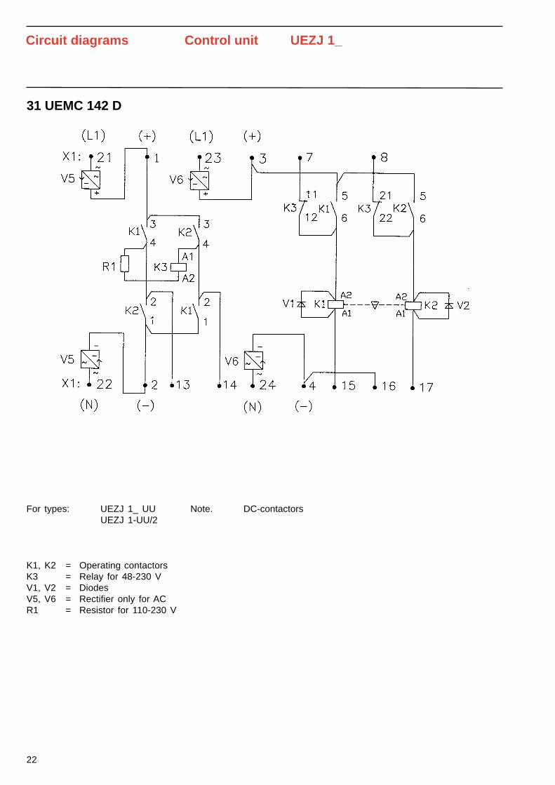
31 UEMC 142 D
For types: UEZJ 1_ UUUEZJ 1-UU/2
K1, K2 = Operating contactorsK3 = Relay for 48-230 VV1, V2 = DiodesV5, V6 = Rectifier only for ACR1 = Resistor for 110-230 V
Circuit diagrams Control unit UEZJ 1_
Note. DC-contactors
23
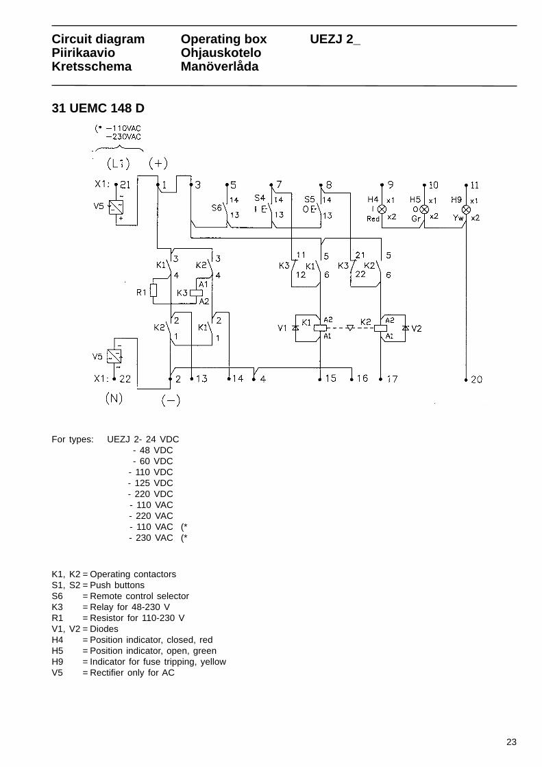
31 UEMC 148 D
For types: UEZJ 2- 24 VDC- 48 VDC- 60 VDC
- 110 VDC- 125 VDC- 220 VDC- 110 VAC- 220 VAC- 110 VAC (*- 230 VAC (*
K1, K2 = Operating contactorsS1, S2 = Push buttonsS6 = Remote control selectorK3 = Relay for 48-230 VR1 = Resistor for 110-230 VV1, V2 = DiodesH4 = Position indicator, closed, redH5 = Position indicator, open, greenH9 = Indicator for fuse tripping, yellowV5 = Rectifier only for AC
Circuit diagram Operating box UEZJ 2_Piirikaavio OhjauskoteloKretsschema Manöverlåda
24
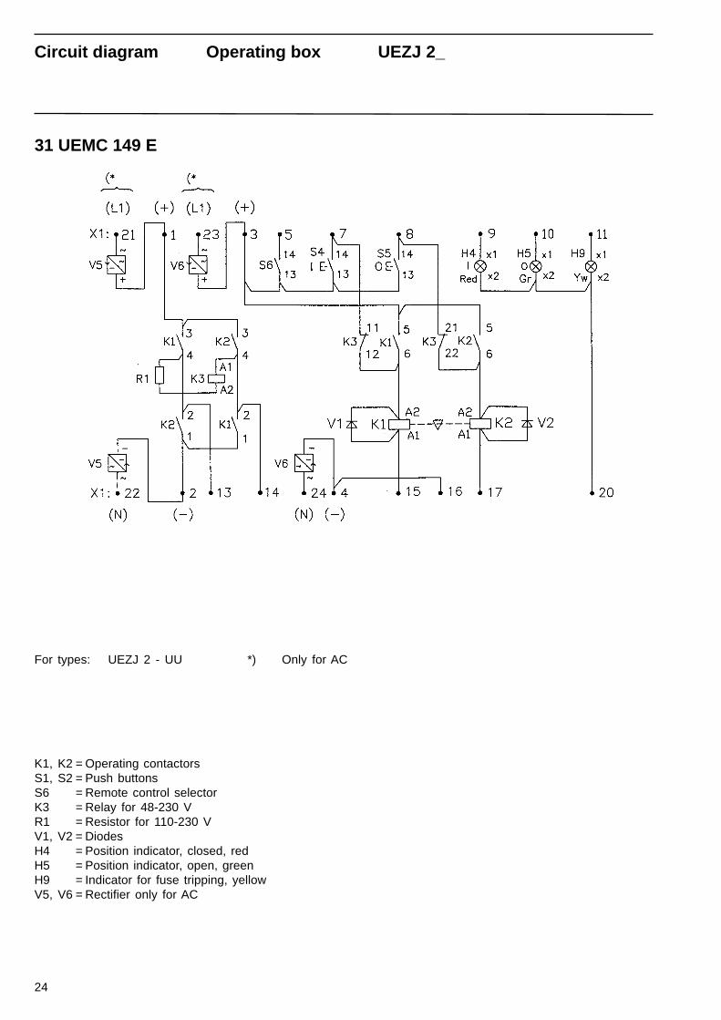
31 UEMC 149 E
For types: UEZJ 2 - UU
K1, K2 = Operating contactorsS1, S2 = Push buttonsS6 = Remote control selectorK3 = Relay for 48-230 VR1 = Resistor for 110-230 VV1, V2 = DiodesH4 = Position indicator, closed, redH5 = Position indicator, open, greenH9 = Indicator for fuse tripping, yellowV5, V6 = Rectifier only for AC
Circuit diagram Operating box UEZJ 2_
*) Only for AC
25
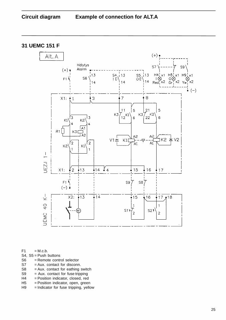
31 UEMC 151 F
F1 = M.c.b.S4, S5 = Push buttonsS6 = Remote control selectorS7 = Aux. contact for disconn.S8 = Aux. contact for eathing switchS9 = Aux. contact for fuse trippingH4 = Position indicator, closed, redH5 = Position indicator, open, greenH9 = Indicator for fuse tripping, yellow
Circuit diagram Example of connection for ALT.A
26
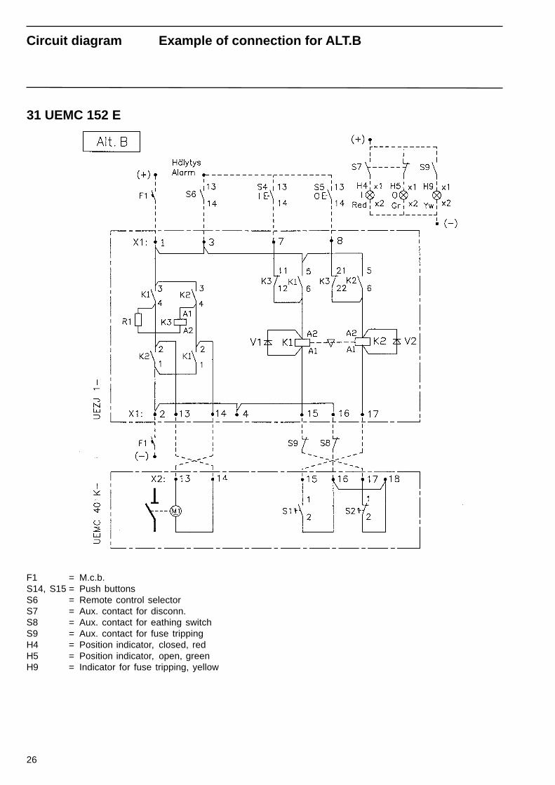
31 UEMC 152 E
F1 = M.c.b.S14, S15 = Push buttonsS6 = Remote control selectorS7 = Aux. contact for disconn.S8 = Aux. contact for eathing switchS9 = Aux. contact for fuse trippingH4 = Position indicator, closed, redH5 = Position indicator, open, greenH9 = Indicator for fuse tripping, yellow
Circuit diagram Example of connection for ALT.B
27
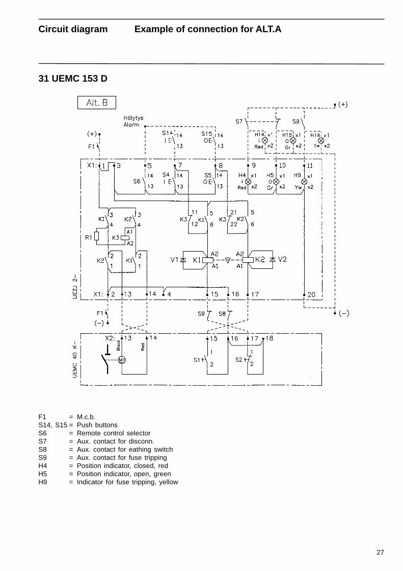
31 UEMC 153 D
F1 = M.c.b.S14, S15 = Push buttonsS6 = Remote control selectorS7 = Aux. contact for disconn.S8 = Aux. contact for eathing switchS9 = Aux. contact for fuse trippingH4 = Position indicator, closed, redH5 = Position indicator, open, greenH9 = Indicator for fuse tripping, yellow
Circuit diagram Example of connection for ALT.A
28
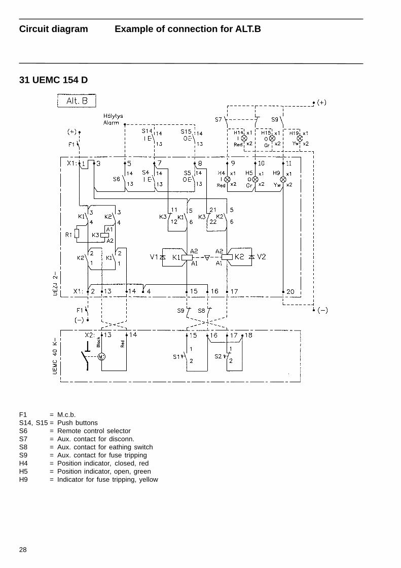
31 UEMC 154 D
F1 = M.c.b.S14, S15 = Push buttonsS6 = Remote control selectorS7 = Aux. contact for disconn.S8 = Aux. contact for eathing switchS9 = Aux. contact for fuse trippingH4 = Position indicator, closed, redH5 = Position indicator, open, greenH9 = Indicator for fuse tripping, yellow
Circuit diagram Example of connection for ALT.B

29

04/2002ABB60
ABB Sp. z o.o.ul. Bitwy Warszawskiej 1920r. nr 18Division ZWAR in Przasnyszaddress: 59, Leszno Str.
06 - 300 PrzasnyszPhone: +48 22 51 52 838
+48 22 51 52 831Fax: +48 22 51 52 659e-mail: [email protected]
ABB is working to continuous improve the products.Therefore we reserve the right to change desing,dimension and data without prior notice.
www.abb.com