motor linearity
TRANSCRIPT

Voice Coil 2006 1
The Audio TechnologyAuthority
Article prepared for www.audioXpress.com
Searching For Motor Linearity Searching For Motor Linearity By Steve Mowry Searching For Motor Linearity By Steve Mowry Searching For Motor Linearity By Steve Mowry Searching For Motor Linearity By Steve Mowry Searching For Motor Linearity
Most transducer engineers agree that the motor assembly is a major source of nonlinearity within audio transducers. This article focuses on displacement and temperature related nonlinearities, while looking to identify and suggest alternative materials and topology that can improve transducer motor assembly linearity. Admittedly, linearity could be further improved by utilizing copper or aluminum shorting rings and/or pole caps; however, the examples are intended to pro-vide meaningful information but remain simple; no shorting rings or bobbins were included within the models.
FERROMAGNETIC & NONFERROUS MATERIALS The most common ferromagnetic material utilized in
audio transducer motor assemblies is low carbon cold rolled annealed steel, C1010 (0.010% carbon typical) or better. This material is typically cold forged into the desired shape and then plated with a chromate over zinc process to prevent oxidation/rust. In the case of large and/or very high-perfor-mance transducers, the motor’s steel parts may be carefully CNC machined to close tolerances before plating. Figure 1illustrates the BH characteristics for C1010.
You can see in Fig. 1 that C1010 steel conducts magnetic Fig. 1 that C1010 steel conducts magnetic Fig. 1flux quite well up to a density of 1.5 tesla (T) and can be pushed to a density of 2.0T. The steel “shuts off” at 2.2T and begins to look like air to the flux.
There is a high-performance alternative to C1010 steel. The material is called Hiperco 50A—Carpenter Hiperco Alloy 50 is an iron-cobalt soft magnetic alloy (0.004% C, 0.05% Mn, 0.05% Si, 48.75% Co, 2.00% V, Bal. Fe) intended for com-mercial applications requiring high strength and well-suited to audio transducer motor assembly applications. Hiperco 50A is available in a bar larger than 0.50 round. Motor assembly round. Motor assembly parts should be CNC machined at a slow cutting rate.
Figure 2 contains the BH characteristics for Hiperco 50A, Figure 2 contains the BH characteristics for Hiperco 50A, Figure 2which is sometimes also marketed under the brand name PERMENDUR 2V at 25°C. Hiperco 50A’s magnetic proper-ties are excellent. Flux is conducted well to a density well above 2.0T. Please note the values of H on the y-axis in comparing Fig. 2 to Fig. 2 to Fig. 2 Fig. 1.Fig. 1.Fig. 1
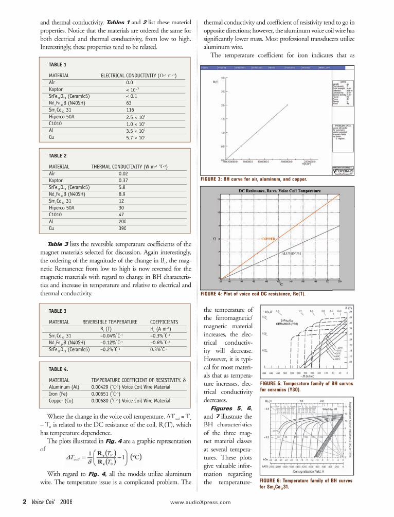
The most common nonferrous material is air. Figure 3contains the BH characteristics for all nonferrous materials, including air, polymers, aluminum, and copper.
The BH characteristics illustrated in Fig. 3 are assumed Fig. 3 are assumed Fig. 3constant.
ELECTRO-MAGNETIC & TEMPERATURE RELATED PROPERTIES
Two other material properties of interest are the electrical
FIGURE 1: BH curve for C1010 steel at 25° C.
FIGURE 2: BH curve for Hiperco 50A at 25° C.
2 Voice Coil 2006 www.audioXpress .com
and thermal conductivity. Tables 1 and Tables 1 and Tables 1 2 list these material 2 list these material 2properties. Notice that the materials are ordered the same for both electrical and thermal conductivity, from low to high. Interestingly, these properties tend to be related.
Table 3 lists the reversible temperature coefficients of the Table 3 lists the reversible temperature coefficients of the Table 3magnet materials selected for discussion. Again interestingly, the ordering of the magnitude of the change in Br, the mag-netic Remanence from low to high is now reversed for the magnetic materials with regard to change in BH characteris-tics and increase in temperature and relative to electrical and thermal conductivity.
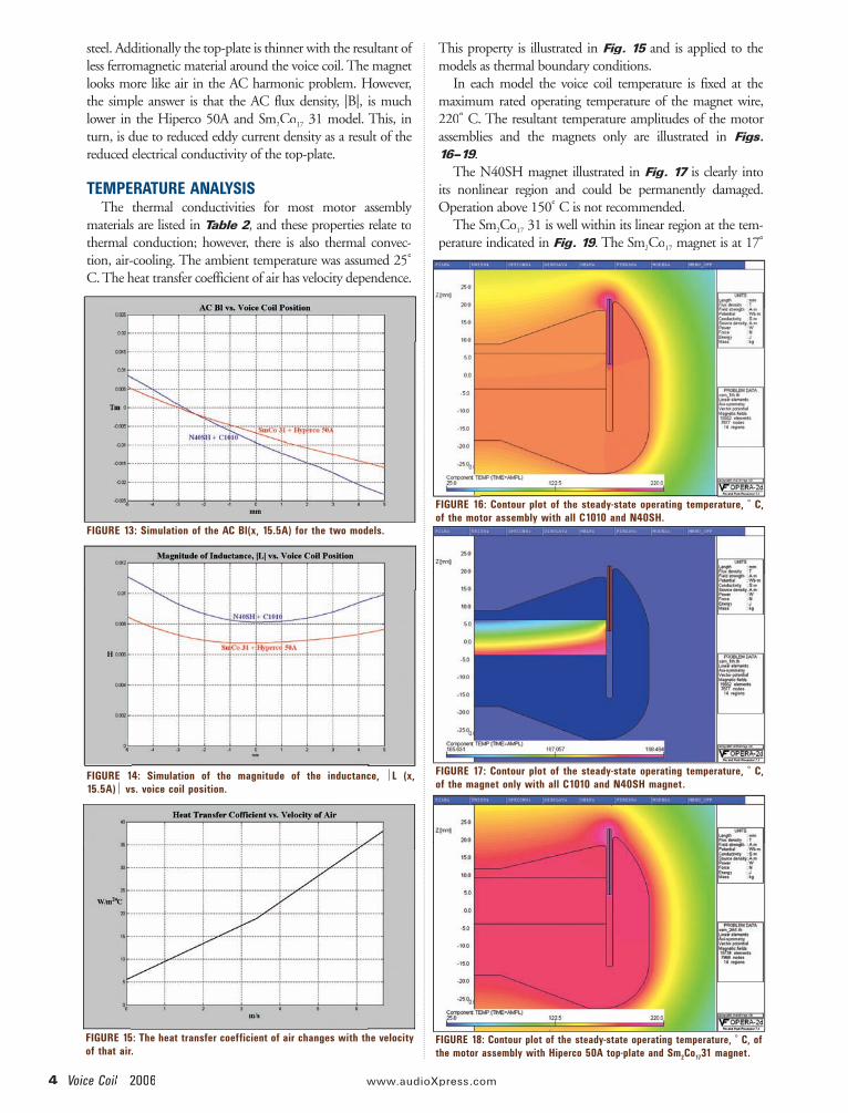
Where the change in the voice coil temperature, ∆TcoilTcoilT = Tcoil = Tcoil v
– T0 is related to the DC resistance of the coil, Re is related to the DC resistance of the coil, Re is related to the DC resistance of the coil, R (T), which has temperature dependence.
The plots illustrated in Fig. 4 are a graphic representation Fig. 4 are a graphic representation Fig. 4of
With regard to Fig. 4, all the models utilize aluminum Fig. 4, all the models utilize aluminum Fig. 4wire. The temperature issue is a complicated problem. The
thermal conductivity and coefficient of resistivity tend to go in opposite directions; however, the aluminum voice coil wire has significantly lower mass. Most professional transducers utilize aluminum wire.
The temperature coefficient for iron indicates that as
the temperature of the ferromagnetic/magnetic material increases, the elec-trical conductiv-ity will decrease. However, it is typi-cal for most materi-als that as tempera-ture increases, elec-trical conductivity decreases.
Figures 5, Figures 5, Figures 5 6, 6, 6and 7 illustrate the BH characteristics of the three mag-net material classes at several tempera-tures. These plots give valuable infor-mation regarding the temperature-
TABLE 1
MATERIAL ELECTRICAL CONDUCTIVITY (MATERIAL ELECTRICAL CONDUCTIVITY (MATERIAL Ω–1 m–1) Air 0.0 Kapton < 10–7
SrFe12O19 (Ceramic5) < 0.1 Nd2Fe14B (N40SH) 63 Sm2Co17 31 116 Hiperco 50A 2.5 × 10⁶
C1010 1.0 × 10⁷
Al 3.5 × 10⁷
Cu 5.7 × 10⁷
TABLE 2
MATERIAL THERMAL CONDUCTIVITY (W m–1 °C–1) Air 0.02 Kapton 0.37 SrFe12O19 (Ceramic5) 5.8 Nd2Fe14B (N40SH) 8.9 Sm2Co17 31 12 Hiperco 50A 30 C1010 47 Al 200Cu 390
TABLE 3
MATERIAL REVERSIBLE TEMPERATURE COEFFICIENTS Br (T) Hr (T) Hr c (A mc (A mc
–1) Sm2Co17 31 –0.04%°C–1 –0.3%°C–1
Nd2Fe14B (N40SH) –0.12%°C–1 –0.6%°C–1
SrFe12O19 (Ceramic5) –0.2%°C–1 0.3%°C–1
TABLE 4.
MATERIAL TEMPERATURE COEFFICIENT OF RESISTIVITY, δAluminum (Al) 0.00429 (°C–1) Voice Coil Wire Material Iron (Fe) 0.00651 (°C–1) Copper (Cu) 0.00680 (°C–1) Voice Coil Wire Material
FIGURE 3: BH curve for air, aluminum, and copper.
FIGURE 4: Plot of voice coil DC resistance, Re(T).
FIGURE 5: Temperature family of BH curves for ceramics (Y30).
FIGURE 6: Temperature family of BH curves for Sm2Co1731.

Voice Coil 2006 3
related robustness and motor assembly linearity related to changes in magnet temperature.
The BH char-acteristics ceramic magnets actually become linear at high temperature; however, the Br is sig-r is sig-r
nificantly reduced.The magnet illus-
trated in Fig. 6 is of the highest quality; however, it is also the Fig. 6 is of the highest quality; however, it is also the Fig. 6highest cost.
Only the samarium cobalt and neodymium iron boron BH characteristics are linear; however, what is intriguing is the samarium cobalt’s BH characteristics stay linear to above 200°C, while the neodymium iron boron’s BH characteristics begin to become nonlinear at approximately 100°C. This can be observed by examining Figs. 6 and Figs. 6 and Figs. 6 7. 7. 7
ELECTRO-MAGNETIC ANALYSIS Essentially the difference between the geometry in the
models illustrated in Figs. 8 and Figs. 8 and Figs. 8 9 is that the Sm9 is that the Sm9 2Co17 31 17 31 17
magnet in Fig. 9 is 3.0mm thicker and the Hiperco 50A top-Fig. 9 is 3.0mm thicker and the Hiperco 50A top-Fig. 9plate is 3.0mm thinner. The cups and voice coils are identical
but the voice coil is positioned relative to the top-plate center. The blue trace in Fig. 10 indicates an Xmax Fig. 10 indicates an Xmax Fig. 10 ≈ ±5.0mm,
based on 0.82Bl(0) ≈ Bl (±Xmax). The red trace is signifi-cantly more linear, where 0.88Bl (0) ≈ Bl(±5.0mm) but the peak value of Bl is down by about 8% (~0.67dB).
Ideally the trace(s) in Fig. 13 would pass through the ori-Fig. 13 would pass through the ori-Fig. 13gin, (0,0); however, due to the geometric and material asym-metries, these curves are asymmetric. The amplitudes are small but the red’s results are more linear.
The inductance simulations illustrated in Fig. 14 again Fig. 14 again Fig. 14show the improvement in linearity results for the Hiperco 50A top-plate and the Sm2Co17 31 magnet, but why? The 17 31 magnet, but why? The 17
electrical conductivity of Hiperco 50A is only 25% of C1010
FIGURE 8: Contour plot of B with the DC flux lines overdrawn for all C1010 with N40SH.
FIGURE 10: Simulation of B1(x) for the two models.
FIGURE 11: Contour plot of B with the AC flux lines overdrawn for all C1010 with N40SH at 50Hz.
FIGURE 12: Contour plot of B with the AC flux lines overdrawn for Hiperco 50A with Sm2Co1731 at 50Hz.
FIGURE 9: Contour plot of B with the DC flux lines overdrawn for Hiperco 50A with Sm2Co1731.
FIGURE 7: Temperature family of BH curves for Nd2Fe14B (N40SH).
4 Voice Coil 2006 www.audioXpress .com
steel. Additionally the top-plate is thinner with the resultant of less ferromagnetic material around the voice coil. The magnet looks more like air in the AC harmonic problem. However, the simple answer is that the AC flux density, |B|, is much lower in the Hiperco 50A and Sm2Co17 31 model. This, in 17 31 model. This, in 17
turn, is due to reduced eddy current density as a result of the reduced electrical conductivity of the top-plate.
TEMPERATURE ANALYSIS The thermal conductivities for most motor assembly
materials are listed in Table 2, and these properties relate to Table 2, and these properties relate to Table 2thermal conduction; however, there is also thermal convec-tion, air-cooling. The ambient temperature was assumed 25°C. The heat transfer coefficient of air has velocity dependence.
This property is illustrated in Fig. 15 and is applied to the Fig. 15 and is applied to the Fig. 15models as thermal boundary conditions.
In each model the voice coil temperature is fixed at the maximum rated operating temperature of the magnet wire, 220° C. The resultant temperature amplitudes of the motor assemblies and the magnets only are illustrated in Figs. 16–19.16–19.16–19
The N40SH magnet illustrated in Fig. 17 is clearly into Fig. 17 is clearly into Fig. 17its nonlinear region and could be permanently damaged. Operation above 150° C is not recommended.
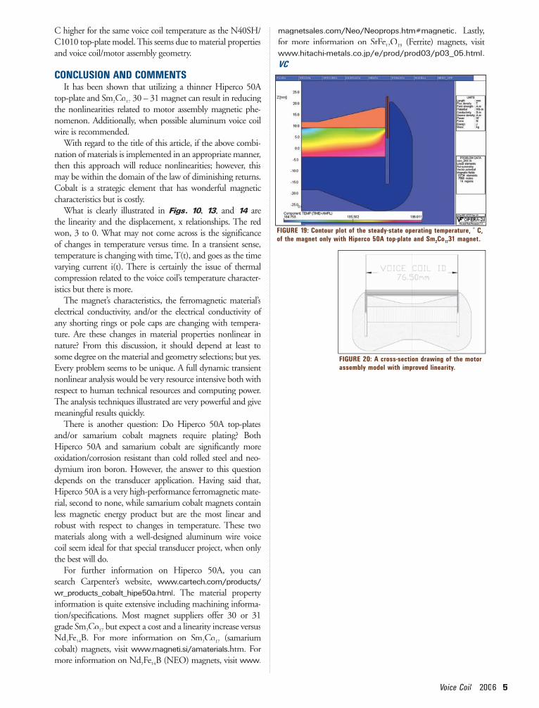
The Sm2Co17 31 is well within its linear region at the tem-17 31 is well within its linear region at the tem-17
perature indicated in Fig. 19. The SmFig. 19. The SmFig. 19 2Co17 magnet is at 1717 magnet is at 1717 °
FIGURE 13: Simulation of the AC Bl(x, 15.5A) for the two models.
FIGURE 14: Simulation of the magnitude of the inductance, L (x, 15.5A) vs. voice coil position.
FIGURE 16: Contour plot of the steady-state operating temperature, ° C, of the motor assembly with all C1010 and N40SH.
FIGURE 15: The heat transfer coefficient of air changes with the velocity of that air.
FIGURE 17: Contour plot of the steady-state operating temperature, ° C, of the magnet only with all C1010 and N40SH magnet.
FIGURE 18: Contour plot of the steady-state operating temperature, ° C, of the motor assembly with Hiperco 50A top-plate and Sm2Co1731 magnet.
Voice Coil 2006 5
C higher for the same voice coil temperature as the N40SH/C1010 top-plate model. This seems due to material properties and voice coil/motor assembly geometry.
CONCLUSION AND COMMENTS It has been shown that utilizing a thinner Hiperco 50A
top-plate and Sm2Co17 30 – 31 magnet can result in reducing 17 30 – 31 magnet can result in reducing 17
the nonlinearities related to motor assembly magnetic phe-nomenon. Additionally, when possible aluminum voice coil wire is recommended.
With regard to the title of this article, if the above combi-nation of materials is implemented in an appropriate manner, then this approach will reduce nonlinearities; however, this may be within the domain of the law of diminishing returns. Cobalt is a strategic element that has wonderful magnetic characteristics but is costly.
What is clearly illustrated in Figs. 10, Figs. 10, Figs. 10 13, and 13, and 13 14 are 14 are 14the linearity and the displacement, x relationships. The red won, 3 to 0. What may not come across is the significance of changes in temperature versus time. In a transient sense, temperature is changing with time, T(t), and goes as the time varying current i(t). There is certainly the issue of thermal compression related to the voice coil’s temperature character-istics but there is more.
The magnet’s characteristics, the ferromagnetic material’s electrical conductivity, and/or the electrical conductivity of any shorting rings or pole caps are changing with tempera-ture. Are these changes in material properties nonlinear in nature? From this discussion, it should depend at least to some degree on the material and geometry selections; but yes. Every problem seems to be unique. A full dynamic transient nonlinear analysis would be very resource intensive both with respect to human technical resources and computing power. The analysis techniques illustrated are very powerful and give meaningful results quickly.
There is another question: Do Hiperco 50A top-plates and/or samarium cobalt magnets require plating? Both Hiperco 50A and samarium cobalt are significantly more oxidation/corrosion resistant than cold rolled steel and neo-dymium iron boron. However, the answer to this question depends on the transducer application. Having said that, Hiperco 50A is a very high-performance ferromagnetic mate-rial, second to none, while samarium cobalt magnets contain less magnetic energy product but are the most linear and robust with respect to changes in temperature. These two materials along with a well-designed aluminum wire voice coil seem ideal for that special transducer project, when only the best will do.
For further information on Hiperco 50A, you can search Carpenter’s website, www.cartech.com/products/wr_products_cobalt_hipe50a.html. The material property information is quite extensive including machining informa-tion/specifications. Most magnet suppliers offer 30 or 31 grade Sm2Co17 but expect a cost and a linearity increase versus 17 but expect a cost and a linearity increase versus 17
Nd2Nd2Nd Fe14B. For more information on Sm2Co17 (samarium 17 (samarium 17
cobalt) magnets, visit www.magneti.si/amaterials.htm. For more information on Nd2more information on Nd2more information on Nd Fe14B (NEO) magnets, visit www.
magnetsales.com/Neo/Neoprops.htm#magnetic. Lastly, for more information on SrFe12O19 (Ferrite) magnets, visit www.hitachi-metals.co.jp/e/prod/prod03/p03_05.html. VC
FIGURE 19: Contour plot of the steady-state operating temperature, ° C, of the magnet only with Hiperco 50A top-plate and Sm2Co1731 magnet.
FIGURE 20: A cross-section drawing of the motor assembly model with improved linearity.