motor failure on the 9x, c and m-series milling machines the...b. with the voltmeter, check the...
TRANSCRIPT

How to Determine the Cause of a Motor Failure 9x, c, M-Series
1 / 8 HT-Determine Motor Failure 9x, C,M-Series Author: LPKF/Chris Ware Valid Since: 8/20/2011
© LPKF
Motor Failure on the 9x, C and M-Series Milling Machines
1. Requirements a. Voltmeter b. 3mm Allen wrench c. 4mm Allen wrench d. #3 phillips screwdriver
2. Start the motor a. In the tool select menu, select a random tool. b. Insert the tool into the collet. c. Move the machine away from the exchange position. d. Start the motor.
3. Test motor voltage at spindle. a. Remove the 3 pin circular connector from the spindle motor. b. With the voltmeter, test each pin for voltage.
60K/100 motor 40K motor
20K/30K motor c. The voltage readings should be as follows:
i. 20K motors: 76 volts DC ii. 30K motors: 36 volts DC
iii. 40K (ec) motor: 6 volts DC 1. EC motors have 8 leads, test leads 1,3,5 and 8
iv. 60K/100 motors: 24 volts AC

How to Determine the Cause of a Motor Failure 9x, c, M-Series
2 / 8 HT-Determine Motor Failure 9x, C,M-Series Author: LPKF/Chris Ware Valid Since: 8/20/2011
© LPKF
Note: Place the black lead of the voltmeter to ground. Ground can be a screw on the out-side of the machine. Place the red lead onto the test point as directed. d. f the correct voltage is present, replace the spindle motor.
i. Contact LPKF technical support to issue an RMA number and give part infor-mation.
Note: LPKF will need a purchase order or credit card order before the board can be shipped. e. If the voltage is not present, reconnect the connector and go to step 4.
4. Test motor voltage at the controller box. a. Remove the 5 pin circular connector from the controller box, located to the left of the
main power switch.
30K EC/40K/60K/100K motors 20/30K DC motors b. With the voltmeter, check the voltage on pins 1, 3 and 5. (9-oclock, noon and 3-oclock)
If testing a 20K or 30K DC motor, use pins X and Y on the head cable. c. The voltage readings should be as follows:
i. 20K motors: 76 volts DC ii. 30K/40K motors: 36 volts DC
iii. 60K/100K motors: 24 volts AC Note: if testing a DC motor, pin 1 will read @36 volts DC, pins 3 and 5 will read 0.
d. If the correct voltage is present, go to step 5. e. If the correct voltage is not present, go to step 6.
5. Test motor voltage on Y axis headboard. a. With the 3mm Allen wrench, remove the 4 screws on the Y axis cover.
b. Remove the Y axis cover.

How to Determine the Cause of a Motor Failure 9x, c, M-Series
3 / 8 HT-Determine Motor Failure 9x, C,M-Series Author: LPKF/Chris Ware Valid Since: 8/20/2011
© LPKF
c. Remove the four (4) nuts on the headboard extenders.
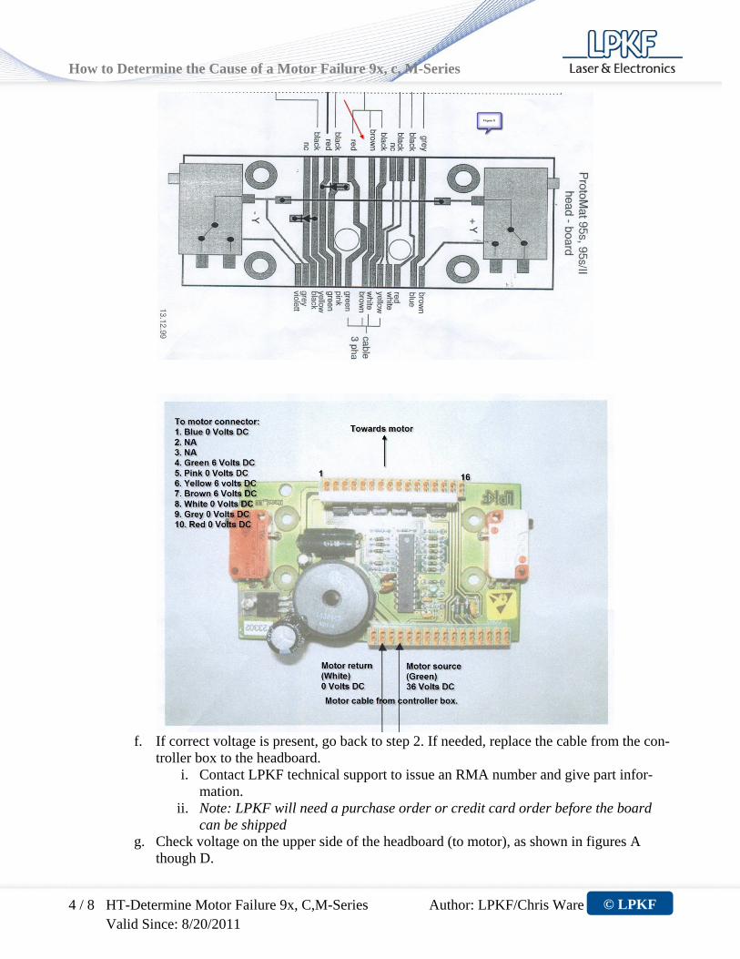
d. Move the top headboard out of the way. e. Check voltage on lower side of the headboard (motor is on the top of the picture)
i. For 91s and 92s, see figure A ii. For 95s and 95sII, see figure B
iii. For 93s, C and M series (except C30s EC and C40), see figure C iv. For C30s EC and C40, see figure D
How to Determine the Cause of a Motor Failure 9x, c, M-Series
4 / 8 HT-Determine Motor Failure 9x, C,M-Series Author: LPKF/Chris Ware Valid Since: 8/20/2011
© LPKF
f. If correct voltage is present, go back to step 2. If needed, replace the cable from the con-
troller box to the headboard. i. Contact LPKF technical support to issue an RMA number and give part infor-
mation. ii. Note: LPKF will need a purchase order or credit card order before the board
can be shipped g. Check voltage on the upper side of the headboard (to motor), as shown in figures A
though D.

How to Determine the Cause of a Motor Failure 9x, c, M-Series
5 / 8 HT-Determine Motor Failure 9x, C,M-Series Author: LPKF/Chris Ware Valid Since: 8/20/2011
© LPKF
h. If correct voltage is not present, replace the headboard. i. Contact LPKF technical support to issue an RMA number and give part infor-
mation. ii. Note: LPKF will need a purchase order or credit card order before the board
can be shipped i. Move the top headboard into position. j. Insert and tighten the nuts for the headboard extender posts. k. Replace the Y axis cover and tighten the four 3mm Allen screws. l. Troubleshooting complete.
6. Remove the controller box from the machine carriage.
a. Turn the motor off. b. Move the machine to the exchange position. c. Shut down power to the machine. d. Disconnect all cables from the controller box. If necessary, label the cables. e. Tilt the machine so that you can gain access to the bottom of the controller box.
i. The machine head will be towards the bottom and the connectors on the control-ler box will be facing you.
f. Unscrew the four (4) black feet g. With the 3mm or 4mm Allen wrench, remove the two (2) screws holding the controller
box to the machine carriage. h. Remove the controller box from the machine carriage. i. With a #3 phillips screwdriver, remove all screws from the controller box lid. j. Lift the lid off of the controller box. Caution: For machines with a 9’ x 12’ table size, the cables for the limit switch and ground-ing wire are mounted to the underside of the controller box lid.

How to Determine the Cause of a Motor Failure 9x, c, M-Series
6 / 8 HT-Determine Motor Failure 9x, C,M-Series Author: LPKF/Chris Ware Valid Since: 8/20/2011
© LPKF
7. Test motor fuse F703 a. With the voltmeter, conduct a resistance check on the fuse labeled F703.
b. Replace fuse if necessary c. Fuse specifications are:
i. 250 Volt, 5 Amp, Slow-blow (or time lag) d. If fuse is good, and testing at LPKF facility, go to step 8. e. If fuse is good, and testing at customers’ facility, go to step 9. f. If fuse is read as an open:
i. replace fuse ii. re-assemble controller box and attach to machine carriage
iii. re-connect all cables iv. turn machine on v. load a tool
vi. move machine head away from the exchange position vii. start the motor
viii. If the motor starts, troubleshooting complete ix. If the motor does not start, contact LPKF Tech Support for further troubleshoot-
ing at (503) 454-4229.
8. Test voltage from the SMCU to the DC or HF Amp board. (At LPKF facility only) Note: Does not apply for testing 20K and 30K DC motors.
a. Open controller box b. Hook controller box onto the test bench. c. Locate the green connector and cable that goes from the SMCU to the DC or HF ampli-
fier board.

How to Determine the Cause of a Motor Failure 9x, c, M-Series
7 / 8 HT-Determine Motor Failure 9x, C,M-Series Author: LPKF/Chris Ware Valid Since: 8/20/2011
© LPKF
d. With the voltmeter, check the voltage on the green connector on the SMCU.
i. The voltage readings going to the DC or HF amplifier board are as follows:
1. 20K, 30K and 40K motors: 76 volts DC on orange, 5 volts on red, no voltage on brown and black
2. 60K and 100K motor: 24 volts AC on orange, black and brown wires, 5 volts on red.
e. If correct voltage is not present, replace the SMCU board. i. Contact LPKF technical support for an RMA for a replacement SMCU.
f. If voltage is good, go to step 10.
9. Test Voltage from the SMCU to the DC or HF Amp board. (Customers or on-site repair by LPKF technician.)
a. Turn the controller box so that the cable connectors are facing the machine carriage. b. Connect all cables to the controller box. c. Turn the power to the machine on. d. Press the limit switch push buttons until the machine head stops. Verify that the green
power LED is lit. e. With a voltmeter, test the voltage from the SMCU to the DC or HF amplifier board.
Note: If troubleshooting a 20K motor, the voltage will go from the SMCU to the head cable, as described in step 4b.

How to Determine the Cause of a Motor Failure 9x, c, M-Series
8 / 8 HT-Determine Motor Failure 9x, C,M-Series Author: LPKF/Chris Ware Valid Since: 8/20/2011
© LPKF
f. The voltage readings should be as follows: i. 20K and 30K DC motor:
ii. 30K EC and 40K motor: iii. 60K and 100K motor:
g. If correct voltage is present, go to step 10. h. If correct voltage is not present, replace SMCU. Contact LPKF technical support to is-
sue an RMA number and give part information. Note: LPKF will need a purchase order or credit card order before the board can be shipped.
10. Test motor voltage output from the DC or HF Amplifier board a. With the volt meter, check the voltage from the amplifier board to the 5 pin circular
connector on the external wall of the controller box.
i. The voltage should be:
1. 30K and 40K DC motors: 36 volts DC on red wire only. 2. 60K/100K AC motors: 24 volts AC on red, brown and black wires. The
orange wire should be less than 5 volts. ii. If the correct voltage is not present, please contact LPKF technical support at
(503) 454-4229 or email at [email protected] to issue an RMA for a re-placement amplifier board and give part information.
Note: LPKF will need a purchase order or credit card order before the board can be shipped.