motor control and protection unit m10x user guide diagram functionality starter types protection...
TRANSCRIPT

Motor control and protection unitM10x user guide

2 Motor control and protection unit | M10x user guide M10x user guide | Motor control and protection unit 3
Table of contentsGeneralTarget groupUse of warning, caution, information and tip iconTerminologyRelated documentationRelated software versionDocument revision historyNew features available in enhanced products
Product overviewIntroductionStructure
Mounting
InterfacesTerminal designationsTypical diagram
FunctionalityStarter typesProtection functionsDigital inputsDigital outputsMaintenance functionMetering and monitoring
Communication interfaceOverviewMODBUS RTUPROFIBUS DP
ParameterizationOverviewParameterization via MD21/MD31Parameterization via MCUSetup softwareParameterization via FieldbusM10x Parameters
Accessories MD21/MD31 Operator panelParameterization Software
Appendix A: Technical data
44456667
888
10
111218
22224068747676
78787880
838383838383
8484
103
106
The information in this document is subject to change without notice and should not be construed as a commitment by ABB. ABB assumes no responsibility for any errors that may appear in this document.
In no event shall ABB be liable for direct, indirect, special, incidental, or consequential damages of any nature or kind arising from the use of this document, nor shall ABB be liable for incidental or consequential damages arising from use of any software or hardware described in this document.
This document and parts thereof must not be reproduced or copied without ABB’s written permission, and the contents thereof must not be imparted to a third party nor be used for any unauthorized purpose. The software described in this document is furnished under a license and may be used, copied, or disclosed only in accordance with the terms of such license.
All rights reserved.
Copyright © 2013 Xiamen ABB

4 Motor control and protection unit | M10x user guide M10x user guide | Motor control and protection unit 5
General
Target groupThe manual is primarily intended for those requiring information on the applications of M10x for the purpose of understanding, engineering, wiring and operating the product.
The objective of this manual is to provide the technical functions description of M10x.This manual should be studied carefully before installing, parameterizing or operating the motor control unit. It is assumed that the user has a basic knowledge of physical and electrical fundamentals, electrical wiring practices and electrical components.
This document should be used along with M10x Parameter Description, which provides detailed information about parameters and their applications.
Use of warning, caution, information and tip icon
TerminologyList of terms, acronyms, abbreviations and definitions used in the document:
Abbreviation Term Description
Alarm Alarm is defined as status transition from any state to abnormal state. Status transition to abnormal state can be data crossing over the pre-defined alarm limit.
DCS Distributed control system High level distributed control system
Local hardwiring A control access term describing that the M10x accepts its commands from the hardwired inputs, when the local control authority is enabled.
PCS Process control system High level process control system
MODBUS Fieldbus communication protocol
MODBUS RTU Fieldbus communication protocol
PROFIBUS-DP Fieldbus communication protocol with cyclic data transfer (V0).
PROFIBUS-DP/V1 Fieldbus communication protocol, extension of PROFIBUS-DP allowing acyclic data transfer and multi master (V1).
PTC Positive temperature coefficient PTC thermistors are semiconductor elements with a very high positive temperature coefficient.
RCU Remote control unit Local control unit with pushbutton and indicator to operate a device (eg, motor) from field level.
Remote fieldbus A control access term describing that the M10x accepts its commands from the fieldbus inputs, when the remote control authority is enabled.
RS485 Communication interface standard from EIA (Electronics Industries Association, USA), operating on voltages between 0V and +5V. RS-485 is more noise resistant than RS-232C, handles data transmission over longer distances, and can drive more receivers.
STP Shielded twisted pair A type of cable commonly used for signal transmission.
TOL Thermal overload protection Protection against overheating caused by overload
Trip A consequence of an alarm activated or an external trip command from another device to stop the motor or trip the circuit breaker.
MCC Motor control center Common term for a switchgear used for motor control and protection.
SOE Sequence of events A record of events with time stamp.
This publication includes Warning, Caution, and Information icons where appropriate to point out safety related or other important information. It also includes Tip icons to point out useful hints to the reader. The corresponding symbols should be interpreted as follows:
The electrical warning icon indicates the presence of a hazard that could result in electrical shock.
The warning icon indicates the presence of a hazard that could result in personal injury.
The caution icon indicates important information or warnings related to the concept discussed in the text. It might indicate the presence of hazard that could result on corruption of software or damage to equipment/property.
The information icon alerts the reader to pertinent facts and conditions.
The tip icon indicates advice on, for example, how to design your project or how to use a certain function
Although Warning notices are related to personal injury, and Caution notices are associated with equipment or property damage, it should be understood that the operation of damaged equipment could, under certain operational conditions, result in impaired process performance leading to personal injury or death. It is, therefore, imperative that you comply fully with all Warning and Caution notices.
6 Motor control and protection unit | M10x user guide M10x user guide | Motor control and protection unit 7
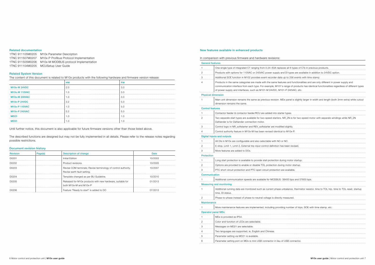
Related documentation1TNC 911105M0205 M10x Parameter Description 1TNC 911507M0207 M10x-P Profibus Protocol Implementation1TNC 911505M0206 M10x-M MODBUS protocol Implementation1TNC 911104M0205 MCUSetup User Guide
Related System VersionThe content of this document is related to M10x products with the following hardware and firmware version release:
HW FW
M10x-M 24VDC 2.0 3.0
M10x-M 110VAC 1.0 3.0
M10x-M 240VAC 1.0 3.0
M10x-P 24VDC 3.2 5.0
M10x-P 110VAC 1.0 5.0
M10x-P 240VAC 5.2 5.0
MD21 1.0 1.0
MD31 1.0 1.0
Until further notice, this document is also applicable for future firmware versions other than those listed above.
The described functions are designed but may not be fully implemented in all details. Please refer to the release notes regarding possible restrictions.
Document revision history
Revision Page(s) Description of change Date
D0201 Initial Edition 10/2003
D0202 Product revisions 10/2005
D0203 Revise COM terminals; Revise terminology of control authority. Revise earth fault setting.
10/2007
D0204 Template changed as per BU Guideline. 10/2010
D0205 Released for M10x products with new hardware, suitable for both M10x-M and M10x-P
01/2013
D0206 Feature "Ready to start" is added to DO 07/2013
New features available in enhanced products
In comparison with previous firmware and hardware revisions:
General features
1 One single type of integrated CT ranging from 0.24~63A replaces all 6 types of CTs in previous products.
2 Products with options for 110VAC or 240VAC power supply and DI types are available in addition to 24VDC option.
3 Additional SOE function in M102 provides event recorder data up to 256 events with time stamp.
4 Products in the same categories are made with the same features and functionalities and are only different in power supply and communication interface from each type. For example, M101's range of products has identical functionalities regardless of different types of power supply and interfaces, such as M101-M 24VDC, M101-P 240VAC, etc.
Physical dimension
1 Main unit dimension remains the same as previous revision. MDx panel is slightly larger in width and length (both 3mm extra) while cutout dimension remains the same.
Control features
1 Contactor feeder & contactor feeder/RCU are added into starter types.
2 Two separate start types are available for two-speed starters. NR_2N is for two-speed motor with separate windings while NR_2N Dahlander is for Dahlander connection motor.
3 Control logic in NR_softstarter and REV_softstarter are modified slightly.
4 Control authority feature in M10x-M has been revised identical to M10x-P.
Digital inputs and outputs
1 All DIs in M10x are configurable and also selectable with NO or NC.
2 E-stop, Limit 1, Limit 2, External trip input control definition has been revised.
3 More features are added to DOs.
Protection
1 Long start protection is available to provide stall protection during motor startup.
2 Options are provided to enable or disable TOL protection during motor startup.
3 PTC short circuit protection and PTC open circuit protection are available.
Communication
1 Additional communication speeds are available for MODBUS: 38400 bps and 57600 bps.
Measuring and monitoring
1 Additional running data are monitored such as current phase unbalance, thermistor resistor, time to TOL trip, time to TOL reset, startup time, DI status.
2 Phase-to-phase instead of phase-to-neutral voltage is directly measured.
Maintenance
1 More maintenance features are implemented, including providing number of trips, SOE with time stamp, etc.
Operator panel MDx
1 MDx is provided as IP54.
2 Color and function of LEDs are selectable.
3 Messages on MD21 are selectable.
4 Two languages are supported, ie, English and Chinese.
5 Parameter setting via MD21 is available.
6 Parameter setting port on MDx is mini USB connector in lieu of USB connector.

8 Motor control and protection unit | M10x user guide M10x user guide | Motor control and protection unit 9
Introduction M10x is an intelligent motor control and protection device based on current measurement or current measurement and voltage measurement. Installed in and supplied as part of ABB Low Voltage switchgear MNS®, it is part of a low voltage system family of products that provides customers with an ABB intelligent system solution.
M10x is a microprocessor-based product providing comprehensive but standard features in one device. Standard features simplify maintenance and plant expansion. Each motor starter is equipped with one standard M10x device. With dedicated parameters in each device, M10x provides specific control, monitoring and protection functions, tailored for various motor applications.
Coupled with the world's most common industrial fieldbus interfaces (PROFIBUS DP and MODBUS), M10x integrates smoothly and efficiently into industrial control and plant management systems. Every individual M10x device can be accessed and interrogated to determine both actual and operating parameters. Fast response time for alarm or trip status makes real time control of a complete process possible. Statistical recording of running hours and number of operations assists with predictive maintenance scheduling.
For AC motor and the operated installations this means: Reliable protection Maximum utilization Continuous supervision Flexibility
Product overview
StructureM10x has two parts: Main unit (with current converter unit) Operator panel MD21/MD31
Main unitThe main unit is constructed with two parts: the electronics of the motor control unit and the integrated CT. Main unit is a one type device with the integrated CT range starting from 0.24 to 63A. For motor ratings larger than 63A, interposing CTs can be selected. Main unit is designed with a mounting rail fixed to the bottom of the device for easy vertical DIN rail mounting. Screws and other mounting accessories also provide for vertical and horizontal screw mounting.
Operator panel MD21/MD31The operator panel is the user interface mounted on the front door or drawer. With control buttons, LED, LCD module (MD21 only), MD21/MD31 provides functions for motor control, supervision and parameterizing. One operator panel is provided for each main unit upon request.
M10x materialThe enclosure of the M10x is made of polycarbonate. Flammability rating of the material is UL 94 V-0 and material is halogen free.
Color of the enclosure is RAL 7012.
For a detailed description of MD21/MD31, refer to the chapter: Accessories.
Fig. 1. M10x and MD21

10 Motor control and protection unit | M10x user guide M10x user guide | Motor control and protection unit 11
Basic dimension of M10xW x H x D=110mm x 140mm x 75mm
Typical installation of M10xVertical DIN rail or vertical screw mounting on horizontal plate
Basic dimension of MD21W x H x D=91mm x 75mm x 24.3mm
Mounting dimension of MD21W x H=84mm x 68mm
Basic dimension of MD31W x H x D=88mm x 50mm x 24.3mm
Mounting dimension of MD31W x H=84mm x 46mm
For installation details of M10x and MDx, see the related documentation installation manual.
Terminal blocks of M10x are located on the top of the main unit for easy access. There are 3 sets of I/O terminal blocks and 1 set of RJ11 connectors as shown.
Fig. 3-1. Top view terminal layout (24VDC)
Picture 3-2. Top view terminals layout (110VAC or 240VAC)
Fig. 2. M10x in 8E/4 module
Mounting of M10x Interfaces

12 Motor control and protection unit | M10x user guide M10x user guide | Motor control and protection unit 13
Terminal designations
Terminal block Terminal numberDesignation… plug/contacts
Remarks
X1
24VDC typeX1:1…X1:14 Digital input Cross section
1.5mm2X1:15…X1:16 PTC input
110/240VAC typeX1:1…X1:10 Digital input Cross section
2.5mm2X1:11…X1:12 PTC input
X2 X2:1…6 Interface for MDxCable with RJ11 connector provided
X3
X3:1…5Fieldbus for external communication Cross section
2.5mm2X3:6,7 RCT input
X3:8…13 Voltage input
X4
X4:1…9 Relay outputCross section 2.5mm2
X4:10,11 Power supply
X4:12 Ground
L1-T1;L2-T2;L3-T3 Lead-throughCurrent measurement
Φ10mm Window
Table 1. Device terminals
Power supplyDepending on the product type, three types of power supply are available, ie, 24VDC, 110VAC and 240VAC. Power supply of the device should be always derived from an uninterrupted and reliable supply source.
Terminal no. Name Description
X4:11 24VDC or L 24VDC +, 110VAC or 240VAC
X4:10 GND or N 0VDC or NeutralTable 2. Power supply input terminals
Digital inputM10x 24VDC type has 13 Dls and M10x 110/240VAC type has 9 DIs. Digital inputs are cyclically read. Functions of all digital inputs are selectable, and can be assigned to a defined function.
M10x reads the status of input contacts by measuring the voltage drop on inputs:
Terminal no. Name Description
X1:1 DI0 Digital input 0
X1:2 DI1 Digital input 1
X1:3 DI2 Digital input 2
X1:4 DI3 Digital input 3
X1:5 DI4 Digital input 4
X1:6 DI5 Digital input 5
X1:7 DI6 Digital input 6
X1:8 DI7 Digital input 7
X1:9 DI8 Digital input 8
X1:10 DI9 Digital input 9
X1:11 DI10 Digital input 10
X1:12 DI11 Digital input 11
X1:13 DI12 Digital input 12
X1:14 DI_COM Digital input common terminalTable 3. Digital inputs with 24VDC supply
Terminal no. Name Description
X1:1 DI0 Digital input 0
X1:2 DI1 Digital input 1
X1:3 DI2 Digital input 2
X1:4 DI3 Digital input 3
X1:5 DI4 Digital input 4
X1:6 DI5 Digital input 5
X1:7 DI6 Digital input 6
X1:8 DI7 Digital input 7
X1:9 DI8 Digital input 8
X1:10 DI_COM Digital input common terminalTable 4. Digital inputs with 110/240VAC supply
i ) For 24VDC, it is recommended to use separate supply source for power supply and digital inputs, especially in the case that DI signals are taken from the field which is located a long distance from MCCs.

14 Motor control and protection unit | M10x user guide M10x user guide | Motor control and protection unit 15
Fig. 4. Illustration of DIs wiring to M10x
PTC input (M102 only)PTC function is only available in M102 series of products. Type A temperature sensor with a characteristic curve according to IEC 60947-8 to follow the temperature of motor winding is used in the device. PTC connector is located on the top of M102 unit, terminal X1.
i) M101 series of products do NOT have PTC function built in. ii) It is recommended to short terminal X1:15 and X1:16 together to avoid
potential external disturbance when this function is not activated.
iii) STP cable is recommended for PTC circuit connections.
Terminal no. Name Description
X1:15 PTCA PTC measurement input A
X1:16 PTCB PTC measurement input BTable 5-1. PTC input terminals (24VDC type)
Terminal no. Name Description
X1:11 PTCA PTC measurement input A
X1:12 PTCB PTC measurement input BTable 5-2. PTC input terminals (110/240VAC type)
Fieldbus interfaceSelected by different product types, M10x can be used directly on MODBUS RTU or PROFIBUS DP networks. Both types of product are based on physical RS485 layer. Dual RS485 interfaces are provided in MODBUS type of device to support full redundancy network design.
Terminal no. Name Description
X3:1 2B Serial RS485 B
X3:2 2A Serial RS485 A
X3:3 SHIELD 485 shield
X3:4 1B Serial RS485 B
X3:5 1A Serial RS485 ATable 6. MODBUS dual RS485 interfaces
Terminal no. Name Description
X3:1 5V Power supply 5V+ for bus terminator
X3:2 B RS485 B
X3:3 A RS485 A
X3:4 GND Power supply GND for bus terminator
X3:5 SHIELD ShieldTable 7. PROFIBUS RS485 interface
Residual current transformerM10x supports earth fault protection through external residual current transformer (RCT).
Terminal no. Name Description
X3:6 Ioa Residual current transformer input A
X3:7 Iob Residual current transformer input B
Table 8. Residual current transformer terminals
i) Different sizes or types of RCT are available. Refer to M10x ordering guide for details.ii) It is recommended to short terminals X3:6 and X3:7 to avoid potential external disturbance when RCT is not in use.iii) It is recommended to use STP cable for RCT circuit connections.

16 Motor control and protection unit | M10x user guide M10x user guide | Motor control and protection unit 17
Voltage measurement (M102 only)Voltage measurement and protections are available in M102 range of products.
Voltage unit is available in M102 only.
Terminal no. Name Description
X3:9 VL3 Phase L3 voltage input
X3:11 VL2 Phase L2 voltage input
X3:13 VL1 Phase L1 voltage inputTable 9. Voltage input terminals
i) When single phase system is selected, voltage measurement is based on phase L1 - phase L3. Connect L to VL1(X3:13) and neutral to VL3(X3:9).
Current measurement terminalM10x continuously measures three motor phase currents. The phase current data will be used by the protection functions and is reported to the fieldbus. Phase currents are reported as a value relative to the motor nominal current In.
Current wires are fed through current sensors from either side of the terminal.
Direction can be either L->T or T->L considering that all currents must have the same direction.
Motor nominal currents above 63A are not measured directly, but instead intermediate current transformer’s secondary side is connected through M10x current measurement terminal.
i) When single phase system is selected, current measurement is based on phase L1.ii) The measurement range of internal CT is from 0.08A to 63A.
Contactor control outputM10x supports various motor starter types. The control of the contactor by M10x is via internal output relays (CCA, CCB, CCC relays) by the microprocessor.
Internal relays CCA and CCB are hardwire-interlocked to prevent both contactors being closed at the same time.
1) M101 is equipped with CCA and CCB output relays only.2) For external connecting contactors, spark suppression is necessary for all types of contactors except the AF types to maintain
reasonable service life of relays.
Terminal no. Name Description M101 M102
X4:6 CCLI Contactor control voltage input
X4:7 CCA Contactor control A
X4:8 CCB Contactor control B
X4:9 CCC Contactor control C
Table 10. Contactor control terminals
Digital outputM10x is also equipped with two sets of auxiliary programmable digital output relays which function according to project specific settings.
Terminal no. Name Description M101 M102
X4:1 GR1_A
Contactor control voltage input X4:2 GR1_B
X4:3 GR1_C
X4:4 GR2_A Programmable relay output 2 (NO)
X4:5 GR2_B
Table 11. Digital output terminals
The output status of programmable relays may change in response to different assigned functions.
1) M101 is equipped with only one set of output relay (GR1).
2) For external connecting contactors, spark suppression is necessary for all types of contactors except the AF types to maintain reasonable service life of relays.
Interface for MD21/MD31M10x is connected with operator panel MD21/MD31 using RJ11 interface.
Ground terminal
Terminal no. Name Description
X4:12 GROUND Ground safety and surgeTable 12. Ground terminal
This is an additional ground terminal provided for dissipating transient signals and surges. It must be connected by a thick wire or braid to the system ground for reliable operation.

18 Motor control and protection unit | M10x user guide M10x user guide | Motor control and protection unit 19
Typical diagram
Typical wiring diagrams of different types of M10x are shown in this section.
M101 24VDC
Fig. 6-1. Typical wiring diagram for M101 (24VDC type)
Note 1) Block A shows MODBUS dual RS485 interface. For PROFIBUS interface, Block B below should replace Block A.
Shield and Ground (X4:12) are connected internal of M10x.
Digital output contacts (GR1_A, GR1_B &GR1_C) as shown are floating NC and NO contacts from the same relay and respond to parameter settings.
Eg. when ‘Trip’ is set to digital output, NO contact will close under healthy conditions. In the case of power loss, contact status will restore as shown.
M101 110VAC or 240VAC
Fig. 6-2. Typical wiring diagram for M101 (110/240VAC type)
Note 1) Block A shows MODBUS dual RS485 interface. For PROFIBUS interface, Block B below should replace Block A.
Shield and Ground (X4:12) are connected inside M10x.
Digital output contacts (GR1_A, GR1_B &GR1_C) as shown are floating NC and NO contacts from the same relay and respond to parameter settings, eg, when Trip is set to digital output, NO contact will close under healthy conditions.In the case of power loss, contact status will restore as shown.
Block B
*Note 1)
Block B
*Note 1)
Block A
*Note 1)
Block A
*Note 1) Redundant Port
Redundant Port

20 Motor control and protection unit | M10x user guide M10x user guide | Motor control and protection unit 21
M102 24VDC
Fig. 7-1. Typical wiring diagram for M102 (24VDC type)
Note 1) Block A shows MODBUS dual RS485 interface. For PROFIBUS interface, Block B below should replace Block A.
Shield and Ground (X4:12) are connected internal of M10x.
Digital output contacts (GR1_A, GR1_B &GR1_C) as shown are floating NC and NO contacts from the same relay and respond to parameter settings, eg, when Trip is set to digital output, NO contact will close under healthy conditions. In the case of power loss, contact status will restore as shown.
M102 110VAC or 240VAC
Fig. 7-2. Typical wiring diagram for M102 (110/240VAC type)
Note 1) Block A shows MODBUS dual RS485 interface. For PROFIBUS interface, Block B below should replace Block A.
Shield and Ground (X4:12) are connected inside M10x.
Digital output contacts (GR1_A, GR1_B &GR1_C) as shown are floating NC and NO contacts from the same relay and respond to parameter settings, eg, when Trip is set to digital output, N/O contact will close under healthy conditions. In the case of power loss, contact status will restore as shown.
Block B
*Note 1)
Block B
*Note 1)
Block A
*Note 1)
Block A
*Note 1)
Redundant Port Redundant Port

22 Motor control and protection unit | M10x user guide M10x user guide | Motor control and protection unit 23
Starter typesM10x offers various kinds of motor starting control modes via the control of relay output. It supervises the operating state of the contactor according to the feedback of auxiliary contact, predefined feedback timeout and current.
The following starting control modes are offered:
Starter type M101 M102
NR-DOL
REV-DOL
NR-DOL/RCU
REV-DOL/RCU
Actuator
NR-S/D
NR-2N
NR-2N Dahlander
Autotransformer
NR_softstarter
REV_softstarter
Contactor feeder
Contactor feeder/RCU
Feeder
Table 13. Starter types supported by M10x
NR_DOL: non reversing direct online REV_DOL: reversing direct online NR_DOL/RCU: non reversing direct online with RCU REV_DOL/RCU: reversing direct online with RCU Actuator: actuator with limit switch input NR_S/D: non reversing star-delta NR_2N: two-speed driver for non reversing starter with separate winding NR_2N Dahlander: two-speed driver for Dahlander connection Autotransformer: autotransformer starter NR_softstarter: non reversing softstarter control REV_softstarter: reversing softstarter control Contactor feeder: contactor controlled feeder Contactor feeder/RCU: contactor controlled feeder with RCU Feeder: feeder is regarded as a specific starter mode in M10x
Starter type is selected with a dedicated parameter to match the wiring for contactor and motor control circuits.
i) PIN numbers assigned for DIs in below starters are shown as per default settings and and are subject to change to meet engineering requirements.
ii) Spark suppression is necessary for all types of connecting contactors except AF types through M10x output relays to maintain reasonable service life of the output relays. Interface relays should also be considered in engineering to increase reasonable service life. Interface relay is recommended to be used for contactor type A75 and above.
Fig. 8. Surge suppressors on contactor coils
Precautions must be taken in system designs to avoid potential high electromagnetic disturbance which may result in unstable network and malfunction of M10x relays. For example, in applications that variable speed drives are used in a large scale, harmonic filter devices are required in system design to reduce impact to the network.
Functionality

24 Motor control and protection unit | M10x user guide M10x user guide | Motor control and protection unit 25
NR-DOL STARTERNR_DOL starter is a basic starter type for driving motor in one direction. When start command has been received from field or local I/O, the contactor control output will be energized and remains in this in condition until stop command has been received or any protection function is activated.
Name Pin Description
CCLI X4:6 Contactor control voltage input
CCA X4:7 Contactor control A
DI6(F_Ca) X1:7 Contactor control A feedback
DI5(Loc/R) X1:6 Local/remote control switch inputTable 14. NR-DOL starter contactor control interface (for M10x)
The definition of the terminal X1 in the above list is only an example.
Fig. 9. Control circuit for NR-DOL starter (for M10x)
NR-DOL/RCU STARTERRemote control unit (RCU) is a starter type where contactors are directly controlled by a special RCU switch located near the motor. This allows control of the motor even without the M10x.
Name Pin Description Remarks
CCLI X4:6 Contactor control voltage input
CCA X4:7 Contactor control A
GR1_C X4:3 Programmable relay output Only for M101
CCC X4:9 Contactor control C Only for M102
DI6(F_Ca) X1:7 Contactor control A feedback
DI5(Loc/R) X1:6 Local/remote control switch inputTable 15. NR-DOL/RCU starter contactor control interface (for M10x)
The definition of the terminal X1 in the above list is only an example.
Fig. 10-1. Control circuit for NR-DOL/RCU starter (for M101)
Fig. 10-2 Control circuit for NR-DOL/RCU starter (for M102)

26 Motor control and protection unit | M10x user guide M10x user guide | Motor control and protection unit 27
REV-DOL STARTERREV-DOL uses contactor control output A to control the contactor that drives the motor in direction CW. Correspondingly, contactor control output B is used for direction CCW. When the starting motor to either direction contactor will be energized and is stopped (not energized) by command from fieldbus or local I/O, or active protection function.
Name Pin Description
CCLI X4:6 Contactor control voltage input
CCA X4:7 Contactor control A
CCB X4:8 Contactor control B
DI6(F_Ca) X1:7 Contactor control A feedback
DI7(F_Cb) X1:8 Contactor control B feedback
DI5(Loc/R) X1:6 Local/remote control switch inputTable 16. REV-DOL starter contactor control interface (for M10x)
The definition of the terminal X1 in the above list is only an example.
Fig. 11. Control circuit for REV-DOL starter (for M10x)
REV-DOL/RCU starterThe functionality of this starter type is the same as the to NR-DOL/RCU starter with support for reversing use of motor.
Name Pin Description Remarks
CCLI X4:6 Contactor control voltage input
CCA X4:7 Contactor control A
CCB X4:8 Contactor control B
GR1_C X4:3 Programmable relay output1 Only for M101
CCC X4:9 Contactor control C Only for M102
DI6(F_Ca) X1:7 Contactor control A feedback
DI7(F_Cb) X1:8 Contactor control B feedback
DI5(Loc/R) X1:6 Local/remote control switch inputTable 17. REV-DOL starter contactor control interface (for M10x)
The definition of the terminal X1 in the above list is only an example.
Fig. 12. Control circuit for REV-DOL/RCU starter (for M101)
Fig. 13. Control circuit for REV-DOL/RCU starter (for M102)

28 Motor control and protection unit | M10x user guide M10x user guide | Motor control and protection unit 29
Actuator starter (M102 only)This starter type is for controlling valves and actuators by using limit switches
Name Pin Description
CCLI X4:6 Contactor control voltage input
CCA X4:7 Contactor control A
CCB X4:8 Contactor control B
CCC X4:9 Contactor control C
DI0 (Limit1) X1:1 Limit position switch 1 input
DI1 (Limit2) X1:2 Limit position switch 2 input
DI9 (Torque) X1:10 Torque switch input
DI6 (F_Ca) X1:7 Contactor control A feedback
DI7 (F_Cb) X1:8 Contactor control B feedback
DI5 (Loc/R) X1:6 Local/remote control switch inputTable 18. Actuator starter contactor control interface
The definition of the terminal X1 in the above list is only an example.
Fig. 14. Control circuit for actuator starter
Limit switch stops the motor when activated. Additionally, the start command is only allowed to reverse direction. Torque switch is selectable by parameterization.
NR-S/D starter (M102 only)Motor start current is reduced in star connection to 1/3 of the current in delta connection, with lower torque during the same time.
Start-to-delta starting sequence is based on the presented control logic (Figure 15). The changeover condition is time.
The following guideline is applied for selecting parameter values:
Changeover time < Motor startup time
Name Pin Description
CCLI X4:6 Contactor control voltage input
CCA X4:7 Contactor control A
CCB X4:8 Contactor control B
CCC X4:9 Contactor control C
DI5 (Loc/R) X1:6 Local/remote control switch input
DI6 (F_Ca) X1:7 Contactor control A feedback
DI7 (F_Cb) X1:8 Contactor control B feedback
DI8 (F_Cc) X1:9 Contactor control C feedback Table 19. NR_S/D starter contactor control interface
The definition of the terminal X1 in the above list is only an example.
Fig. 15. Control circuit for NR-S/D starter

30 Motor control and protection unit | M10x user guide M10x user guide | Motor control and protection unit 31
NR-2N starter (M102 Only)NR-2N uses two contactors to control motor rotation speed; the motor contains separate windings. Rotation speed can be changed “on the fly” without stop command in between. Low speed (start 1) can be changed to high speed (start 2) immediately, and high speed can be changed to low speed after a changeover time.
Current measurement for NR-2N uses two external current transformers measuring current from motor main supply. External current transformers can be selected separately for both speeds.
The following guideline is applied for selecting parameter values:
Changeover time < Motor startup time
Name Pin Description
CCLI X4:6 Contactor control voltage input
CCA X4:7 Contactor control A
CCB X4:8 Contactor control B
DI6 (F_Ca) X1:7 Contactor control A feedback
DI7 (F_Cb) X1:8 Contactor control B feedback
DI5 (Loc/R) X1:6 Local/remote control switch inputTable 20. NR-2N starter contactor control interface
The definition of the terminal X1 in the above list is only an example.
Fig. 16 Control circuit for NR_2N starter, separate windings
Operating sequence in NR-2N Sending command Start1 (low speed N1) to close contactor CCA Sending command Start2 (high speed N2) to close contactor CCB Contactors are latched Stop command opens CCA or CCB
Motor can be controlled with sequences: Stop -> Start1 -> Stop Stop -> Start2 -> Stop Stop -> Start1 -> Start2 ->Stop Stop -> Start2 -> Changeover delay-> Start1 -> Stop
NR-2N Dahlander STARTER (M102 Only)NR-2N Dahlander uses three contactors to control motor rotation speed where motor is equipped with a three-phase winding. Rotation speed can be changed “on the fly” without stop command in between. Low speed (start 1) can be changed to high speed (start 2) immediately, and high speed can be changed to low speed after a changeover time.
Current measurement for NR-2N Dahlander uses two external current transformers measuring current from motor main supply. External current transformers can be selected separately for both speeds.
The following guideline is applied for selecting parameter values:Changeover time < Motor startup time
Name Pin Description
CCLI X4:6 Contactor control voltage input
CCA X4:7 Contactor control A
CCB X4:8 Contactor control B
CCC X4:9 Contactor control C
DI5 (Loc/R) X1:6 Local/remote control switch input
DI6 (F_Ca) X1:7 Contactor control A feedback
DI7 (F_Cb) X1:8 Contactor control B feedback
DI8 (F_Cc) X1:9 Contactor control C feedback Table 21. NR-2N Dahlander starter contactor control interface
The definition of the terminal X1 in the above list is only an example.

32 Motor control and protection unit | M10x user guide M10x user guide | Motor control and protection unit 33
Fig. 17. Control circuit for NR_2N Dahlander starter
Operating sequence in NR-2N Dahlander Sending command Speed1 to close contactor CCA Sending command Speed2 to close contactor CCB and CCC Contactors are latched Sending stop command to open CCA or CCB + CCC
Motor can be controlled with sequences: Stop -> Start1 -> Stop Stop -> Start2 -> Stop Stop -> Start1 -> Start2 ->Stop Stop -> Start2 -> Chang over delay-> Start1 -> Stop
Autotransformer starter (M102 only)This starter type is used to control the autotransformer unit in order to minimize voltage drop during motor startup. Autotransformer starter with three contactors supports motor starting with reduced voltage, thus providing reduced motor startup current. The starting torque will be reduced accordingly,
The following guideline applies for selecting parameter values:Changeover time < Motor startup time
Name Pin Description
CCLI X4:6 Contactor control voltage input
CCA X4:7 Contactor control A
CCB X4:8 Contactor control B
CCC X4:9 Contactor control C
DI5 (Loc/R) X1:6 Local/remote control switch input
DI6 (F_Ca) X1:7 Contactor control A feedback
DI7 (F_Cb) X1:8 Contactor control B feedback
DI8 (F_Cc) X1:9 Contactor control C feedback Table 22. Autotransformer starter contactor control interface
The definition of the terminal X1 in the above list is only an example.
Fig. 18. Control circuit for autotransformer starter

34 Motor control and protection unit | M10x user guide M10x user guide | Motor control and protection unit 35
NR-softstarter (M102 only)Softstarter applications are for controlling the motor accessory softstarter device. M102 gives start and stop commands to the softstarter unit. The softstarter is set for adjusting motor voltage with its own parameters. More information about softstarter can be found in the softstarter manual.
This starter type supports all protection functions during normal running situations. For motor start and stop period, some of the protection functions are disabled by these parameters.
Name Pin Description
CCLI X4:6 Contactor control voltage input
CCA X4:7 Contactor control A
CCC X4:9 Contactor control C
DI6 (F_Ca) X1:7 Contactor control A feedback
DI5 (Loc/R) X1:6 Local/remote control switch input Table 23. NR_softstarter starter contactor control interface
The definition of the terminal X1 in the above list is only an example.
Fig. 19. Control circuit for NR-softstarter
Operating sequence for NR-softstarter Start1 to close CCA followed by CCC Stop to open CCC followed by CCA after ramp down time delay.
REV-softstarter (M102 Only)This starter is of similar functionality as the NR-softstarter starter, with additional function to support reversing the motor.
Name Pin Description
CCLI X4:6 Contactor control voltage input
CCA X4:7 Contactor control A
CCB X4:8 Contactor control B
CCC X4:9 Contactor control C
DI5 (Loc/R) X1:6 Local/Remote control switch input
DI6 (F_Ca) X1:7 Contactor control A feedback
DI7 (F_Cb) X1:8 Contactor control B feedback Table 24. REV-softstarter starter contactor control interface
The definition of the terminal X1 in the above list is only an example.
Fig. 20. Control circuit for REV-softstarter
Operating sequence for REV-softstarter Start1 to close CCA followed by CCC Start2 to close CCB followed by CCC Stop to open CCC followed by CCA or CCB after ramp down time delay.

36 Motor control and protection unit | M10x user guide M10x user guide | Motor control and protection unit 37
Contactor feederContactor feeder is regarded in M10x as a specific starter type to provide measurement, control and protection functionality to a contactor feeder circuit. When start command has been received from field or local I/O, the contactor control output will be energized and remains in this condition until stop command has been received or any protection function is activated.
Name Pin Description
CCLI X4:6 Contactor control voltage input
CCA X4:7 Contactor control A
DI6(F_Ca) X1:5 Contactor control A feedback
DI5(Loc/R) X1:6 Local/remote control switch inputTable 25. Contactor feeder contactor control interface
(i) The definition of the terminal X1 in the above list is only an example.
(ii) Power, energy and other parameters related to Power factor are NOTcorrect and should not be referred to.
Fig. 22. Control circuit for contactor feeder
Contactor feeder/RCURemote control unit (RCU) is a starter type where contacters are directly controlled by a special RCU switch located near the motor. This allows control of the motor even without the M10x.
Name Pin Description Remark
CCLI X4:6 Contactor control voltage input
CCA X4:7 Contactor control A
GR1_C X4:3 Programmable relay output Only for M101
CCC X4:9 Contactor control C Only for M102
DI6(F_Ca) X1:7 Contactor control A feedback
DI5(Loc/R) X1:6 Local/remote control switch inputTable 26. Contactor feeder/RCU contactor control interface (for M10x)
i) The definition of the terminal X1 in the above list is only an example.ii) Power, energy and other parameters related to power factor are NOT correct and should not be referred to.
Fig. 23-1. Control circuit for contactor feeder/RCU (for M101)
Fig. 23-2. Control circuit for contactor feeder/RCU (for M102)

38 Motor control and protection unit | M10x user guide M10x user guide | Motor control and protection unit 39
FeederFeeder mode is regarded in M10x as a specific starter type to provide measurement and control functionality. The protection of feeder is not covered in M10x and is normally done by main circuit breaker. The feeder mode in M10x is designed to provide a complete intelligent solution in MCC plants where the feeder circuits are usually small, but important parts from the MCC plant management point of view.
Name Pin Description
CCLI X4:6 Contactor control voltage input
CCA X4:7 Control YC /motor drive in MCCB (2 seconds holding)
CCB X4:8 Control YO/motor drive in MCCB (2 seconds holding)
DI6 (F_Ca) X1:7 Circuit breaker position aux. feedback
DI9 (External trip input) X1:10 Circuit breaker trip aux. feedback
DI5 (Loc/R) X1:6 Local/remote control switch input* Table 27. Feeder control interface
i) The definition of the terminal X1 in the above list is only an example.ii) Power, energy and other parameters related to power factor are NOTcorrect and should not be referred to.
Fig. 21. Control circuit for feeder
Feeder application in M10x is confined to certain features. End users need to be informed on these confines when feeder application is required through M10x.
Operating:
Start1 command activates contactor output relay CCA for 2 seconds.
Stop command activates contactor output relay CCB for 2 seconds and clear fault annunciation after fault is cleared.
External trip occurs a trip message and will be reset when the signal is inactive.
Monitoring:
Circuit breaker close/open status
Circuit breaker trip
Protection:
Motor protection functions are not suitable for feeder application. All protections except earth fault protection in M10x are automatically disabled during parameter setting when feeder type is selected.
Measuring:
Current, voltage are measured by M10x. Power, energy and other parameters related to power factor are NOT correct and should not be referred to.

40 Motor control and protection unit | M10x user guide M10x user guide | Motor control and protection unit 41
Protection functionsThe module provides full protection for motors by supervising three voltage phases, three current phases, earth fault current, PTC sensor, startup time, the state of contactors and the state of the main switch.
Response of protection functions is based on the parameters given by the user. The operation of separate functions is independent, thus protection functions can be active at the same time but the one which indicates the situation first will give a trip for the motor.
According to the application, all kinds of protection can be enabled, disabled by the upper level system or MCU setup tool, and the protection characteristics can be adjusted. Protection module offers the following protection and supervisory functions:
Protection type M101 M102
Overload protection
Stall protection
Long start protection
Phase failure protection
Unbalance protection
Underload protection
Noload protection
Earth fault protection
PTC protection
Undervoltage protection
Start limitation protection
Table 28. Protection functions in M10x
Overload protection Thermal overload protection (TOL) protects the motor against overheating.The motor thermal condition is simulated by a calculation. The result of the calculation is stored in a thermal register and can be reported via operator panel or fieldbus interface. Calculation is accomplished in a different motor operation conditions, principly presented below. Thermal increase and decrease are simulated by TOL protection function for running and stopped motor.
Fig. 24. Principle picture of motor thermal simulation
M10x simulates thermal conditions in the motor for all operating modes (running or stopped). This permits maximum utilization of an installation and assures safe protection of the motor. Thermal overload protection simulation accounts for the temperature rise of both the stator winding and the iron mass of the motor. It gives thorough consideration of the effect of motor overheating due to three-phase unbalance during the simulation calculation of motor thermal overload.

42 Motor control and protection unit | M10x user guide M10x user guide | Motor control and protection unit 43
There are two thermal models supported by M10x: standard or EEx e. The standard model makes use of parameters trip class, t6 in thermal overload calculation. The protection of explosion proof three-phase motors with type of protection ‘increased safety’ EEx e is done with two special parameters, the Ia/In ratio (stall/nominal current ratio) and Te time.
The following diagram offers the characteristic curve of overload protection, in which the characteristics are adjusted by changing t6 (trip time for current IL max=6xIn from the cold state).
Fig. 25. Trip curve from cold condition
The maximum thermal capacity level is 100%. Maximum level is reached when the motor has been running with a current 6xIn at the time t6 starting from the cold state in ambient temperature 40°C.
Trip class T6
10A 3-7
10 7-12
20 10-25
30 15-38Table 29. IEC 60947-4-1 trip class when ambient temperature 40°C, balanced motor current
In some applications, it is beneficial to be able to bypass the TOL protection momentarily because of the process reasons. The lifetime of the motor will be shortened, but it might the more costly to stop the process. TOL bypass is a special command given through the fieldbus. There is a dedicated parameter to enable the execution of this command. TOL bypass function is available only for TOL standard model, thus it cannot be enabled if TOL EEx e model is in use.
When thermal level is above parameterized alarm level, it is possible to to send a bypass command to M10x via fieldbus. When bypass function is activated, the thermal image is allowed to rise to 200% level before a trip will occur. If the thermal level decreases below alarm level before a trip occurs, bypass function will be automatically clear. New command has to be sent to reactivate it after alarm level is crossed.
If motor is in overload condition, i.e. ILmax > 1.14 x TFLC (thermal full load current multiplier reduced by motor ambient temperature), the overload alarm is activated to indicate overload. If motor is stopped before trip and the thermal capacity decreases below TOL alarm level, the bypass functionality is disabled. Bypass command is ignored when running under alarm level.
Function
Setting range 0=Disabled 1=Enabled 2=Disabled during motor startup
Default value Enabled
Step value 1
Disabled during motor startup
Setting range 0=Enabled during motor startup1=Disabled during motor startup
Default value 0
Step value 1
Trip reset mode
Setting range 1=Auto 2=Local 3=Remote 4=Remote and local
Default value 4
Step value 1
Thermal model
Setting range 0=Standard model 1=EEX e
Default value 0
Step value 1

44 Motor control and protection unit | M10x user guide M10x user guide | Motor control and protection unit 45
TOL bypass
Setting range 0=Disabled 1=Enabled
Default value Disabled
T6
Setting range 3-40sec
Default value 6sec
Step value 1
Cool coefficient
Setting range 1-10
Default value 4
Step value 1
Ia/In
Setting range 1.2-8.0
Default value 5.0
Step value 0.1
Te
Setting range 5-40sec
Default value 5sec
Step value 1sec
TOL alarm level
Setting range 60-100%
Default value 90%
Step value 1%
TOL trip level
Setting range 60-100%
Default value 100%
Step value 1%
TOL reset level
Setting range 10-60%
Default value 50%
Step value 1%
Ambient temperature
Setting range 0-80°C
Default value 40°C
Step value 5°CTable 30. TOL protection parameters
When Standard thermal model is selectedWhen EEX e thermal model is selected
Stall protectionStall protection is used to protect the driven mechanical system from jams and excessive overload. Stall protection function uses Imax as the criterion. There are other parameters to be determined as follow:
Function
Setting range 0=Disable 1=Enable
Default value 1
Step value 1
Trip reset mode
Setting range 2=Local 3=Remote 4=Remote and local
Default value 4
Step value 1
Trip level
Setting range 120-800%
Default value 400%
Step value 10%
Trip delay
Setting range 0.0-25.0sec
Default value 0.5sec
Step value 0.1secTable 3. Stall protection parameters
I N
t
I Lmax
Trip delay
Trip
Startup current Trip level
Startup Function activated
Fig. 24. Stall protection
Stall function activates after motor nominal startup time has elapsed.
The highest measured phase current (ILmax) is compared against the trip level. When ILmax remains over the trip level at a time longer than trip delay, a stall alarm is issued and the contactor tripped.

46 Motor control and protection unit | M10x user guide M10x user guide | Motor control and protection unit 47
Long start protection The long start protection protects motor against locked or stalled rotor in starting state. M10x detects the current after a start command, and signals a fault when current continuously exceeds a separately set threshold of the period of start time.
Fig. 25 Long start protection
Function
Setting range 0=Disabled 1=Enabled
Default value Disabled
Step value 1
Locked rotor level
Setting range 120-800%
Default value 120%
Step value 10%
Locked Rotor Delay
Setting range 0-250sec
Default value 10sec
Step value 1sec
Trip reset mode
Setting range 2=Local 3=Remote 4=Remote and Local
Default value 4
Step value 1Table 32. Long start protection parameters
Phase failure protectionM10x protects the motor against phase current loss condition. Phase failure protection function uses ILmin/ILmax (the ratio of lowest ILmin and highest measured phase value ILmax) as the criterion. Function is suppressed by parameters Motor startup time, number of phases and Softstart ramp time.
Function
Setting range 0=Disabled 1=Enabled 3=Alarm only
Default value Disabled
Step value 1
Trip delay
Setting range 0-60sec
Default value 10sec
Step value 1s
Alarm level
Setting range 10-90%
Default value 80%
Step value 1%
Trip level
Setting range 5-90%
Default value 70%
Step value 1%
Trip reset mode
Setting range 2=Local 3=Remote 4=Remote and local
Default value 4
Step value 1Table 33. Phase failure parameters
1. alarm 2. start trip delay 3. clear trip delay 4. start trip delay
5. trip 6. trip reset
Alarm level
Trip level
1.
(I LMIN / I LMAX )
t
Trip delay
2. 3. 4. 5. 6.
Fig. 26 Phase failure protection
ILmin/ILmax is compared against the phase failure alarm level. When ILmin/ILmax decreases below the Alarm level, a “Phase failure alarm” alarm is issued.
ILmin/ILmax is compared against the phase failure trip level. When ILmin/ILmax remains below the trip level at a time longer the trip delay, a “Phase failure trip” alarm is issued and the contactor tripped.

48 Motor control and protection unit | M10x user guide M10x user guide | Motor control and protection unit 49
ILmin/ILmax is compared against the unbalance alarm level. When ILmin/ILmax decreases below the alarm level, a unbalance alarm is issued.
ILmin/ILmax is compared against the unbalance trip level. When ILmin/ILmax remain below the trip level at a time longer the trip delay, a unbalanced trip alarm is issued and the contactor tripped.
Underload protectionM10x protects the motor against underload conditions. Underload protection function uses ILmax/In (the ratio of highest measured phase value ILmax and the rated current of the motor In) as the criterion. There are other parameters to be determined, such as alarm level, trip level and trip delay. The protection characteristic are as follows:
Function
Setting range 0=Disabled 1=Enabled 3=Alarm only
Default value Disabled
Step value 1
Alarm level
Setting range 20-90%
Default value 30%
Step value 1%
Trip level
Setting range 5-90%
Default value 20%
Step value 1%
Trip delay
Setting range 0-1800sec
Default value 10sec
Step value 1sec
Trip reset mode
Setting range 2=Local 3=Remote 4=Remote and local
Default value 4
Step value 1Table 35. Underload protection parameters
1. alarm 2. start trip delay 3. clear trip delay 4. start trip delay
5. trip 6. trip reset
Alarm level
Trip level
1.
(I LMIN / I LMAX )
t
Trip delay
2. 3. 4. 5. 6.
Unbalance protectionM10x protects the motor against unbalance conditions. Unbalance protection function also uses ILmin/ILmax as the criterion. Function is suppressed by parameters Motor startup time, Number of phases and Softstart ramp time.
Function
Setting range 0=Disabled 1=Enabled 3=Alarm only
Default value Disabled
Step value 1
Trip delay
Setting range 0-60sec
Default value 10sec
Step value 1s
Alarm level
Setting range 50-90%
Default value 90%
Step value 1%
Trip level
Setting range 5090%
Default value 85%
Step value 1%
Trip reset mode
Setting range 2=Local 3=Remote 4=Remote and local
Default value 4
Step value 1Table 34. Unbalance protection parameters
Fig. 27. Unbalance protection

50 Motor control and protection unit | M10x user guide M10x user guide | Motor control and protection unit 51
Alarm level
1. warning 2. start trip delay 3. clear trip delay 4. start trip delay
5. trip 6. trip reset
Trip level
1 .
(I Lmax / I n )
t
Trip delay
2 .
3 .
4 .
5 .
6 .
Fig. 28. Underload protection
The ILmax/In is compared against the underload alarm level. When ILmax/In decreases below the alarm level an underload alarm is issued.
The ILmax/In is compared against the underload trip level. When ILmax/In remains below the trip level at a time longer than underload trip delay, an underload trip alarm is issued and the contactor tripped.
Noload protectionM10x protects the motor against no load conditions. Practically, noload protection is the same function as underload protection. The function also uses ILmax /In as the criterion.
Function
Setting range 0=Disabled 1=Enabled 3=Alarm only
Default value Disabled
Step value 1
Alarm level
Setting range 5-50%
Default value 20%
Step value 1%
Trip level
Setting range 5-50%
Default value 15%
Step value 1%
Trip delay
Setting range 0-1800sec
Default value 5sec
Step value 1sec
Trip reset mode
Setting range 2=Local 3=Remote 4=Remote and local
Default value 4
Step value 1Table 36. Noload protection parameters
Alarm level
1. warning 2. start trip delay 3. clear trip delay 4. start trip delay
5. trip 6. trip reset
Trip level
1 .
(I Lmax / I n )
t
Trip delay
2 .
3 .
4 .
5 .
6 .
Fig. 29. Noload protection
The ILmax /In is compared against the no load alarm level. When ILmax /In decreases below the alarm level a noload alarm is issued.
The ILmax /In is compared against the noload trip level. When ILmax /In remains below the trip level at a time longer than noload trip delay, a noload trip alarm is issued and the contactor tripped.
Earth fault protectionM10x protects the motor against the earth fault condition with an additional residual current transformer.
The function is by default suppressed by parameters motor startup time and softstarter ramp up time to avoid nuisance tripping due to harmonics caused by saturation of the current transformers. In some cases, it may need to be switched on during startup in order to meet specific project requirements.
M10x relay is NOT a residual current protection device. This protection is neither intended to be used for pre-emptive isolation supervision nor for personnel protection against electrical shock. For these applications ABB recommends the usage of external protection devices (PRCDs/RCDs).
Earth fault protection uses the following parameters:
Function
Setting range 0=Disabled 1=Enabled 3=Alarm only
Default value Disabled
Step value 1

52 Motor control and protection unit | M10x user guide M10x user guide | Motor control and protection unit 53
Earth fault protection is activated during motor startup time
Setting range 0=Disabled 1=Enabled
Default value 0
Step value 1
Alarm level
Setting range 100-3000mA (Earth fault primary = 1A)500-15000mA (Earth fault primary = 5A)
Default value 500mA
Step value 100mA
Trip level
Setting range 100-3000mA (Earth fault primary = 1A)500-15000mA (Earth fault primary = 5A)
Default value 800mA
Step value 100mA
Trip delay
Setting range 0.2-60.0sec
Default value 10.0sec
Step value 0.1sec
Trip reset mode
Setting range 2=Local 3=Remote 4=Remote and local
Default value 4
Step value 1Table 37. Earth fault protection parameters
Trip Delay
Trip Delay
Alarm Level
t
Trip Level
(I0)
Earth Fault Current Alarm
Earth Fault Current TripAlarm
Fig. 30. Earth fault protection ( I0 = measured earth fault current)
I0 is compared against the earth fault current fault alarm level. When I0 exceeds above the alarm level, an earth fault alarm is issued.
I0 is compared against the earth fault current trip level. When I0 remains above the earth fault current Trip level at a time longer than trip delay, an earth fault trip alarm is issued and the contactor tripped.
PTC protection (M102 only)PTC protection protects the motor against too-high temperature by using PTC-sensor embedded in the stator winding or the bearings. For M102, use a type A temperature sensor with a characteristic curve according to IEC 60947-8.
Function
Setting range 0=Disabled 1=Enabled 3=Alarm only
Default value Disabled
Step value 1
PTC Alarm level
Setting range 1000-10000Ω
Default value 1600Ω
Step value 1Ω
PTC trip level
Setting range 1000-10000Ω
Default value 3600Ω
Step value 1Ω
PTC trip delay
Setting range 1-1800sec
Default value 1sec
Step value 1sec
PTC reset level
Setting range 100-10000Ω
Default value 1600Ω
Step value 1Ω
PTC trip reset mode
Setting range 1=Auto 2=Local 3=Remote 4=Remote and local
Default value 4
Step value 1
PTC short circuit alarm level
Setting range 0-250Ω
Default value 10 Ω
Step value 1 ΩTable 38. PTC protection parameters

54 Motor control and protection unit | M10x user guide M10x user guide | Motor control and protection unit 55
Fig. 31. PTC protection
The resistance of PTC input is compared against the alarm level. When resistance of PTC input exceeds above the alarm level, a PTC alarm message is issued.
The resistance of the PTC input is compared against the trip level. When resistance of PTC input is above the trip level PTC trip alarm is issued and the contactor tripped.
After PTC trip is executed, the resistance of PTC input is compared against the PTC reset level. When resistance of PTC input decreases below the reset level, the PTC protection function executes the function set by PTC reset mode.
M10x provides short circuit and open circuit detection for the temperature sensing element. Short circuit alarm level is settable, and open circuit alarm level is fixed.When the resistance of PTC input falls below short circuit alarm level, a PTC short circuit alarm message is issued.
When the resistance of PTC input exceeds 12kΩ, a PTC open circuit alarm message is issued.
Short circuit and open circuit detection threshold have no fault time delay. The short circuit and open circuit protection is enabled when PTC protection is enabled, and cannot be disabled.
If the measured resistance is over 20kΩ, thermistor resistor will display, 20kΩ.
The distance between PTC sensors and M10x PTC measuring inputs cannot exceed the following to be able to maintain reasonable reading:
Undervoltage protection (M102 Only)M102 protects the motor against undervoltage conditions such as voltage dip. The undervoltage protection function uses ULmin as the criterion. There are other parameters to be determined, such as alarm level, trip level and trip delay, and reset voltage level. The protection characteristic is as follows:
3
Fig. 32. Undervoltage protection
The lowest measured main line voltage (Ulmin) is compared against the undervoltage alarm level. When Ulmin decreases below the undervoltage alarm level, an undervoltage alarm is issued.
The lowest measured main line voltage (Ulmin) is compared against the undervoltage trip level and voltage restore level. When Ulmin recovers above undervoltage restore level before trip delay expires and motor continues running. If Ulmin remains below the restore level at a time longer than trip delay, undervoltage trip is issued and contactor will be opened.
When autorestart function is active, undervoltage trip delay will be same as maximum power down time automatically.
Cross section Length
2.5mm2 2x250m
1.5mm2 2x150m
0.5mm2 2x50m
t
Alarm Level
( H )
PTC Temperature alarm
PTC trip Trip delay
Alarm clear
Trip Level
eet Level
Trip reet

56 Motor control and protection unit | M10x user guide M10x user guide | Motor control and protection unit 57
Function
Setting range 0=Disabled 1=Enabled 3=Alarm only
Default value Disabled
Step value 1
Alarm level
Setting range 50-100%
Default value 80%
Step value 1%
Trip level
Setting range 30-100%
Default value 65%
Step value 1%
Trip delay
Setting range 0.2-5.0sec
Default value 1.0sec
Step value 0.1sec
Reset level
Setting range 50-100%
Default value 90%
Step value 1%
Trip reset mode
Setting range 1=Auto 2=Local 3=Remote 4=Remote and local
Default value 4
Step value 1Table 39. Undervoltage protection parameters
Start limitationStart limitation helps to protect the motor and also the process against excess number of starts in a given interval. When the number of starts is reached and the motor is switched off, a new start is prevented. The time interval, starts from the first start. After the elapse of the time interval, the counter is reset to the preset value. The permissible motor starts per hour can be obtained from the manufacturer's motor and apparatus data sheet. However, the minimum waiting time between two starts must be observed.
The parameterization of the protection function can be the number of starts per time interval or the time between two consecutive starts. In the first case, the user must wait after the trip for the reset to take place before making a start.
Independent of this function, the motor is protected by TOL function and a start is possible only if the thermal capacity is below the startup inhibit level. If motor data specifies the number of starts during a certain time span, this function can be used to supervise the number of starts. In some other cases, the process may require a motor start number, which the protection can provide.
Functionality is presented in the following example. The next Figure 33 illustrates the start limitation protection with 3 starts allowed.
1) Normal situation, after stop command motor can be started normally, start 2. Every start activates an internal timer for the time defined by time interval parameter. The number of active timers are reviewed after every stop command and compared to value of number of starts parameter. Stop command can be implemented during active or elapsed timer.
2) Two timers are still active, thus stop command generates alarm message start limitation alarm and one more start, Start 3 is allowed.
3) The 3rd start has been executed. A contactor trip and trip message start limitation trip alarm will follow when motor is stopped while there are two active timers, starting from Start 1.
4) Trip can be automatically reset when the first timer from Start 1 is finished. Motor start is possible when all pending trips are reset. Supervision continues with a new timer from Start 4.

58 Motor control and protection unit | M10x user guide M10x user guide | Motor control and protection unit 59
Fig. 33. Start limitation protection
Function
Setting range 0=Disable 1=Enable
Default value Disabled
Step value 1
Time interval
Setting range 1-600min
Default value 1min
Step value 1
Number of starts
Setting range 2-100
Default value 2
Step value 1Table 40. Start limitation parameters
Autorestart function (M102 Only)The line voltage (UL1L3) is supervised continuously. It is possible to automatically restart the motor after momentary power loss. Two alternative models of auto restart function are provided in M102: standard and enhanced.
M101 does not have the autorestart function.
Function
Setting range 0=Disabled 1=Enabled
Default value Disabled
Step value 1
Function mode
Setting range 0=standard 1=enhanced
Default value 0
Step value 1
Maximum autoreclose time
Setting range 0-5000msec
Default value 200msec
Step value 100msec
Maximum powerdown time
Setting range 0-1200sec
Default value 5sec
Step value 0.1sec
Staggered start delay
Setting range 0-1200sec
Default value 5sec
Step value 0.1secTable 41. Auto restart function parameters

60 Motor control and protection unit | M10x user guide M10x user guide | Motor control and protection unit 61
Autorestart function (standard)In standard mode, the reaction of the auto restart function depends on the length of the voltage dip. The following cases show the different reactions of M102 in different voltage dip situations
Case 1: Voltage dip< autoreclose time.
Fig. 34. Autorestart (Voltage dip< autoreclose time)
Case 2: Autoreclose time<voltage dip< Maximum powerdown time.
Fig. 35. Autorestart (autoreclose time<voltage dip< Maximum powerdown time)
If power is restored after autoreclose time but before maximum powerdown time, motor will be restarted after the staggered start delay time.
Case 3: Voltage dip> Maximum powerdown time.
Fig. 36. Restart (Voltage dip> Maximum powerdown time)
If supply voltage remains below restore level long enough and exceeds maximum powerdown time, no automatic restart will be initiated.
Autorestart function (enhanced)If the voltage dip is more serious, the enhanced autorestart function can be applied.
In the enhanced mode, the reaction of the autorestart function not only depends on the length of the voltage dip, but also the number of voltage dips within a short period of time.
The following cases show the different reactions of M102 in different voltage dip situations:
Case 1: Voltage dip< autoreclose timeIdentical to Case1 of standard mode
Case 2: autoreclose time<voltage dip< Maximum powerdown timeIdentical to Case2 of standard mode
Case 3: Voltage dip> Maximum powerdown timeIdentical to Case3 of standard mode
Case 4: 2xdip<200ms within 1sec

62 Motor control and protection unit | M10x user guide M10x user guide | Motor control and protection unit 63
Number of startsM10x counts number of starts. For each operation cycle, M10x updates the number of operating cycles in a memory map. When start number alarm level is exceeded, M10x issues an alarm.
Motor running timeM10x counts motor's running hours. When operating running hours limit will be crossed M10x issues a “running time” alarm.
Failsafe functionalityM10x failsafe function supervises the network interface and connection to the remote devices controlling the motor/starter equipmen. Remote devices have to refresh certain M10x network input variables to indicate that the control is operating normally and the network interface is in good condition.
If a loss of communications for 5-25sec is detected, the failsafe activates with the parameterized function as follows: No operation Start motor direction 1 Start motor direction 2 Stop motor
Additionally, control access to motor will be switched to/remain in local control (hardwire control) and MD control while ignoring previous control access settings. When the communication is restored, the control access will recover to the original setting.
Fig. 37. Restart (2xdip<200ms within 1sec)
If the interval between two voltage dips (length less than 200ms) is less than 1 sec, automatic delay restart is triggered after second voltage restore.
M10x control authority
Control authority M10x control authority is the term describing the privileges allowing motor control operation through M10x. It is also a setting parameter in M10x to define which control access group has privileges to operate the motor via M10x.
Control access There are three control access groups defined in M10x:
Local hardwiring: M10x accepts its commands from the hardwired inputs
Remote fieldbus: M10x accepts its commands from a PLC or higher control system via fieldbus, ie, MODBUS or PROFIBUS.
MDx control: M10x accepts its commands from operator panel MDx located onthe front panel of each starter unit on switchgear.
Assign control authority There are several means in M10x to assign control authority and decide which control access group has control privileges.
Parameter setting: Select the access group from parameter setting window (Fig. 36a). This is the most direct option where control access is defined by parameterization software.

64 Motor control and protection unit | M10x user guide M10x user guide | Motor control and protection unit 65
Fig. 36-1. Parameter setting of local/remote of control authority
Multi-control access group is supported!
1) For M10x-P, only when Profibus option is not selected and no DI is assigned Loc/R, Soft Local/Remote could be selected.
2) If Soft Local/Remote is selected, Profibus option is not available.
Local/remote selector switch
M10x supports hardwired local remote selector switch function which allows selecting control access groups via hardwired inputs. To enable this function, one of the digital inputs has to be defined as ‘Loc/R’ in M10x (Fig. 36b).
Fig. 36-2. Assign local/remote function to digital input
Local/remote selector switch will then define if control access goes to local (local hardwired ) or remote (remote fieldbus). This function does not include the selection of operator panel MDx control which is independent of either Local or Remote and has to be further defined in this case.
Loc/R selector switch input
Control authority
Local hardwiring Remote fieldbusMDx enabled in local
MDx enabled in remote
False (open input)
Disabled Enabled Disabled Enabled
True (close input) Enabled Disabled Enabled DisabledFig. 36-3. Local/Remote selector switch
When “Loc/R” is enabled in one of the digital inputs, only “MD control” is available.

66 Motor control and protection unit | M10x user guide M10x user guide | Motor control and protection unit 67
Profibus option(M10x-P only):M10x supports superior control system to select control access groups via fieldbus command. To enable this function, Profibus Auto Mode Active has to be selected (Fig36d).
Fig. 36-4. Enable PROFIBUS option
1) Only when soft local/remote is not selected and no DI is assigned Loc/R, Profibus option can be selected.2) If Profibus option is selected, control mode is not available.
Parameter Setting
Fig. 36-5. MD Control
Select the access group from parameter setting window (Fig 36e). This is the most direct option where control access is defined by parameterization software. Meanwhile, option of MD control is defined in this case by Loc/R Selector Switch Input and Profibus Option.
Loc/R Selector Switch Input
MD Control
MD enabled in local
MD enabled in remote
MD enabled when Auto mode set “0“
MD enabled when Auto mode set “1“
Loc/R selector Switch input
Available Available Not available Not available
Profibus option enabled
Not available Not available Available Available
Hardwired inputUse external selector switch to select MD control. As in the local/remote selector switch function, one of the digital inputs must be defined as MD control to enable the function.
When “Loc/R” is enabled in one of the digital inputs, control access group options under the control authority tab are limited to MD only, just as when MDx control is enabled, the MD control access option under the control authority tab is grayed out.
In other words, hardwired selection has privileges over parameter setting selection in terms of assigning control authority.

68 Motor control and protection unit | M10x user guide M10x user guide | Motor control and protection unit 69
Digital inputsThere are 13 separate 24VDC programmable digital inputs (DIs) or 9 separate 110VAC or 230VAC DIs in M10x. These digital inputs can be assigned one of the functions listed below.
NOPNo special operation for the NOP function, only for checking digital input status. This input can be used for status transfer for digital input, and works in level check mode.
Start1To use start1 function, local control authority must be enabled. The start1 input is used to start motor via hardwire. Motor can be running CW/N1 via start1. This input works in edge triggering mode.
Start2To use start2 function, local control authority must be enabled. The start2 input is used to start motor via hardwire. Motor can be running CCW/N2 via start2. This input works in edge triggering mode.
StopTo use stop function, local control authority must be enabled.
The stop input is used to stop motor via hardwire. This input works in edge triggering mode.
Limit1The limit1 input is limit position switch1 input to stop the motor from running CW, used only for actuator. This input works in level check mode.
Limit2The limit2 input is limit position switch2 input to stop the motor from running CCW, used only for actuator. This input works in level check mode.
Process interlock1The process interlock1 function is used to provide time dependent trip/alarm/stop features based on a switch input. This function is used together with OPERATION DELAY and OPERATION parameters.
The OPERATION DELAY parameter sets the amount of time that the process interlock1 switch can remain inactive on the occurrence of a motor start. If the switch remains inactive for longer than this time, a trip/stop will occur. If there is valid active process interlock1 input detected in the defined operation delay, motor will keep running. After the operation delay time, the inactive status of process interlock1 input will not affect the running of motor. If the OPERATION DELAY parameter is set to 0, the process interlock1 switch must be active while motor is started, which means motor start will not be allowed if the input is inactive.
The OPERATION parameter determines whether process interlock1 feature is a trip (reset required in order to restart the motor), a stop (no reset required) or an alarm.
This input works in level check mode.
Figure 38. Process interlock1
Case 1: When t1>t2, motor can run normally.
Case 2: When t1<t2, a trip or stop will be performed according to the predefined operation.
If the signal is detected active, the trip will be reset automatically.

70 Motor control and protection unit | M10x user guide M10x user guide | Motor control and protection unit 71
Process interlock2Process interlock2 function is used to provide time dependent trip/alarm/stop features based on a switch input. This function is used together with OPERATION DELAY and OPERATION parameters.
The OPERATION DELAY parameter sets the amount of time that the process interlock2 switch can be remain active when motor is in running. If the switch remains active for longer than this time, a trip/stop will occur. If the OPERATION DELAY parameter is set to 0, than the process interlock2 switch must be inactive while motor is started, which means motor start will not be allowed if the input is active.
The OPERATION parameter determines whether process interlock feature is a trip (reset required in order to restart the motor), a stop (no reset required) or an alarm.
This input works in level check mode.
Figure 39. Process interlock2
Case 1: when t1>t2, motor can run normally.
Case 2: when t1<t2, a trip or stop will be performed according to the predefined operation.
If the signal is detected active, the trip will be reset automatically.
Test switchThis input is used to indicate whether the main switch is in the test position. While the main switch is in test position, M10x monitors the I/O status and voltages/currents. Contactor operations by M10x are allowed but all protection functions based on the current and voltage measurement are disabled and the test of control circuit is allowed.
If the current is detected nonzero, all protection functions defined enabled in parameter setting will be enabled automatically. This protects the motor in case the test switch input is not working. This input works in level check mode.
Test switch input funtion works together with main switch supervision function. If test switch is assigned to the DI, main switch status has to be wired into another DI to activate the fuction.
Emergency stopThis input is used for the emergency stop device. When the input is active, the motor will be stopped/tripped and cannot be restarted until the input is inactive. This function is used together with OPERATION parameters.
OPERATION: This parameter determines whether the emergency stop feature is a trip (reset required in order to restart the motor) or a stop (no reset required).
This input works in a separate level check mode from the stop function.
1) Emergency stop function is not used for functional safety.2) If the signal is detected inactive, the trip will be reset automatically.
PLC control 1 & PLC control 2'PLC control 1' & 'PLC control 2' determine jogging control through the digital input. When DI detects an active signal, the motor will run continuously on one direction or at one speed until the inactive signal in detected to stop the motor.
'PLC control 1' is designed for forward control (CW) or first speed control in two speed starters.
'PLC control 2' is designed for reverse control (CCW) or second speed control in two speed starters.
To enabled PLC control function (jogging control), local control access has to be enabled.
Trip resetThe input is used to reset a trip.This input works in edge triggering mode.

72 Motor control and protection unit | M10x user guide M10x user guide | Motor control and protection unit 73
Torque switchThis input is used to check the status of torque switch used for actuator starter. When the input is different from normal state, M10x will release all contactor control relays to stop the motor. This input works in level check mode.
F_CAThe F_CA input is the feedback detection signal of contactor control relay CCA.This input works in level check mode.
F_CBThe F_CB input is the feedback detection signal of contactor control relay CCB.This input works in level check mode.
F_CCThe F_CC input is the feedback detection signal of contactor control relay CCC.This input works in level check mode.
Loc/RThe Loc/R input is local/remote control switch input.
For M10x, if the Loc/R input is active, the control authority will be local hardwiring. If the Loc/R input is inactive, the control authority will be remote fieldbus.
This input works in level check mode.
Main switch statusOnce the DI is defines as ‘main switch status’, the main switch monitoring and protection function is switched on. This input works in level check mode.Main switch function is normally working with module test position monitoring function (if “test switch” is defined.)
When main switch is changed between “ON’, ‘OFF’ “Test” position, the following events are generated:
1) If the main switch is switched from “ON” to “OFF” or “TEST” to “OFF” while motor is running (with detected motor running current or contactor closed), M10x sends out the ‘trip’ command to control contactor and ‘main switch off’ message is generated.
2) If the main switch is switched from “ON” to “OFF” or “TEST” to “OFF” while motor is stopped (with detected zero current or contactor open), no alarm or trip indication is generated.
External tripThis input is used for external trip signal to trip the motor. When the input is active, the motor will be tripped and cannot be restarted until the input is inactive.
1) In feeder mode, ‘External trip’ function only occurs a message and details refer to ‘Feeder’ chapter on page 38.2) If the signal is detected inactive, the trip will be reset automatically.
This input works in level check mode.
MD controlMD control is used to decide whether the control command from MD is active or not. When one of the digital inputs is assigned as MD control, the control authority of MD will not be changed via parameterization but depend on the input status of the DI. If the input status is active, motor can be controlled via MD and vice versa.
This input works in level check mode.
Trigger mode Contactor type
Function Description
Edge triggering NO, NC
Start1
If the input status is different than the setting, the function will be active.
Start2
Stop
Trip reset
PLC control1
PLC control2
Level triggering NO, NC
Process interlock1 If the input status is the same as the setting, the function will be active.
Emergency stop
If the input status is different than the setting, the function will be active.
Torque switch
Process interlock2
MD control
Test switch
NOP Only detects the input status.Table 42. Operation character of digital inputs
Followed functions only can be assigned once at a parameterization:Limit1,Limit2, PLC control1, PLC control2, F_CA, F_CB, F_CC, Loc/R, Main switch status, MD control.

74 Motor control and protection unit | M10x user guide M10x user guide | Motor control and protection unit 75
Digital outputsThe M101 range of products is equipped with one set of programmable digital outputs while the M102 range of products comes with two sets. These outputs can be assigned any of the following functions:
Energize on motor start delay : Provides a delayed energization of relay when motor is started.
De-energize on motor stop delay: Provides a delayed de-energization of relay when motor is stopped.
Fieldbus control: The relay can be energized or de-energized via the serial port.
DI9 status(only for 24VDC DIs): The relay will be energized while the DI9 switch is closed.
DI10 status(only for 24VDC DIs):The relay will be energized while the DI10 switch is closed.
DI11 status(only for 24VDC DIs): The relay will be energized while the DI11 switch is closed.
DI0 status(only for 110VAC or 240VAC DIs): The relay will be energized while the DI0 switch is closed.
DI1 status(only for 110VAC or 240VAC DIs): The relay will be energized while the DI1 switch is closed.
DI2 status(only for 110VAC or 240VAC DIs): The relay will be energized while the DI2 switch is closed.
Trips: When a trip occurs, the relay can be set to energized or de-energized via parameterization.
Earth fault trip: When earth fault trip occurs, the relay can be set to energized or de-energized after a preset trip delay via parameterization.
TOL: When overload trip occurs, the relay can be set to energized or de-energized via parameterization.
Watchdog output: M10x has an internal hardware watchdog supervising the behavior of the microprocessor software. Digital output can be used as signaling output relay for indicating the status of the unit’s internal watchdog. When overload trip occurs, the relay can be set to energized or de-energized via parameterization.
Communication failure: When a failure occurs, the relay can be set to energized or de-energized via parameterization.
Contactor welded:
When contactor welded occurs, the relay can be set to energized or de-energized via parameterization.
RCU mode (M101 only): This definition is assigned to the programmable output when NR DOL/RCU, REV DOL/RCU or contactor feeder/RCU is selected as the motor start mode. The relay output serves the same function of de-energizing the contactor coil as CCC output in M102.
Local_remote output: The relay is energized when the control authority is remote only. The relay will be de-energized when the control authority is local.
Ready to start: The relay will energized when the module is ready for start.

76 Motor control and protection unit | M10x user guide M10x user guide | Motor control and protection unit 77
Maintenance functionM10x provides maintenance for the motor by supervising running hours and start numbers.
Functionality of maintenance functions is based on the parameters given by user. Functions operate independently so that maintenance functions can be active and alarms can be given at the same time.
Number of startsM10x counts number of starts. For each operation cycle, M10x updates the number of operating cycles in a memory map. When the start number alarm level is exceeded, M10x issues an alarm.
Motor running timeM10x counts motors running hours. When the running hours limit is crossed, M10x issues a “running time” alarm.
M10x also provides other maintenance information on the motor to expedite user reporting.
Number of tripsM10x counts number of trips and updates them in a memory map.
SOEM102 provides event recorder data for up to 256 events with time stamp.
Power factor -
Line voltages (V) -
Frequency (Hz) -
Earth fault current (A)
Active power (kW) -
Apparent power (kVA) -
Energy (kWh) -
Thermistor resistor (ohm) -
Time to TOL trip
Time to TOL reset
Actual startup time
Motor status
Motor status
DI status
Diagnosis
Alarm/trip for each function
Maintenance
Motor running hours
Motor stop time
Number of starts
Number of trips
SOE
Table 43. Monitoring and metering by M10x
1) Current% measured current compares with nominal current. For example, Current% of L1 = IL1 / In*100%
2) Current unbalance measured the maximum difference between current and average current with average current. The formula is : Iave=(IL1+IL2+IL3)/3 Current Unbalance = max(IL1- Iave , IL2- Iave , IL3- Iave )/ Iave *100%
Metering and monitoringM10x provides an extensive range of motor operation supervisory functions. Supervisory data are transmitted via the fieldbus to the upper level system for centralized management and are optionally directly displayed on the operator panel MD21 if installed on the front of the motor starter module.
Metering and monitoring M101 M102
Power information
Current L1,L2,L3 (A)
Current L1,L2,L3 (%)1
Current unbalance (%)2
Thermal capacity (%)

78 Motor control and protection unit | M10x user guide M10x user guide | Motor control and protection unit 79
OverviewM10x supports two types of communication protocol: MODBUS RTU and PROFIBUS DP.
MODBUS RTUThe physical fieldbus interface in M10x-M is RS485. There are two identical RS485 interfaces for redundant design. All functions are supported via RS485, eg, parameterization, control, supervisions, etc.
The M10x-M implements a subset of the Modicon MODBUS RTU serial communication standard. MODBUS is a single master/multiple slave type of protocol suitable for a multi-drop configuration as provided by RS485 hardware. The M10x-M is always a MODBUS slave, and cannot be programmed as a master. Commonly, computers or PLCs serve as masters. Both monitoring and control are possible using read and write register commands. Other commands are supported to provide additional functions.
Function descriptionThe following functions are supported by the M10x-M: FUNCTION CODE 02 - Read settings and actual values FUNCTION CODE 03 - Read settings and actual values FUNCTION CODE 04 - Read settings and actual values FUNCTION CODE 05 - Execute operation FUNCTION CODE 06 - Store single setting FUNCTION CODE 08 – Loop back test FUNCTION CODE 10 - Store multiple settings
For more details on the M10x MODBUS, refer to M10x-M MODBUS Protocol Implementation.
RS485 interface cableAll devices are connected in bus structure. In one segment, up to 32 modules can be connected. At the beginning and the end of one segment, the cable is terminated with a resistor. The maximum length depends on cable type and baud rate.
Fig. 40. Network connection of M10x-M
Communication interface

80 Motor control and protection unit | M10x user guide M10x user guide | Motor control and protection unit 81
PROFIBUS DPThe M10x implements a subset of the PROFIBUS DPV1 serial communication standard. PROFIBUS is a multiple master/multiple slave type of protocol suitable for a multi-drop configuration as provided by RS485 hardware. M10x always acts as PROFIBUS-DP slave in the network. Usually, computers or PLCs act as masters in the network. The physical interface used from the M10x is RS485. All functions are supported via RS485 interfaces, eg, parameterization, control, supervisions, etc. Both bus network and tree network are supported by M10x PROFIBUS installation. Two network types are illustrated below:
Fig. 41-1. Bus (line) network
Fig. 41-2. Tree network
PROFIBUS interface wiringAll devices are connected in bus structure or tree structure. Up to 32 nodes can be connected in one segment. The cable is terminated with a resistor at both ends of each segment. The maximum length of the cable depends on cable type and baud rate.
For more detailed information, please consult with PROFIBUS organization or the manufacturer.
PROFIBUS DP descriptionPROFIBUS-DP is a distributed I/O system that enables the master to use a large number of peripheral modules and field devices. The data transfer is mainly cyclic: the master reads the input information from the slaves and sends the output information back to the slaves. PROFIBUS-DPV1 is an extension of the DP protocol. Additionally, it allows the acyclic exchange of data between master station and slave station.

82 Motor control and protection unit | M10x user guide M10x user guide | Motor control and protection unit 83
The services of the PROFIBUS data link layer (Layer 2) are used by PROFIBUS-DP through service access Points (SAPs). Precisely defined functions are assigned to individual SAPs. For further information on SAPs, refer to the PROFIBUS master manual.
The following SAPs are supported by the M10x: SAP47 – acyclic read/write of MSAC_C2, abort SAP48 – acyclic read/write of MSAC_C2, abort SAP49 – initiate req of MSAC_C2 SAP51 – acyclical read/write of MSAC_C1 SAP56 – read input SAP57 – read output SAP58 – global control command SAP59 – read configuration data SAP60 – read diagnosis data SAP61 – initial parameters SAP62 – check the configuration data
For more information on PROFIBUS implementation in M10x, please refer to M10x-P PROFIBUS protocol implementation.
OverviewM10x relays can be configured with MD21 or MD31 operator panel keypad, via MCUSetup software, and through fieldbus if the communication network is available.
Parameterization via MD21Most parameters can be set or changed through the MD21 operator panel keypad. For details of the parameters menu structure, please refer to the chapter: MD21/MD31 Operator Panel.
Parameterization via MCUSetup softwareUsers can complete parameter settings by connecting a computer with installed MCUSetup software to MD21 or MD31 with a mini USB-pin physical interface.
Parameterization via fieldbusM10x parameters are listed in the memory map. The user can parameterize M10x-M by MODBUS RTU protocol and M10x-P by DPV1 protocol. For detailed information, refer to the M10x-M MODBUS Protocol Implementation and M10x-P PROFIBUS Protocol Implementation.
M10x parametersM10x Parameters are listed together with explanations, possible ranges and default values in a separate document: M10x Parameter Description.
Parameterization
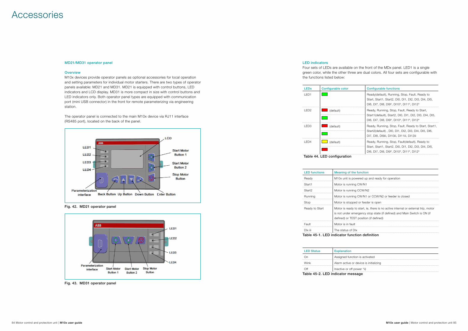
84 Motor control and protection unit | M10x user guide M10x user guide | Motor control and protection unit 85
MD21/MD31 operator panel
OverviewM10x devices provide operator panels as optional accessories for local operation and setting parameters for individual motor starters. There are two types of operator panels available: MD21 and MD31. MD21 is equipped with control buttons, LED indicators and LCD display. MD31 is more compact in size with control buttons and LED indicators only. Both operator panel types are equipped with communication port (mini USB connector) in the front for remote parameterizing via engineering station.
The operator panel is connected to the main M10x device via RJ11 interface (RS485 port), located on the back of the panel.
Fig. 42. MD21 operator panel
Fig. 43. MD31 operator panel
LED indicatorsFour sets of LEDs are available on the front of the MDx panel. LED1 is a single green color, while the other three are dual colors. All four sets are configurable with the functions listed below:
LEDs Configurable color Configurable functions
LED1 Ready(default), Running, Stop, Fault, Ready to Start, Start1, Start2, DI0, DI1, DI2, DI3, DI4, DI5, DI6, DI7, DI8, DI9iii, DI10iii, DI11iii, DI12iii
LED2 (default) Ready, Running, Stop, Fault, Ready to Start, Start1(default), Start2, DI0, DI1, DI2, DI3, DI4, DI5, DI6, DI7, DI8, DI9iii, DI10iii, DI11iii, DI12iii
LED3 (default) Ready, Running, Stop, Fault, Ready to Start, Start1, Start2(default) , DI0, DI1, DI2, DI3, DI4, DI5, DI6, DI7, DI8, DI9iii, DI10iii, DI11iii, DI12iii
LED4 (default) Ready, Running, Stop, Fault(default), Ready to Start, Start1, Start2, DI0, DI1, DI2, DI3, DI4, DI5, DI6, DI7, DI8, DI9iii, DI10iii, DI11iii, DI12iii
Table 44. LED configuration
LED functions Meaning of the function
Ready M10x unit is powered up and ready for operation
Start1 Motor is running CW/N1
Start2 Motor is running CCW/N2
Running Motor is running CW/N1 or CCW/N2 or feeder is closed
Stop Motor is stopped or feeder is open
Ready to Start Motor is ready to start, ie, there is no active internal or external trip, motor is not under emergency stop state (if defined) and Main Switch is ON (if defined) or TEST position (if defined)
Fault Motor is in fault
DIx iii The status of DIxTable 45-1. LED indicator function definition
LED Status Explanation
On Assigned function is activated
Wink Alarm active or device is initializing
Off Inactive or off power *ii)Table 45-2. LED indicator message
Accessories

86 Motor control and protection unit | M10x user guide M10x user guide | Motor control and protection unit 87
If MDx is under parameterization with parametering cable plugged in or scrolling through setting menus, all LEDs in the front panel wink at the same time.
DI9~DI12 are only active for M10x 24VDC type.
Additional label of LED should be prepared, if LED is not assigned to default function.
(i)
(ii)
(iii)
Control buttonsMD21 provides 7 buttons and MD31 provides 3.
User can control motor via buttons on MD21 and MD31. User can also control motor, monitor and parameterize via buttons on MD21.
Button Function Remark
Start 1 button, to start motor CW/N1
Start 2 button, to start motor CCW/N2
Stop button, to stop motor Also used to reset fault trip
Enter button, to enter selected menu Only in MD21
Down button, to show next messages or menus Only in MD21
Up button, to show past messages or menus Only in MD21
Back button, to exit selected menu or go back one step.
Only in MD21
Table 46. MD21/31 Button Icons
Monitoring value displayAfter power on, MD21 initially enters monitoring values display stage, during which all values, alarms, trips and control authority can be displayed.
Fig. 44. View of monitoring value display window
Page title: At the top of the LCD to show the tag name. Main display area: Main display area to display process data. Indication type: At the left side of the bottom of the LCD to show the type of the indication (alarm/trip). Indication text: Following Indication type to show the detail alarm/trip message Control authority: show control access
Icon Meaning
Alarm
Trip
Local control is active
Remote control is active
01, highlighted, DI1* status is closed
02, not highlighted, DI2* status is open
Table 47. Description of icons displayed on MD21
* The number stands for the port of DI. Status of each DI is available on MD21.

88 Motor control and protection unit | M10x user guide M10x user guide | Motor control and protection unit 89
Displaying parametersMD21 supports up to 13 running parameter windows/pages. Users are free to choose any or all of the parameters to be shown on MD panel and mask out unwanted information.
User can navigate through displaying pages by pressing up or down button.
Page no. Page title M101 M102
1 Current (A)
2 Current (%)
3 Line Voltage -
4 Power related (include power, apparent power, power factor) -
5 Thermal capacity
6 Frequency -
7 Energy -
8 Ground current
9 PTC -
10 Time to TOL trip/reset
11 DI status
12 Startup time
13 Current unbalance
Table 48. Parameters on different displaying page
i) Enter button is NOT active when scrolling through running parameter windows. ii) Table 48 shows the actual sequence of displaying pages on MD21.
Alarm messageAlarm message will come up on the bottom of the display window as shown in Fig. 44 with indication icon whenever an alarm is active. Possible alarm messages include the following:
* M102 only.
Thermal capacityPhase unbalanceEarth faultAutoreclose *PTC short circuit*Serial communication Watchdog
OverloadUnderloadPTC *FeedbackPTC open circuit*Running timeReady to trip reset
Phase failureNoload Undervoltage *Welded contactorStart limitationStart numberDI
Trip messageTrip message will come up on the bottom of the display window as shown in Fig. 44 with indication icon whenever a trip is active. Possible trip messages include the following,
*M102 only.
TOL Phase unbalanceEarth faultFeedbackFeeder tripExternal tripMain switch off
Stalled rotorUnderloadPTC *Serial communication failureLong startDI
Phase failureNoloadUndervoltage *Start limitationEmergency stop Current feedback
The menu treePress the back button at monitoring value display window to enter the main configuration menu.
Fig. 45. View of menu
Press the back button at the main configuration menu to enter running parameter window.
Page title: At the top of the LCD to show the tag name or submenu table.
Highlighted item: The current active menu item.
Current number: At the right of the top of the LCD to show the number of the current selected menu item.
Total number: At the right of the top of the LCD to show total menu item numbers in the current page.
Hints: At the bottom of the LCD to describe the current highlighted item or the related value of the highlighted item.

90 Motor control and protection unit | M10x user guide M10x user guide | Motor control and protection unit 91
Press up/down button, can move the highlight to previous/next items.
Press enter button to enter next level of menu.
Press back button to go back to previous level of menu.
Fig. 46. View of main configuration menu tree
ParameterWithin this submenu, all motor related parameters can be configured. Table 49 shows the organization of the different parameter masks in the menu tree.
For more details about parameters, please refer to the document: M10x parameter description.
Level 1 Level 2 Level 3 Level 4 Level 5
Parameter1 Protection
TOL2
Function
Disabled duration start9
Reset mode9
Thermal mode9
TOL bypass9+10
T69+10
Cool coe. 9
Te9+11
Ia/In9+11
Alarm level9
Trip level9
Reset level9
Ambient temperature9
Stall2
Function
Reset mode9
Trip level9
Trip delay9
Phase failure2
Function
Reset mode9
Alarm level9+12
Trip level9
Trip delay9
Unbalance2
Function
Reset mode9
Alarm level9+12
Trip level9
Trip delay9
Underload2
Function
Reset mode9
Alarm level9+12
Trip level9
Trip delay9
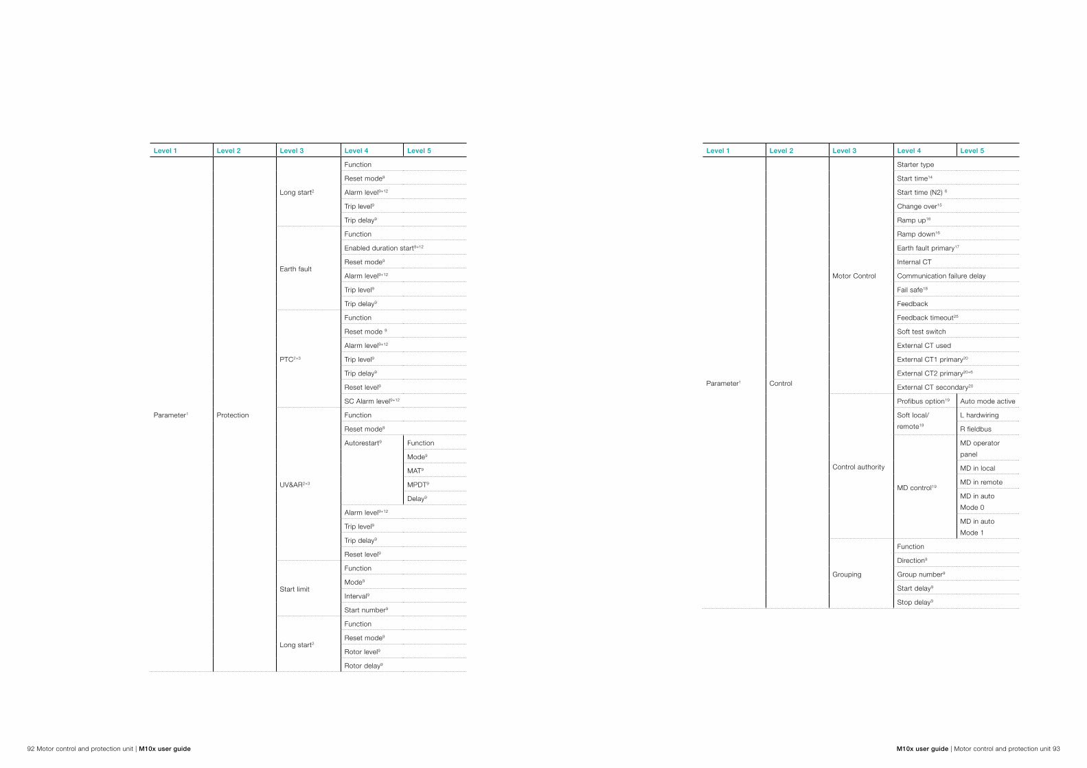
92 Motor control and protection unit | M10x user guide M10x user guide | Motor control and protection unit 93
Level 1 Level 2 Level 3 Level 4 Level 5
Parameter1 Protection
Long start2
Function
Reset mode9
Alarm level9+12
Trip level9
Trip delay9
Earth fault
Function
Enabled duration start9+12
Reset mode9
Alarm level9+12
Trip level9
Trip delay9
PTC2+3
Function
Reset mode 9
Alarm level9+12
Trip level9
Trip delay9
Reset level9
SC Alarm level9+12
UV&AR2+3
Function
Reset mode9
Autorestart9 Function
Mode9
MAT9
MPDT9
Delay9
Alarm level9+12
Trip level9
Trip delay9
Reset level9
Start limit
Function
Mode9
Interval9
Start number9
Long start2
Function
Reset mode9
Rotor level9
Rotor delay9
Level 1 Level 2 Level 3 Level 4 Level 5
Parameter1 Control
Motor Control
Starter type
Start time14
Start time (N2) 6
Change over15
Ramp up16
Ramp down16
Earth fault primary17
Internal CT
Communication failure delay
Fail safe18
Feedback
Feedback timeout25
Soft test switch
External CT used
External CT1 primary20
External CT2 primary20+6
External CT secondary20
Control authority
Profibus option19 Auto mode active
Soft local/remote19
L hardwiring
R fieldbus
MD control19
MD operator panel
MD in local
MD in remote
MD in auto Mode 0
MD in auto Mode 1
Grouping
Function
Direction9
Group number9
Start delay9
Stop delay9

94 Motor control and protection unit | M10x user guide M10x user guide | Motor control and protection unit 95
Level 1 Level 2 Level 3 Level 4 Level 5
Parameter1
Communication
MODBUSRTU4
Address
Parity
Redundancy
Baud rate
ProfibusDPV15
Address
Mode
Block DP
Motor info.
Motor type
Voltage3
Frequency
Rated power
In
In (N2) 6
DI
Type
DI0
Function
Contact type
Delay21
Operation22
DI1
Function
Contact type
Delay21
Operation22
DI2
Function
Contact type
Delay21
Operation22
DI3
Function
Contact type
Delay21
Operation22
DI4
Function
Contact type
Delay21
Operation22
Level 1 Level 2 Level 3 Level 4 Level 5
Parameter1DI
DI5
Function
Contact type
Delay21
Operation22
DI6
Function
Contact type
Delay21
Operation22
DI7
Function
Contact type
Delay21
Operation22
DI8
Function
Contact type
Delay21
Operation22
DI97
Function
Contact type
Delay21
Operation22
DI107
Function
Contact type
Delay21
Operation22
DI117
Function
Contact type
Delay21
Operation22
DI127
Function
Contact type
Delay21
Operation22

96 Motor control and protection unit | M10x user guide M10x user guide | Motor control and protection unit 97
Level 1 Level 2 Level 3 Level 4 Level 5
Parameter1
DO
DO1
Function
Delay23
Principle24
DO23
Function
Delay23
Principle24
Maintenance
Running hourFunction
Alarm level9
Start numberFunction
Alarm Level9
Table 49. Menu tree of parameter
Note: Items with marks will only display when they meet corresponding conditions shown below.
1: MD21 is connected with New Series M10x-x.
2: Starter type is NOT set to be Feeder.
3: MD21 is connected to M102-x.
4: MD21 is connected to M10x-M.
5: MD21 is connected to M10x-P.
6: Starter type is set to be NR_2N|NR_2N Dahlander.
7: MD21 is connected to M10x-x with 24V DI ports.
8: Backup parameter has ever been performed at least once.
9: Related Function is set to be On.
10: TOL Thermal mode is set to be Standard.
11: TOL Thermal mode is set to be EExe.
12: Related Function is set to be Alarm only.
13: MD21 is connected to M101-x.
14: Starter type is NOT set to be NR_softstarter|REV_softstarter.
15: Starter type is set to be NR_S_ D|NR_2N|Dahlander|Autotransformer.
16: Starter type is set to be NR_softstarter|REV_softstarter.
17: Earth fault Function is set to be “On|Alarm only.
18: “Comm. F Delay” is NOT set to be “255”.
19: Details refer to Control Authority chapter
20: Ex CT Used is set to be Yes.
21: Related Function is set to be “Start1/Start2/Stop/ Process interlock1/Process interlock2”.
22: Related Function is set to be Process interlock1/ Process interlock2/Emergency stop.
23: Related “Function” is set to be EnSaD/DeSoD/EFTrip.
24: Related Function is set to be Trips/EFTrip/TOL/WDog/Comm_ Failure/CTRWelded”.
25: Feedback is set to Enabled.

98 Motor control and protection unit | M10x user guide M10x user guide | Motor control and protection unit 99
Operator panelWithin this submenu, LCD display and LED indication can be configured. Table 50 shows the organization of the different parameter masks in the menu tree.
For more details about parameters, please refer to the document: M10x Parameter Description.
Level 1 Level 2 Level 3
Operator panel
LCD display
Current (A)
Current (%)
Line voltage1
Power related1
Thermal capacity
Frequency1
Energy1
Ground current
PTC1
Time to TOL trip/reset
DI status
Startup time
Current unbalance
LED indication
LED1 Function
Color
LED2 Function
Color
LED3 Function
Color
LED4 Function
Color
Language
Password setupTable 50. Menu tree of operator panel
* M102 only.
Time settingWithin this submenu, actual time can be configured. Table 51 shows the organization of the different parameter masks in the menu tree.
Level 1 Level 2
Time setting Year
Month
Day
Hour
Minute
Second
WeekTable 51. Menu tree of time setting
MaintenanceWithin this submenu, all motor related maintenance can be configured. Table 52 shows the organization of the different parameter masks in the menu tree.
Level 1 Level 2
Maintenance SOE*
Running time
Stop time
Start number
Stop number
Trip number
Last trip currentTable 52. Menu tree of maintenance
* M102 only.

100 Motor control and protection unit | M10x user guide M10x user guide | Motor control and protection unit 101
Product informationWithin this submenu, information of M10x and MD21 can be read. Table 53 shows the organization of the different parameter masks in the menu tree.
Level 1 Level 2
Product information Fieldbus address
Type of M10x
Firm version of M10x
Firm version of MDTable 53. Menu tree of product information
Backup and downloadThe backup feature is for reading parameters from the M10x device and creating a backup file in the MD panel. The download feature is for downloading backup files from MD panel to M10x device.
This feature is easy to operate onsite, and is quite useful when similar parameters are required for several M10x devices.
Table 54 shows the organization of the different parameter masks in the menu tree.
Level 1 Level 2
Backup and download Backup parameter
Download backup1Table 54. Menu tree of backup and download
1) The download backup option is not available until the backup parameter function has been executed.
2) Remember to change slave address after copying parameters from other devices to avoid communication problems.
Backup parameter: Saves current parameter to backup register in MD21.
Download backup: Downloads the parameter in backup register into M10x.
TestSelect this submenu, M10x will test itself for a few seconds and feedback.
Test function is only for the manufacturer.
Adjusting parametersSelect the item at the last parameter level and press enter. A password window will appear. Input the correct password to enter the parameter adjusting window.
Fig. 47. Process of entering parameter adjusting window
1) Default password is 1111.
It is recommended to change the default password after first login.
There are two types of parameter adjusting window: numerical value adjusting, and option selecting.
When finished, press the back button to return to the confirmation window. Select confirm and press enter to download the new parameter to the M10x.
Fig. 48-1. Confirm parameter adjustment
The slave address can be revised and downloaded to M10x via MD21.

102 Motor control and protection unit | M10x user guide M10x user guide | Motor control and protection unit 103
Adjusting a numerical valueThis type of window allows a numerical value to be specified within given limits. Pressing up/down buttons will increase/decrease the digit. Once the value is set, press enter to acknowledge.
i) The information of given limits of parameters is provided in the document: M10x Parameter Description.
ii) Continuing to press the up/down button to change the speed of increase/decrease.
iii) When the value reaches the limit, it will automatically count backwards even if the same button is pressed.
The following example shows how to set the startup time to 10sec:
Fig. 48-2. Example of numerical value adjusting
Start editing the value by pressing the up button. When it reaches 10, press enter.
Selecting an option from a listThis type of window allows an item to be selected from a given list of options. With the up/down keys you can scroll through the list. The highlighted selection shows current position within the list. Press enter to confirm, then press back to exit.
Pressing the back button exits the dialog and discards the selection.
i) The details of given options of parameters can be found in the document: M10x Parameter Description.
The following example shows how to set the starter type to NR_2N Dahlander:
Fig. 49. Example of options selecting
Parameterization portThe parameterization port on MD panel is a mini USB type of interface. Once this port is connected with parametering cable, the communication between M10x main device and MD panel is temporarily stopped with a parameterizing status message shown on LCD. No operation is allowed during parameterizing.
M10x parameters can be uploaded and downloaded from the parameterization device via the interface.
Remember to cover up the mini USB port after parameterization is finished.

104 Motor control and protection unit | M10x user guide M10x user guide | Motor control and protection unit 105
Connection
Operator panel is connected to the X2 terminal on M10x via RJ11 interface. The connection shown below includes power supply and communication.
Fig. 50. Connection between M10x and MDx
If MD21 cannot receive information from M10x, a No Comm. message will appear on the LCD display.
If MD21 receives incorrect information from M10x, a comm. Error message will appear on the LCD display.
Parameterization software: MCUsetup
MCUsetup software is used to set parameters. It exchanges data with M10x via RS485.
Fig. 51. Parameterization interface
Fig. 52. MCUSetup window
The parameterization software includes the following functions: Edit parameters Export parameter to a file Import parameter from a file Update M10x’s parameters Download M10x’s parameters Read M10x’s parameters User management
The parameterization software can run on all of the following PC operation systems: Windows 2000, Windows XP, Win 7 and Win 8.
For more information on how to set parameters with MCUSetup software, please refer to separate document: MCUSetup User Guide.

106 Motor control and protection unit | M10x user guide M10x user guide | Motor control and protection unit 107
Appendix A: Technical data
Technical data
Main circuit
Rated operation voltage (Ue) up to 400/690VAC
Rated insulation voltage (Ui) 690VAC
Rated impulse withstand voltage (Uimp) 6KV, overvoltage category II in IT network, Category III in other networks.
Degree of pollution 3
Rated operation current (Ie) 0.24-63A
Rated frequency 50/60Hz
Control circuit
Rated operational voltage (Ue) 24V DC ,110 or 240 VAC
Rated insulation voltage (Ui) -250VAC
Rate impulse withstand voltage (Uimp) 4kV for AC circuit
Rated operational current (Ie)
Contactor control relay output(CCA,CCB,CCC)
2A /24VDC(DC-13) 4A/120VAC(AC-15)2A/240VAC(AC-15)
Rated frequency 50/60 Hz
Response timing accuracy
TOL protection 5% of tolerance of tripping time
Stall protection 200 ~ 350ms
Earth fault protection -30~+30ms
PTC protection 400 ~ 500ms
Others 0 ~ 150ms
Power supply
Rated operational voltage (Ue) 24VDC , 110 or 240VAC
Voltage operation range 85%-110% Ue
Power consumption
24VDC 110VAC 240VAC
Typical 5W 6VA 12VA
Maxium 8W - -
Maximum starting current 600mA - -
Digital input(DC)
Number of digital inputs 13 with one common connection
Logic 1 15…30V
Logic 0 0…5V
Digital input (AC)
Number of digital inputs 9 with one common connection
Logic 1 110VAC type, 79…110V240VAC type, 164…240V
Logic 0 110VAC type, 0…20V240VAC type, 0…40V
Fieldbus interface
Protocol PROFIBUS-DP/MODBUS RTU
Baud rate PROFIBUS DP 9.6kbps/19.2kbps/45.45kbps/93.75Kbps/187.5Kbps/500Kbps/1.5Mbps
MODBUS RTU1200/4800/9600/19200/38400/57600 bps
Fieldbus capacity 32 nodes per segment
Degree of protection
M10x IP20
MD21/MD31 IP54 from module front

108 Motor control and protection unit | M10x user guide M10x user guide | Motor control and protection unit 109
Environmental conditions
Storage -40 ~ +85°C
Normal operation 24VDC type
110/240VAC type
-10 ~ +60°CVertical mounting: -10 ~ +60°CHorizontal mounting: -10 ~ +55°C
Humidity 15% up to 95% without dew
Derating accepted operating altitude 4500m
Without derating operating altitude 2000m
EMC environment 1) Equipments in the system complies with EMC requirement of CE/CCC certificate.
2) Power supply system complies with IEC61000-2-1, IEC61000-2-2, especially the system in which VSD/frequency converters are used.
Metering accuracy
Phase current Range: 0.4-8 ×phase CT primary ampsAccuracy: ±2% or ±0.01A, whichever is greater
Earth fault current Full scale: 1.2 × RCT nominal currentAccuracy: ±2% RCT primary
Line voltage (M102 only) Voltage metering range: 110V - 690V Accuracy: ±2%
Power (only for M102) Accuracy: ±5% or ±0.1kW, whichever is greater
Thermistor input (only for M102) Sensor type: positive temperature coefficient PTC RHOT=100-10,000 ΩAccuracy: ±2% or 10Ω which is greater
Installation
Mounting
MCU On TS35 DIN rail
With 3 screws ST4.2 (tightening torque 4.5Nm)
With 2 screws (tightening torque 0.1Nm)
Mounting position (MCU) Vertical (DIN and screw)
Horizontal (screw only)
Dimension MCU 110mm X 140mm X 75mm
MD21 91mm X 75mm X 24.3mm
MD31 88mm X 50mm X 24.3mm
Wiring size Terminal X1 DC type 1.5mm2
AC type 2.5mm2
Terminal X3 2.5mm2
Terminal X4 2.5mm2
Tightening torque
Metering accuracy
Phase current Range: 0.4-8 ×phase CT primary ampsAccuracy: ±2% or ±0.01A, whichever is greater
Earth fault current Full scale: 1.2 × RCT nominal currentAccuracy: ±2% RCT primary
Line voltage (only for M102) Voltage metering range: 110V - 690V Accuracy: ±2%
Power (only for M102) Accuracy: ±5% or ±0.1kW, whichever is greater
Thermistor Input (only for M102) Sensor type: positive temperature coefficient PTC RHOT=100-10,000 ΩAccuracy: ±2% or 10Ω which is greater
Standards
Low voltage switchgears
IEC60947-1 Low voltage switchgear and control gear” Part1: General rules
IEC60947-4-1 Low voltage switchgear and control gear” Part4: Contactors and motor-starters, Section one-Electromechanical contactors and motor-starters
EMC
Electrostatic discharge IEC61000-4-2, Level 3
Electromagnetic field immunity IEC61000-4-3, Level 3
Electrical fast transient/burst immunity IEC61000-4-4 Power suply, Level 4Others, Level 3
Surge immunity IEC61000-4-5, Level 3
Conducted disturbance immunity IEC61000-4-6, Level 3
Radiated disturbance EN55011/CISPR 11, Class A*Refer to section "Earth fault protection" on page 51

Contact us
ABB Low Voltage SystemsLocal contacts atwww.abb.com/mns
ArgentinaTel. +54112295500
AustraliaTel. +61297537170
BeneluxTel. +31104078663
BrazilTel. +551124328010
CanadaTel. +15144203100
ChinaTel. +865926038118
CzechTel. +420543145111
DenmarkTel. +4544504450
EgyptTel. +20226251300
EstoniaTel. +3726801800
FinlandTel. +358102221999
FranceTel. +33388556700
GermanyTel. +496203712816
GreeceTel. +302102891807
IndiaTel. +918022948905
ItalyTel. +3903714531
KazakhstanTel. +77272583838
KoreaTel. +82415292467
MalaysiaTel. +60356284888
MexicoTel. +525536019708
NorwayTel. +4735582000
PolandTel. +48713858300
QatarTel. +97444253888
RussiaTel. +74957772220
Saudi ArabiaTel. +96612653030
SingaporeTel. +6567765711
South AfricaTel. +27102025000
SpainTel. +34934842121
SwedenTel. +4621325000
SwitzerlandTel. +41844845845
ThailandTel. +6626651000
TurkeyTel. +902165816800
UAETel. +97143147500
United KingdomTel. +441915144555
USATel. +16174816047
Publ
icat
ion
No.
1TN
C91
1112
D02
06