motor contactor j7kn - omron · 2 motor contactor j7kn contactors ratings rated current no. of...
TRANSCRIPT

Motor Contactor J7KN 1
Motor Contactor
J7KN• Range from 4 to 500 kW (AC 3, 380/415 V)
• AC and DC operated
• Integrated auxiliary contacts; integrated aux. contact of J7KN contactors up to 11kW suitable for electronic circuits
• Screw fixing and snap fitting (35 mm DIN rail) up to 37 kW
• Compliant to the global standards• Finger proof (BGV A2)
• System contactors for Fuseless Load Feeders with integrated link modules
• All needed approvals like CE, UL, GOST & CCC. The J7KN fulfills the following standards; IEC 947-4-1, VDE 0660 and EN 60947-4-1.
• Accessories like auxiliary contacts front or/and side mounted, mechanical interlock and suppressor units.
• Mirror Contacts (NC) according to IEC 60947-4-1 for safety applications
Model Number Legend1. Motor Contactors
1) Motor Contactor2) G for low DC control power consumption3) Rated Motor Current.
D for integrated aux. contact for electronic circuits (except for 4-pole versions)
4) Integrated auxiliary contact configuration5) Coil voltage6) D for DC coil supply
2. Aux. Contact Modules for Motor Contactors
1) Auxiliary Contact Modules2) Motor contactors size3) Combination of NO / NC contacts4) Place of mounting
3. Accessories for Motor Contactors (Pneumatic Timers)
1) Accessories for Motor Contactor2) Motor contactors size3) Pneumatic Timer4) Time range5) Function
4. Accessories for Motor Contactors (Mechanical Interlock)
1) Accessories for Motor Contactor2) Motor contactors size3) Mechanical Interlock
5. Accessories for Motor Contactors (RS Suppressor units)
1) Accessories for Motor Contactor2) Motor contactors size3) RS-surge suppressors4) Voltage
6. Accessories for Motor Contactors (RC Suppressor units)
1) Accessories for Motor Contactor2) C2 = J7KN3) RC = RC suppressor unit4) Voltage
7. Accessories for Motor Contactors (Additional Terminals and Terminal Covers)
1) Accessories for Motor Contactor2) Version
8. Insulated wiring systems for Motor Contactors
1) Additional reference for LVSG2) WKR = Wiring Kit Reverser;
WKSD = Wiring Kit Star Delta3) Version
J7KN#-###-##-### # 1 32 4 5 6
J73KN-#-##-##1 32 4
J74KN-#-##-##-##1 32 4 5
J74KN-#-##1 32
J74KN-#-##-###1 3 42
J74KN-##-##-###1 3 42
J74KN-####1 2
J74-WK##-##1 2 3

2 Motor Contactor J7KN
■ ContactorsRatings Rated
currentNo. of Poles
Control circuitPower consum.
Aux. Contacts Partnumber
AC2, AC3 AC1 AC type VA Built-in Additional Type*1 Add. suffix for
DC type W front side Voltage 24specification 48
110230
DC typescoil voltage
380 V400 V415 VkW
500 V
kW
660 V690 V
kW
690 V
A Inrush Hold NO NC*2
Number of con-tacts
Numberof con-tacts D
4 5,5 5,5 25
333-45 7-10
1 –
4
–
J7KN-10D-10 @@@–– 1 J7KN-10D-01 @@@
4 – – J7KN-10D-4 @@@
33 3
1 – J7KNG-10-10 @@@
D
– 1 J7KNG-10-01 @@@4 – – J7KNG-10-4 @@@
3 75 21 –
3J7KN-10D-10 @@@
– 1 J7KN-10D-01 @@@
5,5 7,5 7,5 25
333-45 7-10
1 –
4
–
J7KN-14D-10 @@@–– 1 J7KN-14D-01 @@@
4 – – J7KN-14D-4 @@@
33 3
1 – J7KNG-14-10 @@@
D
– 1 J7KNG-14-01 @@@4 – – J7KNG-14-4 @@@
3 75 21 –
3J7KN-14D-10 @@@
– 1 J7KN-14D-01 @@@
7,5 10 10 32
333-45 7-10
1 –
4
–
J7KN-18D-10 @@@–– 1 J7KN-18D-01 @@@
4 – – J7KN-18D-4 @@@
33 3
1 – J7KNG-18-10 @@@
D
– 1 J7KNG-18-01 @@@4 – – J7KNG-18-4 @@@
3 75 21 –
3J7KN-18D-10 @@@
– 1 J7KN-18D-01 @@@
11 10 10 32
333-45 7-10
1 –
4
–
J7KN-22D-10 @@@–– 1 J7KN-22D-01 @@@
4 – – J7KN-22D-4 @@@
33 3
1 – J7KNG-22-10 @@@
D
– 1 J7KNG-22-01 @@@4 – – J7KNG-22-4 @@@
3 75 21 –
3J7KN-22D-10 @@@
– 1 J7KN-22D-01 @@@
J7KN-ACJ7KNGJ7KN-DC
11 15 15 50 3
90-115 9-13
– –4
4
J7KN-24 @@@ –
4 4 J7KNG-24 @@@D
140 2 3 J7KN-24 @@@
15 18,5 18,5 65 3
90-115 9-13
– –4
J7KN-32 @@@ –
4 4 J7KNG-32 @@@D
140 2 3 J7KN-32 @@@
18,5 18,5 18,5 80 3
90-115 9-13
– –4
J7KN-40 @@@ –
4 4 J7KNG-40 @@@D
140 2 3 J7KN-40 @@@
J7KN-ACJ7KN-DC
22 30 30 110 3140-185 13-18
– –4
4
J7KN-50 @@@ –
200 6 3 J7KN-50 @@@ D
30 37 37 120 3140-185 13-18
– –4 J7KN-62 @@@ –
200 6 3 J7KN-62 @@@ D
37 45 45 130 3140-185 13-18
– –4 J7KN-74 @@@ –
200 6 3 J7KN-74 @@@ D
J7KN-AC
J7KNG
J7KN-DC

Motor Contactor J7KN 3
Ratings Ratedcurrent
No. of Poles
Control circuitPower consum.
Aux. Contacts Partnumber
AC2, AC3 AC1 AC type VA Built-in Additional Type*1
*1 For more coil voltages refer to Appendix.
DC type W front side Voltage 24specification 48
110230
380 V400 V415 VkW
500 V
kW
660 V690 V
kW
690 V
A Inrush Hold NO NC*2
*2 Mirror Contact (NC) according to IEC 60947-4-1 for safety applications
Number of con-tacts
Numberof con-tacts
J7KN-90/115
45 55 55 160
3
190-280 VA 2.5-5 VA
– – 7 4
J7KN-90 @@@ *3
*3 Universal Current models (AC and DC operated)
55 55 55 200 280 W 5 W J7KN-115 @@@ *3
J7KN-151/176
75 75 75 2303
350 5 – – 4 2
J7KN-151 @@@ *3
4 J7KN-151-4 @@@ *3
90 90 90 2503 J7KN-176 @@@ *3
4 J7KN-176-4 @@@ *3
J7KN-210 to 316
110 160 160 350
3 360 5 – – 4 4
J7KN-210 @@@ *3
132 210 210 450 J7KN-260 @@@ *3
160 250 250 500 J7KN-316 @@@ *3
J7KN-450 to 860
250 375 375 600
3
800-950 VA 9-11 VA
2 2 4 –
J7KN-450-22 @@@ *3
300 475 475 760 750-850 W 8-10 W J7KN-550-22 @@@ *3
400 630 630 1000 1350-1600 VA
21-25 VA J7KN-700-22 @@@ *3
500 700 700 1100 1300-1550 W 18-22 W J7KN-860-22 @@@ *3

4 Motor Contactor J7KN
■ Additional productsAuxiliary Contacts Blocks
Pneumatic Timer
Mechanical Interlocks
Rated Operational Current Mounting + comments Contacts Suitable for Contactors
Partnumer
AC15 AC15 AC1230V 400V 690V
A A A NO NC*1 Type
3 2 10Front, standard version
1 –
J7KN-10D up to J7KN-115
J73KN-B-10*2
3 2 10 – 1 J73KN-B-01*2
3 2 10 EM/LB version (early make/late break)
1 – J73KN-B-10U*2
3 2 10 – 1 J73KN-B-01U*2
6 4 25High current version
1 – J73KN-B-10A*2
6 4 25 – 1 J73KN-B-01A*2
3 2 10 Side version, max.2 pcs per contactor 1 1 J7KN-24 up to
J7KN-115 J73KN-C-11S*2
3 2 10
Front version, max. 1 pcs per contactor
1 1
J7KN-151 up to J7KN-316
J73KN-D-11F
3 2 10 2 2 J73KN-D-22F
3 2 10 Side version, max. 2 pcs per contactor 1 1 J7KN-151 up to
J7KN-316 J73KN-D-11S
3 2 10 Front version, max.1 pcs per contactor 2 2 J7KN-450 up to
J7KN-860 J73KN-E-22F
*1 Mirror Contact (NC) according to IEC 60947-4-1 for safety applications. *2 Contacts suitable for electronic circuits, according to IEC60947-5-4 for rated voltage 24 VDC (test ratings 17 VDC, 5 mA). Positively guid-
ed contacts. Technical data see page 24.
Function Time range s
Mounting + comments
Contacts Suitable for Contactors Partnumber
TypeNO NC NO NC
On-delay 0.1 - 40
Front
1 1 – –
Front for contactors J7KN-10D up to J7KN-40
J74KN-B-TP40DA
On-delay 10 - 180 1 1 – – J74KN-B-TP180DA
Off-delay 0.1 - 40 – – 1 1 J74KN-B-TP40IA
Off-delay 10 - 180 – – 1 1 J74KN-B-TP180IA
Interlocks contactors with contactors (dimensions need to be the same)Type
PartnumberType
J7KN(G)-10(D) - J7KN(G)-40 + J7KN(G)-10(D) - J7KN(G)-40 J74KN-B-ML
J7KN-24 - J7KN-74 + J7KN-24 - J7KN-74 J74KN-C-ML
J7KN-90 - J7KN-115 + J7KN-90 - J7KN-115 J74KN-D2-ML
J7KN-151 - J7KN-316 + J7KN-151 - J7KN-316 J74KN-E-ML

Motor Contactor J7KN 5
Suppressor units
Additional products
Insulated wiring systems for motor contactors
Function For Contactors Voltages PartnumberType
RC-Unit snap on contactor J7KN-10D - J7KN-74 12 - 48 V AC/DC48 - 127 V AC/DC110 - 230 V AC/DC230 - 415 V AC/DC
J74KN-C2-RC24J74KN-C2-RC110J74KN-C2-RC230J74KN-C2-RC400
Function For Contactors Specification Partnumber
Cable Cross-section to clamp mm2
solid or stranded flexible
flex. with multicore cable end Type
Terminals single pole J7KN-50 - J7KN-74 4 - 35 6 - 25 4 - 25 J74KN-LG-9030(3pcs set)
J7KN-151 - J7KN-176 16 - 120 – 16 - 95 J74KN-LG-11224
Terminal cover for terminal protection according DIN 57106, BVG-A2
J7KN-151 - J7KN-176 3-pole
for 3 terminals; 2 units for one con-tactor
J74KN-LG-10404
J7KN-210 - J7KN-316 J74KN-LG-11457
Marking system for contactors and aux. contactblocks
J7KN-10 to J7KN-74& J73KN-B
2-section without marking, divisible
J74KN-P487-1
4-section without marking, divisible
J74KN-P245-1
Function For Contactors Specification Partnumber
Maximum current Type
For reversing contactors (2 parts)
J7KN-10D - J7KN-22D 22 J74-WKR-B2
J7KN-24 - J7KN-40 40 J74-WKR-C
For star-delta combination (4 parts)
J7KN-10D - J7KN-22D 22 J74-WKSD-B2
J7KN-24 - J7KN-40 40 J74-WKSD-C
6 Motor Contactor J7KN
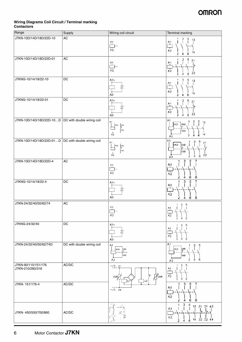
Wiring Diagrams Coil Circuit / Terminal markingContactors
Range Supply Wiring coil circuit Terminal marking
J7KN-10D/14D/18D/22D-10 AC
J7KN-10D/14D/18D/22D-01 AC
J7KNG-10/14/18/22-10 DC
J7KNG-10/14/18/22-01 DC
J7KN-10D/14D/18D/22D-10…D DC with double wiring coil
J7KN-10D/14D/18D/22D-01…D DC with double wiring coil
J7KN-10D/14D/18D/22D-4 AC
J7KNG-10/14/18/22-4 DC
J7KN-24/32/40/50/62/74 AC
J7KNG-24/32/40 DC
J7KN-24/32/40/50/62/74D DC with double wiring coil
J7KN-90/115/151/176 J7KN-210/260/316
AC/DC
J7KN- 151/176-4 AC/DC
J7KN- 450/550/700/860 AC/DC
A2-
A1+
A2-
A1+
A2-
A1+
A2-
A1+
Motor Contactor J7KN 7
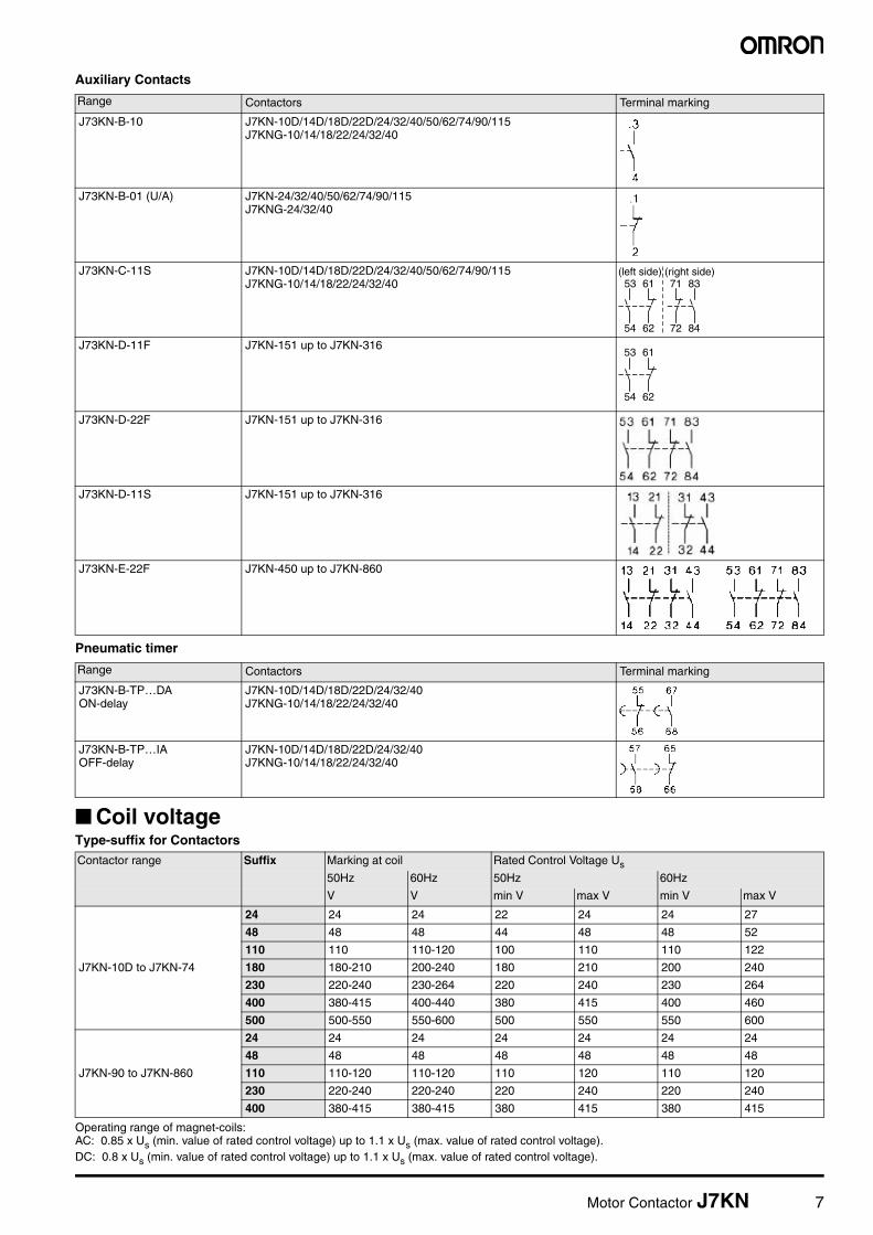
Auxiliary Contacts
Pneumatic timer
■ Coil voltageType-suffix for Contactors
Operating range of magnet-coils:AC: 0.85 x Us (min. value of rated control voltage) up to 1.1 x Us (max. value of rated control voltage). DC: 0.8 x Us (min. value of rated control voltage) up to 1.1 x Us (max. value of rated control voltage).
Range Contactors Terminal marking
J73KN-B-10 J7KN-10D/14D/18D/22D/24/32/40/50/62/74/90/115J7KNG-10/14/18/22/24/32/40
J73KN-B-01 (U/A) J7KN-24/32/40/50/62/74/90/115J7KNG-24/32/40
J73KN-C-11S J7KN-10D/14D/18D/22D/24/32/40/50/62/74/90/115J7KNG-10/14/18/22/24/32/40
J73KN-D-11F J7KN-151 up to J7KN-316
J73KN-D-22F J7KN-151 up to J7KN-316
J73KN-D-11S J7KN-151 up to J7KN-316
J73KN-E-22F J7KN-450 up to J7KN-860
Range Contactors Terminal marking
J73KN-B-TP…DAON-delay
J7KN-10D/14D/18D/22D/24/32/40J7KNG-10/14/18/22/24/32/40
J73KN-B-TP…IAOFF-delay
J7KN-10D/14D/18D/22D/24/32/40J7KNG-10/14/18/22/24/32/40
Contactor range Suffix Marking at coil Rated Control Voltage Us
50Hz 60Hz 50Hz 60Hz
V V min V max V min V max V
J7KN-10D to J7KN-74
24 24 24 22 24 24 27
48 48 48 44 48 48 52
110 110 110-120 100 110 110 122
180 180-210 200-240 180 210 200 240
230 220-240 230-264 220 240 230 264
400 380-415 400-440 380 415 400 460
500 500-550 550-600 500 550 550 600
J7KN-90 to J7KN-860
24 24 24 24 24 24 24
48 48 48 48 48 48 48
110 110-120 110-120 110 120 110 120
230 220-240 220-240 220 240 220 240
400 380-415 380-415 380 415 380 415
53 61
54 62
71 83
72 84
(left side) (right side)
53 61
54 62

8 Motor Contactor J7KN
■ Engineering data and characteristics
Approximate Values for three-phase Motors
Motor Full Load CurrentsApproximate values of motor F.L.C. and minimum „slow blow“ respectively „gL“ short-circuit fuse
The motor F.L.C. be valid for standard internal and surface cooled three-pole motors with 1500 min-1. The fuses values be valid for the motor F.L.C. shown in the table and D.O.L.-start: starting current max. 6x motor F.L.C., starting time max. 5s; star-delta-start: starting current max. 2x motor F.L.C., starting time max. 15s. For motors with higher F.L.C., higher starting current and / or longer starting time, larger short-circuit fuses are required.
The maximum admissible value is dependent on the switchgear respectively thermal overload relay.
Motor rating 220-230V Motor 240V Motor 380-400V Motor 415V Motor 500V Motor 660-690V Motor
Range according to BS for 415V Value of fusing at motor start
Value of fusing at motor start
Value of fusing at motor start
Value of fusing at motor start
Value of fusing at motor start
Value of fusing at motor start
kW PS~hp hp cos %F.L.C.A
D.O.L.A
YDA
F.L.C.A
D.O.L.A
YDA
F.L.C.A
D.O.L.A
YDA
F.L.C.A
D.O.L.A
YDA
F.L.C.A
D.O.L.A
YDA
F.L.C.A
D.O.L.A
YDA
0.06 0.08 - 0.7 59 0.38 1 1 0.35 1 1 0.22 1 1 - - - 0.16 1 1 - - -
0.09 0.12 - 0.7 60 0.55 2 2 0.5 2 2 0.33 1 1 - - - 0.24 1 1 - - -
0.12 0.16 - 0.7 61 0.76 2 2 0.68 2 2 0.42 2 2 - - - 0.33 1 1 - - -
0.18 0.24 - 0.7 61 1.1 2 2 1 2 2 0.64 2 2 - - - 0.46 1 1 - - -
0.25 0.34 - 0.7 62 1.4 4 2 1.38 4 2 0.88 2 2 - - - 0.59 2 2 - - -
0.37 0.5 - 0.72 64 2.1 4 4 1.93 4 4 1.22 4 2 - - - 0.85 2 2 0.7 2 2
0.55 0.75 - 0.75 69 2.7 4 4 2.3 4 4 1.5 4 2 - - - 1.2 4 2 0.9 2 2
0.75 1 1 0.8 74 3.3 6 4 3.1 6 4 2 4 4 2 4 4 1.48 4 2 1.1 2 2
1.1 1.5 1.5 0.83 77 4.9 10 6 4.1 6 6 2.6 4 4 2.5 4 4 2.1 4 4 1.5 4 2
1.5 2 2 0.83 78 6.2 10 10 5.6 10 10 3.5 6 4 3.5 6 4 2.6 4 4 2 4 4
2.2 3 3 0.83 81 8.7 16 10 7.9 16 10 5 10 6 5 10 6 3.8 6 6 2.9 6 4
2.5 3.4 - 0.83 81 9.8 16 16 8.9 16 10 5.7 10 10 - - - 4.3 6 6 - - -
3 4 4 0.84 81 11.6 20 16 10.6 20 16 6.6 16 10 6.5 16 10 5.1 10 10 3.5 6 4
3.7 5 5 0.84 82 14.2 25 20 13 25 16 8.2 16 10 7.5 16 10 6.2 16 10 - - -
4 5.5 - 0.84 82 15.3 25 20 14 25 20 8.5 16 10 - - - 6.5 16 10 4.9 10 6
5.5 7.5 7.5 0.85 83 20.6 35 25 18.9 35 25 11.5 20 16 11 20 16 8.9 16 10 6.7 16 10
7.5 10 10 0.86 85 27.4 35 35 24.8 35 35 15.5 25 20 14 25 16 11.9 20 16 9 16 10
8 11 - 0.86 85 28.8 50 35 26.4 35 35 16.7 25 20 - - - 12.7 20 16 - - -
11 15 15 0.86 87 39.2 63 50 35.3 50 50 22 35 25 21 35 25 16.7 25 20 13 25 16
12.5 17 - 0.86 87 43.8 63 50 40.2 63 50 25 35 35 - - - 19 35 25 - - -
15 20 20 0.86 87 52.6 80 63 48.2 80 63 30 50 35 28 35 35 22.5 35 25 17.5 25 20
18.5 25 25 0.86 88 64.9 100 80 58.7 80 63 37 63 50 35 50 50 28.5 50 35 21 35 25
20 27 - 0.86 88 69.3 100 80 63.4 80 80 40 63 50 - - - 30.6 50 35 - - -
22 30 30 0.87 89 75.2 100 80 68 100 80 44 63 50 40 63 50 33 50 50 25 35 35
25 34 - 0.87 89 84.4 125 100 77.2 100 100 50 80 63 - - - 38 63 50 - - -
30 40 40 0.87 90 101 125 125 92.7 125 100 60 80 63 55 80 63 44 63 50 33 50 35
37 50 50 0.87 90 124 160 160 114 160 125 72 100 80 66 100 80 54 80 63 42 63 50
40 54 - 0.87 90 134 160 160 123 160 160 79 100 100 - - - 60 80 63 - - -
45 60 60 0.88 91 150 200 160 136 200 160 85 125 100 80 100 100 64.5 100 80 49 63 63
51 70 - 0.88 91 168 200 200 154 200 200 97 125 100 - - - 73.7 100 80 - - -
55 75 - 0.88 91 181 250 200 166 200 200 105 160 125 - - - 79 125 100 60 80 63
59 80 80 0.88 91 194 250 250 178 250 200 112 160 125 105 160 125 85.3 125 100 - - -
75 100 100 0.88 91 245 315 250 226 315 250 140 200 160 135 200 160 106 160 125 82 125 100
90 125 125 0.88 92 292 400 315 268 315 315 170 250 200 165 200 200 128 160 160 98 125 125
110 150 150 0.88 92 358 500 400 327 400 400 205 250 250 200 250 250 156 200 200 118 160 125
129 175 175 0.88 92 420 500 500 384 500 400 242 315 250 230 315 250 184 250 200 - - -
132 180 - 0.88 92 425 500 500 393 500 500 245 315 250 - - - 186 250 200 140 200 160
147 200 200 0.88 93 472 630 630 432 630 500 273 315 315 260 315 315 207 250 250 - - -
160 220 - 0.88 93 502 630 630 471 630 630 295 400 315 - - - 220 315 250 170 200 200
184 250 250 0.88 93 590 800 630 541 630 630 340 400 400 325 400 400 259 315 315 - - -
200 270 - 0.88 93 626 800 800 589 800 630 370 500 400 - - - 278 315 315 215 250 250
220 300 300 0.88 93 700 1000 800 647 800 800 408 500 500 385 500 400 310 400 400 - - -
250 340 - 0.88 93 803 1000 1000 736 1000 800 460 630 500 - - - 353 500 400 268 315 315
257 350 350 0.88 93 826 1000 1000 756 1000 800 475 630 630 450 630 500 363 500 400 - - -
295 400 400 0.88 93 948 1250 1000 868 1000 1000 546 800 630 500 630 630 416 500 500 - - -
315 430 - 0.88 93 990 1250 1250 927 1250 1000 580 800 630 - - - 445 630 500 337 400 400
355 483 - 0.89 95 - - - - - - 636 800 800 - - - 483 630 630 366 500 400
400 545 - 0.89 96 - - - - - - 710 1000 800 - - - 538 630 630 410 500 500

Motor Contactor J7KN 9
Approximate values of motor F.L.C. according to CSA and UL
Motor rating
Motor F.L.C. at 110-120V Motor F.L.C. at 220-240V*1
*1 Determine the motor current for 200V and 208V by increasing the values for 220-240V at 200V about 15% and for 208V about 10%.
Motor F.L.C. at 440-480V Motor F.L.C. at 550-600V
1-phase 2-phase 3-phase 1-phase 2-phase 3-phase 1-phase 2-phase 3-phase 1-phase 2-phase 3-phase
hp A A A A A A A A A A A A
½ 9.8 4.0 4.4 4.9 2.0 2.2 2.5 1.0 1.1 2.0 0.8 0.9
¾ 13.8 4.8 6.4 6.9 2.4 3.2 3.5 1.2 1.6 2.8 1.0 1.3
1 16.0 6.4 8.4 8.0 3.2 4.2 4.0 1.6 2.1 3.2 1.3 1.7
1½ 20.0 9.0 12.0 10.0 4.5 6.0 5.0 2.3 3.0 4.0 1.8 2.4
2 24.0 11.8 13.6 12.0 5.9 6.8 6.0 3.0 3.4 4.8 2.4 2.7
3 34.0 16.6 19.2 17.0 8.3 9.6 8.5 4.2 4.8 6.8 3.3 3.9
5 56.0 26.4 30.4 28.0 13.2 15.2 14.0 6.6 7.6 11.2 5.3 6.1
7½ 80.0 38.0 44.0 40.0 19.0 22.0 21.0 9.0 11.0 16.0 8.0 9.0
10 100.0 48.0 56.0 50.0 24.0 28.0 26.0 12.0 14.0 20.0 10.0 11.0
15 135.0 72.0 84.0 68.0 36.0 42.0 34.0 18.0 21.0 27.0 14.0 17.0
20 - 94.0 108.0 88.0 47.0 54.0 44.0 23.0 27.0 35.0 19.0 22.0
25 - 118.0 136.0 110.0 59.0 68.0 55.0 29.0 34.0 44.0 24.0 27.0
30 - 138.0 160.0 136.0 69.0 80.0 68.0 35.0 40.0 54.0 28.0 32.0
40 - 180.0 208.0 176.0 90.0 104.0 88.0 45.0 52.0 70.0 36.0 41.0
50 - 226.0 260.0 216.0 113.0 130.0 108.0 56.0 65.0 86.0 45.0 52.0
60 - - - - 133.0 145.0 - 67.0 77.0 - 53.0 62.0
75 - - - - 166.0 192.0 - 83.0 96.0 - 66.0 77.0
100 - - - - 218.0 248.0 - 109.0 124.0 - 87.0 99.0
125 - - - - - 312.0 - 135.0 156.0 - 108.0 125.0
150 - - - - - 360.0 - 156.0 180.0 - 125.0 144.0
200 - - - - - 480.0 - 208.0 240.0 - 167.0 192.0
250 - - - - - 602.0 - - 302.0 - - 242.0
300 - - - - - - - - 361.0 - - 289.0
350 - - - - - - - - 414.0 - - 336.0
400 - - - - - - - - 477.0 - - 382.0
500 - - - - - - - - 590.0 - - 472.0

10 Motor Contactor J7KN
Contactors
Data according to IEC 60947-4-1, EN 60947-4-1, VDE 0660Main Contacts Type J7KN(G)-10(D) J7KN(G)-14(D) J7KN(G)-18(D) J7KN(G)-22(D) J7KN(G)-24 J7KN(G)-32 J7KN(G)-40 J7KN-50
Rated insulation voltage Ui*1
*1 Suitable at 690V for: earthed-neutral systems, overvoltage I to IV, pollution degree 3 (standard-industry): Uimp = 8kV. Data for other conditions on request.
V AC 690 690 690 690 690 690 690 690
Making capacity Ieff at Ue =690V AC
A 200 200 200 200 400 500 500 700
Breaking capacity Ieff 400V AC A 180 180 200 200 380 400 400 600
J7KN-09 to J7KN-22 cos = 0,65
500V AC A 150 150 180 180 300 370 370 500
J7KN-24 to J7KN-860 cos = 0,35
690V AC A 100 100 150 150 260 340 340 400
1000V AC A – – – – – – – –
Utilization category AC1 Switching of resistive loadRated operational current Ie (=Ith) at 40°C, open
690V A 25 25 32 32 50 65 80 110
Rated operational powerof three-phase resistive loads 50-60Hz, cos = 1
220V kW 9,5 9,5 12,2 12,2 19,0 24,7 30,4 41,9
230V kW 9,9 9,9 12,7 12,7 19,9 25,9 31,8 43,8
240V kW 10,4 10,4 13,3 13,3 20,8 27,0 33,2 45,7
380V kW 16,4 16,4 21,0 21,0 32,9 42,7 52,6 72,3
400V kW 17,3 17,3 22,1 22,1 34,6 45,0 55,4 76,1
415V kW 17,9 17,9 23,0 23,0 35,9 46,7 57,4 79,0
440V kW 19,0 19,0 24,4 24,4 38,1 49,5 60,9 83,7
500V kW 21,6 21,6 27,7 27,7 43,3 56,2 69,2 95,2
660V kW 28,5 28,5 36,5 36,5 57,1 74,2 91,3 125,6
690V kW 29,8 29,8 38,2 38,2 59,7 77,6 95,5 131,3
1000V kW – – – – – – – –
Rated operational currentIe (=Ithe) at 60°C, enclosed
690V A 25 25 32 32 40 55 65 90
Rated operational powerof three-phase resistive loads50-60Hz, cos = 1
220V kW 9,5 9,5 12,2 12,2 15,2 20,9 24,7 34,3
230V kW 9,9 9,9 12,7 12,7 15,9 21,9 25,9 35,8
240V kW 10,4 10,4 13,3 13,3 16,6 22,8 27,0 37,4
380V kW 16,4 16,4 21,0 21,0 26,3 36,2 42,7 59,2
400V kW 17,3 17,3 22,1 22,1 27,7 38,1 45,0 62,3
415V kW 17,9 17,9 23,0 23,0 28,7 39,5 46,7 64,6
440V kW 19,0 19,0 24,4 24,4 30,4 41,9 49,5 68,5
500V kW 21,6 21,6 27,7 27,7 34,6 47,6 56,2 77,9
660V kW 28,5 28,5 36,5 36,5 45,7 62,8 74,2 102,8
690V kW 29,8 29,8 38,2 38,2 47,7 65,7 77,6 107,4
1000V kW – – – – – – – –
Minimum cross-section of conductor at load with Ie (=Ith)
mm² 4 4 6 6 10 16 25 35
Utilization category AC2 and AC3Switching of three-phase motorsRated operational current Ieopen and enclosed
220V A 12 15 18 22 24 30 40 50
230V A 11,5 14,5 18 22 24 30 40 50
240V A 11 14 18 22 24 32 40 50
380-400V A 10 14 18 22 24 32 40 50
415V A 9 14 18 22 23 30 40 50
440V A 9 14 18 22 23 30 40 50
500V A 7 9 9 9 17,5 21 21 33
660-690V A 6,5 8,5 8,5 8,5 17 20 20 31
1000V A – – – – – – – –
Rated operational power of three-phase motors50-60Hz
220-230V kW 3 4 5 6 6 8,5 11 12,5
240V kW 3 4 5 7 7 9 11,5 13,5
380-400V kW 4 5,5 7,5 11 11 15 18,5 22
415V kW 4,5 6 8,5 12 12 16 20 24
440V kW 4,5 6 8,5 12 12 16 20 24
500V kW 5,5 7,5 10 10 15 18,5 18,5 30
660-690V kW 5,5 7,5 10 10 15 18,5 18,5 30
1000V kW – – – – – – – –

Motor Contactor J7KN 11
Contactors
Data according to IEC 60947-4-1, EN 60947-4-1, VDE 0660Type J7KN-62 J7KN-74 J7KN-90 J7KN-115 J7KN-151 J7KN-176 J7KN-210 J7KN-260 J7KN-316 J7KN-450 J7KN-550 J7KN-700 J7KN-860
V~ 690 690 1000 1000 1000 1000 1000 1000 1000 1000 1000 690 690
A 900 900 1100 1200 1500 2000 2100 2600 3200 4500 5500 7000 8600
A 800 800 950 1100 1200 1500 1600 2100 2600 4500 5500 7000 8000
A 700 700 850 1000 1200 1500 1600 2100 2600 4500 5500 7000 8000
A 500 500 600 600 1000 800 1200 1900 2300 3200 4400 5600 6900
A – – – – 500 600 700 850 1000 – – – –
A 120 130 160 200 230 250 350 450 500 700 760 1000 1100
kW 45,7 49,5 60 76 87 95 133 171 190 266 289 381 419
kW 47,7 51,7 63 79 91 99 139 179 199 279 302 398 438
kW 49,8 54,0 66 83 95 103 145 187 207 291 315 415 457
kW 78,9 85,5 105 131 151 164 230 296 329 460 500 658 724
kW 83,0 90,0 110 138 159 173 242 311 346 485 426 692 762
kW 86,2 93,3 115 143 165 179 251 323 359 503 546 718 790
kW 91,3 99,0 121 152 175 190 266 342 381 533 579 762 838
kW 103,8 112,5 138 173 199 216 303 389 453 606 658 866 952
kW 137,0 148,4 182 228 262 285 400 514 571 800 868 1143 1257
kW 143,2 155,2 191 239 274 298 418 537 597 836 908 1195 1314
kW – – 221 277 318 346 433 546 606 692 866 – –
A 100 110 120 135 180 200 280 360 400 550 600 800 875
kW 38,1 41,9 45 51 68 76 106 137 152 209 228 304 333
kW 39,8 43,8 47 53 71 79 111 143 159 219 239 318 348
kW 41,5 45,7 49 56 74 83 116 150 166 228 249 332 363
kW 65,7 72,3 78 88 118 131 184 237 263 362 395 526 575
kW 69,2 76,1 83 93 124 138 193 249 277 381 415 554 606
kW 71,8 79,0 86 97 129 143 201 259 287 395 431 575 628
kW 76,1 83,7 91 102 137 152 213 274 304 419 457 609 666
kW 86,5 95,2 103 116 155 173 242 312 346 476 519 692 757
kW 114,2 125,6 137 154 205 228 320 412 457 628 685 914 1000
kW 119,4 131,3 143 161 215 239 334 430 478 657 717 956 1045
kW – – 166 187 277 346 388 499 554 692 866 – –
mm2 50 50 70 95 95 120 240 2x150 2x(30x6) 2x(40x5) 2x(50x5) 2x(60x5) 2x(60x6)
A 63 74 90 115 150 175 210 260 315 450 550 700 860
A 62 74 90 115 150 175 210 260 315 450 550 700 860
A 62 74 90 115 150 175 210 260 315 450 550 700 860
A 62 74 90 115 150 175 210 260 315 450 550 700 860
A 62 74 90 115 150 175 210 260 315 450 550 700 860
A 62 74 90 115 150 175 210 260 315 450 550 700 860
A 42 42 60 60 150 175 210 260 315 450 550 700 860
A 40 40 58 58 120 140 150 180 240 400 500 630 700
A – – 58 58 60 70 85 100 125 200 250 – –
kW 18,5 22 25 33 40 50 60 75 90 132 175 225 280
kW 19 23 27 35 45 55 65 80 100 140 185 235 290
kW 30 37 45 55 75 90 110 132 160 250 300 400 500
kW 33 40 49 63 80 95 115 140 180 257 315 415 515
kW 33 40 49 63 85 100 125 150 190 270 335 450 530
kW 37 45 55 55 90 100 132 160 210 300 375 500 600
kW 37 45 55 55 110 132 132 160 210 375 500 630 700
kW – – 55 55 75 90 110 132 160 280 355 – –

12 Motor Contactor J7KN
Contactors
Data according to IEC 60947-4-1, EN 60947-4-1, VDE 0660Main Contacts Type J7KN(G)-10(D) J7KN(G)-14(D) J7KN(G)-18(D) J7KN(G)-22(D) J7KN(G)-24 J7KN(G)-32 J7KN(G)-40 J7KN-50
Utilization category AC4Switching of squirrel cage motors, inchingRated operational current Ieopen and enclosed
220V A 12 15 18 18 24 30 40 50
230V A 11,5 14,5 18 18 24 30 40 50
240V A 11 14 18 18 24 32 40 50
380-400V A 10 14 18 18 24 32 40 50
415V A 9 14 18 18 23 30 37 45
440V A 9 14 18 18 23 30 37 45
500V A 9 12 16 16 17,5 21 21 33
660-V A 7 9 9 9 17 20 20 31
690V A 6,5 8,5 8,5 8,5 17 20 20 31
1000V A – – – – – – – –
Rated operational power of three-phase motors50-60Hz
220-230V kW 3 4 5 5 6 8,5 11 12,5
240V kW 3 4 5 5 7 9 11,5 13,5
380-400V kW 4 5,5 7,5 7,5 11 15 18,5 22
415V kW 4,5 6 8,5 8,5 12 16 20 24
440V kW 4,5 6 8,5 8,5 12 16 20 24
500V kW 5,5 7,5 10 10 15 18,5 18,5 30
660-690V kW 5,5 7,5 10 10 15 18,5 18,5 30
1000V kW – – – – – – – –
Utilization category AC5aSwitching of gas discharge lampsRated operational current Ieper pole at 220/230V
Fluorescent lamps,uncompensated and serial compensated
A 20 20 25 25 40 52 64 88 96
parallel compensated A 7 9 9 9 18 22 22 30
dual-connection A 22,5 22,5 28 28 45 58 72 98
Metal halide lamps*1,
*1 Metal halide lamps and sodium-vapour lamps (high- and low-pressure lamps)
uncompensated A 12 15 19 19 30 39 48 66
parallel compensated A 7 9 9 9 18 22 22 30
Mercury-vapour lamps*2,
*2 High-pressure lamps
uncompensated A 22,5 25 28 28 45 58 72 99
parallel compensated A 7 9 9 9 18 22 22 30
Mixed light lamps*3
*3 Blended lamps, containing a mercury high-pressureunit and a tungsten helix in a fluorescent glass bulb (daylight lamps)
A 20 20 25 25 40 52 64 88
Utilization category AC5bSwitching of incandescent lamps*4
*4 Current inrush approx. 16 x le
Rated operational current Ieper pole at 220/230V A 12,5 12,5 12,5 12,5 25 31 31 43

Motor Contactor J7KN 13
Contactors
Data according to IEC 60947-4-1, EN 60947-4-1, VDE 0660Type J7KN-62 J7KN-74 J7KN-90 J7KN-115 J7KN-151 J7KN-176 J7KN-210 J7KN-260 J7KN-316 J7KN-450 J7KN-550 J7KN-700 J7KN-860
A 63 63 85 98 55 63 85 100 120 150 180 230 280
A 62 62 85 98 55 63 85 100 120 150 180 230 280
A 62 62 85 98 55 63 85 100 120 150 180 230 280
A 62 62 85 85 55 63 85 100 120 150 180 230 280
A 60 60 85 85 55 63 85 100 120 150 180 230 280
A 55 55 85 85 55 63 85 100 120 150 180 230 280
A 42 42 85 85 – – – – – – – – –
A 40 40 60 60 – – – – – – – – –
A 40 40 57,5 57,5 – – – – – – – – –
A – – – – – – – – – – – – –
kW 18,5 18,5 25 30 15 18,5 25 30 37 45 51 68 80
kW 19 19 27 32 15,5 19 26 31 38 47 53 71 83
kW 30 30 45 45 25 30 45 55 63 75 90 120 150
kW 33 33 49 49 25 33 45 55 65 80 100 132 160
kW 33 33 49 49 30 34 48 55 67 85 100 132 160
kW 37 37 55 55 25 30 55 65 75 100 110 150 185
kW 37 37 55 55 25 30 55 65 75 100 110 150 185
kW – – – – – – – – – – – –
A 104 – 100 120 120 140 180 220 280 360 450 570 700
A 40 45 55 70 85 100 130 160 200 300 360 460 550
A 108 117 112 144 120 140 180 220 280 360 450 570 700
A 72 78 85 90 95 110 140 180 230 300 380 490 610
A 40 45 55 70 75 85 110 140 170 260 300 400 480
A 108 117 112 144 120 140 180 220 280 360 450 570 700
A 40 45 55 70 75 85 110 140 170 260 300 400 480
A 96 104 100 120 100 120 160 200 250 320 400 500 600
A 56 56 69 75 100 120 160 190 220 260 315 440 500

14 Motor Contactor J7KN
Contactors
Data according to IEC 60947-4-1, EN 60947-4-1, VDE 0660Main Contacts Type J7KN(G)-10(D) J7KN(G)-14(D) J7KN(G)-18(D) J7KN(G)-22(D) J7KN(G)-24 J7KN(G)-32 J7KN(G)-40 J7KN-50
Utilization category AC6aTransformer primary switchingat inrushRated operational current le
n 30 30 30 30 30 30 30 30
400V A 4,5 5,5 7,5 7,5 10,5 13,5 13,5 20
Rated operational power dependent on inrush n
220-230V kVA 138 2,2 3 3 4,2 5,4 5,4 8
200V kVA 1,9 2,3 3,1 3,1 4,3 5,6 5,6 8,3
380-400V kVA 3,1 3,8 5,2 5,2 7,3 9,3 9,3 13,5
For different inrush-factors x use the following formula:Px=Pn*(n/x)
415-440V- kVA 3,4 4,2 5,7 5,7 8 10,2 10,2 15
500V kVA 3,9 4,8 6,5 6,5 9 11,5 11,5 17
660-690V kVA 5,4 6,5 9 9 12,5 16 16 24
Utilization category AC6bSwitching of three-phase capacitorsMaximum inrush current (peak value) as multiple k of the capacitor rated current k
35 25 20 20 25 25 25 25
Rated operational Ie 500V A 8 12 15,5 15,5 23 32 32 45
Rated operational power(sin1)
220-230V kVAr 3 4,5 6 6 8,5 12 12 17
240V kVAr 3,5 5 6,5 6,5 9,5 13 13 18,5
380-400V kVAr 5 7,5 10 10 15 20 20 29
For different multiples xuse the following formula:Px=Pk*(k/x)
415-440V kVAr 5,5 8 11 11 16 22 22 32
500V kVAr 7 10 13 13 20 26 26 39
660-690V kVAr 7 10 13 13 20 26 26 40
Switching of reactive capacitor banks
Rated operational current le 690V A 8 13 18 20 28 36 42 48
Rated operational power 220-230V kVAr 2,9 5 7 7,5 11 14 16 20
240V kVAr 3,1 5,4 7 8 11 14 17 20
380-400V kVAr 5 9 12,5 13 20 25 27,5 33,3
415-440V kVAr 5,5 9,5 13 14 22 27 30 36
500V kVAr 6 11 15 17 25 30 36 40
660-690V kVAr 8 15 20 22 33 41 48 55
750(850)V kVAr – – – – – – – –
Utilization category DC1Switching of resistive loadTime constant L/R1msRated operational current le 1 pole 24V A
20 25 32 32 50 65 80 110
60V A 20 25 32 32 50 65 80 110
110V A 6 6 6 6 10 10 10 12
220V A 0,8 0,8 0,8 0,8 1,4 1,4 1,4 1,4
3 poles in series 24V A 20 25 32 32 50 65 8/0 110
60V A 20 25 32 32 50 65 80 110
110V A 20 25 32 32 50 65 80 110
220V A 16 20 20 20 30 35 35 63
Utilization category DC3 and DC5Switching of shunt motors and series motors
Time constant L/R15msRated operational current le 1 pole 24V A
20 25 32 32 50 65 80 110
60V A 6 6 6 6 30 30 30 60
110V A 1,2 1,2 1,2 1,2 1,8 1,8 1,8 1,8
220V A 0,2 0,2 0,2 0,2 0,2 0,2 0,2 0,25
3 poles in series 24V A 20 25 32 32 50 65 80 110
60V A 20 25 32 32 40 40 40 80
110V A 20 20 20 20 40 40 40 80
220V A 2,5 2,5 2,5 2,5 4 4 4 5

Motor Contactor J7KN 15
Contactors
Data according to IEC 60947-4-1, EN 60947-4-1, VDE 0660Type J7KN-62 J7KN-74 J7KN-90 J7KN-115 J7KN-151 J7KN-176 J7KN-210 J7KN-260 J7KN-316 J7KN-450 J7KN-550 J7KN-700 J7KN-860
n 30 30 30 30 30 30 30 30 30 30 30 30 30
A 27 33 38 50 65 80 90 120 142 203 248 315 390
kVA 10,7 13 15 20 25 30 34 45 54 77 95 120 148
kVA 11,2 13,5 15,5 20,5 27 33 37 50 59 80 100 130 160
kVA 18,5 22,5 26 34 45 55 60 80 95 140 170 210 270
kVA 20,5 25 29 38 46 57 63 85 100 145 175 220 280
kVA 23 28 33 43 55 69 75 100 120 170 210 270 330
kVA 32 39 45 60 56 69 100 135 160 200 250 320 350
k
25 20 20 20 20 20 25 20 20 20 20 20 20
A 60 70 87 100 120 155 195 225 255 300 370 440 520
kVAr 24 28 33 38 45 60 75 90 100 115 145 170 200
kVAr 25 29 36 42 52 62 78 94 104 120 150 175 205
kVAr 39 46 57 65 80 100 130 155 170 200 250 300 350
kVAr 43 50 60 70 95 110 135 165 175 210 260 310 360
kVAr 50 58 70 80 100 130 170 194 220 260 320 380 450
kVAr 50 58 70 80 100 130 170 194 220 260 320 380 450
A 72 108*1
*1 Consider resistive load (lth). See page 10.
98 105 115 140 200 225 250 330 420 550 600
kVAr 28 33 35 40 43 53 76 85 95 125 160 209 228
kVAr 28 36 39 43 45 55 80 90 100 130 170 220 240
kVAr 50 75*1 68 75 75 90 130 145 160 210 270 350 390
kVAr 53 75*1 71 77 80 100 140 160 170 230 290 380 420
kVAr 60 75 85 90 95 120 170 190 210 280 350 450 500
kVAr 82 100 110 120 125 150 200 230 260 350 450 600 650
kVAr – – 115 125 – – – – – – – –
A120 130 160 200 – – – – – – – – –
A 120 130 160 200 – – – – – – – – –
A 12 12 20 25 – – – – – – – – –
A 1,4 1,4 2 2,5 – – – – – – – – –
A 120 130 160 200 200 250 350 400 450 600 760 1000 1100
A 120 130 160 200 200 250 350 400 450 600 760 1000 1100
A 120 130 160 200 150 170 250 280 315 400 480 560 630
A 80 80 100 160 80 100 150 180 200 250 315 400 450
A120 130 160 200 – – – – – – – – –
A 60 60 85 100 – – – – – – – – –
A 1,8 1,8 2 2,5 – – – – – – – – –
A 0,25 0,25 0,5 0,5 – – – – – – – – –
A 120 130 160 200 – – – – – – – – –
A 80 80 100 110 – – – – – – – – –
A 80 80 100 110 – – – – – – – – –
A 5 5 7 8 – – – – – – – – –

16 Motor Contactor J7KN
Contactors
Data according to IEC 60947-4-1, EN 60947-4-1, VDE 0660Main Contacts Type J7KN(G)-10(D) J7KN(G)-14(D) J7KN(G)-18(D) J7KN(G)-22(D) J7KN(G)-24 J7KN(G)-32 J7KN(G)-40 J7KN-50 J7KN-62 J7KN-74
Maximum ambient temperature
Operation open °C -40 to +60 (+90)*1
*1 With reduced control voltage range 0,9 up to 1,0 x Us and with reduced rated current Ie/AC1 according to Ie/AC3
enclosed °C -40 to +40
with thermal overlaod relay open °C -25 to +60
enclosed °C -25 to +40
Storage °C -50 to +90
Short circuit protectionfor contactors without thermal overload relayCoordination-type "1" according to IEC 60947-4-1Contact welding without hazard of persons
max. fuse size gL (gG) A 63 63 63 63 80 80 80 160 160 160
Coordination-type "2" according to IEC 60947-4-1Light contact welding accepted
max. fuse size gL (gG) A 25 35 35 35 50 50 50 100 125 125
Contact welding not accepted
max. fuse size gL (gG) A 16 16 16 16 25 35 35 50 63 63
For contactors with thermal overload relay the device with the smaller admissible backup fuse (contactor or thermal overload relay) determines the fuse size.
Cable cross-sectionsfor contactors without thermal overlad relay1 cable per clampmain connector
solid or stranded mm2 0,75-6 1,5-25 4-50
flexible mm2 1-4 2,5-16 10-35
flexible with multicore cable end mm2 0,75-4 1,5-16 6-35
2 cables per clamp solid or stranded mm2 6+(1-6) / 4+(0,75-4)2,5+(0,75-2,5) / 1,5+(0,75-1,5)
16+(2,5-16) / 10+(4-16)6+(4-16) / 4+(2,5-16)
50+4 / 35+6 / 25+(6-16)16+(6-16) / 10+(6-16)
flexible mm2 6+(1,5-4) / 4+(1-4)2,5+(0,75-2,5) / 1,5+(0,75-1,5)
16+(2,5-6) / 10+(4-10)6+(4-16) / 4+(2,5-16)
50+(4-10) / 35+(4-16)25+(4-25) / 16+(4-16)
1 cable per clampmain connector solid AWG 18-10 16-10 12-10
flexible AWG 18-10 14-4 10-0
2 cables per clamp solid AWG 10+(16-10) / 12+(18-12)14+(18-14) / 16+(18-16)
10+(16-10) / 12+(18-12)14+(18-14) / 16+(18-16)
10+(12-10) / 12+12
flexible AWG 10+(14-10) / 12+(18-12)14+(18-14) / 16+(18-16)
4+(18-12) / 6+(18-8)8+(18-8) / 10+(18-12)
1+(12-10) / 2+(8-12)3+(12-8) / 4+(10-6)
Frequency of operations zContactors without thermal overload relay
10000 7000 7000without load 1/h
AC3, le 1/h 600 600 400
AC4, le 1/h 120 120 120
DC3, le 1/h 600 600 400
Mechanical lifeAC operated S x 106 10 10 10
DC operated S x 106 10 10 10
DC solenoid operated (J7KNG) S x 106 50 50 –
Short time current 10s-current A 96 120 144 176 184 240 296 450 504 592
120s-current A 42 52 58 66 80 97 110 195 203 222
Power loss per pole at Ie/AC3 400V W 0,21 0,35 0,5 0,75 0,7 1,3 2 2,2 3,9 5,5
contact resistance mW 2,1 1,8 1,5 1,5 1,2 1,2 1,2 1 1 1
Resistance to shock acc. to IED 68-2-27
Shock time 20ms sine-wave NO g 10 10 10 10 8 8 8 8 8 8
NC g 6 6 6 6 – – – – – –
Motor Contactor J7KN 17
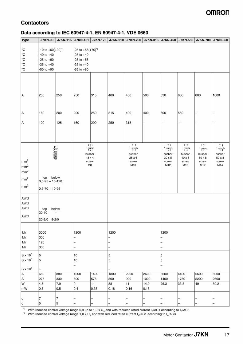
Contactors
Data according to IEC 60947-4-1, EN 60947-4-1, VDE 0660Type J7KN-90 J7KN-115 J7KN-151 J7KN-176 J7KN-210 J7KN-260 J7KN-316 J7KN-450 J7KN-550 J7KN-700 J7KN-860
°C -10 to +60(+90)*1
*1 With reduced control voltage range 0,9 up to 1,0 x Us and with reduced rated current Ie/AC1 according to Ie/AC3
-25 to +55(+70)*2
*2 With reduced control voltage range 1,0 x Us and with reduced rated current Ie/AC1 according to Ie/AC3
°C -40 to +40 -25 to +40
°C -25 to +60 -25 to +55
°C -25 to +40 -25 to +40
°C -50 to +90 -55 to +80
A 250 250 250 315 400 450 500 630 630 800 1000
A 160 200 200 250 315 400 400 500 560 – –
A 100 125 160 200 250 315 – – – – –
mm2
mm2
mm2
mm2 top below0,5-95 + 10-120
mm20,5-70 + 10-95
AWG
AWG
AWG top below20-10 –
AWG20-2/0 8-2/0
1/h 3000 1200 1200 1200
1/h 300 – – –
1/h 120 – – –
1/h 300 – – –
S x 106 5 10 5 5
S x 106 5 10 5 5
S x 106 ––
––
A 680 880 1200 1400 1800 2200 2600 3600 4400 5600 6900
A 275 330 500 575 800 900 1000 1400 1750 2200 2600
W 4,8 7,9 9 11 88 11 14,9 26,3 33,3 49 59,2
mW 0,6 0,5 0,4 0,35 0,18 0,16 0,15
g 7 7 – – – – – – – – –
g 5 5 – – – – – – – – –
busbar18 x 4screw
M8
busbar25 x 6screwM10
busbar30 x 5screwM12
busbar40 x 6screwM12
busbar50 x 8screwM12
busbar50 x 8screwM14

18 Motor Contactor J7KN
Contactors
Data according to IEC 60947-4-1, EN 60947-4-1, VDE 0660Auxiliary Contacts Type J7KN-10D/14D/18D/22D J7KNG-10/14/18/22 J7KN(G)-24/32/40 J7KN-50/62/74
Rated insulation voltage Ui *1
*1 Suitable for: earthed-neutral systems, overvoltage category I to IV, pollution degree 3 (standard-industry): Uimp = 8kV. Data for other conditions on request.
V~ 690 – –
Thermal rated current lth to 690V
Ambient temperature 40°C A 10 16 – –
60°C A 6 12 – –
Utilization category AC15Rated operational current le 220-240V A 3 12 – –
380-415V A 2 4 – –
440V A 1,6 4 – –
500V A 1,2 3 – –
660-690V A 0,6 1 – –
Utilization category DC13Rated operational current le 60V A 3,5 8 – –
110V A 0,5 1 – –
220V A 0,1 0,1 – –
Short circuit protectionShort-circuit current 1kA, contact welding not accepted
For contactors with thermal overload relay the device with the smaller admissible control fuse (contactor or thermal overload relay) determines the fuse.
max. fuse size gL (gG) A 25 – –
Control CircuitPower consumption of coilsAC operated inrush VA 33-45 90-115 140-165
sealed VA 7-10 9-13 13-18
W 2,6-3 2,7-4 5,4-7
DC operated inrush W 75 140 200
double winding coil sealed W 2 2 6
DC solenoid operated inrush W 3 4 –
(J7KNG) sealed W 3 4 –
Operation range of coilsin multiples of control voltage Us
AC operated 0,85-1,1 0,85-1,1 0,85-1,1
DC operated 0,8-1,1 0,8-1,1 0,8-1,1
Switching time at control voltage Us±10%*2,*3
*2 Total breaking time = release time + arc duration
AC operated make time ms 8-16 10-25 12-28
release time ms 5-13 8-15 8-15
arc duration ms 10-15 10-15 10-15
DC operated make time ms 8-12 10-20 12-23
release time ms 8-13 10-15 10-18
arc duration ms 10-15 10-15 10-15
DC solenoid operated make time ms 65-85 65-85 –
(J7KNG) release time ms 20-30 *4 20-30 *4 –
arc duration ms 10-15 10-15 –
Cable cross-sectionAuxiliary connector solid mm2 0,75-6 – –
flexible mm2 1-4 – –
flexible with multicore cable end mm2 0,75-4 – –
Magnet coil solid mm2 0,75-2,5 0,75-2,5 0,75-2,5
flexible mm2 0,5-2,5 0,5-2,5 0,5-2,5
flexible with multicore end mm2 0,5-1,5 0,5-1,5 0,5-1,5
Clamps per pole 2 2 2
Auxiliary connector solid AWG 18-10 – –
flexible AWG 18-10 – –
Magnet coil solid AWG 14-12 14-12 14-12
flexible AWG 18-12 18-12 18-12
Clamps per pole 2 2 2
Motor Contactor J7KN 19
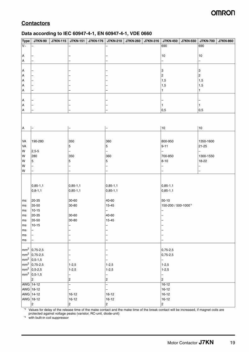
Contactors
Data according to IEC 60947-4-1, EN 60947-4-1, VDE 0660
*3 Values for delay of the release time of the make contact and the make time of the break contact will be increased, if magnet coils are protected against voltage peaks (varistor, RC-unit, diode-unit)
*4 with built-in coil suppressor
Type J7KN-90 J7KN-115 J7KN-151 J7KN-176 J7KN-210 J7KN-260 J7KN-316 J7KN-450 J7KN-550 J7KN-700 J7KN-860V~ – – – 690 690
A – – – 10 10
A – – – – –
A – – – 3 3
A – – – 2 2
A – – – 1,5 1,5
A – – – 1,5 1,5
A – – – 1 1
A – – – – –
A – – – 1 1
A – – – 0,5 0,5
A – – – 10 10
VA 190-280 350 360 800-950 1350-1600
VA 5 5 9-11 21-25
W 2,5-5 – – – –
W 280 350 360 700-850 1300-1550
W 5 5 5 8-10 18-22
W – – – – –
W – – – – –
0,85-1,1 0,85-1,1 0,85-1,1 0,85-1,1
0,8-1,1 0,85-1,1 0,85-1,1 0,85-1,1
ms 20-35 30-60 40-60 50-10
ms 35-50 30-80 15-45 150-200 / 500-1000*1
ms 10-15 – –
ms 20-35 30-60 40-60 –
ms 35-50 30-80 15-45 –
ms 10-15 – – –
ms – – – –
ms – – – –
ms – – – –
mm2 0,75-2,5 – – 0,75-2,5
mm2 0,75-2,5 – – 0,75-2,5
mm2 0,5-1,5 – – –
mm2 0,75-2,5 1-2,5 1-2,5 1-2,5
mm2 0,5-2,5 1-2,5 1-2,5 1-2,5
mm2 0,5-1,5 – – –
2 2 2 2
AWG 14-12 – – 16-12
AWG 18-12 – – 16-12
AWG 14-12 16-12 16-12 16-12
AWG 18-12 16-12 16-12 16-12
2 2 2 2
20 Motor Contactor J7KN
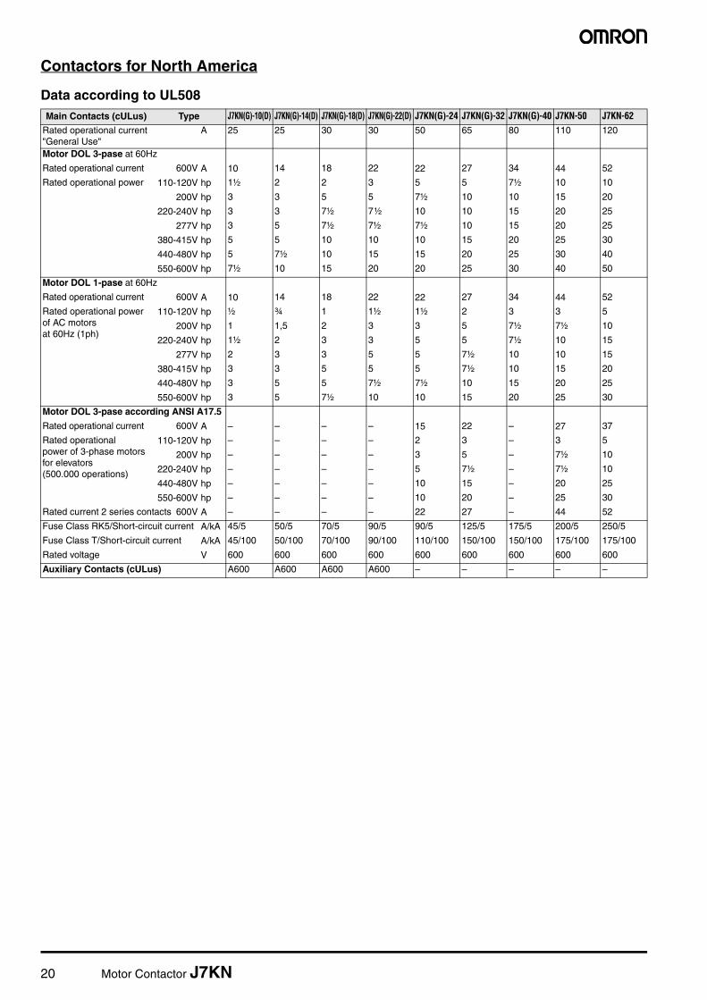
Contactors for North America
Data according to UL508Main Contacts (cULus) Type J7KN(G)-10(D) J7KN(G)-14(D) J7KN(G)-18(D) J7KN(G)-22(D) J7KN(G)-24 J7KN(G)-32 J7KN(G)-40 J7KN-50 J7KN-62
Rated operational current "General Use"
A 25 25 30 30 50 65 80 110 120
Motor DOL 3-pase at 60Hz
Rated operational current 600V A 10 14 18 22 22 27 34 44 52
Rated operational power 110-120V hp 1½ 2 2 3 5 5 7½ 10 10
200V hp 3 3 5 5 7½ 10 10 15 20
220-240V hp 3 3 7½ 7½ 10 10 15 20 25
277V hp 3 5 7½ 7½ 7½ 10 15 20 25
380-415V hp 5 5 10 10 10 15 20 25 30
440-480V hp 5 7½ 10 15 15 20 25 30 40
550-600V hp 7½ 10 15 20 20 25 30 40 50
Motor DOL 1-pase at 60Hz
Rated operational current 600V A 10 14 18 22 22 27 34 44 52
Rated operational powerof AC motorsat 60Hz (1ph)
110-120V hp ½ ¾ 1 1½ 1½ 2 3 3 5
200V hp 1 1,5 2 3 3 5 7½ 7½ 10
220-240V hp 1½ 2 3 3 5 5 7½ 10 15
277V hp 2 3 3 5 5 7½ 10 10 15
380-415V hp 3 3 5 5 5 7½ 10 15 20
440-480V hp 3 5 5 7½ 7½ 10 15 20 25
550-600V hp 3 5 7½ 10 10 15 20 25 30
Motor DOL 3-pase according ANSI A17.5
Rated operational current 600V A – – – – 15 22 – 27 37
Rated operational power of 3-phase motors for elevators (500.000 operations)
110-120V hp – – – – 2 3 – 3 5
200V hp – – – – 3 5 – 7½ 10
220-240V hp – – – – 5 7½ – 7½ 10
440-480V hp – – – – 10 15 – 20 25
550-600V hp – – – – 10 20 – 25 30
Rated current 2 series contacts 600V A – – – – 22 27 – 44 52
Fuse Class RK5/Short-circuit current A/kA 45/5 50/5 70/5 90/5 90/5 125/5 175/5 200/5 250/5
Fuse Class T/Short-circuit current A/kA 45/100 50/100 70/100 90/100 110/100 150/100 150/100 175/100 175/100
Rated voltage V 600 600 600 600 600 600 600 600 600
Auxiliary Contacts (cULus) A600 A600 A600 A600 – – – – –

Motor Contactor J7KN 21
Contactors for North America
Data according to UL508Type J7KN-74 J7KN-90 J7KN-115 J7KN-151 J7KN-176 J7KN-210 J7KN-260 J7KN-316 J7KN-450 J7KN-550 J7KN-700 J7KN-860A 130 160 200 180 220 250 300 350 420 520 700 810
A 66 85 99 125 150 300 400 550 700
hp 10 15 30 – – – – – – – – –
hp 25 25 35 40 50 60 75 100 125 150 200 250
hp 30 35 40 50 60 75 100 125 125 150 250 300
hp 30 – – – – – – – – – – –
hp 40 50 60 – – – – – – – – –
hp 50 65 75 100 125 150 200 250 250 350 500 600
hp 50 85 100 125 150 200 250 300 250 350 500 600
A 66 86 103 125 150 – – – – – – –
hp 7½ 8 10 15 25 – – – – – – –
hp 15 15 20 – – – – – – – – –
hp 15 20 25 25 30 40 50 50 – – – –
hp 15 20 25 – – – – – – – – –
hp 20 30 40 – – – – – – – – –
hp 25 40 50 – – – – – – – – –
hp 30 50 60 – – – – – – – – –
A – – – – – – – – – – – –
hp – – – – – – – – – – – –
hp – – – – – – – – – – – –
hp – – – – – – – – – – – –
hp – – – – – – – – – – – –
hp – – – – – – – – – – – –
A 66 – – – – – – – – – – –
A/kA 300/5 300/10 300/10 300/10 350/10 400/18 500/18 500/18 1200/18 1200/18 2000/30 2000/30
A/kA 175/100 300/100*1
*1 Class T and Class RK1
300/100*1 – – – – – – – – –
V 600 600 600 600 600 600 600 600 600 600 600
– – – – – – – – A600 A600 A600 A600

22 Motor Contactor J7KN
Contactors
Data according to IEC 60947-4-1, EN 60947-4-1, VDE 0660Contact Life
For selection of the suitable contactor-type according to supply volt-age, power rating and application (utilization category AC1, AC3 or AC4) use contact life characteristic diagram.
For the most common supply voltages four scales of power ratings Pn are provided for each utilization category.
Select contactor-type according to utilization category AC3 (breaking current Ia = Ie) using the motor rating scales to the right, according to utilization category AC4 (breaking current Ia = 6 x Ie) using the motor rating scales to the left.*1
Select contactor-type according to utilization category AC1 (breaking current Ia = Ie/AC1) using the breaking current scale.*1
For contactors frequently used under AC3/AC4-mixed service condi-tions calculate contact life with the formula:
1. Pay attention to the approved rated values of the selectedcontactor according to the national approvals
MAC3
1%AC4
100-----------------x
AC3AC4----------- 1– +
---------------------------------------------------------=
M = Contact life (switching cycles) for AC3/AC4-mixed operations
AC3 = Contact life (switching cycles) for AC3 operations (normal switching conditions). Breaking current Ia = rated motor current In.
AC4 = Contact life (switching cycles) for AC4 operations (inching).
Breaking current Ia= multiples of rated motor current In.
%AC4 = Percents of AC4-operations related to the total cycles.
A
Motor RatingPn/AC4
Motor RatingPn/AC3
Breaking CurrentIa (=Ie/AC1)
J7KN-74
J7KN-24
J7KN-32J7KN-40
J7KN-50J7KN-62
J7KN-22J7KN-18J7KN-14J7KNA-12J7KN-10J7KNA-09
millions of operations
J7KN-860J7KN-700
J7KN-550J7KN-450J7KN-316J7KN-260J7KN-210J7KN-176J7KN-151
J7KN-115
J7KN-90
A
Motor RatingPn/AC4
Motor RatingPn/AC3
Breaking CurrentIa (=Ie/AC1)
millions of operations
100008000
6000
4000
2000
1000800
600
400
200
10080
60
40
20
100,01 0,02 0,04 0,06 0,08 0,1 0,2 0,4 0,6 0,8 1 2 4 6 8 10
Motor Contactor J7KN 23
Contactors
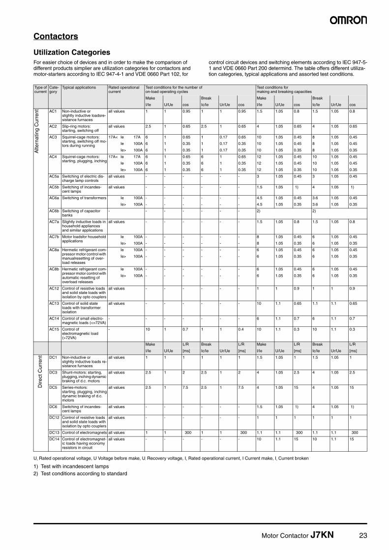
Utilization CategoriesFor easier choice of devices and in order to make the comparison of different products simplier are utilization categories for contactors and motor-starters according to IEC 947-4-1 and VDE 0660 Part 102, for
control circuit devices and switching elements according to IEC 947-5-1 and VDE 0660 Part 200 determind. The table offers different utiliza-tion categories, typical applications and assorted test conditions.
Ue Rated operational voltage, U Voltage before make, Ur Recovery voltage, Ie Rated operational current, I Current make, Ic Current broken
1) Test with incandescent lamps2) Test conditions according to standard
Type of current
Cate-gory
Typical applications Rated operational current
Test conditions for the number ofon-load operating cycles
Test conditions for making and breaking capacities
Make Break Make Break
I/Ie U/Ue cos Ic/Ie Ur/Ue cos I/Ie U/Ue cos Ic/Ie Ur/Ue cos
Alte
rnat
ing
Cur
rent AC1 Non-inductive or
slightly inductive loadsre-sistance furnaces
all values 1 1 0.95 1 1 0.95 1.5 1.05 0.8 1.5 1.05 0.8
AC2 Slip-ring motors:starting, switching off
all values 2.5 1 0.65 2.5 1 0.65 4 1.05 0.65 4 1.05 0.65
AC3 Squirrel-cage motors: starting, switching off mo-tors during running
17A< Ie 17A 6 1 0.65 1 0.17 0.65 10 1.05 0.45 8 1.05 0.45
Ie 100A 6 1 0.35 1 0.17 0.35 10 1.05 0.45 8 1.05 0.45
Ie> 100A 6 1 0.35 1 0.17 0.35 10 1.05 0.35 8 1.05 0.35
AC4 Squirrel-cage motors:starting, plugging, inching
17A< Ie 17A 6 1 0.65 6 1 0.65 12 1.05 0.45 10 1.05 0.45
Ie 100A 6 1 0.35 6 1 0.35 12 1.05 0.45 10 1.05 0.45
Ie> 100A 6 1 0.35 6 1 0.35 12 1.05 0.35 10 1.05 0.35
AC5a Switching of electric dis-charge lamp controls
all values - - - - - - 3 1.05 0.45 3 1.05 0.45
AC5b Switching of incandes-cent lamps
all values - - - - - - 1.5 1.05 1) 4 1.05 1)
AC6a Switching of transformers Ie 100A - - - - - - 4.5 1.05 0.45 3.6 1.05 0.45
Ie> 100A - - - - - - 4.5 1.05 0.35 3.6 1.05 0.35
AC6b Switching of capacitor banks
- - - - - - - 2) 2)
AC7a Slightly inductive loads in household appliances and similar applications
all values - - - - - - 1.5 1.05 0.8 1.5 1.05 0.8
AC7b Motor loadsfor household applications
Ie 100A - - - - - - 8 1.05 0.45 6 1.05 0.45
Ie> 100A - - - - - - 8 1.05 0.35 6 1.05 0.35
AC8a Hermetic refrigerant com-pressor motor control with manualresetting of over-load releases
Ie 100A - - - - - - 6 1.05 0.45 6 1.05 0.45
Ie> 100A - - - - - - 6 1.05 0.35 6 1.05 0.35
AC8b Hermetic refrigerant com-pressor motor control with automatic resetting of overload releases
Ie 100A - - - - - - 6 1.05 0.45 6 1.05 0.45
Ie> 100A - - - - - - 6 1.05 0.35 6 1.05 0.35
AC12 Control of resistive loads and solid state loads with isolation by opto couplers
all values - - - - - - 1 1 0.9 1 1 0.9
AC13 Control of solid state loads with transformer isolation
all values - - - - - - 10 1.1 0.65 1.1 1.1 0.65
AC14 Control of small electro-magnetic loads (<=72VA)
- - - - - - - 6 1.1 0.7 6 1.1 0.7
AC15 Control ofelectromagnetic load (>72VA)
- 10 1 0.7 1 1 0.4 10 1.1 0.3 10 1.1 0.3
Make L/R Break L/R Make L/R Break L/R
I/Ie U/Ue [ms] Ic/Ie Ur/Ue [ms] I/Ie U/Ue [ms] Ic/Ie Ur/Ue [ms]
Dire
ct C
urre
nt DC1 Non-inductive orslightly inductive loads re-sistance furnaces
all values 1 1 1 1 1 1 1.5 1.05 1 1.5 1.05 1
DC3 Shunt-motors: starting, plugging, inching dynamic braking of d.c. motors
all values 2.5 1 2 2.5 1 2 4 1.05 2.5 4 1.05 2.5
DC5 Series-motors:starting, plugging, inchingdynamic braking of d.c. motors
all values 2.5 1 7.5 2.5 1 7.5 4 1.05 15 4 1.05 15
DC6 Switching of incandes-cent lamps
all values - - - - - - 1.5 1.05 1) 4 1.05 1)
DC12 Control of resistive loads and solid state loads with isolation by opto couplers
all values - - - - - - 1 1 1 1 1 1
DC13 Control of electromagnets all values 1 1 300 1 1 300 1.1 1.1 300 1.1 1.1 300
DC14 Control of electromagnet-ic loads having economy resistors in circuit
all values - - - - - - 10 1.1 15 10 1.1 15

24 Motor Contactor J7KN
Accessories
Data according to IEC 60947-4-1, EN 60947-5-1, VDE 0660
Data according to CSA, UL and CUL
Auxiliary Contacts Type J73KN-B J73KN-B...A J73KN-C J73KN-D J74KN-B-TP...
Rated insulation voltage Ui*1
*1 Suitable for: earthed-neutral systems, overvoltage category I to IV, pollution degree 3 (standard-industry): Uimp = 8kV. Data for other conditions on request
V~ 690 690 690 690 690
Thermal rated current Ith to 690V
Ambient temperature 40°C A 10 25 10 10 10
60°C A 6 20 6 -
Frequency of operations z 1/h 3000 3000 3000 3000 1200
Mechanical life S x 106 10 10 10 10 1
Power loss per pole at Ie/AC1 W 0,5 1,5 0,5 - -
Utilization category AC15
Rated operational current Ie 220-240V A 3 6 3 3 4
380-400V A 2 3 2 2 3
440V A 1,6 2 1,6 1,5 2
500V A 1,2 2 1,2 1,5 2
660-690V A 0,6 1 0,6 1 2
Utilization category DC13
Rated operational current Ie 60V A 2 8 2 - 2,5
110V A 0,4 1 0,4 1 1,5
220V A 0,1 0,1 0,1 0,5 0,2
Short circuit protection
short-circuit current 1kA, contact welding not accepted max. fuse size
gL (gG) A 20 25 20 10 10
For contactors with thermal overload relay or auxiliary con-tacts the device with the smaller admissible control fuse (contactor or thermal overload relay) determines the fuse size.
Cable cross-sections
solid or stranded mm² 0,75-2,5 0,75-2,5 0,75-2,5 0,75-2,5 1-2,5
flexible mm² 0,75-2,5 0,75-2,5 0,75-2,5 0,75-2,5 0,75-2,5
flexible with multicore cable end mm² 0,5-1,5 0,5-1,5 0,5-1,5 - 0,75-2,5
Cables per clamp 2 2 2 2 2
Auxiliary Contacts Type J73KN-B J73KN-B...A J73KN-C J73KN-D J74KN-B-TP...
Rated operational current„General Use“
A 10 16 10 10 10
Rated operational voltage max. V AC 600 600 600 600 600
Auxiliary Contacts A600 A600 A600 A600 A600

Motor Contactor J7KN 25
■ Dimensions / Position of Terminals
ContactorsJ7KN-10D/14D/18D/22D(-4)... J7KN-10D-10 to
J7KN-22D-10J7KN-10D-01 to J7KN-22D-01
J7KN-10D-4_ to J7KN-22D-4_
J7KNG-10/14/18/22(-4)...D J7KNG-10-10...DJ7KNG-14-10...DJ7KNG-18-10...DJ7KNG-22-10...D
J7KNG-10-01...DJ7KNG-14-01...DJ7KNG-18-01...DJ7KNG-22-01...D
J7KNG-10-4_...DJ7KNG-14-4_...DJ7KNG-18-4_...DJ7KNG-22-4_...D
J7KN-10D/14D/18D/22D...D J7KN-10D-10...DJ7KN-14D-10...DJ7KN-18D-10...DJ7KN-22D-10...D
J7KN-10D-01...DJ7KN-14D-01...DJ7KN-18D-01...DJ7KN-22D-01...D
J7KN-10D-4_...DJ7KN-14D-4_...DJ7KN-18D-4_...DJ7KN-22D-4_...D
J7KN-24/32/40... J7KN-24J7KN-32J7KN-40
J7KNG-24/32/40...D J7KNG-24...DJ7KNG-32...DJ7KNG-40...D
45
35
89 80
111
107
6.5
79
M3.5
Ø4.5
94
45
35
65 60
104.5
100.5
74
6.5
63
M5
1010
Ø4,5
87.5
125121
6.586
M5
›4.5
8089
3545 1010
108
1 L1 3 L2 5 L3
A2A1
4 T22 T1 6 T3
A1 A2
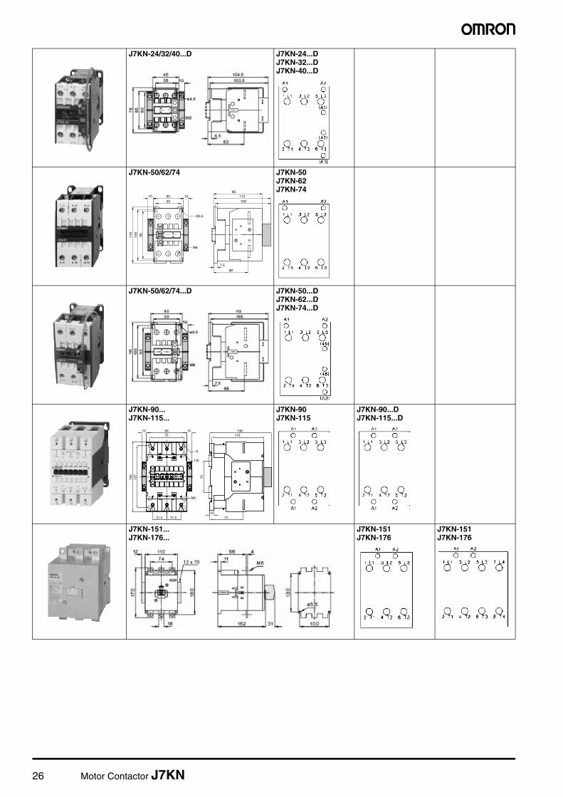
26 Motor Contactor J7KN
J7KN-24/32/40...D J7KN-24...DJ7KN-32...DJ7KN-40...D
J7KN-50/62/74 J7KN-50J7KN-62J7KN-74
J7KN-50/62/74...D J7KN-50...DJ7KN-62...DJ7KN-74...D
J7KN-90...J7KN-115...
J7KN-90J7KN-115
J7KN-90...DJ7KN-115...D
J7KN-151...J7KN-176...
J7KN-151J7KN-176
J7KN-151J7KN-176
60
50
100
95
113
109
110
7.5
68
M6
10 10
Ø5.5
96
75
137
70
90
(›6)
155
31.531.59
74
M8
136115
›6
1010
12 x 70
Motor Contactor J7KN 27
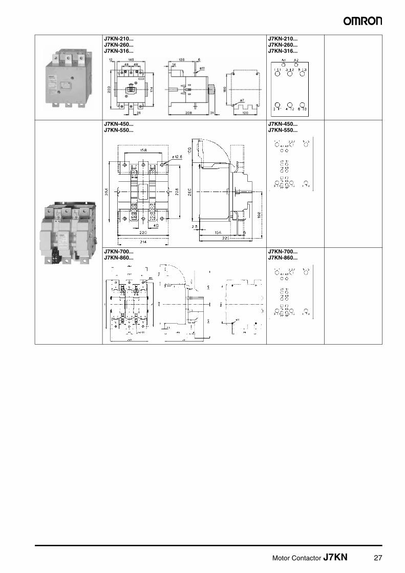
J7KN-210... J7KN-260... J7KN-316...
J7KN-210... J7KN-260... J7KN-316...
J7KN-450... J7KN-550...
J7KN-450... J7KN-550...
J7KN-700... J7KN-860...
J7KN-700... J7KN-860...

28 Motor Contactor J7KN
Auxiliary contacts blocks
Pneumatic Timer
Mechanical Interlocks
Suppressor Units
J74KN-B J74KN-C J74KN-D_F J74KN-D_S J74KN-F
J74KN-B-TP...
J74KN-B-ML J74KN-C-ML J74KN-D2-ML J74KN-E-ML
J74KN-C2-RC
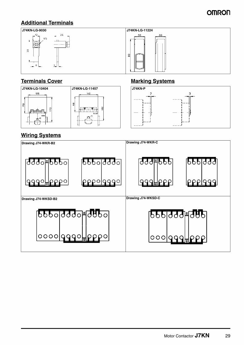
Motor Contactor J7KN 29
Additional Terminals
Terminals Cover Marking Systems
Wiring Systems
J74KN-LG-9030 J74KN-LG-11224
J74KN-LG-10404 J74KN-LG-11457 J74KN-P
Drawing J74-WKR-B2 Drawing J74-WKR-C
Drawing J74-WKSD-B2 Drawing J74-WKSD-C
30 Motor Contactor J7KN
In the interest of product improvement, specifications are subject to change without notice.
ALL DIMENSIONS SHOWN ARE IN MILLIMETERS.
Cat. No. J06E-EN-04A
Do not use/install these products before having read the applicable precautions as listed in Cat. No. J09-EN-01available from www.europe.omron.com or on request from OMRON local sales office.