motm-300 user manual
TRANSCRIPT
MOTM-300 Voltage-Controlled Oscillator Assembly Instructions & Owner’s Manual
Synthesis Technology 6625 Quail Ridge Dr.
Fort Worth, TX 76180 (817) 498-3782
www.synthtech.com
July 25, 1999
SYNTHESIS TECHNOLOGY PAGE 2 MOTM-300 ASSEMBLY 7/25/99 WWW.SYNTHTECH.COM
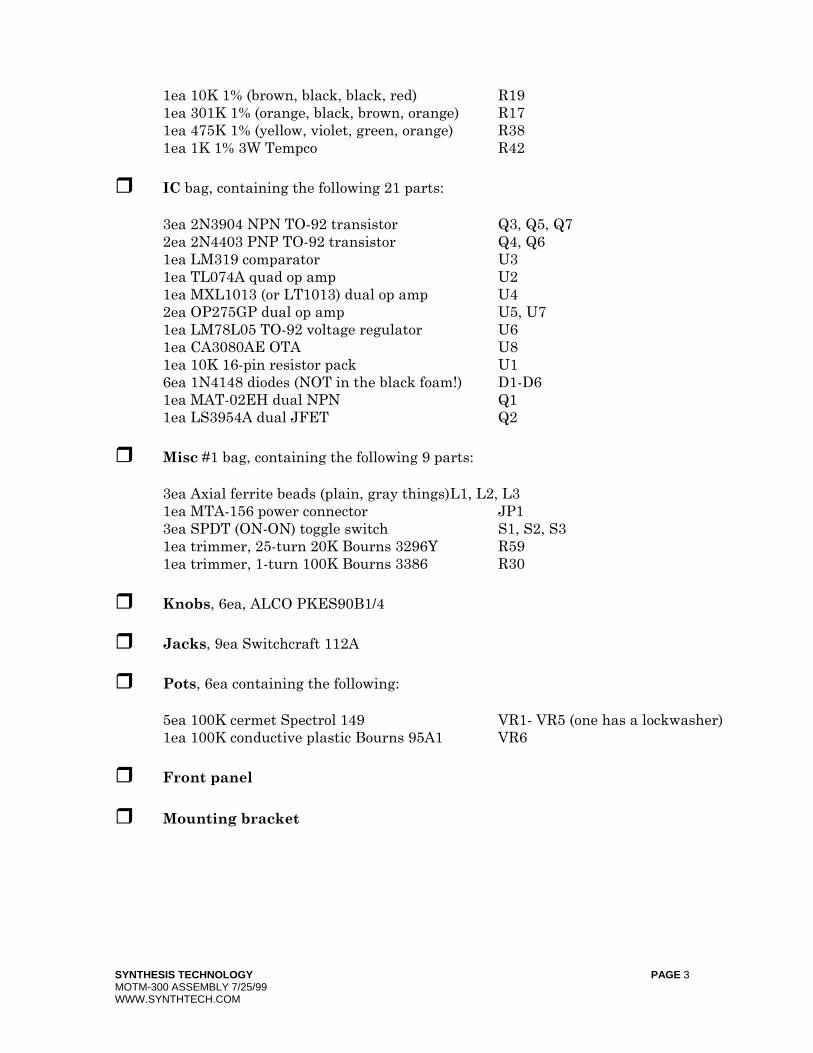
MOTM-300 PARTS LIST Please carefully check that all parts are in your kit. If you have a suspected shortage, please call or email. If you get free extra stuff, keep it for next time.
Capacitor bag, containing the following 26 parts: 3ea 10mfd, 25V or 50V Electrolytic C5, C16, C17 6ea 100pf (marked 101) ceramic axial C4, C9, C14, C23, C24, C26 1ea 220pf (marked 221) ceramic axial C3 2ea 22pf (marked 220) ceramic axial C2, C13 1ea 4700pf axial polystyrene C15 13ea 0.1mfd (marked 104) ceramic axial C1, C6-8, C10-12, C18-22, C25
5% Resistor bag, containing the following 40 parts: 7ea 10K (brown, black, orange) R2, R5, R10, R20, R21, R33, R60 6ea 1K (brown, black, red) R9, R24, R31, R34, R44, R54 4ea 47K (yellow, violet, orange) R12, R15, R40, R46 3ea 4K7 (yellow, violet, red) R25, R41, R100 (R100 off-board!) 3ea 100K (brown, black, yellow) R1, R13, R22 2ea 43K (yellow, orange, orange) R51, R53 2ea 2M2 (red, red, green) R39, R50
2ea 1M (brown, black, green) R6, R35 2ea 1K5 (brown, green, red) R7, R32 1ea 3K9 (orange, white, red) R8 1ea 470K (yellow, violet, yellow) R11 1ea 330K (orange, orange, yellow) R14 1ea 75K (violet, green, orange) R16 1ea 300 Ω (orange, black, brown) R23 1ea 22Ω (red, red, black) R28 1ea 62K (blue, red, orange) R43 1ea 22K (red, red, orange) R49 1ea 220K (red, red, yellow) R52
Precision Resistor bag, containing the following 19 parts:
4ea 1K50 1% (brown, green, black, brown) R26, R27, R29, R36 3ea 100K 1% (brown, black, black, orange) R18, R57, R58 2ea 51K1 1% (green, brown, brown, red) R47, R48
1ea 100K 0.1% (marked 1003B) R45 1ea 3M32 1% (marked with value) R3 1ea 1M 1% (marked with 1004F) R37 1ea 150K 0.1% (marked 1503B) R4 1ea 69K8 1% (marked 6982F) R55 1ea 44K2 1% (marked 4422F) R56
SYNTHESIS TECHNOLOGY PAGE 3 MOTM-300 ASSEMBLY 7/25/99 WWW.SYNTHTECH.COM
1ea 10K 1% (brown, black, black, red) R19 1ea 301K 1% (orange, black, brown, orange) R17 1ea 475K 1% (yellow, violet, green, orange) R38 1ea 1K 1% 3W Tempco R42
IC bag, containing the following 21 parts: 3ea 2N3904 NPN TO-92 transistor Q3, Q5, Q7 2ea 2N4403 PNP TO-92 transistor Q4, Q6 1ea LM319 comparator U3 1ea TL074A quad op amp U2 1ea MXL1013 (or LT1013) dual op amp U4 2ea OP275GP dual op amp U5, U7 1ea LM78L05 TO-92 voltage regulator U6 1ea CA3080AE OTA U8 1ea 10K 16-pin resistor pack U1 6ea 1N4148 diodes (NOT in the black foam!) D1-D6 1ea MAT-02EH dual NPN Q1 1ea LS3954A dual JFET Q2
Misc #1 bag, containing the following 9 parts: 3ea Axial ferrite beads (plain, gray things) L1, L2, L3 1ea MTA-156 power connector JP1 3ea SPDT (ON-ON) toggle switch S1, S2, S3 1ea trimmer, 25-turn 20K Bourns 3296Y R59 1ea trimmer, 1-turn 100K Bourns 3386 R30
Knobs, 6ea, ALCO PKES90B1/4
Jacks, 9ea Switchcraft 112A
Pots, 6ea containing the following: 5ea 100K cermet Spectrol 149 VR1- VR5 (one has a lockwasher) 1ea 100K conductive plastic Bourns 95A1 VR6
Front panel
Mounting bracket
SYNTHESIS TECHNOLOGY PAGE 4 MOTM-300 ASSEMBLY 7/25/99 WWW.SYNTHTECH.COM
Wire bag, containing the following 15 wires: 4ea RG-174 coax, 4 ½ inches 1ea RG-174 coax, 7 inches 4ea 3-wire set 22ga, 4 ½ inches (white/orange/gray) 2ea 2-wire set, 22ga, 7 inches (white/orange) 3ea 2-wire set, 22ga, 3 ½ inches (red/black) 1ea Power Cable, 20”
Hardware bag, containing: 4ea #8-32 x 3/8 black screws (for mounting module to rack) 4ea #6-32 x 1/2 zinc screws (for attaching pc board to bracket) 4ea 1/4 inch aluminum spacers 6ea #6 KEPS nuts (2 for attaching bracket to front panel, 4 for pc board) 8ea small tie-wraps 3ea small heat-shrink tubing
Organic Solder
No-clean Solder
PC Board, MOTM-300

SYNTHESIS TECHNOLOGY PAGE 5 MOTM-300 ASSEMBLY 7/25/99 WWW.SYNTHTECH.COM
GENERAL INFORMATION Thank you for purchasing the MOTM-300 Ultra Voltage-Controlled Oscillator (VCO). If you have any issues concerning the building or use of the kit, please contact us at (888) 818-MOTM [6686] or by email: [email protected]. This kit should take the average builder between 4 to 5 hours. The VCO kit contains many different resistors and special parts that require very accurate soldering skills. However, please remember this is NOT a speed contest; it is an accuracy contest. There is no rule that you have to complete the entire kit in one day (as long as you wash the flux off!). Successful kit building relies on having the proper tools. Here is a list of what you will need to build your MOTM-300: * Soldering iron, 50W max power * A heat-shrink gun. (optional, but highly recommended) * Needle-nose or chain-nose pliers * Diagonal cutters * Allen key set for securing the knobs (1/16” or 1.58mm) * Magnifying glass: to read the capacitor codes and to inspect solder joints * Lead bending tool (optional, but makes the job go much faster) * DVM (Digital Volt Meter) or oscilloscope (to check the output) * #1 Philips screwdriver * Small, flat screwdriver for adjusting the trimmers * Fingernail brush for washing off the organic flux * Old towel for blotting dry pc board * Heat-sink compound: this is REQUIRED for proper VCO operation. Available from
Allied, Newark, Mouser, Radio Shack, Farnell, and most all electronic supply companies. (Postal regulations force me not to include with the kit!)
For more information of tools used and suggestions, see the MOTM FAQ and Tutorial pages at http://www.synthtech.com. You also may find it useful to purchase additional heat-shrink tubing and solder. Just be sure it is NOT rosin-based flux! HOW TO FOLLOW THE DIRECTIONS Please read the entire instruction before proceeding. There may be valuable information at
the end of the instruction. Each instruction has a check box next to it. After you complete the instruction, check the box. This way you can keep track of where you are in the process. VERY IMPORTANT – PLEASE READ! This kit is unlike any other MOTM kit! It is critical that you follow the steps exactly in order for proper operation. This kit contains expensive, hard-to-find parts! Please read ALL of an instruction before proceeding.

SYNTHESIS TECHNOLOGY PAGE 6 MOTM-300 ASSEMBLY 7/25/99 WWW.SYNTHTECH.COM
VERIFY THE PARTS LIST
Verify that all of the parts are in the kit as shown on the parts list. A WORD ON SOLDERING There are 2 very different types of solder used in the kit. Most of the soldering uses ‘Organic Flux’ solder. This is strictly for use on the pc board, and is NOT to be used on the front panel wiring! In order for solder to ‘stick’ to the copper, a chemical called ‘flux’ is embedded in the solder. The flux leaves a residue on the pc board that should be cleaned with warm water. DO NOT USE SOAP OR OTHER CLEANSERS. Most of the parts in the kits are ‘waterproof’ and can be washed in the sink. The flux is OSHA approved for flushing down the drain, so don’t worry about that! A soft brush is used to gently scrub the board. We recommend a ‘fingernail brush’, which is about 1” x 2” and can be found for about $1. The other type of solder is called ‘No Clean Flux’; because as the name implies it does, not require washing. This solder is used for wiring the pots, switches, jacks, etc. This solder is harder to use on the pc board; because even when melted, it is not very fluid (about the consistency of toothpaste). We will use it VERY SPARINGLY on the pc board. OK, let’s get started on the board! PART #1: SOLDERING THE RESISTORS Since there are more resistors than anything else, we will start here. If you do not know the resistor color code, refer to the parts list. Resistors are not polarity sensitive, but the board will be easier to debug (and look nicer) if you point the first color band in the same direction for all the parts. The color code is also in the README FIRST document that every customer receives with his or her first order. There are 2 types of resistors in the MOTM-300 kit: standard 5%, 1/4W parts and special, precision parts. The precision parts use a slightly different color-coding scheme or have the part value stamped on the resistor which is a coding scheme similar to the ceramic capacitors. If you are unsure of a resistor’s value, use your trusty DVM to measure it! Inserting the wrong resistor in the VCO kit will cause interesting behavior! And, it’s very hard to find the error! You will start by soldering in ALL of the 5% resistors.
Find the 5% RESISTOR bag.
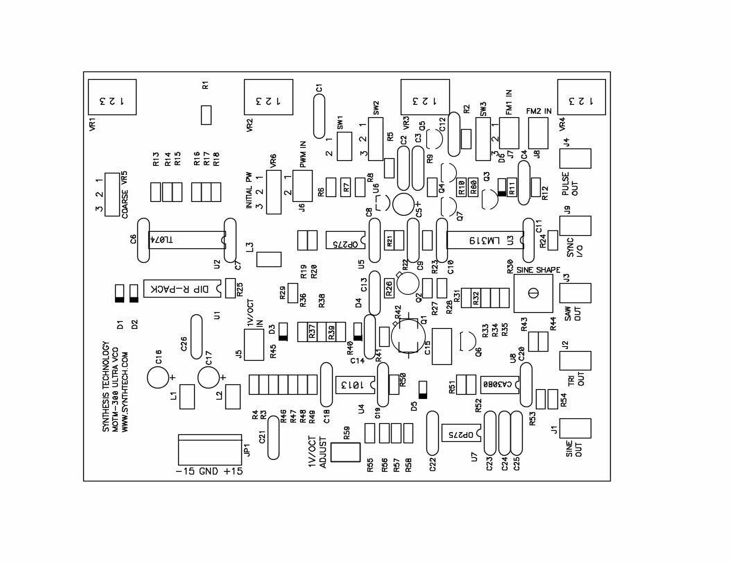
Find the MOTM-300 blank pc board. There is a copy (larger than actual size) of the silkscreen which shows where the parts go at the end of this document. It will be useful if you locate the part on the print first, put the part in the board, then ‘check off’ the silkscreen. All parts are inserted from the side of the board with the white silkscreen (the “top” side).
SYNTHESIS TECHNOLOGY PAGE 7 MOTM-300 ASSEMBLY 7/25/99 WWW.SYNTHTECH.COM
We will stuff the resistors by value to make things easier. The resistors (and other long-leaded parts) are inserted on a 0.4 inch spacing. The important thing is to be sure that the part is sitting all the way down on the board. Push the leads in the holes, push the part on the board, and then bend the leads on the bottom outwards to a 45 degree angle (roughly!). This is called ‘cinching the leads’: and keeps the part from falling out! From the bottom of the board, solder (using the organic flux), applying heat to the pad for about a half second first, then applying just enough solder to make a small puddle that looks like a tiny pyramid. Enough solder should flow in the hole such that on the top (component) side, a small amount is on the top pad as well
The rule of soldering: don’t use too much, you can always add more! Cut the leads flush with the top of the solder joint with your diagonal cutters. This pc board has parts very close together. It may not be clear where a certain resistor or capacitor is. We will try to give you a “hint” for the hard-to-find parts!
Also note, that due to the tight spacing, some of the actual printed silkscreen may be missing on the pc board. Please refer to the printout if you question a part location.
NOTE: you will need to save 3 of the resistor leads after you cut them! Don’t forget!
Locate the 100K resistors (3) and solder into R1 (near R17), R13, and R22 (above C9).
Locate the 10K resistors (7) and solder into R2 (above SW3), R5 (above C2), R10, R20, R21 (below C8), R33, and R60 (below R10).
Locate the 1M resistors (2) and solder into R6 and R35.
Locate the 1K5 (1.5K) resistors (2) and solder into R7 and R32 (Note the ‘2’ is missing on the pc board because the pad got in the way! It’s right beside Q6: see the silkscreen printout).
Locate the 3K9 (3.9K) resistor and solder into R8.
Locate the 1K resistors (6) and solder into R9 (by Q4), R24 (by J9), R31, R34, R44, and R54 (by J1).
Locate the 470K resistor and solder into R11 (above C4).
Locate the 47K resistors (4) and solder into R12, R15, R40 (above D4), and R46 (by C21).
SYNTHESIS TECHNOLOGY PAGE 8 MOTM-300 ASSEMBLY 7/25/99 WWW.SYNTHTECH.COM
Locate the 330K resistor and solder into R14. PART #2: BOARD WASH #1
Verify all the resistors are in the correct position.
Verify all the resistors are flat on the board. Correct if needed. Check solder joints.
Wash the board in warm water, gently scrubbing both sides.
Shake the board a couple of times, blot dry with an old towel (the leads will frazzle a good towel). Let dry about 15 minutes. PART #3: Complete the 5% Resistors
Locate the 75K resistor and solder into R16.
Locate the 300Ω resistor and solder into R23 (in between C9 and C10).
Locate the 4K7 (4.7K) resistors (2) and solder into R25 (next to U1) and R41 (above Q1). There will be 1 4K7 resistor left! DO NOT LOSE THIS!
Locate the 22Ω resistor and solder into R28 (right above R31).
Locate the 2ea 2M2 (2.2M) resistors and solder into R39 and R50.
Locate the 62K resistor and solder into R43
Locate the 22K resistor and solder into R49.
Locate the 43K resistors (2) and solder into R51 and R53.
Locate the 220K resistor and solder into R52.
This completes the 5% resistors. Check your solder joints and wash the board again! Let dry 15 minutes. Take a little break!
SYNTHESIS TECHNOLOGY PAGE 9 MOTM-300 ASSEMBLY 7/25/99 WWW.SYNTHTECH.COM
PART #4: Precision Resistors EXCEPT R42 IMPORTANT NOTE! R42 is the last part soldered on the board! DO NOT SOLDER this part until told so. You have been warned! In order to make debugging the board easier later on, be sure that you install the resistors which have printed values on them with the value facing up where you can read it!
Locate the 100K, 0.1% resistor and solder into R45.
Locate the 3M32 (3.32M) resistor and solder into R3.
Locate the 1M 1% resistor and solder into R37 (the ‘7’ is missing!)
Locate the 150K 0.1% resistor and solder into R4.
Locate the 69K8 (69.8K) 1% resistor and solder into R55.
Locate the 44K2 (44.2K) 1% resistor and solder into R56.
Locate the 51K1 (51.1K) 1% resistors (2) and solder into R47 and R48.
Locate the 10K 1% resistor and solder into R19.
Locate the 301K 1% resistor and solder into R17.
Locate the 1K5 (1.5K) 1% resistors (4) and solder into R26 (below C13, and note some of the ‘26’ is missing), R27, R29 (by D3), and R36.
Locate the 100K 1% resistors (3) and solder into R18, R57, and R58.
Locate the 475K 1% resistor and solder into R38.
STOP! Save the big black tempco resistor for later. DON’T LOSE IT! PART #5: BOARD WASH #3
Verify all the resistors are in the correct position.
Verify all the resistors are flat on the board. Correct if needed. Check solder joints.
Wash the board in warm water, gently scrubbing both sides.
SYNTHESIS TECHNOLOGY PAGE 10 MOTM-300 ASSEMBLY 7/25/99 WWW.SYNTHTECH.COM
Shake the board a couple of times and blot dry. Take another break or set the kit aside for later. You are about one-third finished at this point.
PART #6: CAPACITORS EXCEPT C15
Locate the CAPACITOR bag. Set the polystyrene 4700pf cap (the big silvery one with the long, thin leads) aside. THIS CAP IS SOLDERED IN AFTER THE ICs!
Locate the 100pf ceramic axial caps (6). They are marked 101. Solder into C4 (between R11 & R12), C9, C14 (below D4), C23, C24, and C26 (up there by U1, part of the “26” is missing).
Locate the 220pf cap and solder into C3 (beside Q5).
Locate the 22pf caps (2) and solder into C2 and C13 (above R26).
Locate the 0.1M caps (13). Solder into C1, C6, C7, C8, C10, C11, C12, C18, C19, C20, C21, C22, and C25. These should be easy to find: they are all the caps left except for the 3 electrolytics!
Locate the 10µfd electrolytics (3). Note that there is a stripe on the NEGATIVE terminal. The pc board has a + on the POSITIVE terminal. Carefully stick the
capacitors into C5, C16, and C17 with the stripe away from the + pad on the board.
Wash the board again, gently scrubbing both sides. Use ONLY warm water! PART #7: MISC and IC STUFF Almost done with the parts on the pc board! This will finish up the soldering with the organic flux.
Locate the MISC #1 bag and the IC bag.
Locate the ferrite beads (3). They are axial parts, gray colored with no markings. These are non-polar, and are soldered into L1, L2, and L3 (below C7).
Locate the MTA-156 power connector. Solder into JP1. Note that the connector has a ‘locking tab’ on one side. This side is the “inside” facing relative to the pc board. Note the silkscreen symbol for JP1 has a line on one side, indicating this is the side where the locking tab goes. Locate the LM319 comparator. Solder into U3. Note that Pin #1 is the
square pad. Pin #1 is the pin near the very small ‘dimple’ in the top of the part. All of the ICs point “to the bottom” on the pc board.

SYNTHESIS TECHNOLOGY PAGE 11 MOTM-300 ASSEMBLY 7/25/99 WWW.SYNTHTECH.COM
Locate the TL074A. Solder into U2.
Locate the 10K DIP resistor pack. This part contains 8 10K resistors. A black dot indicates pin 1 which will go in the square pad. Solder into U1.
Locate the 1013 op amp. Solder into U4.
Locate the OP275GP op amps (2). Solder into U5 and U7.
Locate the CA3080AE. Solder into U8.
Locate the 2N3904 NPN transistors (3). Look closely, they are marked on the “flat side” of the part. DO NOT GET THESE CONFUSED WITH THE VOLTAGE REGULATOR! Insert the 3 leads, with the bottom of the part about 1/8” from
the pc board. DO NOT try to push the transistor all the way down on the board! Solder in Q3, Q5, and Q7. Note they all “face upwards”.
Locate the LM78L05. Look closely, it is marked on the “flat side” of the part. Note the hole pattern on the pc board has the middle lead slightly forward. Insert the 3 leads, with the bottom of the part about 1/8” from the pc board. DO NOT try to push the part all the way down on the board! Solder in U6.
Locate the 2N4403 transistors (2). Solder into Q4 and Q6.
Locate the diodes (6). Note each has a dark band on one end on the body. This is the cathode and it must be placed in the holes with the band pointing to the left. Solder into D1 – D6.
Locate the trimmer pot that is a flat square with a white adjustment screw. Solder into R30.
Locate the trimmer pot that has the small brass adjustment screw and solder into R59.
Wash the pc board again.
Locate the 4700pf polystyrene cap. Solder into C15.
The next 2 parts are the most difficult to insert and solder. BE VERY PATIENT AND TAKE YOUR TIME! THESE PARTS ARE EXPENSIVE TO REPLACE IF DAMAGED BY HANDLING OR IMPROPER SOLDERING!

SYNTHESIS TECHNOLOGY PAGE 12 MOTM-300 ASSEMBLY 7/25/99 WWW.SYNTHTECH.COM
Locate MAT-02EH transistor Q1. Note that it has a small ‘tab’ sticking out sideways from the can (see illustration). Also note that on the underside of the part is a ceramic spacer that is protruding slightly. Place the part carefully in the holes, so that the tab on the part is over the tab on the silkscreen (towards the upper right corner). Push the part gently down all the way on the pc board until it touches the board. Now solder the six leads. IT IS VERY IMPORTANT FOR PROPER OPERATION THAT THE MAT-02 BE ALL THE WAY FLAT AND LEVEL ON THE PC BOARD!
Locate the LS3954A dual JFET. It goes into Q2. Note that it looks like a smaller version of Q1. However DO NOT PUSH THIS PART DOWN ALL THE WAY ON THE BOARD! You will find that the leads must be carefully and gently be bent into position in order for the part to go into the 6 closely spaced holes. BE PATIENT! Again, look for the alignment tab on the part and solder Q2 in place (the tab points to the upper right). The 6 pads are VERY CLOSE TOGETHER AND VERY SMALL IN SIZE. Use a magnifying glass to examine your joints. BE VERY VERY CAREFUL THAT 2 ADJACENT PADS ARE NOT SHORTED BY SOLDER!
Being careful NOT to solder the 2 pads for R42, apply a small bit of solder to the via
holes. These are the small pads that allow traces to “change sides” of the pc board. DO NOT SOLDER PADS FOR THE REMAINING COMPONENTS!!
PART #8: FINAL BOARD WASH & INSPECTION
Verify all the parts are in the correct locations. Make sure all of the ICs are pointing the same direction and that all of the diodes point to the left.
Inspect the solder joints. Any solder shorts? Too much solder? Missing joints?
Wash the board under warm water. Scrub gently. Dry. THIS IS A GOOD STOPPING PLACE TO REST OR PUT THE KIT AWAY UNTIL LATER. You are now finished with the Organic flux solder. All soldering past this point is using the No-Clean solder. You do not have to wash the board anymore.
SYNTHESIS TECHNOLOGY PAGE 13 MOTM-300 ASSEMBLY 7/25/99 WWW.SYNTHTECH.COM
PART #9: FINISHING THE PCB You will now solder in the remaining parts on the pcb in preparation for wiring to the front panel. USE THE NO-CLEAN SOLDER. BE CAREFUL!
Locate the Spectrol pots (5). Set aside the pot that has a lockwasher: it goes on the front panel. IMPORTANT: in order for the pc board to properly align with the front panel, each pot must be absolutely flat on the pc board, with the shafts pointing away from the pc board. Solder the pots into VR1, VR2, VR3, and VR4.
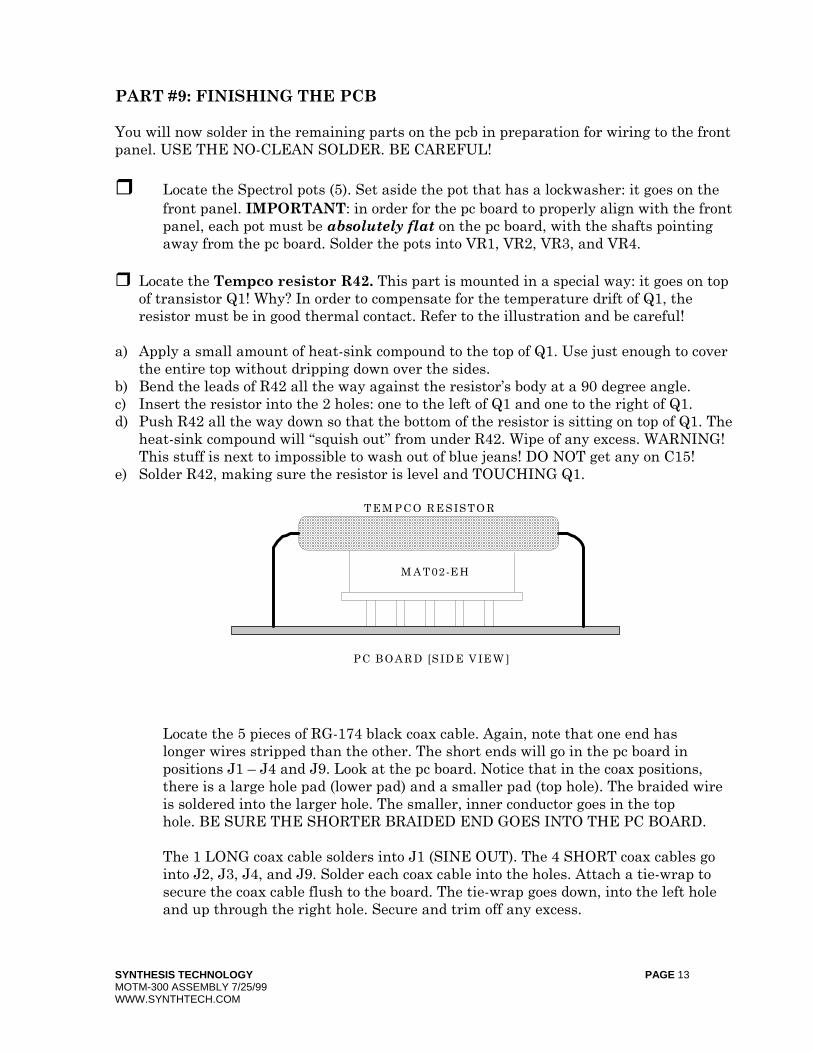
Locate the Tempco resistor R42. This part is mounted in a special way: it goes on top of transistor Q1! Why? In order to compensate for the temperature drift of Q1, the resistor must be in good thermal contact. Refer to the illustration and be careful!
a) Apply a small amount of heat-sink compound to the top of Q1. Use just enough to cover
the entire top without dripping down over the sides. b) Bend the leads of R42 all the way against the resistor’s body at a 90 degree angle. c) Insert the resistor into the 2 holes: one to the left of Q1 and one to the right of Q1. d) Push R42 all the way down so that the bottom of the resistor is sitting on top of Q1. The
heat-sink compound will “squish out” from under R42. Wipe of any excess. WARNING! This stuff is next to impossible to wash out of blue jeans! DO NOT get any on C15!
e) Solder R42, making sure the resistor is level and TOUCHING Q1.
Locate the 5 pieces of RG-174 black coax cable. Again, note that one end has longer wires stripped than the other. The short ends will go in the pc board in positions J1 – J4 and J9. Look at the pc board. Notice that in the coax positions,
there is a large hole pad (lower pad) and a smaller pad (top hole). The braided wire is soldered into the larger hole. The smaller, inner conductor goes in the top hole. BE SURE THE SHORTER BRAIDED END GOES INTO THE PC BOARD.
The 1 LONG coax cable solders into J1 (SINE OUT). The 4 SHORT coax cables go into J2, J3, J4, and J9. Solder each coax cable into the holes. Attach a tie-wrap to secure the coax cable flush to the board. The tie-wrap goes down, into the left hole and up through the right hole. Secure and trim off any excess.
M A T02-E H
PC B O A R D [SID E V IE W ]
TE M PC O R E SISTO R
SYNTHESIS TECHNOLOGY PAGE 14 MOTM-300 ASSEMBLY 7/25/99 WWW.SYNTHTECH.COM
Find the 4 orange/white/gray twisted wires. These are soldered into VR5 (COARSE), VR6 (WIDTH), SW2 (EXP/LIN switch) and SW3 (SYNC switch). In all cases insert the orange wire into the #3 hole, the white wire into the #2 hole, and the gray wire into the #1 hole. Solder each wire set.
Find the 2 long orange/white twisted pairs. They go into J5 (1V/OCT) and J6 (PWM IN). Solder the orange wire into the LEFT hole and the white wire into the RIGHT hole (the RIGHT hole has a more square pad).
Find the 3 red/black twisted pairs. They go into SW1, J7, and J8. Solder the black wire into the LEFT hole and the red wire into the RIGHT hole.
YOU ARE NOW FINISHED WITH THE PC BOARD WORK! BREAK TIME. PART #10: FRONT PANEL PREPARATION You will now attach components to the front panel. It is HIGHLY recommended that you use a set of hollow shaft nut drivers, NOT PLIERS, to tighten the nuts. This prevents scratching. NOTE: all references to part orientation is from the REAR of the panel.
Locate the 9 Switchcraft jacks. Notice that from the rear, there is a beveled corner. This corner is ALWAYS CONNECTED TO GROUND, USUALLY WITH THE
BRAIDED CONDUCTOR. Each jack has a flat washer, a lockwasher, and a ½” hex nut. Remove the nuts and washers from each jack. Place aside. Keep the lockwasher on the jacks.
Insert the 9 jacks/lockwashers, with the beveled corner in the upper right corner, into the 9 holes. Place the flat washer on the jack, then the hex nut. Hold the jack with one hand on the backside, keeping it ‘square’. Tighten the hex nut with a nut driver. NOTE: when tight, not much of the exposed threads of the jack are exposed.
Insert the 3 switches into the 3 smaller holes (SYNC, EXP/LIN, and AC/DC). CAUTION: DO NOT OVERTIGHTEN! Notice that there are 3 lugs, which we will refer to as ‘top’, middle’, and ‘bottom’. Depending on the switch manufacturer, the lugs may be marked ‘1 2 3’ or ‘ON’ and ‘ON’ with the center lug blank. Therefore, the instructions will simply refer to them as top, middle, and bottom as viewed from the rear of the panel. Remove the first hex nut, insert the switch with the locknut on the back of the panel, and replace the hex nut and secure. Be sure the switch is in a vertical alignment.

SYNTHESIS TECHNOLOGY PAGE 15 MOTM-300 ASSEMBLY 7/25/99 WWW.SYNTHTECH.COM
Locate the blue Bourns 100K pot. Note that it has 3 small lugs to attach the wires.
These lugs point downwards (towards the jacks). Remove the first hex nut and washer. Using a ½” nut driver, secure the pot by inserting it in the WIDTH hole with the toothed lockwasher on the rear of the panel. The flat washer goes on the front side, followed by the hex nut. BE SURE the 3 lugs point down.
Locate the 100K Spectrol 149 pot. Unfortunately, it does not have nice lugs to solder to! Instead, you will have to use a pair of needlenose pliers and form a small “hook” in each lead to attach the wires. You can to this before or after to secure the pot to the front panel. DO NOT bend the pot leads near the body: instead bend the leads at the very end of the leads. See the illustration. The pot goes in the COARSE hole, again, with the 3 leads pointing down.
You are now ready to attach the pc board to the bracket and then wire up to the panel. PART #11: ATTACH PC BOARD TO BRACKET/PANEL
In the HARDWARE bag, locate 4 #6-32 x 3/8 screws, 6 #6 KEPS nuts, and 4 spacers.
Locate the mounting bracket. The pc board attaches to the bracket, with the 4 screws threading from the top of the board, through the spacers, through the bracket, and then out the bottom of the bracket. The #6 KEPS nut attaches on the bottom of the bracket. Note the bracket has 2 long mounting flanges with a hole in each. These attach to the 2 threaded studs sticking out of the rear of the panel. The 4 pots each stick in its panel hole when the bracket is screwed down on the 2 threaded posts.
Attach the pc board to the bracket. The flanges will point upwards when the pc board is sitting on the bracket. Note that the bracket holes for the pc board are
actually oblong. This is to allow adjustment for the pc board to firmly press up against the back of the panel. As a start, set the 4 screws ALL THE WAY TO THE LEFT of the oblong holes. Loosely tighten the 4 KEPS nuts on the bottom.
THIS IS A VERY IMPORTANT STEP, SO PAY ATTENTION AND READ ALL OF IT BEFORE PROCEEDING! Note that each of the 4 pots on the pc board have 2 hex nuts and a flat washer. Remove the first hex nut and the washer. Set aside. What you will do now is adjust the remaining hex nuts so that when the bracket is all the way down on the panel’s threaded studs, all the pot hex nuts touch the rear
of the panel.

SYNTHESIS TECHNOLOGY PAGE 16 MOTM-300 ASSEMBLY 7/25/99 WWW.SYNTHTECH.COM
Screw (by hand) each hex nut on the pots so that it is all the way on (touching the face of the pot). Now, pick up the pc board/bracket assembly and carefully slide it over the 2 threaded studs, making sure the pots are aligned in the holes. Use 2 #6 KEPS nuts and tighten the bracket to the panel.
Loosen the 4 KEPS nuts on the bottom of the bracket. Slide the pcb ALL THE WAY
TO THE RIGHT AS FAR AS IT WILL GO, so that the 4 pot nuts are all pressing against the panel. By hand, put hex nuts on the outside threads of VR1 and VR4 to keep the pc board in place. Now, tighten the 4 KEPS nuts on the bracket. The pcb and bracket should be secure, with no gaps visible between the panel and the pot nuts. You may need to loosen the nuts on the pots, so that they are touching
the back of the panel. Again, make sure each pot’s nut is touching the back of the panel (no gaps!). There will be a gap from the edge of the pc board to the panel.
Remove the hex nuts on VR1 & VR4. For all of the pots, first put on the flat washer, then the hex nut. Tighten with a ½” nut driver. PART #12: FINISH WIRING TO THE PANEL Please read the following instructions carefully. In order to neatly attach the many wires to the front panel components, the wires are soldered in a specific order. You may find, in some cases, easier to first remove a component from the panel and solder the wires, then reattaching to the panel.
The first wire is the PULSE OUT coax on J4. Thread the coax down and in between the FM1 and FM2 jacks. Solder the braid to the beveled lug on the PULSE jack. Solder the inner conductor to the left lug. The top lug is open.
Next find the red/black twisted pair in the FM2 holes. BUT, before you solder the wires, you will need to get one of the resistor leads you saved and solder a short jumper from the top lug of FM2 to the beveled lug. This will short the input to ground with nothing plugged in: this reduces stray pickup that causes the VCO to “wander”. Since this jack is directly under the bracket, you may want to remove it first to attach this little wire. Once the shorting wire is soldered, locate the red/black twisted pair in the FM2 holes J8. Solder the RED wire to the left lug and the BLACK wire to the beveled lug.
Solder the SAW OUT coax in J3 to the SAW jack. Braid on the bevel, inner on the left.
Prepare the FM1 jack as the FM2: solder a scrap resistor lead from the top lug to the beveled lug. Find the red/black twisted wires in the FM1 holes J7. Solder the RED wire to the left lug and the black wire to the beveled lug. You will probably find it easier to thread the wire on to of the FM1 wire/Pulse wire and bring the wires up from the bottom side of the jack.
Solder the TRI OUT coax in J2 to the TRI jack.
SYNTHESIS TECHNOLOGY PAGE 17 MOTM-300 ASSEMBLY 7/25/99 WWW.SYNTHTECH.COM
Solder the SINE OUT coax in J1 to the SINE jack. Take 1 of the 3 remaining tie-wraps and attach around the 3 coax wires J1/J2/J3 about 1.25 inches (32mm) from the edge of the pc board. Clip off the excess.
Prepare the 1V/OCT jack with the last resistor lead scrap. Solder the lead from the top lug to the beveled lug. Locate the white/orange twisted pair in the 1V/OCT holes J5. Solder the WHITE wire to the left lug and the ORANGE wire to the beveled lug.
Locate the other long white/orange twisted pair in PWM IN J6. Solder the WHITE wire to the left lug and the ORANGE wire to the beveled lug. Locate a tie-wrap and secure the 2 orange/white pairs together. Place the tie-wrap directly above R24 (by the SYNC I/O coax on the pc board). Trim off any excess.
Next is the tricky one: SW3. This one is probably easier to remove it first, since the 2 long orange/white wires go right behind it. Locate the orange/gray/white twisted wire in the SW3 holes. Solder the ORANGE wire to the TOP lug of the switch. The WHITE wire solders to the MIDDLE lug and the GRAY wire solders to the BOTTOM lug. If you have additional heat-shrink tubing, you may desire to first place the tubing over the ends of the 3 wires, solder, and slide the tubing back over the solder lug. This is optional (this heat-shrink is NOT supplied with the kit). If you do remove it first, be SURE the orange wire is at the top when you replace the switch!
Locate the 4K7 resistor you were supposed to keep! Solder one lead of the resistor to the LEFT lug of the SYNC I/O jack. Solder the other lead to the TOP lug of the jack. You may first want to clip off about half of the leads to keep them short. Then, solder the coax as follows: the braid goes to the BEVELED lug, and the inner conductor goes to the TOP lug (NOT the LEFT one! The TOP one!).
Locate the SW1 red/black wires. These solder to the AC/DC switch. The BLACK wire goes to the top lug and the RED wire goes to the middle lug. The BOTTOM lug is not connected.
Locate the SW2 orange/gray/white wires. They solder to the EXP/LIN switch. The ORANGE wire solders to the TOP, the WHITE wire to the MIDDLE, and the GRAY wire to the BOTTOM lug.
Locate the VR6 (Initial Pulse WIDTH) orange/white/gray wires. These solder to the blue Bourns 100K pot. The GRAY wire goes on the LEFT lug, the WHITE wire goes on the CENTER lug (it is offset from the others slightly), and the ORANGE wire goes to the RIGHT lug. Attach the last tie-wrap around the wires to the 2 FM1 switches and this pot in the middle of the bundle. Trim the excess.
Locate the VR5 orange/gray/white wires (COARSE). These DO have heat-shrink on each lead. The GRAY wire goes on the LEFT lead, the WHITE wire goes to the

SYNTHESIS TECHNOLOGY PAGE 18 MOTM-300 ASSEMBLY 7/25/99 WWW.SYNTHTECH.COM
CENTER lead, and the ORANGE wire goes to the RIGHT lead. For each wire, bend a small J-shaped “hook” in the pot lead, slide the tubing over the wire (you may want to untwist the wires once or twice), and solder the wire to the pot lead. Do this for each wire. Then slide all 3 tubes up all the way until they touch the black body of the pot and shrink using a heat-shrink gun or other suitable heat source such as placing your soldering iron close but not touching the tubing.
Rotate all of the front panel pots fully counter-clockwise. Locate the KNOBS.
Notice each knob has a white line on it. Place the knob on the pot shaft, align the white line to the ‘0’ tick mark, and tighten the hex screw. The silver
part of the knob has a protective clear plastic overlay that can be removed if desired. Gently rub with your fingernail across it and it will peel off.
************************************************************************************
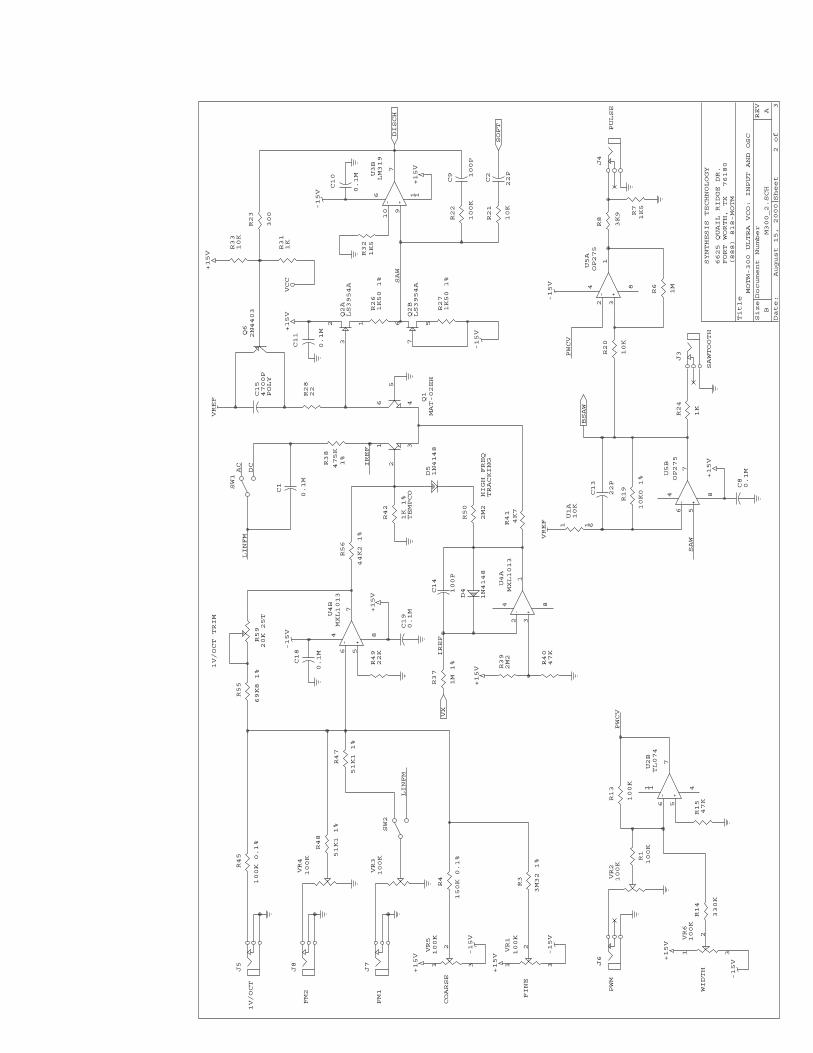
CONGRATULATIONS! YOU HAVE FINISHED BUILDING THE MOTM-300! ************************************************************************************ All that’s left to do is test it! But before we do, please read the following Theory of Operation. THEORY OF OPERATION The MOTM-300 VCO has 4 basic sections: a voltage summing amplifier for the control voltages, an exponential voltage-to-current converter, a sawtooth oscillator, and a waveshaper. Each of these sections is covered below. INPUT VOLTAGE SUMMER Refer to the schematic page marked M300_2.SCH for the following discussion. Since the ‘300 is in fact voltage-controlled, then one can assume one or more voltages set the operating frequency. Voltages come from 2 places: the initial frequency, which is set by the COARSE and FINE front panel pots, and the 3 CV inputs. All of these are added together to make a combined control voltage. The name of the game in VCO design is frequency stability. The ‘300 is called the “Ultra VCO” because no other VCO offered in a modular synth has been so painstakingly designed to be stable over time and temperature. And a major factor in maintaining long-term stability is careful design of the input summing amp. If this portion of the circuit drifts, then the entire VCO drifts as well. It is also important that the main +/-15VDC power supply not drift as well (or be noisy or have any sort of signals imposed on the supply lines). This is why the MOTM-900 is highly recommended for powering the ‘300 VCOs, since it contains the LM723 voltage regulator.
SYNTHESIS TECHNOLOGY PAGE 19 MOTM-300 ASSEMBLY 7/25/99 WWW.SYNTHTECH.COM
The first critical part in the summer is the op-amp itself, U4B. This op amp is a LT/MXL1013, a low-offset and very low-drift DC accurate part. The critical parameter is choosing this part is the output offset voltage and the input bias current drift over temperature. Common op amps used in this application (like the TL072) have 10-20 times greater drift than the 1013. Remember, even the worst “trained” ear can hear the VCO drift out of tune if the voltage to the exponential generator is more than 200µV! Having chosen the proper summing op amp, the next overlooked design decision is in picking the correct type of resistors in the summing circuitry. Most designs use standard 1% metal-film resistors. What is “standard” about them is the temperature coefficient of the resistance. Yes, resistors will change their value with temperature! The normal 1% resistor found in other VCOs drift 200ppm (parts per million) per degree C. A 1MΩ resistor drifts 200 Ω every 1 degree C the ambient temperature does up and down. A 15C temperature drift in a modular is not uncommon as the circuitry heats up and stabilizes. Well, this is another small, but easily corrected, drift element. The ‘300 uses special, very low temperature drift resistors called RN55Es. These resistors drift 10 times less than standard 1% resistors. A side benefit: no color bands to decode! The value is printed on the resistor body. Some resistors used are also a very tight 0.1% tolerance. Lastly, the COARSE and FINE pots use very low drift cermet resistive material. This means when you set those front panel pots, the frequency does not drift because the resistance of the pots is changing with temperature. There is a special, very important gain function required from the input voltages to the exponential converter: a 1 volt change in the input must appear as a 18.02mv change on the base of Q1 pin 2. This will be explained later on. The thing is, we need to attenuate so that this occurs. This is done in 2 stages. The first stage is set by the trim pot R59 in series with R55. The sum of these 2 resistors set the output voltage of U4B as: Vout = - (R59 + R55)/R45 <<<since R45 is our 1V/Oct input R59 sets the overall response to 1 volt/octave. The voltage output from U4B then goes to a second, special voltage divider consisting of R56 and R42. Resistor R42 is a resistor that is actually touching transistor Q1 (assuming you built it correctly!). This resistor is made of special wire that changes its resistance +3500ppm. Hmmmm…didn’t we just say that the 200ppm of a 1% resistor was “too bad for MOTM”? The reason R42 is “designed bad” on purpose is that the collector current of Q1 changes -3300ppm per degree C (in a negative direction). The Tempco resistor R42 makes the voltage divider alter its “division ratio” in a positive direction. Therefore, the intent of R42 is to cancel out the temperature drift of Q1. This temperature drift of collector current is the main drift contributor in the VCO. The “nominal” voltage divider of R56 and R42 is:
SYNTHESIS TECHNOLOGY PAGE 20 MOTM-300 ASSEMBLY 7/25/99 WWW.SYNTHTECH.COM
Vout = R42 / (R42 + R56) or a ratio of 1:45.2 If the desired ratio is (1/.01802) or 1:55.494, then the input summer trimmer is set to “make up” the difference. A good EE homework question: what exact value of R59 makes the total ratio 1:55.494??? [OK the answer is 11.66K]. Let’s examine how the MOTM-300 is setup on the inputs. First, there is a dedicated 1V/Oct jack J5 that feeds R45 directly. The other 2 inputs (FM1 and FM2) are first attenuated and then fed not to 100K resistors, but to 51K1 resistors. This is so non-standard scales of older equipment can be used (most notably, the 1.21V/Oct of the EML 101). Also, the 51K1 allows wider modulation swings than the 1V/Oct input. The initial frequency is set by the 2 panel pots COARSE (VR5) and FINE (VR1). Note the FINE resistor, R3, is a high value of 3M32Ω. This is how the voltage range is scaled to be narrower. Lastly. resistor R49 is used to balance the input bias current flowing into U4B, which in turn reduces drift over temperature. EXPONENTIAL CONVERTER/SAWTOOTH OSCILLATOR The VCO works by applying a negative current to a capacitor. Why a current? Because a capacitor behaves according to the following relationship:
Icap = C (dV/dt) Where Icap is the current in the cap and (dV/dt) is the rate of change of the voltage across the cap with time. The phrase “negative current” means we are pulling current out of a charged capacitor, thus discharging it. So, the clever reader will note that if we have a constant C (capacitance value), then changing the current Icap changes dV/dt in a linear fashion. And what exactly is dV/dt? Well, if the voltage change is constant (say 5 volts) then that means 1/dt changes and of course 1/dt is FREQUENCY! (You in the back of the class! Wake up!) So here is how we make a VCO: you pick some cap C, pick some voltage to charge to (or in our case a voltage to discharge from) dV, and then feed it Icap to change the frequency. What could be easier??? Well, the difficulty is that for a musical VCO, we want a doubling effect. See, the Western 12-note musical scale is arranged so that an octave is defined as a frequency doubling every 12 notes. If the note ‘A’ is set at 440Hz, 1 octave up is 880Hz and one octave down is 220Hz. Our basic little VCO is linear: if the low A is 220Hz, the next A would be 440Hz but the NEXT one is 660Hz! WRONG! What’s a poor circuit designer to do?
SYNTHESIS TECHNOLOGY PAGE 21 MOTM-300 ASSEMBLY 7/25/99 WWW.SYNTHTECH.COM
Thankfully, Bob Moog already figured it out: you use the fact that the collector current of a transistor doubles every 18.02mv change of the base-emitter voltage. How does it do that? That’s a long semiconductor device essay: there are plenty of books that derive this. Trust me. Let’s look back at the schematic. Our VCO is based around the humble, but loveable, capacitor C15. One end of C15 is tied to a reference voltage called VREF. Assume for now that VREF is +5V. The other end of the cap is tied to the collector of one half of dual transistor Q1. Q1 is a very special device: without it our VCO would not be exponential. It is a dual transistor: there are 2 independent NPN transistors on the same die. Why? Because the transistors will drift with temperature and we want them to both drift the same amount (i.e. track each other over temperature). What exactly drifts? The collector current! The very thing that determines the frequency of our VCO! Therein lies the problem: the transistor gives us our desired doubling, but we pay the price of a rather large drift. Before we dive in, just a quick note. It very easy to think of analog circuits in what I call a “positive-voltage frame of reference.” You think about all the voltages in a circuit being positive with respect to ground. However, this VCO is designed from a “negative-voltage frame of reference.” So if some things seem ‘backwards’ to your normal thoughts, study it again. The cap in the ‘300 is not “charged” from ground to +5V. Rather, it is “discharged” from +5V to ground. In order to do this, we “suck” current out of the capacitor with Q1. The base of the first transistor is at ground. We then must change the voltage on the emitter to be below ground: that’s a ‘negative’ voltage. The other half of our dual op amp summer U4A is used for this. The VCO has a ‘zero voltage’ frequency: this is the frequency when the output of the summing and is 0.0V. This is set by a reference current called IREF. The current is set by resistor R37, a 1.0M 1% low drift part. The current is derived from voltage source VX. Assume for the time being that VX = 5V. IREF is then: IREF = 5/1M Or 5µA. It is slightly less than this because the + input of the op amp is biased up to 300mv by resistor divider R39/R40. Why? This is to protect Q1 from having its base-emitter junction reverse biased. Assuming a 5µA IREF and the base of BOTH transistors is 0V, then since the emitters are tied together, the collector currents are equal (5µA in both) and our frequency is: Fout = (I/C) / 5V or about 200Hz. This is simply a compromise to get the most useful part of the musical scale with positive-going control voltages (like from a MIDI-CV converter). Of course, the COARSE/FINE pots offset this point both up & down.
SYNTHESIS TECHNOLOGY PAGE 22 MOTM-300 ASSEMBLY 7/25/99 WWW.SYNTHTECH.COM
Looking back at the circuit: if IREF is a constant then the base-emitter voltage changes at Q1 pin 2 will cause current changes in the collector Q1 pin 6. Since C is fixed and our reset threshold is set at +0V (a dV of 5), a simple frequency equation is: Fout = I / 2.35 x 10E-8 So if I gets bigger, Fout goes up. This makes sense: if we suck more current out of the cap, the faster it discharges towards 0V and, hence, the frequency increases. If I = 1ma, the VCO oscillates about 40kHz. Generally speaking, Q1 is operating with collector currents from 500nA to 500µA. The components D5 and R50 set the ‘High Frequency Tracking’. At higher and higher current levels, the non-zero resistance of the emitters starts introducing errors. The VCO runs ‘flat’ because there is a slight error in the collector currents. The diode/resistor compensate for this by modulating the base current slightly. D4 is another protection clamp for Q1 and C4 is a stability cap because U4A is running “open loop” and we over-dampen it to prevent oscillations. The remainder of the sawtooth VCO circuitry has to do with when the capacitor C15 voltage reaches 0V, then turning on the “discharge” transistor Q6 (actually, it shorts the cap to VREF). The voltage on C15 is first buffered by dual JFET Q2. The JFET is configured as a zero-offset follower. The FET Q2B is a constant current source that biases the other half Q2A. Since this is a monolithic, dual JFET , the Vgs voltages are matched and no offset voltage is present (in reality, the offset will be very small, on the order of 5µV). Since the cap voltage is “looking into” the gate of Q2A, the input impedance is very high: on the order of 500MΩ. This isolates the exponential converter control current from the comparator U3B. Why is this necessary? Because the LM319 comparator has a large input bias current that will vary over temperature. This input bias current would “steal” capacitor current if the JFET buffer was not present and cause drift. The JFET also “steals” current, but it is on the order of picoamps, as opposed to the LM319’s nanoamps. Big difference! The LM319 compares the sawtooth voltage to ground (as set by R32). Since it is an open-collector NPN output stage and we are controlling a PNP, the base of the PNP is biased by R33 & R31 to 6V. This is needed because the emitter of the PNP is at +5V (VREF) and in order to turn it off and on, we need to drive the base higher by at least a Vbe drop (say 0.7V max). Why not bias it higher, to say +15V? Because the higher the bias voltage, the longer it will take to turn the PNP off due to minority charge storage. The RC network of R22/C9 provides AC hysteresis to further speed up the comparator. R28 corrects for the finite reset time of the LM319 (on the order of 200ns). Note that since U3B is open-collector, this is a convenient node to use as a HARD SYNC input. That is exactly what is done: see the sync discussion in the following paragraphs. WAVESHAPING
SYNTHESIS TECHNOLOGY PAGE 23 MOTM-300 ASSEMBLY 7/25/99 WWW.SYNTHTECH.COM
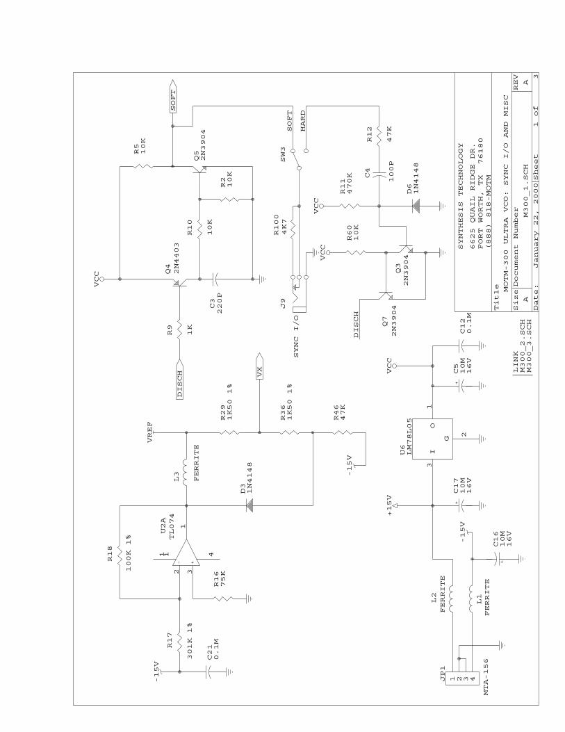
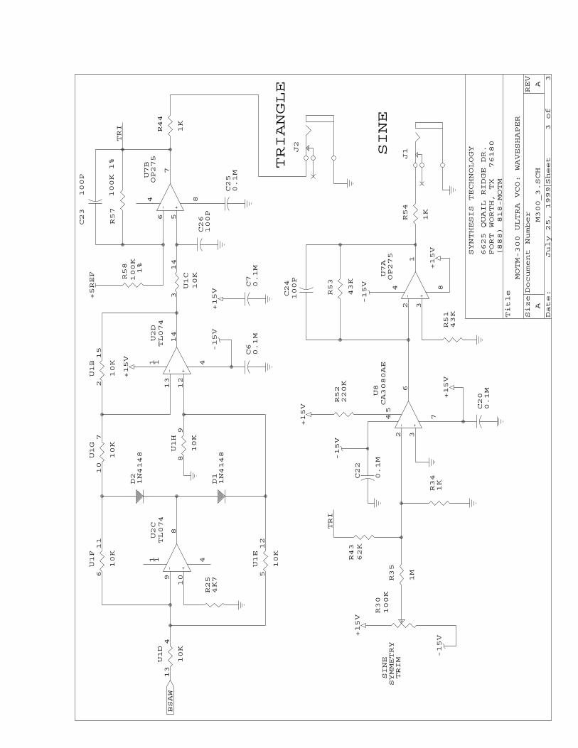
Once we have generated a negative slope sawtooth, the pulse; triangle; and sine waveforms can be derived. Since MOTM uses de facto +/-5V pk-pk waveforms, we need a level shift of the +5V – 0V sawtooth. Op amp U5B takes the sawtooth and via bias resistor U1A (part of the resistor network) and shifts the waveform to +/-5V pk-pk. The pulse is simply a comparison of the output sawtooth (called BSAW) to a control voltage PWCV. Op amp U5A compares BSAW to the summer U2B output. U2B is similar to the summing amp on the VCO CV inputs. The pot VR6 sets the initial pulse width. PWM voltage is summed via VR2/R1 with the initial setting and sent to U5A. Since the U5A is at a very high gain (R6/R20 or 100 times), the output voltage on pin 1 will swing about +/-14V pk-pk. Resistor divider R7/R8 sets this to the desired +/-5V pk-pk. The triangle/sine waveshaper is on the schematic page M300_3.SCH The triangle wave is formed by full-wave rectifying the sawtooth. U2C and U2D op amps and their associated circuitry (D1/D2 and resistor pack U1) generate a triangle at the output of U2D. This triangle has a small ”glitch” at the peaks due to the finite switching times of the 2 diodes. A low-pass filter (U1C/C26 and R57/C23) removes the glitch. The sine waveshaper uses a CA3080 OTA (U8) that is biased by R52 to be “overdriven” by the triangle amplitude set by R43/R34. The differential transistors on the OTA’s input are operated in the “knee” of their transfer function. The input triangle wave “sweeps” across the “knee” (the Ic versus Vbe curve) and the result is an approximation of a sine wave. Since the output of the CA3080 is a current, op amp U7A and resistor R53 form a I/V converter. Cap C24 removes a tiny glitch on the sine due to the slew rate of the 3080. Trimmer R30 is used to add a DC offset to the input triangle to symmetrically bias the input stage. This trimmer will adjust the positive/negative symmetry of the output sine wave. REFERENCE GENERATOR/SYNC CIRCUIT Refer to the schematic page M300_1.SCH U6 is a small current +5V regulator used to power the sync logic. This prevents the fast & narrow sync pulses from coupling back into the power supply. The VCO uses 2 reference voltages: VFRF and VX. Op amp U2A generates the +5V VREF signal by scaling the –15V supply via resistors R17/R18. The second reference VX is used to set the VCO’s 5µA reference current. However, it has a special circuit using diode D3 to have a temperature coefficient. The diode’s forward voltage changes 2mV/C and this is used to cause the IREF current to “drift”. Why? This compensates for drift in the capacitor C15 as well. The amount of “drift” is set by scaling resistors R29/R36.
SYNTHESIS TECHNOLOGY PAGE 24 MOTM-300 ASSEMBLY 7/25/99 WWW.SYNTHTECH.COM
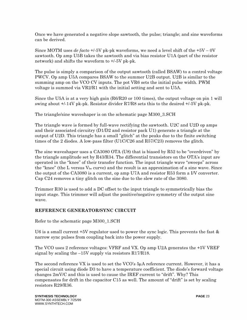
The VCO has 2 types of sync: hard and soft. Hard sync causes the VCO to immediately reset the sawtooth when a sync pulse is detected. This is a simple operation because we picked an open-collector comparator. Transistors Q3/Q7 are used for this. The sync input is AC coupled by C4 and clipped by D6. This allows most waveforms over 2V pk-pk to be used as a sync signal. The soft sync is a little more complicated! First, we generate a unique sync output signal using the 2 transistors Q4/Q5. This is basically a buffer and “pulse stretcher” of the reset signal for the VCO. Here is a picture of the SYNC I/O pulse.
The sync signal from another VCO is AC coupled into the comparator via R21/C2 (see page M300_2.SCH). It is important to note that it is weakly-coupled: if the sawtooth voltage is above 0.5V or so, the sync pulse is ignored. However, if the sawtooth is near ground, the incoming pulse “glitches” the comparator just enough to cause a reset. PRELIMINARY CHECK-OUT & CALIBRATION The VCO needs two adjustments: the 1V/Oct tracking and the sine wave symmetry. If you have access to an oscilloscope, this will greatly reduce your efforts, especially if you suspect the VCO is not operating properly. At the minimum, a good DVM is needed to check voltages at different points on the circuit if there is a problem. SETTING THE 1V/OCT TRIMMER First, apply power to the VCO and test each of the 4 outputs for audio. Set the COARSE and FINE pots to center positions. If all is good, the VCO should oscillate at about 200Hz. Note that each output will sound louder or softer relative to each other. If you have a scope, examine each output for proper wave shape (we will adjust the sine later). If you do not have any audio output, please proceed to the TROUBLESHOOTING section.
SYNTHESIS TECHNOLOGY PAGE 25 MOTM-300 ASSEMBLY 7/25/99 WWW.SYNTHTECH.COM
In order to properly set the tracking, you need a known, stable source of control voltages. Usually, these come from a MIDI-CV converter such as a Kenton Pro-2000. If you have a keyboard that outputs CV (such as a Roland SH-101), you can use that. Use a DVM to verify that your voltage source is accurately outputting 1V/Octave. DO NOT use a cheap analog meter for this! Let the VCO stay powered up for 3 minutes before adjusting the trimmer. This lets the 5 separate temperature compensation loops stabilize. Using a very small, flat-bladed screwdriver rotate the trimmer screw until you detect a faint “click-click” as you turn it clockwise. This is the end of rotation of the trimmer: note that it is a 25-turn pot. Now, count 12 full rotations of the trimmer in the opposite direction (counter-clockwise). This is approximately the 1V/Oct set point. You will be close, but not exact. In order to properly set the octave intervals, you have several options:
a) Use your wonderful sense of pitch. b) Use a frequency counter, if available. Use the PULSE output to the counter. c) Use another synth you think is in tune, and compare the pitches over speakers.
In any case, the procedure is the same:
a) Set the COARSE and FINE pitches to a starting point. A440 is a good choice if you are using a freq. counter.
b) Play a note on the keyboard. c) Play a note 1 octave higher. d) Adjust the trimmer for the proper pitch. Keep playing/adjusting back and forth
until this 1 octave is set. e) Now play 4 or 5 octaves apart, without touching the COARSE/FINE pots.
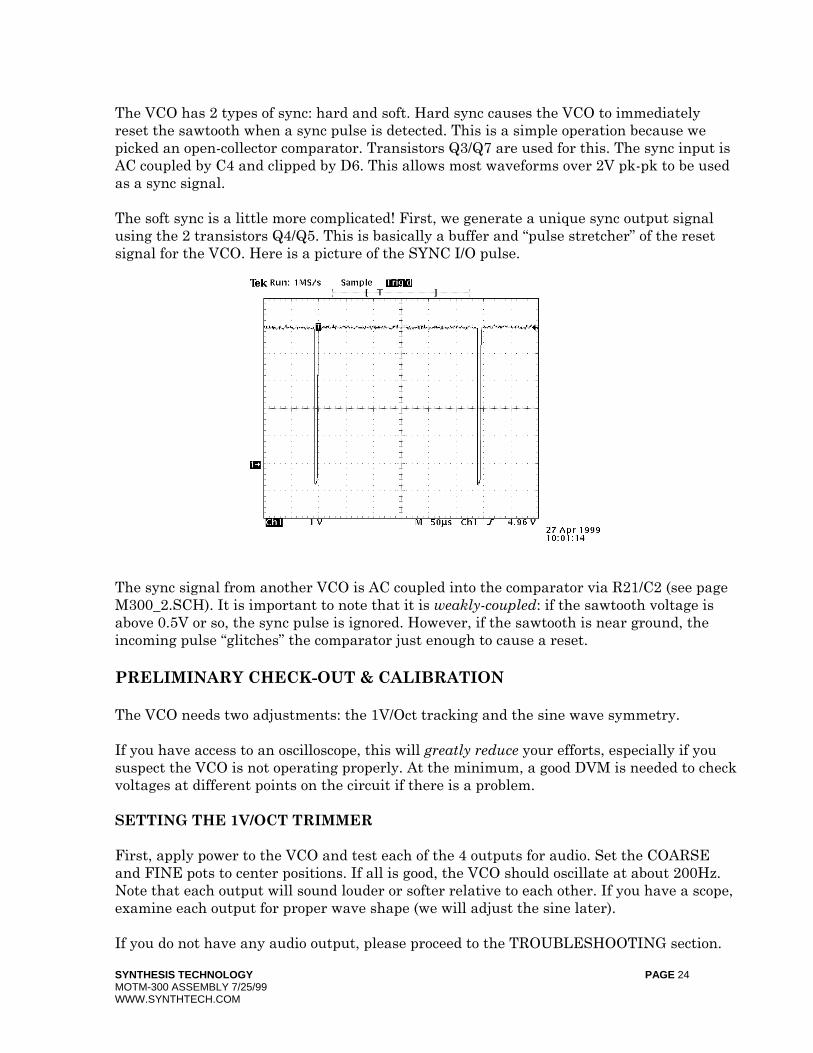
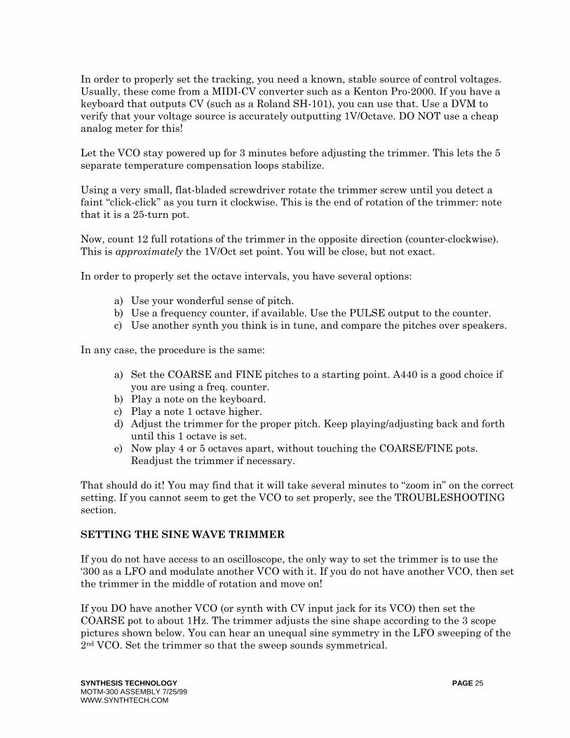
Readjust the trimmer if necessary. That should do it! You may find that it will take several minutes to “zoom in” on the correct setting. If you cannot seem to get the VCO to set properly, see the TROUBLESHOOTING section. SETTING THE SINE WAVE TRIMMER If you do not have access to an oscilloscope, the only way to set the trimmer is to use the ‘300 as a LFO and modulate another VCO with it. If you do not have another VCO, then set the trimmer in the middle of rotation and move on! If you DO have another VCO (or synth with CV input jack for its VCO) then set the COARSE pot to about 1Hz. The trimmer adjusts the sine shape according to the 3 scope pictures shown below. You can hear an unequal sine symmetry in the LFO sweeping of the 2nd VCO. Set the trimmer so that the sweep sounds symmetrical.
SYNTHESIS TECHNOLOGY PAGE 26 MOTM-300 ASSEMBLY 7/25/99 WWW.SYNTHTECH.COM
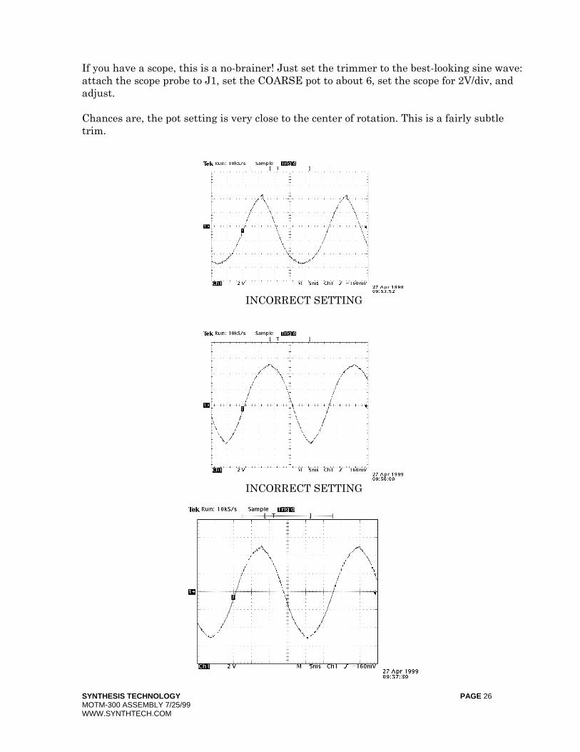
If you have a scope, this is a no-brainer! Just set the trimmer to the best-looking sine wave: attach the scope probe to J1, set the COARSE pot to about 6, set the scope for 2V/div, and adjust. Chances are, the pot setting is very close to the center of rotation. This is a fairly subtle trim.
INCORRECT SETTING
INCORRECT SETTING
SYNTHESIS TECHNOLOGY PAGE 27 MOTM-300 ASSEMBLY 7/25/99 WWW.SYNTHTECH.COM
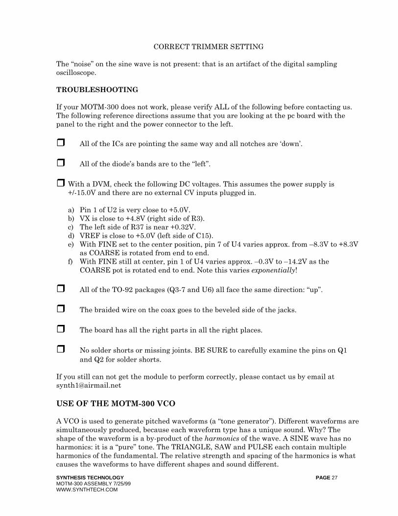
CORRECT TRIMMER SETTING
The “noise” on the sine wave is not present: that is an artifact of the digital sampling oscilloscope. TROUBLESHOOTING If your MOTM-300 does not work, please verify ALL of the following before contacting us. The following reference directions assume that you are looking at the pc board with the panel to the right and the power connector to the left.
All of the ICs are pointing the same way and all notches are ‘down’.
All of the diode’s bands are to the “left”.
With a DVM, check the following DC voltages. This assumes the power supply is +/-15.0V and there are no external CV inputs plugged in.
a) Pin 1 of U2 is very close to +5.0V. b) VX is close to +4.8V (right side of R3). c) The left side of R37 is near +0.32V. d) VREF is close to +5.0V (left side of C15). e) With FINE set to the center position, pin 7 of U4 varies approx. from –8.3V to +8.3V
as COARSE is rotated from end to end. f) With FINE still at center, pin 1 of U4 varies approx. –0.3V to –14.2V as the
COARSE pot is rotated end to end. Note this varies exponentially!
All of the TO-92 packages (Q3-7 and U6) all face the same direction: “up”.
The braided wire on the coax goes to the beveled side of the jacks.
The board has all the right parts in all the right places.
No solder shorts or missing joints. BE SURE to carefully examine the pins on Q1 and Q2 for solder shorts.
If you still can not get the module to perform correctly, please contact us by email at [email protected] USE OF THE MOTM-300 VCO A VCO is used to generate pitched waveforms (a “tone generator”). Different waveforms are simultaneously produced, because each waveform type has a unique sound. Why? The shape of the waveform is a by-product of the harmonics of the wave. A SINE wave has no harmonics: it is a “pure” tone. The TRIANGLE, SAW and PULSE each contain multiple harmonics of the fundamental. The relative strength and spacing of the harmonics is what causes the waveforms to have different shapes and sound different.
SYNTHESIS TECHNOLOGY PAGE 28 MOTM-300 ASSEMBLY 7/25/99 WWW.SYNTHTECH.COM
The “classic” synthesizer patch is as follows: a) Your keyboard’s control voltage into the 1V/Oct input jack b) An output waveform into the audio IN of a VCF c) Output of the VCF into a VCA d) 2 ADSR EGs triggered from the keyboard: one for the VCF and one for the VCA Rather than explore how to patch the ‘300, we will instead go over what the ‘300 does. RULE #1 Voltage in = Frequency out You change the frequency (hence, ‘pitch’) of the ‘300 with control voltages. These control voltages can be from a DC source (ie your MIDI-CV converter), a slowly-changing waveform (LFO, S&H, sequencer) or audio (output from another MOTM-300). The 3 places you can stick a CV into the VCO are: a) the 1V/OCT jack. This has no attenuator. It runs “straight in” to the summing amp. b) The FM1 jack. This is the “fancy” CV input. You can select EXP (exponential) or LIN
(linear) FM. The AC/DC switch, active only for LIN mode, will allow more timbre effects depending on the input waveform. The FM1 pot attenuates the CV applied. Note that FM1 and FM2 CV inputs are NOT 1V/Oct unless the pots are set just right. Rather, these are useful for frequency sweeps and effects. They have a wider range of modulation (for the same applied voltage) as the 1V/OCT input. FM1 and FM2 can run up to 0.5V/Oct (double the range).
c) The FM2 jack. Simple attenuator. At any instant in time, all 3 of these inputs are ADDED to the COARSE and FINE settings to produce the output frequency. RULE #2 Different waveforms sound….. different The 4 waveforms produced by the VCO each are useful in different ways. SINE and TRIangle waves are “mellower” because they have weak harmonics. They are also the most popular waveforms for use as a LFO signal. SAWtooth and PULSE waves are “raspy” and “buzzier/reedy” due to very strong harmonics. The PULSE is a special case, because we have 2 separate controls to change it’s sound. The harmonic content of the PULSE is a function of it’s width (more precisely, it’s ratio of the +5V time versus the –5V time. This is called ‘duty cycle’). Changing the duty cycle changes the harmonic content. In fact, the early CASIO synths created all of their sounds by rapidly changing the pulse width in a specific pattern. This is called PWM: Pulse Width Modulation. The MOTM-300 can also perform PWM. The control WIDTH sets the initial duty cycle from 10% to 90% (note 0 and 100% = DC or NO AUDIO OUTPUT). If a voltage is applied to the PWM jack, the PULSE output changes. A positive CV makes the PULSE ‘wider’. The PWM control attenuates the applied CV. PWM is loads of fun! Be sure to freely use all sorts of wacky CV signals to modulate it.
SYNTHESIS TECHNOLOGY PAGE 29 MOTM-300 ASSEMBLY 7/25/99 WWW.SYNTHTECH.COM
There is no set ‘rule’ that relates a desired sound to a certain waveform. All we can suggest is: experiment!! RULE #3 You can use audio signals to FM modulate Remember the Yamaha DX-7? It generated it’s sounds by using 6 VCOs (they were digital), connected in different ways (called ‘algorithms’), all FMing each other. One would initially suspect this is a novel white noise generator, but if the FM amounts are enveloped, you can create a wide sound palette. The “trick” is that these VCOs were not exponential, but linear response. The MOTM-300 VCO can also be FM’ed in a linear mode. Use the FM1 input and place the switch to LIN. Use an AUDIO source (like another ‘300’s SINE output) to modulate. You can generate some quite interesting tones this way. Here are some pointers/tips:
a) You may hear a pitch shift when switching from EXP to LIN. THIS IS NORMAL. IT AIN”T BROKE!
b) You may hear a pitch shift when switching from AC to DC. Is is due to the AC blocking capacitor being switched in/out.
c) You will get different timbres in AC than DC only if the modulating waveform HAS a DC component. A DC component is a frequency offset.
Lastly, you can also feedback the output(s) of a VCO back into itself! What’s all this SYNC business? Using a single VCO in a patch can be done, but most “interesting”, full-bodied sounds are a result of using multiple VCOs in parallel (ie each receiving the same CV input from the keyboard and adding the outputs together). The VCOs are detuned from each other to produce lush, beating tones. What is beating? This is the term used to describe an audible “warble” generated when 2 (or more) VCO outputs are mixed together. If the 2 frequencies are not integer multiples of each other EXACTLY, the beating is heard. The ‘beat frequency’ is the difference in the 2 signals: if one VCO is 100Hz and the other is 100.5Hz you will hear a 0.5Hz ‘beat’. In some cases, you WANT beating to occur. In others, the desired sound does not want this effect. This where SYNC comes into play. SYNC is a method to eliminate the beat frequencies. This is done electrically by causing a VCO’s output waveform to “line up” with another waveform by resetting the VCO capacitor (in the MOTM-300, that’s C15). Using the HARD/SOFT switch and the SYNC I/O jack In order to fit all the functions on the front panel, the SYNC controls are shared between HARD and SOFT modes. The following discussion is easier if you look at the schematic M300_1.SCH page at the SYNC logic.
SYNTHESIS TECHNOLOGY PAGE 30 MOTM-300 ASSEMBLY 7/25/99 WWW.SYNTHTECH.COM
The SYNC I/O jack has TWO FUNCTIONS: a) When the SYNC switch is in the HARD position, the jack is AN INPUT ONLY. You
feed a waveform FROM ANOTHER VCO (any shape will do) into the SYNC I/O jack. b) When the SYNC switch is in the SOFT position, the jack is BOTH AN INPUT AND
AN OUTPUT (BI-DIRECTIONAL). Narrow, +5V pk-pk pulses appear on the jack. You can connect several VCOs together (via a multiple, see the MOTM-940), all sharing same SYNC I/O signals. This is discussed later on.
In summary: HARD SYNC – A waveform from VCO #1 drives the SYNC I/O jack of VCO #2. It DOESN’T MATTER in what position VCO#1’s SYNC switch is set to IF YOU USE one of the 4 waveforms as the driving signal. However, there is a built-in “trick”: if VCO #1 is set to SOFT, it’s SYNC I/O jack will output the narrow pulse signal. You CAN USE THIS to HARD sync VCO #2, thereby preserving all 4 waveforms on VCO #1. SOFT SYNC – All VCOs are on a common “sync bus”. If using 2 VCOs, connect a patch cord between the two SYNC I/O jacks. Be SURE both VCO’s are set to SOFT. If synching more than 2 VCOs, use a multiple: run a patch cord FROM each VCO’s SYNC I/O jack to the multiple. This will connect ALL of the SYNC I/O signals together! Now that we have talked about how to use the switches/jacks, let’s discuss the difference between hard and soft sync. USING HARD SYNC Hard sync is by far the most commonly used form of sync. If you want to completely get rid of beating, use hard sync. In the following discussion, we will only talk about a 2 VCO setup. You can extrapolate this to synching more that 2 VCOs. Hard sync is best understood if you consider a MASTER VCO and a SLAVE VCO. The SLAVE’s frequency is altered by the MASTER’s frequency. For simplicity, lets assume the SLAVE’s ouput is a SAW and the Master is feeding a PULSE waveform to it. The MASTER and SLAVE are set to different frequencies, and there is a beat. Now, when we SYNC, the beating disappears because whenever the MASTER’s PULSE output crosses 0 Volts, it FORCES the SLAVE’s SAWtooth to reset back to +5V. The SLAVE’s SAW waveform DID NOT GET TO CROSS 0V, SO IT’S FREQUENCY IS ALTERED.
SYNTHESIS TECHNOLOGY PAGE 31 MOTM-300 ASSEMBLY 7/25/99 WWW.SYNTHTECH.COM
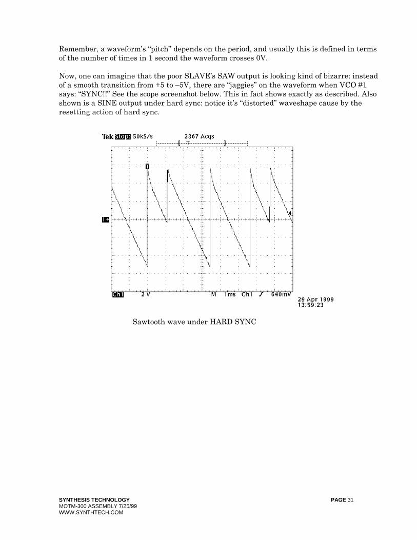
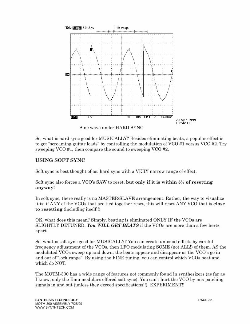
Remember, a waveform’s “pitch” depends on the period, and usually this is defined in terms of the number of times in 1 second the waveform crosses 0V. Now, one can imagine that the poor SLAVE’s SAW output is looking kind of bizarre: instead of a smooth transition from +5 to –5V, there are “jaggies” on the waveform when VCO #1 says: “SYNC!!” See the scope screenshot below. This in fact shows exactly as described. Also shown is a SINE output under hard sync: notice it’s “distorted” waveshape cause by the resetting action of hard sync.
Sawtooth wave under HARD SYNC
SYNTHESIS TECHNOLOGY PAGE 32 MOTM-300 ASSEMBLY 7/25/99 WWW.SYNTHTECH.COM
Sine wave under HARD SYNC So, what is hard sync good for MUSICALLY? Besides eliminating beats, a popular effect is to get “screaming guitar leads” by controlling the modulation of VCO #1 versus VCO #2. Try sweeping VCO #1, then compare the sound to sweeping VCO #2. USING SOFT SYNC Soft sync is best thought of as: hard sync with a VERY narrow range of effect. Soft sync also forces a VCO’s SAW to reset, but only if it is within 5% of resetting anyway! In soft sync, there really is no MASTER/SLAVE arrangement. Rather, the way to visualize it is: if ANY of the VCOs that are tied together reset, this will reset ANY VCO that is close to resetting (including itself!!) OK, what does this mean? Simply, beating is eliminated ONLY IF the VCOs are SLIGHTLY DETUNED. You WILL GET BEATS if the VCOs are more than a few hertz apart. So, what is soft sync good for MUSICALLY? You can create unusual effects by careful frequency adjustment of the VCOs, then LFO modulating SOME (not ALL!) of them. AS the modulated VCOs sweep up and down, the beats appear and disappear as the VCO’s go in and out of “lock range”. By using the FINE tuning, you can control which VCOs beat and which do NOT. The MOTM-300 has a wide range of features not commonly found in synthesizers (as far as I know, only the Emu modulars offered soft sync). You can’t hurt the VCO by mis-patching signals in and out (unless they exceed specifications!!). EXPERIMENT!!
SYNTHESIS TECHNOLOGY PAGE 33 MOTM-300 ASSEMBLY 7/25/99 WWW.SYNTHTECH.COM
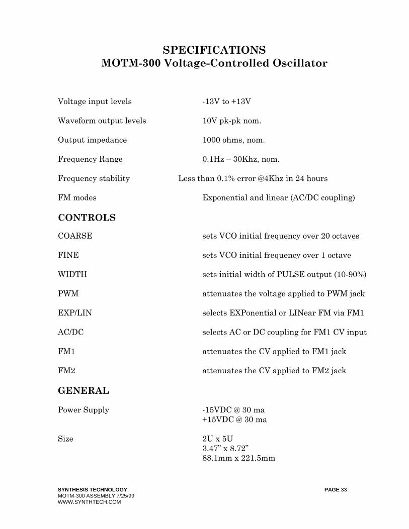
SPECIFICATIONS MOTM-300 Voltage-Controlled Oscillator
Voltage input levels -13V to +13V Waveform output levels 10V pk-pk nom. Output impedance 1000 ohms, nom. Frequency Range 0.1Hz – 30Khz, nom. Frequency stability Less than 0.1% error @4Khz in 24 hours FM modes Exponential and linear (AC/DC coupling) CONTROLS COARSE sets VCO initial frequency over 20 octaves FINE sets VCO initial frequency over 1 octave WIDTH sets initial width of PULSE output (10-90%) PWM attenuates the voltage applied to PWM jack EXP/LIN selects EXPonential or LINear FM via FM1 AC/DC selects AC or DC coupling for FM1 CV input FM1 attenuates the CV applied to FM1 jack FM2 attenuates the CV applied to FM2 jack GENERAL Power Supply -15VDC @ 30 ma +15VDC @ 30 ma Size 2U x 5U 3.47” x 8.72” 88.1mm x 221.5mm

SYNTHESIS TECHNOLOGY PAGE 34 MOTM-300 ASSEMBLY 7/25/99 WWW.SYNTHTECH.COM
Depth behind panel 4.375 inches (111mm)
Date: January 22, 2000Sheet
1of
3
SizeDocument Number
REV
AM300_1.SCH
A
Title MOTM-300 ULTRA VCO: SYNC I/O AND MISC
(888) 818-MOTM
FORT WORTH, TX 76180
6625 QUAIL RIDGE DR.
SYNTHESIS TECHNOLOGY
R5
10K
SOFT
VCC
R9
1K
Q4
2N4403
VREF
L3
FERRITE
DISCH
-15V
R17
301K 1%
R18
100K 1%
3
2
1
41 1U2A
TL074
R16
75K
C21
0.1M
D3
1N4148
R29
1K50 1%
R36
1K50 1%
VX
C3
220P
R10
10K
SYNC I/O
J9
R100
4K7
R2
10K
Q5
2N3904
SW3
SOFT
VCC
D6
1N4148
R12
47K
R11
470K C4
100P
HARD
VCC
DISCH
VCC
Q3
2N3904
Q7
2N3904
R60
10K
-15V
R46
47K
+15V
I 3
G
2
O 1
U6
LM78L05
1 2 3 4JP1
MTA-156
L2
FERRITE
L1
FERRITE
C16
10M
16V
-15V
C5
10M
16V
C17
10M
16V
C12
0.1M
|LINK
|M300_2.SCH
|M300_3.SCH
Date:
August 15, 2000Sheet
2
of
3
SizeDocument Number
REV
BM300_2.SCH
A
Title
MOTM-300 ULTRA VCO: INPUT AND OSC
(888) 818-MOTM
FORT WORTH, TX 76180
6625 QUAIL RIDGE DR.
SYNTHESIS TECHNOLOGY
+15V
2
+15V
VCC
R31
1K
R23
300
R33
10K
-15V
C10
0.1M
C15
4700P
POLY
R28
22
Q6
2N4403
VREF
LINFM
C1
0.1M
SW1AC
DC R38
475K
1%
C11
0.1M
Q2A
LS3954A
R47
51K1 1%
-15V
R55
69K8 1%
R59
20K 25T
1V/OCT TRIM
5
6
7
84U4B
MXL1013
C18
0.1M
R45
100K 0.1%
VR4
100K
1V/OCT
FM2
J8
J5
R48
51K1 1%
+15V
-15V
FM1
COARSE
VR3
100K
VR5
100K
R4
150K 0.1%
LINFM
J7
SW2
1
2
3
R49
22K
+15V
+15V
C14
100P
D4
1N4148
IREF
C19
0.1M
VX
R37
1M 1%
R56
44K2 1%
D51N4148
R42
1K 1%
TEMPCO
-15V
3 7
IREF
Q1
MAT-02EH
1
2
34
5
6
Q2B
LS3954A
HIGH FREQ
R50
2M2
R26
1K50 1%
R27
1K50 1%
1 56
R32
1K5
+15V
R22
100K
C9 100P
SAW
DISCH
9
10
7
6 1 1
U3B
LM319
R21
10K
C2
22P
R7
1K5
R8
3K9
3
2
1
84U5A
OP275
-15V
J4
PULSE
SOFT
R20
10K
R19
10K0 1%
C13
22P
VREF 1 1 6
U1A
10K
R41
4K7
PWCV
BSAW
TRACKING
3
2
1
84U4A
MXL1013
R39
2M2
R40
47K
PWCV
+15V
-15V
FINE
VR1
100K
R3
3M32 1%
PWM
R13
100K
VR2
100K
R1
100K
J6
1
2
3
5
6
7
41 1U2B
TL074
+15V
-15V
WIDTH
R14
330K
VR6
100K
R15
47K
1
2
3
R24
1K
5
6
7
84U5B
OP275
SAW
+15V
C80.1M
J3
SAWTOOTH
R6
1M
Date: July 25, 1999Sheet
3of
3
SizeDocument Number
REV
AM300_3.SCH
A
Title
MOTM-300 ULTRA VCO: WAVESHAPER
(888) 818-MOTM
FORT WORTH, TX 76180
6625 QUAIL RIDGE DR.
SYNTHESIS TECHNOLOGY
C23
100P
R57
100K 1%
5
6
7
84U7B
OP275
TRI R44
1K
2
15
U1B
10K
12
13
14
41 1U2D
TL074
+5REF R58
100K
1%
+15V
3
14
U1C
10K
7 10U1G
10K
8
9U1H
10K
D2
1N4148
6
11
U1F
10K
4 13U1D
10K
10
9
8
41 1U2C
TL074
BSAW
R25
4K7
5
12
U1E
10K
D1
1N4148
C24
100P
-15V
C26
100P
C6
0.1M
+15V
C7
0.1M
C25
0.1M
J2
TRIANGLE
R54
1K
J1SINE
R53
43K
-15V
3
2
1
84
U7A
OP275
+15V
R52
220K
-15V
C22
0.1M
R34
1K
TRI
3
2
6
745
U8
CA3080AE
R43
62K
+15V
R30
100K
SINE
SYMMETRY
TRIM
R35
1M
-15V
C20
0.1M
+15V
R51
43K
+15V