motion segmentation of truncated signed distance … segmentation of truncated signed distance...
TRANSCRIPT
Motion Segmentation of Truncated Signed Distance Function based VolumetricSurfaces
Samunda Perera, Nick Barnes, Xuming HeANU, NICTA
Shahram Izadi, Pushmeet KohliMicrosoft Research Cambridge
Ben GlockerImperial College London
Abstract
Truncated signed distance function (TSDF) based volu-metric surface reconstructions of static environments can bereadily acquired using recent RGB-D camera based map-ping systems. If objects in the environment move then a pre-viously obtained TSDF reconstruction is no longer current.Handling this problem requires segmenting moving objectsfrom the reconstruction. To this end, we present a novel so-lution to the motion segmentation of TSDF volumes. Thesegmentation problem is cast as CRF-based MAP inferencein the voxel space. We propose: a novel data term by solvingsparse multi-body motion segmentation and computing like-lihoods for each motion label in the RGB-D image space;and, a novel pairwise term based on gradients of the TSDFvolume. Experimental evaluation shows that the proposedapproach achieves successful segmentations on reconstruc-tions acquired with KinectFusion. Unlike the existing solu-tions which only work if the objects move completely fromtheir initially occupied spaces, the proposed method permitssegmentation of objects when they start to move.
1. IntroductionThe Truncated Signed Distance Function (TSDF) based
volumetric surface representation format [4] represents a3D environment as a voxel grid in which each voxel storesthe signed distance to the nearest surface. The representa-tion is widely used in recent RGB-D camera based environ-ment mapping and localization systems like KinectFusion[12, 9], Patch Volumes [6] and CopyMe3D [3, 18]. Thispaper tackles the problem of segmenting such a volumetricsurface reconstruction of a scene into distinctively movingobjects.
More specifically, given a TSDF-based reconstruction ofa static environment, consider the following scenario. Thestatic environment is constituted of different objects whichremain static during the reconstruction. Once the scene is
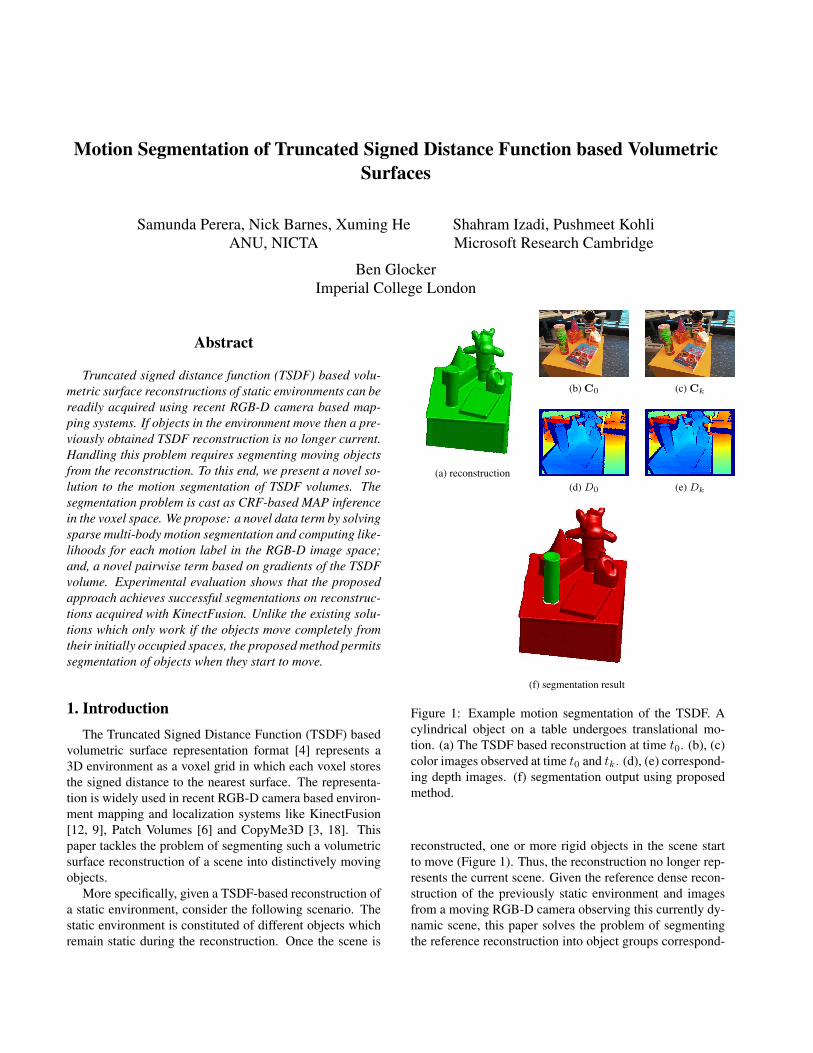
(a) reconstruction
(b) C0 (c) Ck
(d) D0 (e) Dk
(f) segmentation result
Figure 1: Example motion segmentation of the TSDF. Acylindrical object on a table undergoes translational mo-tion. (a) The TSDF based reconstruction at time t0. (b), (c)color images observed at time t0 and tk. (d), (e) correspond-ing depth images. (f) segmentation output using proposedmethod.
reconstructed, one or more rigid objects in the scene startto move (Figure 1). Thus, the reconstruction no longer rep-resents the current scene. Given the reference dense recon-struction of the previously static environment and imagesfrom a moving RGB-D camera observing this currently dy-namic scene, this paper solves the problem of segmentingthe reference reconstruction into object groups correspond-

ing to the moving objects and the background.Apart from the theoretical interest of segmenting TSDF
volumes, solving the above problem has important practi-cal applications. First of all, if moving objects can be seg-mented then they can be tracked over time and the recon-struction (both background and moving objects) can be con-tinuously updated over time by transforming the objects andintegrating new RGB-D data. For example, this would per-mit an area of the background that was earlier occluded byan object to be reconstructed. If moving objects are not han-dled and moving average based updates are used [12] thenreconstructed objects have to be discarded and mapping ar-tifcats can be observed. In addition, an automatic 3D objectsegmentation method would permit an autonomous robot tofirst reconstruct a scene using an RGB-D mapping systemand then to observe and segment objects that start to move.The fact that the 3D segmentations carry rich structure ofthe objects could be useful in helping the robot better han-dle the situation involved. Moreover, motion segmentationof reconstructions would permit a user to actively move anobject of interest to get a segmentation of it.
To this end we propose a novel method for motion seg-mentation of TSDF reconstructions. We cast the segmenta-tion as a CRF-based MAP inference problem in the voxelspace of the TSDF volume. By computing the motion ofeach moving object in the scene using sparse point tracksegmentation, we compute a unary likelihood/cost of as-signing a particular motion label to a pixel in an observedRGB-D image. This gives rise to a novel data term involv-ing the voxels. A novel pairwise term is constructed baseddirectly on the gradients of the TSDF volume. Unlike ex-isting approaches, this allows us to segment moving objectsthat move only slightly.
2. Related WorkMulti-body motion segmentation Existing work onmulti-body motion segmentation has been largely on 2D/3Dsparse point track segmentation [2] and on 2D/2.5D denseimage segmentation [16, 17]. The work is mainly based onmodel selection [5], affinity clustering [13] and subspaceclustering. Such work is useful for, but does not directlytackle dense segmentation of a 3D grid representation suchas a TSDF.
TSDF segmentation In [9], Izadi et al. describe anoccupancy-based approach to segment moving objects froma TSDF reconstruction. They first map a scene usingKinectFusion. A human user then moves an object in thescene that needs to be segmented, e.g. a tea pot resting ona table (Figure 2). When the object is moved from its ini-tial position to a new position, the initial position becomesunoccupied (free space). Izadi et al. use the camera poseobtained from KinectFusion along with the observed depth
images to detect these newly unoccupied voxels represent-ing the object. However, in order to correctly segment theobject, the object has to be moved completely from its ini-tially occupied space. If the object is only slightly or par-tially moved, the complete object cannot be extracted. Therecent work by Herbst et al. [7] on change detection basedsegmentation of maps created using PatchVolumes has thesame limitation. In contrast to these works, our method per-mits segmentation of objects when they start to move.
ray through a pixel
Figure 2: The object segmentation method of Izadi et al.[9]. The TSDF reconstruction represents a tea pot lyingon a plane. When the tea pot is removed from the scene,the camera gives depth measurements corresponding to theplane. Based on this voxels corresponding to the tea pot canbe identified.
The recent work by Ma and Sibley [11] solves motionbased object discovery, object detection, tracking and re-construction in an integrated system. Moving objects arediscovered by parts of the scene that fail to track with thedominant object model and each object is reconstructed inits own TSDF volume in an online fashion. Jacquet et al.[10] considers the problem of reconstructing multiple mov-ing objects in separate TSDF volumes allowing the volumesto interact with each other. While both [11] and [10] pro-vide a segmentation of an environment as multiple TSDFvolumes, they do not consider the segmentation of an exist-ing reconstruction into multiple moving objects. For exam-ple, if an object was stationary during the reconstruction andlater starts to move then unless the scene is reconstructedfrom scratch from all the pervious RGB-D images, [11] and[10] cannot segment the moving object from the reconstruc-tion.
3. Input and NotationThe input to the motion segmentation problem consists
of the TSDF reconstruction of the environment at time t0,the RGB-D images observed at time t0 and time tk (k > 0)as well as the pose of the camera at time t0. During time t0and tk, objects in the scene undergo rigid motion. Figure 1illustrates an example input to the problem.
Take any 3D Cartesian coordinate system attached to astatic point of the environment and denote it as the global

coordinate system g. Let p ∈ R3 be a point expressed inthis global coordinate system. Then the TSDF value at thepoint p is denoted by F (p). Let Γ ⊂ R3 be the continuousdomain in which the TSDF reconstruction is defined. TheTSDF reconstruction is discretized and made available asa set of voxels V . A fixed bijective mapping v : V → Γbetween the voxel elements and the points in the continuousdomain is given.
The depth and color images are denoted by D0, Dk andC0,Ck respectively. Note each image is indexed by thetime instant it was captured. Each depth image Dk and cor-responding color image Ck are assumed to be registeredwith each other. Dk and Ck are such that Dk : Ω → Rand Ck : Ω → R3 where Ω ⊂ R2 is the image pixel do-main. The set of pixels in an image is denoted by P . Afixed bijective mapping u : P → Ω between the pixel ele-ments and the continuous image pixel domain exists. Notethe 3D point cloud corresponding to the depth imageDk ex-pressed in the camera coordinate frame at time tk is givenby Xk(u) = Dk(u)K−1
[u 1
]Twhere K is the camera
intrinsic matrix.The pose of the camera at time t0 is denoted by Tg,0 ∈
SE(3). Here, Tg,0 is such that it transforms a point x0 ∈ R3
expressed in the camera coordinate frame at time t0 tothe global coordinate frame g according to the formula[xg 1
]T = Tg,0[x0 1
]Twhere xg is the coordinate of
the point expressed in the global coordinate frame.
4. Problem FormulationWhen objects move, the input TSDF reconstruction no
longer represents the current scene. Thus, using currentcamera pose, correspondences between the newly observedRGB-D measurement and the TSDF reconstruction canonly be established for the static part of the scene. There-fore, we compute the TSDF segmentation by computing thelikelihood for underlying motions in the RGB-D frame ob-served before motion by using a minimum of two frames.The problem is formulated as a CRF-based MAP inferenceproblem in the voxel grid space of the TSDF at the firstframe.
The voxels in the TSDF volume represent free space, re-constructed surfaces or the interior of surfaces. Let Λ ⊂ Vbe the set of voxels representing the reconstructed surfaces.Given a set of motion labels L, the task of segmenting theTSDF reconstruction involves assigning a label fp ∈ L toeach valid voxel p ∈ Λ. Let f denote a particular labelingassignment. Further, letE be a set of unordered pairs p, qof neighboring elements in Λ. Then using the pairwise CRFmodel, the MAP labeling f∗ is expressed
f∗ = argminf∈L|Λ|
∑p∈Λ
Dp(fp) +∑p,q∈E
Vp,q(fp, fq) (1)
where Dp(fp) = dfpp is the unary term (data term) and Vp,q
is the pairwise term.
4.1. Generating Label Space
As noted, during time t0 and tk, some of the objectsin the scene move. We determine the underlying motiongroups by segmenting sparse 3D point correspondences be-tween the RGB-D images at time t0 and tk. The sparsesegmentation is computed by applying RANSAC (using 3-point samples) in a greedy manner [19] to extract the Eu-clidean transformation of each motion group. Here, weadopt the triangle sampling based method proposed in [15]to improve the odds of a 3-point sample being an all inliersample. The segmentation is then refined using PEARL [5].
The output of sparse motion segmentation is the set ofmotion labels L = 1, . . . ,m present in the scene and aset Tl0,k ∈ SE(3)l∈L of motion parameters of each group.
The notation Tl0,k is as follows. Consider a point belong-ing to a motion group l. The point is observed by the cam-era at time t0 and tk giving 3D coordinate measurementsx0 ∈ R3 and xk ∈ R3 respectively. Here, the coordi-nates are expressed with respect to the camera coordinateframe at the respective time instants. Then Tl0,k is such that[x0 1
]T = Tl0,k[xk 1
]T.
Using similar notation, the Euclidean transformationwhich brings xk to the global coordinate frame is denotedby Tlg,k. It is straightforward to see that Tlg,k = Tg,0Tl0,k forall k. Note the relationship Tlg,0 = Tg,0 for all l ∈ L as thereconstruction represents the environment at time t0. Figure3 summarizes these Euclidean transformations for a scenewith two motion groups.
12
xg
x0 xk
reconstruction at time t0
observation at time t0 observation at time tk
g
Tg,0 Tg,0
T10,k
T20,k
T1g,k = Tg,0T1
0,k
Figure 3: Euclidean transformation notation for a scenewith two motion labels (L = 1, 2).

0
10
20
30
40
50
60
70
80
90
(a) R10
0
20
40
60
80
100
(b) R20 (c) d1
p (d) d2p (e) unary winner
Figure 4: Visualization of the data term. (a)-(b) image space unary costs. (c) cost for the motion label 1 (background motion).For voxels with no corresponding pixels, cost of c = 0 was used. (d) cost for the motion label 2 (motion of the cylinder) (e)per voxel winner (label corresponding to the minimum cost). Here, voxels having equal cost values in d1
p and d2p are shown
in blue color.
4.2. Data term
We construct the data term by computing unary costs forpixels in the RGB-D image space and associating them withcorresponding voxels (see Figure 4). Let Rlk(u) denote thecost of assigning a particular motion label l to a pixel u inthe RGB-D image at time tk. Further, define the functionwhich maps a pixel u in the RGB-D image at time tk to oneor more voxels in the TSDF reconstruction by
h(u, Dk, TLk(u)g,k ) : Ω×R× SE(3)→ P (2)
where Lk(u) ∈ L is the label of pixel u and P is the powerset of V , that is, the set of all possible subsets of V .
In order to obtain the voxels corresponding to a pixel inthe RGB-D image at time tk using the pixel to voxel map-ping function h, the transformation T
Lk(u)g,k should be se-
lected from the set T1g,k, . . . , T
mg,k. However, as Lk are
not known this cannot be performed for all but k = 0 1.At time t0 all motion groups have the same transformationTg,0 (Figure 3). Thus pixels corresponding to the RGB-Dimage at time t0 can be mapped to their corresponding vox-els. Based on this the data term is given by
dlp =
Rl0(u) p ∈ h(u, D0, Tg,0)c p /∈
⋃h(u, D0, Tg,0)u∈P
. (3)
Here, c is any finite constant cost assigned for voxels withno corresponding pixels. Figure 4 illustrates this data term.
4.2.1 Image Space Unary Cost Rl0
Using the Euclidean transformation Tl0,k, the point cloudcorresponding to the RGB-D image at time tk can be trans-
1If dense optical flow or per pixel tracking has been computed over allthe image frames then the pixels in an image at time tk can be associatedwith the pixels in the image at time t0. In this case, image space unarycosts can be mapped to the voxels using the camera pose Tg,0 at time t0.However, we do not compute such dense point correspondences.
formed to test the alignment with the point cloud corre-sponding to the RGB-D image at time t0. The error of thealignment is computed using 3D position, color and surfacenormal information, and stands as our image space unarycost term Rl0. Here, the point cloud Xk is first transformedinto time t0 by applying Tl0,k. The transformed point cloudis then used to obtain a synthesized depth image Dl
0 andcolor image Cl
0 using Z-buffering. The corresponding 3Dpoint cloud is given by Xl
0.
3D position alignment cost The 3D position alignmentcost is based on the distance between the correspondingpoints.
rl3D(u) = min(||X0(u)− Xl0(u)||, c1)/c1 (4)
Here, c1 > 0 is an upper bound (truncation value) on theposition alignment error.
Color compatibility cost The color compatibility ofthe alignment is computed based on normalized cross-correlation (NCC) between 3x3 image patches of C0 andCl
0, centered on corresponding pixels. The sum γ of NCCover all 3 color channels gives the color compatibility. Note−3 ≤ γ ≤ 3. This is converted to a cost term by
rlColor(u) = min(3− γ(C0, Cl0,u), c2)/c2 (5)
where 0 < c2 ≤ 6 is an upper bound.
Surface normal alignment cost The surface normalalignment cost is based on the angle difference between sur-face normals of the corresponding points. Let the unit sur-face normal maps for point clouds Xk and Xl
k be Nk andNlk respectively. Here, Nk : Ω → R3. Then the normal
alignment cost is given by
rlNormal(u) = min(arccos[N0(u) · Nl0(u)], c3)/c3 (6)
where 0 < c3 < 180. Here, the surface normal maps arecomputed using Plane PCA.
Combined alignment cost The 3D position alignmentcost, color compatibility cost and surface normal alignmentcost are aggregated to produce a combined alignment error
rl(u) =s1r
l3D(u) + s2r
lColor(u) + s3r
lNormal(u)
s1 + s2 + s3(7)
where s1, s2 and s3 are mixing coefficients that determinethe relative contribution of respective terms.
Background label unary cost attenuation Assumingmoving objects are spatially concentrated, we increase thepreference of pixels that are farther away from moving ob-jects to have the background motion label B. Let ρ(u) :Ω → R be a distance map indicating the 3D distance tothe nearest object feature point, identified using the sparsesegmentation result. Then the updated cost is given by
Rl0(u) =
exp(−0.5 ρ(u)2/σ2) rl(u) l = B
rl(u) otherwise. (8)
where σ is a parameter that depends on the spatial size ofthe objects being considered.
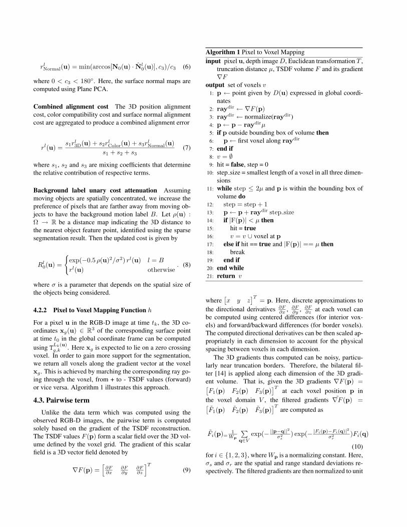
4.2.2 Pixel to Voxel Mapping Function h
For a pixel u in the RGB-D image at time tk, the 3D co-ordinates xg(u) ∈ R3 of the corresponding surface pointat time t0 in the global coordinate frame can be computedusing T
Lk(u)g,k . Here xg is expected to lie on a zero crossing
voxel. In order to gain more support for the segmentation,we return all voxels along the gradient vector at the voxelxg . This is achieved by marching the corresponding ray go-ing through the voxel, from + to - TSDF values (forward)or vice versa. Algorithm 1 illustrates this approach.
4.3. Pairwise term
Unlike the data term which was computed using theobserved RGB-D images, the pairwise term is computedsolely based on the gradient of the TSDF reconstruction.The TSDF values F (p) form a scalar field over the 3D vol-ume defined by the voxel grid. The gradient of this scalarfield is a 3D vector field denoted by
∇F (p) =[∂F∂x
∂F∂y
∂F∂z
]T(9)
Algorithm 1 Pixel to Voxel Mappinginput pixel u, depth imageD, Euclidean transformation T ,
truncation distance µ, TSDF volume F and its gradient∇F
output set of voxels v1: p ← point given by D(u) expressed in global coordi-
nates2: raydir ← ∇F (p)3: raydir ← normalize(raydir)4: p← p− raydirµ5: if p outside bounding box of volume then6: p← first voxel along raydir
7: end if8: v = ∅9: hit = false, step = 0
10: step size = smallest length of a voxel in all three dimen-sions
11: while step ≤ 2µ and p is within the bounding box ofvolume do
12: step = step + 113: p← p + raydir step size14: if |F(p)| < µ then15: hit = true16: v = v ∪ voxel at p17: else if hit == true and |F(p)| == µ then18: break19: end if20: end while21: return v
where[x y z
]T = p. Here, discrete approximations tothe directional derivatives ∂F
∂x , ∂F∂y , ∂F
∂z at each voxel canbe computed using centered differences (for interior vox-els) and forward/backward differences (for border voxels).The computed directional derivatives can be then scaled ap-propriately in each dimension to account for the physicalspacing between voxels in each dimension.
The 3D gradients thus computed can be noisy, particu-larly near truncation borders. Therefore, the bilateral fil-ter [14] is applied along each dimension of the 3D gradi-ent volume. That is, given the 3D gradients ∇F (p) =[F1(p) F2(p) F3(p)
]Tat each voxel position p in
the voxel domain V , the filtered gradients ∇F (p) =[F1(p) F2(p) F3(p)
]Tare computed as
Fi(p)=1Wp
∑q∈V
exp(− ||p−q||2σ2
s) exp(− |Fi(p)−Fi(q)|2
σ2r
)Fi(q)
(10)for i ∈ 1, 2, 3, whereWp is a normalizing constant. Here,σs and σr are the spatial and range standard deviations re-spectively. The filtered gradients are then normalized to unit

magnitude.
(a) (b)
Figure 5: Gradient of a 2D slice of the TSDF (a) The unitgradient vectors computed using finite differences repre-sented as arrows (b) The bilateral filtered output. The blackcurve shows the implicit surface.
Figure 5 illustrates the gradients computed for a 2D sliceof the TSDF volume along with the filtered result. As thegradient of a function is perpendicular to the level set ofthe function at the point, the gradient at the zero crossing(zero level) indicates the surface normal direction. The vox-els that lie along the surface normal direction exhibit simi-lar gradient directions. Based on the filtered gradients, thepairwise term of the segmentation cost function is thus con-structed as
Vp,q(fp, fq) = λ T(fp 6= fq) exp
(−θ2
p,q
2σ2θ
)(11)
where θp,q = arccos(|∇F (p) · ∇F (q)|
)and σθ is an in-
put parameter. T (·) is such that T (true) = 1 and T (false) =0. Note the pairwise term introduces a cost for neighbor-ing voxels with similar gradient direction to have differentlabels. λ is a scalar controlling the effect of the pairwiseterm.
5. Experimental Results and DiscussionThe proposed motion segmentation method was evalu-
ated using several TSDF based reconstructions obtained us-ing an implementation of the KinectFusion system. A 0.75m x 0.75 m x 0.75 m volume of an environment was recon-structed using a voxel grid with a resolution of 256 x 256x 256. The truncation parameters were set as c1 = 30mm,c2 = 5 and c3 = 45 and the mixing coefficients were setas s1 = 2, s2 = 4 and s3 = 1. The label corresponding tothe background motion (required in background unary costattenuation) was identified based on the largest depth rangeand the largest sparse feature point group. The parameter σwas computed using the maximum volume of the 3D con-vex hulls of the sparse feature points corresponding to eachobject motion group. If the maximum volume is v then σwas set to σ = 3v1/3. The data term was multiplied by 1000
and the pairwise term scale λ was set to 1e6. The pairwiseterm was computed using the 8-connectivity of voxels andσθ was set to 5. α-Expansion [1] was used to solve thesegmentation cost function.
Figure 6 shows the segmentation results for the examplesequence obtained. The cylinder was correctly segmentedfrom the planar table top. The figure also shows the segmen-tation result obtained using the existing method by Izadi etal [9]. As noted their method requires completely movingthe cylinder from its previously occupied position. How-ever, as the cylinder was only slightly moved (Figure 1),their method was unable to extract the complete object.
(a) proposed (b) existing
Figure 6: Segmentation results for the cylinder sequence.(a) the segmented cylinder removed to show the segmenta-tion boundary. (b) result using the existing method [9].
In another test data sequence, a tea pot and a mug wasslightly moved on a table. Figure 7 shows the results for thisTeaPotMug sequence. The segmentation of sparse featurepoints identified three motion groups corresponding to thetwo moving objects and the background. The unary costsobtained for each motion label were then used to segmentthe TSDF volume. The tea pot and mug were successfullysegmented from the table.
The CarJacket sequence features a toy car moving ontop of a jacket lying on the floor (Figure 8). Here, the goalof this experiment was to show that the proposed TSDFbased surface segmentation methodology is not limited tosegmenting objects lying on a plane. As expected, the pro-posed method could successfully segment the car from restof the scene.
We list numerical results on the segmentation accuracyof the proposed method in Table 1. Here the accuracy wascomputed by projecting the segmented volumes to manu-ally labeled depth images and counting the correctly labeledpixels (expressed as a percentage of the total number of pix-els). As noted, our method outperforms the existing methodin all three sequences. The table also gives the running timeresults of the α-expasion stage (Intel Core i7 1.6GHz CPU).
6. Conclusion and Future WorkIn this paper, we considered the problem of motion seg-
mentation of TSDF reconstructions. We proposed an au-

(a) reconstruction (b) C0 (c) C1
0
10
20
30
40
50
60
70
80
90
(d) R10
0
20
40
60
80
100
(e) R20
0
20
40
60
80
100
(f) R30
(g) (h)
Figure 7: TeaPotMug sequence and segmentation results. (a)-(c) input. (d)-(f) image space unary costs. (g), (h) segmentationresult using the proposed method.
tomatic method capable of successfully segmenting TSDFvolumes by constructing appropriate data and pairwiseterms. Existing TSDF based mapping systems either can-not handle the motion of objects which are already recon-structed, or cannot segment moving objects as and whenthey move. The TSDF segmentation method proposed inthis paper addresses these limitations. In future, we planto fully integrate the method with KinectFusion to update
Table 1: Quantitative results. segmentation accuracy ofIzadi et al. [9] and ours. |L| = #labels, |Λ| = #valid vox-els, |E| = #edges, time = running time of α-expasion stage.
Sequence |L| |Λ| |E| accuracy:[9]
accuracy:ours
time
Cylinder 2 1.3M 3.6M 94.94% 99.95% 2.37 sTeaPotMug 3 1.3M 3.7M 89.40% 99.79% 10.28 sCarJacket 2 1.3M 3.6M 97.67% 99.91% 2.35 s
the reconstruction with new data. Further, we plan to usecost volume filtering [8] for the inference stage to achieve afaster running time.
References[1] Y. Boykov, O. Veksler, and R. Zabih. Fast approximate en-
ergy minimization via graph cuts. Pattern Analysis and Ma-chine Intelligence, IEEE Trans., 23(11):1222–1239, 2001.
[2] T. Brox and J. Malik. Object segmentation by long termanalysis of point trajectories. In ECCV 2010, pages 282–295. Springer Berlin Heidelberg, 2010.
[3] E. Bylow, J. r. Sturm, C. Kerl, F. Kahl, and D. Cremers. Real-time camera tracking and 3d reconstruction using signed dis-
Acknowledgments: NICTA is funded by the Australian Governmentas represented by the Department of Broadband, Communications, and theDigital Economy, and the Australian Research Council (ARC) through theICT Centre of Excellence Program. This research was also supported inpart by ARC through its Special Research Initiative (SRI) in Bionic VisionScience and Technology grant to Bionic Vision Australia (BVA).

(a) reconstruction (b) C0 (c) C1
0
10
20
30
40
50
60
70
80
90
(d) R10
0
20
40
60
80
100
(e) R10 (f) (g)
Figure 8: Results for the CarJacket sequence. (a)-(c) input. (d), (e) image space unary costs. (f), (g) result using theproposed method.
tance functions. In Robotics: Science and Systems (RSS),Online Proceedings, volume 9, page 8, 2013.
[4] B. Curless and M. Levoy. A volumetric method for buildingcomplex models from range images. In Proceedings of the23rd annual conference on Computer graphics and interac-tive techniques, SIGGRAPH ’96, pages 303–312, New York,NY, USA, 1996. ACM.
[5] A. Delong, A. Osokin, H. Isack, and Y. Boykov. Fast approx-imate energy minimization with label costs. InternationalJournal of Computer Vision, 96(1):1–27, 2012.
[6] P. Henry, D. Fox, A. Bhowmik, and R. Mongia. Patch vol-umes: Segmentation-based consistent mapping with RGB-Dcameras. In 3D Vision, 2013 International Conference on,pages 398–405, June 2013.
[7] E. Herbst, P. Henry, and D. Fox. Toward online 3-d objectsegmentation and mapping. In IEEE ICRA, 2014.
[8] A. Hosni, C. Rhemann, M. Bleyer, C. Rother, andM. Gelautz. Fast cost-volume filtering for visual correspon-dence and beyond. Pattern Analysis and Machine Intelli-gence, IEEE Trans., 35(2):504–511, 2013.
[9] S. Izadi, D. Kim, O. Hilliges, D. Molyneaux, R. Newcombe,P. Kohli, J. Shotton, S. Hodges, D. Freeman, A. Davison, andA. Fitzgibbon. KinectFusion: Real-time 3d reconstructionand interaction using a moving depth camera. In Proceed-ings of the 24th Annual ACM Symposium on User InterfaceSoftware and Technology, UIST ’11, pages 559–568, NewYork, NY, USA, 2011. ACM.
[10] B. Jacquet, C. Hne, R. Angst, and M. Pollefeys. Multi-body depth-map fusion with non-intersection constraints. InECCV 2014, pages 735–750. Springer International Publish-ing, 2014.
[11] L. Ma and G. Sibley. Unsupervised dense object discovery,detection, tracking and reconstruction. In ECCV 2014, pages80–95. Springer International Publishing, 2014.
[12] R. A. Newcombe, S. Izadi, O. Hilliges, D. Molyneaux,D. Kim, A. J. Davison, P. Kohi, J. Shotton, S. Hodges, andA. Fitzgibbon. KinectFusion: Real-time dense surface map-ping and tracking. In ISMAR 2011, pages 127–136, Oct2011.
[13] P. Ochs and T. Brox. Higher order motion models and spec-tral clustering. In CVPR 2012, pages 614–621, June 2012.
[14] S. Paris and F. Durand. A fast approximation of the bilateralfilter using a signal processing approach. In ECCV 2006,pages 568–580. Springer Berlin Heidelberg, 2006.
[15] S. Perera and N. Barnes. Maximal cliques based rigid bodymotion segmentation with a RGB-D camera. In ACCV 2012,pages 120–133. Springer Berlin Heidelberg, 2013.
[16] A. Roussos, C. Russell, R. Garg, and L. Agapito. Densemultibody motion estimation and reconstruction from ahandheld camera. In ISMAR 2012, pages 31–40, Nov 2012.
[17] J. Stuckler and S. Behnke. Efficient dense 3d rigid-body mo-tion segmentation in RGB-D video. In BMVC. BMVA Press,2013.
[18] J. Sturm, E. Bylow, F. Kahl, and D. Cremers. CopyMe3D:Scanning and printing persons in 3d. In Pattern Recognition,volume 8142, pages 405–414. Springer Berlin Heidelberg,2013.
[19] P. H. S. Torr. Geometric motion segmentation and modelselection. Philosophical Transactions of the Royal Society ofLondon. Series A: Mathematical, Physical and EngineeringSciences, 356(1740):1321–1340, 1998.