most widely acceepted and trustedcdnassets.hw.net/eb/85/47bcbbe847ed91a009fae48dc7e8/esr... ·...
TRANSCRIPT

II
ICC-Especifrecomto any
Copy
“201(WS
Loo
0
000
ICC‐ECC‐ES | (800
ES Evaluationifically addressmmendation foy finding or ot
yright © 2015
14 Recipient oSSPC) Award i
k for the trus
ITW RE
ES Rep0) 423‐6587
n Reports are nsed, nor are th
or its use. Therher matter in t
5 ICC Evaluati
of Prestigiousin Excellence”
sted marks of
S
ED HEAD E
port | (562) 699
not to be consthey to be consre is no warranthis report, or a
on Service, LL
s Western Sta”
f Conformity
SEC
SECTION: 05
G
EPCON S7
‐0543 | ww
trued as represstrued as an enty by ICC Evaas to any produ
LC. All rights
ates Seismic P
!
DIVISION
CTION: 03 16
DIVISION
5 05 19—PO
RE
ITW
700 HIGHGLENDALE H
EVAL
7 ADHESIV
UNCRA
w.icc‐es.org
senting aestheendorsement ofaluation Servicuct covered by
reserved.
Policy Council
: 03 00 00—
6 00—CONC
N: 05 00 00
OST‐INSTALL
EPORT HOLD
W RED HE
H GROVE BOHEIGHTS, IL
UATION SU
VE ANCHO
ACKED CO
Most W
Thg
etics or any othf the subject ofce, LLC, exprethe report.
—CONCRETE
CRETE ANCH
—METALS
LED CONCR
DER:
EAD
OULEVARDLLINOIS 601
UBJECT:
ORING SY
ONCRETE
Widely Acce
his report is su
her attributes of the report oess or implied,
E
HORS
RETE ANCHO
139
YSTEM FO
A Subs
epted and
ESR‐Reissu
bject to renew
not r a as
ORS
OR CRACK
sidiary of
d Trusted
2308ued 05/2015wal 05/2016.
KED AND

ICC-ES Evaluation Reports are not to be construed as representing aesthetics or any other attributes not specifically addressed, nor are they to be construed as an endorsement of the subject of the report or a recommendation for its use. There is no warranty by ICC Evaluation Service, LLC, express or implied, as to any finding or other matter in this report, or as to any product covered by the report.
Copyright © 2015 ICC Evaluation Service, LLC. All rights reserved. Page 1 of 16 1000
ICC-ES Evaluation Report ESR-2308 Reissued May 2015 Revised November 2015
This report is subject to renewal May 2016.
www.icc-es.org | (800) 423-6587 | (562) 699-0543 A Subsidiary of the International Code Council ®
DIVISION: 03 00 00—CONCRETE Section: 03 16 00—Concrete Anchors DIVISION: 05 00 00—METALS Section: 05 05 19—Post-Installed Concrete Anchors REPORT HOLDER: ITW RED HEAD 700 HIGH GROVE BLVD GLENDALE HEIGHTS, ILLINOIS 60139 (800) 848-5611 www.itw-redhead.com [email protected] EVALUATION SUBJECT: ITW RED HEAD EPCON S7 ADHESIVE ANCHORING SYSTEM FOR CRACKED AND UNCRACKED CONCRETE 1.0 EVALUATION SCOPE
Compliance with the following codes:
2015, 2012, 2009, 2006 and 2003 International Building Code® (IBC)
2015, 2012, 2009, 2006 and 2003 International Residential Code® (IRC)
2013 Abu Dhabi International Building Code (ADIBC)† †The ADIBC is based on the 2009 IBC. 2009 IBC code sections referenced in this report are the same sections in the ADIBC.
Property evaluated:
Structural
2.0 USES
The Red Head Epcon S7 Adhesive Anchoring System is a post-installed anchorage system used to resist static, wind or earthquake (Seismic Design Categories A through F) tension and shear loads in cracked and uncracked normal-weight concrete having a specified compressive strength, f′c, of 2500 psi to 8,500 psi (17.2 MPa to 58.6 MPa) [minimum of 24 MPa is required under ADIBC Appendix L, Section 5.1.1].
The anchoring system complies with anchors as described in Section 1901.3 of the 2015 IBC, Section 1909 of the 2012 IBC and is an alternative to cast-in-place anchors described in Section 1908 of the 2012 IBC, and Sections 1911 and 1912 of the 2009 and 2006 IBC, and Sections 1912 and 1913 of the 2003 IBC. The anchoring
system may also be used where an engineered design is submitted in accordance with Section R301.1.3 of the IRC.
3.0 DESCRIPTION
3.1 General:
The Red Head Epcon S7 Adhesive Anchoring System is a two-component, high-strength, fast-cure, structural adhesive, used with continuously threaded rods and deformed reinforcing bar installed in normal-weight concrete. The primary components of the ITW Red Head Epcon S7 Adhesive Anchoring System are shown in Figure 1 of this report.
The manufacturer’s printed installation instructions (MPII) are included with the adhesive packaging and are replicated in Figure 3 of this report.
3.2 Materials:
3.2.1 Adhesive: The Red Head Epcon S7 Anchoring System is a two-part hybrid epoxy packaged in a dual-chamber cartridge at a volumetric ratio of 10:1. The cartridge is available in 28-ounce (side-by-side) and 10-ounce (coaxial) sizes. The components are dispensed through a static mixing nozzle which attaches to the cartridge. The original, unopened cartridge has a shelf life of 15 months, as indicated by the “best used by” date stamped onto the cartridge, when stored in a cool, dry, ventilated area and in accordance with Figure 3.
3.2.2 Hole Cleaning Equipment: Hole cleaning equipment consists of wire brushes, as shown in Figures 1 and 3, and a compressed air nozzle with extension.
3.2.3 Dispensing Tools: Red Head Epcon S7 Adhesive must be dispensed with manual or pneumatic dispensing tools provided by ITW Red Head, as shown in Figure 1.
3.2.4 Anchor Elements:
3.2.4.1 Threaded Rods: The continuously threaded rods range from 3/8 inch through 11/4 inches (9.5 mm through 31.75 mm) in diameter. Carbon steel threaded rods must comply with either ASTM A36 [minimum futa = 58,000 psi (400 MPa)] or ASTM A193, Grade B7 [minimum futa = 125,000 psi (860 MPa)]. Stainless steel threaded rods must comply with ASTM F593 (Alloy Type 300, CW1 and CW2) [minimum futa = 95,000 psi (655 MPa) for CW1, and futa =80,000 psi (552 MPa) for CW2 ]. Table 1 notes steel design information for the threaded rods. Carbon steel threaded rods must be furnished with a minimum 0.0002-inch-thick (5 m) zinc electroplated coating complying with ASTM B633 SC1 or must be hot-dipped galvanized complying with ASTM A153, Class C or D.

ESR-2308 | Most Widely Accepted and Trusted Page 2 of 16
Threaded steel rods must be straight and free from indentations or other defects along their length.
3.2.4.2 Steel Reinforcing Bars: Steel reinforcing bars are deformed reinforcing bars as described in Table 4 of this report. The embedded portions of reinforcing bars must be straight, and free of mill scale, rust, mud, oil, and other coatings that may impair the bond with the adhesive. Reinforcing bars must not be bent after installation, except as set forth in ACI 318-14 Section 26.6.3.1 (b) or ACI 318-11 Section 7.3.2, as applicable, with the additional condition that the bars must be bent cold, and heating of reinforcing bars to facilitate field bending is not permitted.
3.2.4.3 Ductility: In accordance with ACI 318-14 2.3 or ACI 318-11 D.1, as applicable, in order for a steel element to be considered ductile, the tested elongation must be at least 14 percent and reduction of area must be at least 30 percent. Steel elements with a tested elongation of less than 14 percent or a reduction of area of less than 30 percent, or both, are considered brittle. Where values are nonconforming or unstated, the steel must be considered brittle.
3.3 Concrete:
Normal-weight concrete must comply with Sections 1903 and 1905 of the IBC. The specified compressive strength of the concrete must be from 2,500 psi to 8,500 psi (17.2 MPa to 58.6 MPa) [minimum of 24 MPa is required under ADIBC Appendix L, Section 5.1.1].
4.0 DESIGN AND INSTALLATION
4.1 Strength Design:
4.1.1 General: The design strength of anchors under the 2015 IBC, as well as the 2015 IRC must be determined in accordance with ACI 318-14 and this report. The design strength of anchors under the 2012, 2009, 2006 and 2003 IBC, as well as the 2012, 2009, 2006 and 2003 IRC, must be determined in accordance with ACI 318-11and this report.
A design example in accordance with the 2012 IBC based on ACI 318-11 is provided in Figure 2 of this report.
Design parameters are based on ACI 318-14 for use with the 2015 IBC, and the ACI 318-11 for use with the 2012, 2009, 2006 and 2003 IBC unless noted otherwise in this report.
The strength design of anchors must comply with ACI 318-14 17.3.1 or ACI 318-11 D.4.1, as applicable, except as required in ACI 318-14 17.2.3 or ACI 318-11 D.3.3, as applicable. Design parameters are provided in Tables 1 through 6. Strength reduction factors, , as given in ACI 318-14 17.3.3 or ACI 318-11 D.4.3, as applicable, must be used for load combinations calculated in accordance with Section 1605.2 of the IBC or ACI 318-14 5.3 or ACI 318-11 9.2, as applicable. Strength reduction factors, , as described in ACI 318-11 D.4.4, must be used for load combinations calculated in accordance with ACI 318-11 Appendix C.
4.1.2 Static Steel Strength in Tension: The nominal static steel strength of a single anchor in tension, Nsa, in accordance with ACI 318-14 17.4.1.2 or ACI 318-11 D.5.1.2, as applicable, and the associated strength reduction factors, , in accordance with ACI 318-14 17.3.3 or ACI 318-11 D.4.3, as applicable, are given in Tables 1 and 4 of this report for the anchor element types included in this report.
4.1.3 Static Concrete Breakout Strength in Tension: The nominal static concrete breakout strength of a single anchor or group of anchors in tension, Ncb or Ncbg, must be
calculated in accordance with ACI 318-14 17.4.2 or ACI 318-11 D.5.2, as applicable, with the following addition:
The basic concrete breakout strength of a single anchor in tension, Nb, must be calculated in accordance with ACI 318-14 17.4.2.2 or ACI 318-11 D.5.2.2, as applicable, using the values of kc,cr, and kc,uncr as described in Tables 2 and 5 of this report. Where analysis indicates no cracking in accordance with ACI 318-14 17.4.2.6 or ACI 318-11 D.5.2.6, as applicable, Nb must be calculated using kc,uncr and Ψc,N = 1.0. For anchors in lightweight concrete see ACI 318-14 17.2.6 or ACI 318-11 D.3.6, as applicable. The value of f′c used for calculation must be limited to 8,000 psi (55 MPa) in accordance with ACI 318-14 17.2.7 or ACI 318-11 D.3.7, as applicable. Additional information for the determination of nominal bond strength in tension is given in Section 4.1.4 of this report.
4.1.4 Static Bond Strength in Tension: The nominal static bond strength of a single adhesive anchor or group of adhesive anchors in tension, Na or Nag, must be calculated in accordance with ACI 318-14 17.4.5 or ACI 318-11 D.5.5, as applicable. Bond strength values are a function of whether the concrete is cracked or uncracked, the concrete temperature range, the installation conditions (dry or water-saturated concrete, water-filled holes, or submerged), and the level of inspection provided. The resulting characteristic bond strength shall be multiplied by the associated strength reduction factor nn as follows:
CONCRETE TYPE
PERMISSIBLE INSTALLATION CONDITIONS
BOND STRENGTH
ASSOCIATED STRENGTH REDUCTION
FACTOR
Uncracked
Dry uncr d
Water-saturated uncr ws
Water-filled holes uncr wf
Submerged uncr sub
Cracked
Dry cr d
Water-saturated cr ws
Water-filled holes cr wf
Submerged cr sub
Strength reduction factors for determination of the bond strength are given in Tables 3 and 6 of this report.
4.1.5 Static Steel Strength in Shear: The nominal static strength of a single anchor in shear as governed by the steel, , in accordance with ACI 318-14 17.5.1.2 or ACI 318-11 D.6.1.2, as applicable, and strength reduction factors, , in accordance with ACI 318-14 17.2.3 or ACI 318-11 D.4.3, as applicable are given in Tables 1 and 4 of this report for the anchor element types included in this report.
4.1.6 Static Concrete Breakout Strength in Shear: The nominal concrete breakout strength of a single anchor or group of anchors in shear, Vcb or Vcbg, must be calculated in accordance with ACI 318-14 17.5.2 or ACI 318-11 D.6.2, as applicable, based on information given in Table 2 and Table 5 of this report. The basic concrete breakout strength of a single anchor in shear, Vb, must be calculated in accordance with ACI 318-14 17.5.2.2 or ACI 318-11 D.6.2.2, as applicable, using the values of d given in this report in lieu of da (2015, 2012 and 2009 IBC), do (2006 IBC). In addition, hef shall be substituted for ℓe. In no case shall ℓe exceed 8d. The value of f′c must be limited to a
ESR-2308 | Most Widely Accepted and Trusted Page 3 of 16
maximum value of 8,000 psi (55 MPa) in accordance with ACI 318-14 17.2.7 or ACI 318-11 D.3.7, as applicable.
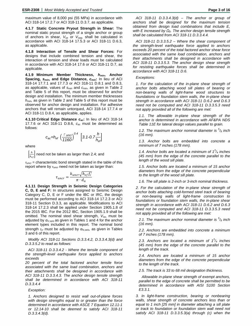
4.1.7 Static Concrete Pryout Strength in Shear: The nominal static pryout strength of a single anchor or group of anchors in shear, Vcp or Vcpg, shall be calculated in accordance with ACI 318-14 17.5.3 or ACI 318-11 D.6.3, as applicable.
4.1.8 Interaction of Tensile and Shear Forces: For designs that include combined tension and shear, the interaction of tension and shear loads must be calculated in accordance with ACI 318-14 17.6 or ACI 318-11 D.7, as applicable.
4.1.9 Minimum Member Thickness, hmin, Anchor Spacing, smin, and Edge Distance, cmin: In lieu of ACI 318-14 17.7.1 and 17.7.3 or ACI 318-11 D.8.1 and D.8.3, as applicable, values of smin and cmin, as given in Table 2 and Table 5 of this report, must be observed for anchor design and installation. The minimum member thicknesses hmin, as given in Table 2 and Table 5 of this report must be observed for anchor design and installation. For adhesive anchors that will remain untorqued, ACI 318-14 17.7.4 or ACI 318-11 D.8.4, as applicable, applies.
4.1.10 Critical Edge Distance cac: In lieu of ACI 318-14 17.7.6 or ACI 318-11 D.8.6, cac must be determined as follows:
cac=hef·τuncr
1160
0.4· 3.1-0.7
h
hef
where
need not be taken as larger than 2.4; and
τuncr = characteristic bond strength stated in the table of this report where by τuncr need not be taken as larger than:
∙
4.1.11 Design Strength in Seismic Design Categories C, D, E and F: In structures assigned to Seismic Design Category C, D, E or F under the IBC or IRC, the design must be performed according to ACI 318-14 17.2.3 or ACI 318-11 Section D.3.3, as applicable. Modifications to ACI 318-14 17.2.3 shall be applied under Section 1905.1.8 of the 2015 IBC. For the 2012 IBC, Section 1905.1.9 shall be omitted. The nominal steel shear strength, Vsa, must be adjusted by αV,seis as given in Tables 1 and 4 for the anchor element types included in this report. The nominal bond strengthcr must be adjusted by αN,seis, as given in Tables 3 and 6 of this report.
Modify ACI 318-11 Sections D.3.3.4.2, D.3.3.4.3(d) and D.3.3.5.2 to read as follows:
ACI 318-11 D.3.3.4.2 - Where the tensile component of the strength-level earthquake force applied to anchors exceeds 20 percent of the total factored anchor tensile force associated with the same load combination, anchors and their attachments shall be designed in accordance with ACI 318-11 D.3.3.4.3. The anchor design tensile strength shall be determined in accordance with ACI 318-11 D.3.3.4.4
Exception:
1. Anchors designed to resist wall out-of-plane forces with design strengths equal to or greater than the force determined in accordance with ASCE 7 Equation 12.11-1 or 12.14-10 shall be deemed to satisfy ACI 318-11 D.3.3.4.3(d).
ACI 318-11 D.3.3.4.3(d) – The anchor or group of anchors shall be designed for the maximum tension obtained from design load combinations that include E, with E increased by Ω0. The anchor design tensile strength shall be calculated from ACI 318-11 D.3.3.4.4.
ACI 318-11 D.3.3.5.2 – Where the shear component of the strength-level earthquake force applied to anchors exceeds 20 percent of the total factored anchor shear force associated with the same load combination, anchors and their attachments shall be designed in accordance with ACI 318-11 D.3.3.5.3. The anchor design shear strength for resisting earthquake forces shall be determined in accordance with ACI 318-11 D.6.
Exceptions:
1. For the calculation of the in-plane shear strength of anchor bolts attaching wood sill plates of bearing or non-bearing walls of light-frame wood structures to foundations or foundation stem walls, the in-plane shear strength in accordance with ACI 318-11 D.6.2 and D.6.3 need not be computed and ACI 318-11 D.3.3.5.3 need not apply provided all of the following are met:
1.1. The allowable in-plane shear strength of the anchor is determined in accordance with AF&PA NDS Table 11E for lateral design values parallel to grain.
1.2. The maximum anchor nominal diameter is 5/8 inch (16 mm).
1.3. Anchor bolts are embedded into concrete a minimum of 7 inches (178 mm).
1.4. Anchor bolts are located a minimum of 13/4 inches (45 mm) from the edge of the concrete parallel to the length of the wood sill plate.
1.5. Anchor bolts are located a minimum of 15 anchor diameters from the edge of the concrete perpendicular to the length of the wood sill plate.
1.6. The sill plate is 2-inch or 3-inch nominal thickness.
2. For the calculation of the in-plane shear strength of anchor bolts attaching cold-formed steel track of bearing or non-bearing walls of light-frame construction to foundations or foundation stem walls, the in-plane shear strength in accordance with ACI 318-11 D.6.2 and D.6.3 need not be computed and ACI 318-11 D.3.3.5.3 need not apply provided all of the following are met:
2.1. The maximum anchor nominal diameter is 5/8 inch (16 mm).
2.2. Anchors are embedded into concrete a minimum of 7 inches (178 mm).
2.3. Anchors are located a minimum of 13/4 inches (45 mm) from the edge of the concrete parallel to the length of the track.
2.4. Anchors are located a minimum of 15 anchor diameters from the edge of the concrete perpendicular to the length of the track.
2.5. The track is 33 to 68 mil designation thickness.
Allowable in-plane shear strength of exempt anchors, parallel to the edge of concrete shall be permitted to be determined in accordance with AISI S100 Section E3.3.1.
3. In light-frame construction, bearing or nonbearing walls, shear strength of concrete anchors less than or equal to 1 inch [25 mm] in diameter attaching a sill plate or track to foundation or foundation stem wall need not satisfy ACI 318-11 D.3.3.5.3(a) through (c) when the

ESR-2308 | Most Widely Accepted and Trusted Page 4 of 16
design strength of the anchors is determined in accordance with ACI 318-11 D.6.2.1(c).
4.2 Allowable Stress Design:
4.2.1 General: For anchors designed using load combinations in accordance with IBC Section 1605.3 (Allowable Stress Design), allowable loads shall be established using Eq. (4-2) or Eq. (4-3):
,
Eq. (4-2)
and
,
Eq. (4-3)
where
Tallowable,ASD = Allowable tension load (lbf or kN)
Vallowable,ASD = Allowable shear load (lbf or kN)
Nn = Lowest design strength of an anchor or anchor group in tension as determined in accordance with ACI 318-14 Chapter 17 and 2015 IBC Section 1905.1.8, ACI 318-11 Appendix D, ACI 318-08 Appendix D and 2009 IBC Sections 1908.1.9 and 1908.1.10, ACI 318-05 Appendix D and 2006 IBC Section 1908.1.16, and Section 4.1 of this report, as applicable.
Vn = Lowest design strength of an anchor or anchor group in shear as determined in accordance with ACI 318-14 Chapter 17 and 2015 IBC Section 1905.1.8, ACI 318-11 Appendix D, ACI 318-08 Appendix D and 2009 IBC Sections 1908.1.9 and 1908.1.10, ACI 318-05 Appendix D and 2006 IBC Section 1908.1.16, and Section 4.1 of this report, as applicable.
= Conversion factor calculated as a weighted average of the load factors for the controlling load combination. In addition, must include all applicable factors to account for non-ductile failure modes and required over-strength.
Limits on edge distance, anchor spacing and member thickness described in this report must apply.
Example calculations for derivation of Tallowable,ASD are provided in Figure 2 and Table 7.
4.2.2 Interaction of tensile and shear forces: In lieu of ACI 318-14 17.6.1, 17.6.2 and 17.6.3 or ACI 318-11 D.7.1, D.7.2 and D.7.3, as applicable, interaction must be calculated as follows:
For shear loads V ≤ 0.2Vallowable,ASD, the full allowable load in tension shall be permitted.
For tension loads T ≤ 0.2Tallowable,ASD, the full allowable load in shear shall be permitted.
For all other cases:
,
, 1.2 Eq. (4-4)
4.3 Installation:
Installation parameters are illustrated in Figure 3 of this report. Installation must be in accordance with ACI 318-14 17.8.1 and 17.8.2 or ACI 318-11 D.9.1 and D.9.2, as applicable. Anchor locations must comply with this report and the plans and specifications approved by the code official. Installation of the Red Head Epcon S7 Adhesive Anchor System must conform to the manufacturer’s printed installation instructions included in each unit package, as provided in Figure 3 of this report.
The adhesive anchoring system may be used for floor (vertically down), wall (horizontal) and overhead applications. Overhead applications are limited to use with
the 3/8-inch- (9.5 mm) through 1/2-inch-diameter (12 mm) threaded rods and reinforcing bars, assembled with a Red Head hole plug. Horizontal applications installed at a concrete or adhesive temperature above 70°F (21°C) require the use of a Red Head hole plug with the threaded rod or reinforcing bar.
4.4 Special Inspection:
4.4.1 General: Installations may be made under continuous special inspection or periodic special inspection, as determined by the registered design professional. Table 3 and Table 6 of this report provide strength reduction factors, , corresponding to the type of inspection provided.
Continuous special inspection of adhesive anchors installed in horizontal or upwardly inclined orientations to resist sustained tension loads shall be performed in accordance with ACI 318-14 17.8.2.4 or ACI 318-11 D.9.2.4, as applicable.
Under the IBC, additional requirements as set forth in Section 1705.1.1 and Table 1705.3 of the 2015 or 2012 IBC, and Sections 1705, 1706 or 1707 of the 2009, 2006, and 2003 IBC must be observed, where applicable.
4.4.2 Continuous Special Inspection: Installations made under continuous special inspection with an on-site proof loading program must be performed in accordance with Section 1705.1.1 and Table 1705.3 of the 2015 and 2012 IBC, Sections 1704.4 and 1704.15 of the 2009 IBC, or Section 1704.13 of the 2006 and 2003 IBC, whereby continuous special inspection is defined in Section 1702.1 of the IBC, and this report. The special inspector must be on the jobsite continuously during anchor installation to verify anchor type, adhesive expiration date, anchor dimensions, concrete type, concrete compressive strength, hole dimensions, hole cleaning procedures, anchor spacing, edge distances, concrete thickness, anchor embedment, tightening torque, and adherence to the manufacturers printed installation instructions.
The proof loading program must be established by the registered design professional. As a minimum, the following requirements must be addressed in the proof loading program:
1. Frequency of proof loading based on anchor type, diameter, and embedment.
2. Proof loads by anchor type, diameter, embedment, and location.
3. Acceptable displacements at proof load.
4. Remedial action in the event of a failure to achieve proof load, or excessive displacement.
Unless otherwise directed by the registered design professional, proof loads must be applied as confined tension tests. Proof load levels must not exceed the lesser of 50 percent of expected peak load based on adhesive bond strength, or 80 percent of the anchor yield strength. The proof load shall be maintained at the required load level for a minimum of 10 seconds.
4.4.3 Periodic Special Inspection: Periodic special inspection must be performed where required in accordance with Section 1705.1.1 and Table 1705.3 of the 2015 and 2012 IBC, Section 1704.15 and Table 1704.4 of the 2009 IBC, or Section 1704.13 of the 2006, and 2003 IBC, whereby periodic special inspection is defined in Section 1702.1 of the IBC and this report. The special inspector must be on the jobsite initially during anchor installation to verify anchor type, anchor dimensions, concrete type, concrete compressive strength, hole
ESR-2308 | Most Widely Accepted and Trusted Page 5 of 16
dimensions, hole cleaning procedures, anchor spacing, edge distances, concrete thickness, anchor embedment, tightening torque, and adherence to the manufacturer’s printed installation instructions. The special inspector must verify the initial installations of each type and size of adhesive anchor by construction personnel on the site. Subsequent installations of the same anchor type and size by the same construction personnel are permitted to be performed in the absence of the special inspector. Any change in the anchor product being installed or the personnel performing the installation requires an initial inspection. For ongoing installations over an extended period, the special inspector must make regular inspections to confirm correct handling and installation of the product.
4.5 Compliance with NSF/ANSI Standard 61:
The Epcon S7 Adhesive Anchor System complies with the requirements of NSF/ANSI Standard 61, as referenced in Section 605 of the 2009 and 2006 International Plumbing Code® (IPC), and is certified for use as an anchoring adhesive for installing threaded rods less than or equal to 1.3 inches (33 mm) in diameter in concrete for water treatment applications. An NSF/ANSI Standard 61 listing is provided by NSF International.
5.0 CONDITIONS OF USE
The Red Head Epcon S7 Adhesive Anchoring System described in this report complies with or is a suitable alternative to what is specified in, those codes listed in Section 1.0 of this report, subject to the following conditions:
5.1 The Red Head Epcon S7 Adhesive must be installed in accordance with the manufacturer’s printed installation instructions, as included with the adhesive packaging and reproduced in Figure 3 of this report.
5.2 The anchors must be installed in cracked and uncracked normal-weight concrete having a specified compressive strength of f′c = 2,500 psi to 8,500 psi (17.2 MPa to 58.6 MPa) [minimum of 24 MPa is required under ADIBC Appendix L, Section 5.1.1].
5.3 The values of f′c used for calculation purposes must not exceed 8,000 psi (55 MPa).
5.4 Anchors must be installed in concrete base materials in holes predrilled in accordance with the instructions provided in Figure 3 of this report, using a carbide-tipped masonry drill bit manufactured within the range of the maximum and minimum drill-tip dimensions of ANSI B212.15-1994.
5.5 Loads applied to the anchors must be adjusted in accordance with Section 1605.2 of the IBC for strength design and in accordance with Section 1605.3 of the IBC for allowable stress design.
5.6 Red Head Epcon S7 Adhesive Anchors are recognized for use in resisting short- and long-term loads, including wind and earthquake loads, subject to the conditions of this report.
5.7 In structures assigned to Seismic Design Category C, D, E or F under the IBC or IRC, anchor strength must comply with the requirements of 2009 IBC Section 1908.1.9 or 2006 IBC Section 1908.1.16
5.8 Epcon S7 adhesive anchors are permitted to be installed in concrete that is cracked or that may be expected to crack during the service life of the anchor, subject to the conditions of this report.
5.9 Strength design values must be established in accordance with Section 4.1 of this report.
5.10 Allowable stress design values must be established in accordance with Section 4.2 of this report.
5.11 Minimum anchor spacing and edge distance, as well as minimum member thickness, must comply with the values given in this report.
5.12 Prior to anchor installation, calculations and details demonstrating compliance with this report must be submitted to the code official. The calculations and details must be prepared by a registered design professional where required by the statutes of the jurisdiction in which the project is to be constructed.
5.13 Anchors are not permitted to support fire-resistive construction. Where not otherwise prohibited by the code, anchors are permitted for installation in fire-resistive construction provided at least one of the following conditions is fulfilled:
Anchors are used to resist wind or seismic forces only.
Anchors that support gravity load–bearing structural elements are within a fire-resistive envelope or a fire-resistive membrane, are protected by approved fire-resistive materials, or have been evaluated for resistance to fire exposure in accordance with recognized standards.
Anchors are used to support nonstructural elements.
5.14 Since an ICC-ES acceptance criteria for evaluating data to determine the performance of adhesive anchors subjected to fatigue or shock loading is unavailable at this time, the use of these anchors under such conditions is beyond the scope of this report.
5.15 Use of zinc-plated carbon steel threaded rods or steel reinforcing bars is limited to dry, interior locations.
5.16 Use of hot-dipped galvanized carbon steel rods and stainless steel rods is permitted for exterior exposure or damp environments.
5.17 Steel anchoring materials in contact with preservative-treated and fire-retardant-treated wood must be of zinc-coated carbon steel or stainless steel. The minimum coating weights for zinc-coated steel must comply with ASTM A153.
5.18 Special inspection must be provided in accordance with Section 4.4 of this report. Continuous special inspection for anchors installed in horizontal or upwardly inclined orientations to resist sustained tension loads must be provided in accordance with Section 4.4 of this report.
5.19 Installation of anchors in horizontal or upwardly inclined orientations to resist sustained tension loads shall be performed by personnel certified by an applicable certification program in accordance with ACI 318-14 17.8.2.2 or 17.8.2.3; or ACI 318-11 D.9.2.2 or D.9.2.3, as applicable.
5.20 Red Head Epcon S7 Adhesive Anchors may be used to resist tension and shear forces in wall, floor and overhead installations only if installation is into concrete with a temperature between 14°F and 110°F. Overhead applications are limited to use with 3/8-inch- through 1/2-inch-diameter (9.5 mm through

ESR-2308 | Most Widely Accepted and Trusted Page 6 of 16
12 mm) threaded rods and reinforcing bars, assembled with a Red Head hole plug. Horizontal applications installed at a concrete temperature above 70°F (21°C) require the use of a Red Head hole plug with the threaded rod or reinforcing bar. See the MPII in Figure 3 of this report for temperature and installation requirements.
5.21 Anchors shall not be used for applications where the concrete temperature can rise from 40°F (or less) to 80°F (or higher) within a 12-hour period. Such applications may include but are not limited to anchorage of building facade systems and other applications subject to direct sun exposure.
5.22 Red Head Epcon S7 Adhesive is manufactured in the U.S.A. under a quality-control program with inspections by ICC-ES.
6.0 EVIDENCE SUBMITTED
Data in accordance with the ICC-ES Acceptance Criteria for Post-installed Adhesive Anchors in Concrete Elements (AC308), dated June 2015, which incorporates requirements in ACI 355.4-11.
7.0 IDENTIFICATION
Red Head Epcon S7 Adhesive is identified by labels on the adhesive cartridges bearing the adhesive manufacturer’s name (ITW Commercial Construction North America) and address (Glendale Heights, Illinois), the product name (Red Head Epcon S7), best-used-by expiration date, and the evaluation report number (ESR-2308).

ESR-2308 | Most Widely Accepted and Trusted Page 7 of 16
TABLE 1—STEEL DESIGN INFORMATION FOR U.S. CUSTOMARY UNIT THREADED ROD (1)
CHARACTERISTIC SYMBOL UNITS NOMINAL ROD DIAMETER (inch)
3/8 1/2
5/8 3/4
7/8 1 11/4
Threaded rod effective cross-sectional area
Ase inch² 0.078 0.142 0.226 0.335 0.462 0.606 0.969
Car
bo
n S
teel
A36
Nominal steel strength in tension
Nsa lb 4,500 8,230 13,110 19,400 26,780 35,130 56,210
Nominal steel strength in shear Vsa lb 2,250 4,940 7,870 11,640 16,070 21,080 33,730
Strength reduction factor for tension, steel failure mode - 0.75 0.75 0.75 0.75 0.75 0.75 0.75
Strength reduction factor for shear, steel failure mode1 - 0.65 0.65 0.65 0.65 0.65 0.65 0.65
Reduction factor for seismic
shear V,seis - 0.70 0.70 0.70 0.70 0.70 0.70 0.70
Car
bo
n S
teel
A19
3 B
7
Nominal steel strength in tension
Nsa lb 9,690 17,740 28,250 41,810 57,710 75,710 121,140
Nominal steel strength in shear Vsa lb 4,845 10,640 16,950 25,090 34,630 45,430 72,680
Strength reduction factor for tension, steel failure mode - 0.75 0.75 0.75 0.75 0.75 0.75 0.75
Strength reduction factor for shear, steel failure mode1 - 0.65 0.65 0.65 0.65 0.65 0.65 0.65
Reduction factor for seismic shear V,seis - 0.70 0.70 0.70 0.70 0.70 0.70 0.70
Sta
inle
ss S
teel
F59
3
F593 CW1 nominal steel strength in tension
Nsa lb 7,365 13,480 21,470 - - - -
F593 CW1 nominal steel strength in shear
Vsa lb 3,680 6,740 10,735 - - - -
F593 CW2 nominal steel strength in tension
Nsa lb - - - 25,385 35,110 46,055 73,645
F593 CW2 nominal steel strength in shear
Vsa lb - - - 12,690 17,555 23,030 36,820
Strength reduction factor for tension, steel failure mode1 - 0.65 0.65 0.65 0.65 0.65 0.65 0.65
Strength reduction factor for shear, steel failure mode - 0.60 0.60 0.60 0.60 0.60 0.60 0.60
Reduction factor for seismic
shear V,seis - 0.70 0.70 0.70 0.70 0.70 0.70 0.70
For SI: 1 inch = 25.4mm, 1 lbf = 4.45N, 1ft-lbf = 1.356 N-M, 1 psi = 0.006895 MPa. 1The tabulated value of applies when the load combinations of Section 1605.2 of the IBC, ACI 318-14 5.3 or ACI 318-11 9.2 are used. If the load combinations of ACI 318-11 Appendix C are used, the appropriate value of must be determined in accordance with ACI 318-11 D.4.4.

ESR-2308 | Most Widely Accepted and Trusted Page 8 of 16
TABLE 2—CONCRETE BREAKOUT DESIGN INFORMATION FOR U.S. CUSTOMARY UNIT THREADED ROD (1)
CHARACTERISTIC SYMBOL UNITS NOMINAL ROD DIAMETER (inch)
3/8 1/2
5/8 3/4
7/8 1 11/4
Effectiveness factor for uncracked concrete
kuncr - 24 24 24 24 24 24 24
Effectiveness factor for cracked concrete
kcr - 17 17 17 17 17 17 17
Minimum concrete thickness hmin in. hef + 11/4 hef + 2do
Anchor embedment depth - minimum hef,min in. 23/8 23/4 31/8 31/2 31/2 4 5
Minimum spacing smin in. 15/16 11/2 21/2 3 31/2 4 5
Minimum edge distance cmin in. 15/16 11/2 21/2 3 31/2 4 5
Critical edge distance cac in. See Section 4.1.10 of this report
Strength reduction factor for tension, concrete failure mode1 Cond.
B 0.65 0.65 0.65 0.65 0.65 0.65 0.65
Strength reduction factor for shear, concrete failure mode1
Cond. B
0.70 0.70 0.70 0.70 0.70 0.70 0.70
For SI: 1 inch = 25.4mm, 1 lbf = 4.45N, 1ft-lbf = 1.356 N-M, 1 psi = 0.006895 MPa. 1The tabulated value of applies when the load combinations of Section 1605.2 of the IBC, ACI 318-14 5.3 or ACI 318-11 9.2 are used and the requirements of ACI 318-14 17.3.3 or ACI 318-11 D.4.3, as applicable, for Condition B are met. If the load combinations of ACI 318-11 Appendix C are used, the appropriate value of must be determined in accordance with ACI 318-11 D.4.4 for Condition B.

ESR-2308 | Most Widely Accepted and Trusted Page 9 of 16
TABLE 3—RED HEAD EPCON S7 ADHESIVE ANCHOR BOND STRENGTH DESIGN INFORMATION FOR U.S. CUSTOMARY UNIT THREADED ROD (1,5)
CHARACTERISTIC SYMBOL UNITS NOMINAL ROD DIAMETER (inch)
3/8 1/2
5/8 3/4
7/8 1 11/4
Anchor embedment depth - minimum hef in. 23/8 23/4 31/8 31/2 31/2 4 5
Anchor embedment depth - maximum hef in. 71/2 10 121/2 15 171/2 20 25
Tem
per
atu
re
Ran
ge
A2
Characteristic Bond Strength for Uncracked Concrete
Tk,uncr psi 1,611 1,611 1,611 1,611 1,611 1,611 1,238
Characteristic Bond Strength for Cracked Concrete
Tk,cr psi 652 726 726 785 785 785 412
Tem
per
atu
re
Ran
ge
B3,
4
Characteristic Bond Strength for Uncracked Concrete
Tk,uncr psi 1,544 1,544 1,544 1,544 1,544 1,544 1,186
Characteristic Bond Strength for Cracked Concrete
Tk,cr psi 625 696 696 752 752 752 394
Co
nti
nu
ou
s In
sp
ecti
on
Strength Reduction Factor - Dry Concrete dry, ci - 0.65 0.65 0.65 0.65 0.65 0.65 0.65
Strength Reduction Factor – Water-Saturated Concrete sat, ci - 0.55 0.55 0.55 0.65 0.65 0.65 0.65
Strength Reduction Factor - Water-Filled Holes wf, ci - 0.55 0.55 0.55 0.65 0.65 0.65 0.65
Strength Reduction Factor - Submerged Concrete sub, ci - 0.65 0.65 0.65 0.65 0.65 0.65 0.65
Per
iod
ic I
nsp
ec
tio
n
Strength Reduction Factor - Dry Concrete dry, pi - 0.65 0.65 0.65 0.65 0.65 0.65 0.65
Strength Reduction Factor – Water-Saturated Concrete sat, pi - 0.45 0.45 0.45 0.65 0.65 0.65 0.65
Strength Reduction Factor - Water-Filled Holes wf, pi - 0.45 0.45 0.45 0.65 0.65 0.65 0.65
Strength Reduction Factor - Submerged Concrete sub, pi - 0.55 0.55 0.65 0.65 0.65 0.65 0.65
Reduction factor for seismic tension N,seis - 0.800
For SI: 1 inch = 25.4mm, 1 lbf = 4.45N, 1ft-lbf = 1.356 N-M, 1 psi = 0.006895 MPa. 1Bond strength values correspond to concrete compressive strengths ranging from 2,500 psi to 8,000 psi [minimum of 24 MPa is required under ADIBC Appendix L, Section 5.1.1]. 2Temperature range A: Maximum short term temperature of 130°F and maximum long term temperature of 110°F. 3Temperature range B: Maximum short term temperature of 176°F and maximum long term temperature of 110°F. 4For load combinations consisting of only short-term loads, such as wind or seismic loads, bond strengths may be increased by 4% for Temperature Range B. 5For structures assigned to IBC or IRC Seismic Design Category C, D, E, or F, bond strength values must be multiplied by N,seis.

ESR-2308 | Most Widely Accepted and Trusted Page 10 of 16
TABLE 4—STEEL DESIGN INFORMATION FOR U.S. CUSTOMARY UNIT REINFORCING BARS (1)
CHARACTERISTIC SYMBOL UNITS NOMINAL ROD DIAMETER (inch)
No. 3 No. 4 No. 5 No. 6 No. 7 No. 8 No. 10
Nominal bar diameter d in. 3/8 1/2
5/8 3/4
7/8 1 11/4
Reinforcing bar effective cross-sectional area
Ase inch² 0.11 0.2 0.31 0.44 0.6 0.79 1.27
AS
TM
615
Gra
de
60
Nominal steel strength in tension
Nsa lb 9,900 18,000 27,900 39,600 54,000 71,100 114,300
Nominal steel strength in shear
Vsa lb 5,940 10,800 16,740 23,760 32,400 42,660 68,580
Strength reduction factor for tension, steel failure
mode - 0.65 0.65 0.65 0.65 0.65 0.65 0.65
Strength reduction factor for shear, steel failure
mode1 - 0.60 0.60 0.60 0.60 0.60 0.60 0.60
Reduction factor for seismic shear V,seis - 0.91 0.91 0.91 0.90 0.90 0.71 0.71
For SI: 1 inch = 25.4mm, 1 lbf = 4.45N, 1ft-lbf = 1.356 N-M, 1 psi = 0.006895 MPa. 1The tabulated value of applies when the load combinations of Section 1605.2 of the IBC, ACI 318-14 5.3 or ACI 318-11 9.2 are used. If the load combinations of ACI 318-11 Appendix C are used, the appropriate value of must be determined in accordance with ACI 318-11 D.4.4.
TABLE 5—CONCRETE BREAKOUT DESIGN INFORMATION FOR U.S. CUSTOMARY UNIT REINFORCING BARS (1,2)
CHARACTERISTIC SYMBOL UNITS NOMINAL ROD DIAMETER (inch)
No. 3 No. 4 No. 5 No. 6 No. 7 No. 8 No. 10
Effectiveness factor for uncracked concrete
kuncr - 24 24 24 24 24 24 24
Effectiveness factor for cracked concrete
kcr - 17 17 17 17 17 17 17
Minimum concrete thickness hmin in. hef + 11/4 hef + 2do
Anchor embedment depth - minimum hef,min in. 23/8 23/4 31/8 31/2 31/2 4 5
Minimum spacing smin in. 15/16 11/2 21/2 3 31/2 4 5
Minimum edge distance cmin in. 15/16 11/2 21/2 3 31/2 4 5
Critical edge distance cac in. See Section 4.1.10 of this report
Strength reduction factor for tension, concrete failure mode1
Cond. B
0.65 0.65 0.65 0.65 0.65 0.65 0.65
Strength reduction factor for shear, concrete failure mode1
Cond. B
0.70 0.70 0.70 0.70 0.70 0.70 0.70
For SI: 1 inch = 25.4mm, 1 lbf = 4.45N, 1ft-lbf = 1.356 N-M, 1 psi = 0.006895 MPa. 1The tabulated value of applies when the load combinations of Section 1605.2 of the IBC, ACI 318-14 5.3 or ACI 318-11 9.2 are used and the requirements of ACI 318-14 17.3.3 or ACI 318-11 D.4.3, as applicable, for Condition B are met. If the load combinations of ACI 318-11 Appendix C are used, the appropriate value of must be determined in accordance with ACI 318-11 D.4.4 for Condition B. 2The value of f’c used for calculation must be limited to maximum 8,000 psi (55 MPa) in accordance with ACI 318-14 17.2.7 or ACI 318-11 D.3.7, as applicable.

ESR-2308 | Most Widely Accepted and Trusted Page 11 of 16
TABLE 6—RED HEAD EPCON S7 ADHESIVE ANCHOR BOND STRENGTH DESIGN INFORMATION FOR U.S. CUSTOMARY UNIT REINFORCING STEEL (1,5)
CHARACTERISTIC SYMBOL UNITS NOMINAL ROD DIAMETER (inch)
No. 3 No. 4 No. 5 No. 6 No. 7 No. 8 No. 10
Anchor embedment depth - minimum hef in. 23/8 23/4 31/8 31/2 31/2 4 5
Anchor embedment depth - maximum hef in. 71/2 10 121/2 15 171/2 20 25
Tem
per
atu
re
Ran
ge
A2
Characteristic Bond Strength for Uncracked Concrete
Tk,uncr psi 1,100 1,100 1,100 1,100 1,100 1,100 953
Characteristic Bond Strength for Cracked Concrete
Tk,cr psi 506 552 563 608 608 608 559
Tem
per
atu
re
Ran
ge
B3,
4 Characteristic Bond Strength
for Uncracked Concrete Tk,uncr psi 1,054 1,054 1,054 1,054 1,054 1,054 913
Characteristic Bond Strength for Cracked Concrete
Tk,cr psi 484 528 539 583 583 583 535
Co
nti
nu
ou
s In
sp
ecti
on
Strength Reduction Factor - Dry Concrete dry, ci - 0.65 0.65 0.65 0.65 0.65 0.65 0.65
Strength Reduction Factor – Water-Saturated Concrete sat, ci - 0.55 0.55 0.55 0.65 0.65 0.65 0.65
Strength Reduction Factor - Water-Filled Holes wf, ci - 0.55 0.55 0.55 0.65 0.65 0.65 0.65
Strength Reduction Factor - Submerged Concrete sub, aci - 0.65 0.65 0.65 0.65 0.65 0.65 0.65
Per
iod
ic I
nsp
ec
tio
n
Strength Reduction Factor - Dry Concrete dry, pi - 0.65 0.65 0.65 0.65 0.65 0.65 0.65
Strength Reduction Factor – Water-Saturated Concrete sat, pi - 0.45 0.45 0.45 0.65 0.65 0.65 0.65
Strength Reduction Factor - Water-Filled Holes wf, pi - 0.45 0.45 0.45 0.65 0.65 0.65 0.65
Strength Reduction Factor - Submerged Concrete sub, pi - 0.55 0.55 0.65 0.65 0.65 0.65 0.65
Reduction factor for seismic tension N,seis - 0.800
For SI: 1 inch = 25.4mm, 1 lbf = 4.45N, 1ft-lbf = 1.356 N-M, 1 psi = 0.006895 MPa. 1Bond strength values correspond to concrete compressive strengths ranging from 2,500 psi to 8,000 psi [minimum of 24 MPa is required under ADIBC Appendix L, Section 5.1.1]. 2Temperature range A: Maximum short term temperature of 130°F and maximum long term temperature of 110°F. 3Temperature range B: Maximum short term temperature of 176°F and maximum long term temperature of 110°F. 4For load combinations consisting of only short-term loads, such as wind or seismic loads, bond strengths may be increased by 4% for Temperature Range B. 5For structures assigned to IBC or IRC Seismic Design Category C, D, E, or F, bond strength values must be multiplied by N,seis.

E
ESR-2308 | M
F
T
Anchor Diameter
(d)
3/8
1/2
5/8
3/4
7/8
1
11/4
For SI: 1 inch =
This table was d1Single anchor w2Vertical downw3Inspection regim4Installation tem5Long term temp6Short term tem7Dry hole condit8Embedment = h9Concrete deter10Load combina1130% dead load12Calculation of 13f′c = 2,500 psi 14ca1 = ca2 ≥ cac 15h ≥ hmin
Most Widely Acc
FIGURE 1—RED
TABLE 7—EXAM
Min/MaEmbedment
hef (in
23/8
71/2
23/4
10
31/8
121/231/2
15
31/2
171/24
20
5
25
25.4mm, 1 lbf =
developed basedwith static tensio
ward installation dmen = Periodic
mperature = 30°F perature = 110°Fperature = 130°Ftion (carbide drillehef (min/max for mined to remain tions from ACI 3d and 70% live loweighted averag(normal weight c
cepted and Tru
D HEAD EPCONHOL
MPLE RED HEA
ax t Depth,
n)
Cha
4.45N, 1ft-lbf =
d on the followingn only, A36 threa
direction
to 90°F F F ed hole) each diameter) uncracked for th18-11 Section 9.oad, controlling loge for α = 0.3*1.2concrete)
usted
N S7 ADHESIVE LE CLEANING B
AD EPCON S7 AFOR ILLUS
ar. Bond Streng(psi)
1,611
1,238
1.356 N-M, 1 psi
g conditions: aded rod
he life of the anch.2 (no seismic loaoad combination2 + 0.7*1.6 = 1.48
CARTRIDGES, BRUSHES AND
DHESIVE ALLOTRATIVE PURP
gth τk,uncr Al
i = 0.006895 MP
horage ading) 1.2D + 1.6L 8
DISPENSING THOLE PLUGS
OWABLE STRESPOSES
lowable Tensio(lb)
2500psi- 8000
1,929
2,280
2,403
4,171
2,911
6,644
3,451
9,831
3,451
13,571
4,216
17,802
5892
28,485
Pa.
TOOLS, MIXING
SS DESIGN VAL
on Load
0psi
Co
Pag
NOZZLES,
LUES (ASD)
ontrolling Failur
Concrete
Steel
Concrete
Steel
Concrete
Steel
Concrete
Steel
Concrete
Steel
Concrete
Steel
Concrete
Steel
ge 12 of 16
re Mode

ESR-2308 | Most Widely Accepted and Trusted Page 13 of 16
Illustrative Procedure to Calculate Allowable Stress Design Tension Value: Red Head Epcon S7 Adhesive Anchor ½-inch diameter, using an embedment of 41/2 inches, assuming the conditions given in Table 7 (for use with the 2012 IBC, based on ACI 318-11 Appendix D). Applied tension load, Nua = 4,000 lbs. PROCEDURE CALCULATION Step 1
Calculate steel strength of a single anchor in tension per ACI 318-11 D.5.1.2 and Table 1 of this report.
Nsa = 0.75*8,230 = 6,173 lbs steel strength
Step 2
Calculate concrete breakout strength of a single anchor in tension per ACI 318-11 D.5.2 and Table 2 of this report.
Nb = kc,uncr*a cf ` hef
1.5 = 24* 500,2 *4.51.5
Nb = 11,455 lbs Ncb = ANC/ANC0 ψed,N ψc,N ψcp,N Nb Ncb = 0.65*1.0*1.0*1.0*1.0*11,455 Ncb = 7,446 lbs concrete breakout strength
Step 3
Calculate bond strength of a single anchor in tension per ACI 318-11 D.5.5 and Table 3 of this report.
Nba = *a , Nba = 1.0*1,611*3.14*0.5*4.5 Nba = 11,381 lbs Na = ANa/ANa0 ψed,Na ψcp,Na Nao Na = 0.65*1.0*1.0*1.0*11,381 Na = 7,398 lbs bond strength
Step 4
Determine compliance with required anchor strength per ACI 318-11 D.4.1.
Nsa = 6,173 lbs > Nua = 4,000 lbs Ncb = 7,446 lbs > Nua = 4,000 lbs Na = 7,398 lbs > Nua = 4,000 lbs
Step 5
Calculate allowable stress design conversion factor for loading condition per ACI 318-11 Section 9.2.
α = 1.2D + 1.6L = 1.2(0.3) + 1.6(0.7) = 1.48
Step 6
Calculate allowable stress design value per Section 4.2 of this report.
Tallowable,ASD = Nn / α = 6,173 lbs/1.48 Tallowable,ASD = 4,171 lbs allowable stress design
FIGURE 2—EXAMPLE DESIGN CALCULATION

E
1
2
3
4
ESR-2308 | M
* Waterbrushin
RE
) Use a rotawith a drill brequirementSee attachemin/maximu Floor/wall idiameter rod Overhead diameter rod Per construminimum ed
2) For dry holdry hole twobottom of thexhausting h For water-ssubmerged in and out ofstarting at thcompresseddust, debris, If required,reach the bo
3) Select an aanchor diamuse. See attminimum dia Insert the bevery ½” forbottom of hocleaning, att Using a clopull the brus For dry holhole. For water-ssubmerged times in/out If required,or EHAN-38 Air clean thbrush.
4) For dry holdry hole twobottom of thexhausting h For water-ssubmerged in and out ofstarting at thcompresseddust, debris,
Most Widely Acc
r‐saturated cong and 4x’s air
D HEAD EP
ry hammer drill oit complying to Ats. Drill hole to thd table for drill b
um embedment dinstallations mayds/rebar, which ainstallations mayds/rebar, which auction specificati
dge distance, and
les, oscillate a clo times, for a totae hole with contahole until visuallysaturated concreconcrete applicaf the hole four tim
he bottom of the d air, exhausting , etc.) , use an extensioottom of the hole
appropriately sizemeter. Brush mustached table for bameter. brush into the horward advancemeole is reached. Ftach the brush toockwise motion, fsh ½” out of the hles, twist/spin the
saturated concreconcrete applicaof the hole. , use a wire brus
8) to reach the bohe dust off the br
les, oscillate a clo times, for a totae hole with contahole until visuallysaturated concreconcrete applicaf the hole four tim
he bottom of the d air, exhausting , etc.)
FIG
cepted and Tru
ncrete, water‐f
PCON S7 A
or pneumatic air ANSI B212.15-19he required embeit specifications a
depths. y be used with mare oil, rust and sy be used with mare oil, rust and sion, adhere to mid minimum mem
ean air nozzle inal of two secondsaminant-free comy clean (i.e., no dete, water-filled hations, oscillate ames, for a total ofhole with contamhole until visually
on on the end of .
ed Red Head brust be checked fobrush specificatio
ole with a clockwient, complete on
For faster and moo a drill. for every full turnhole. e brush two times
ete, water-filled hations, twist/spin
h extension (parottom of the holerush to prevent c
ean air nozzle inal of two secondsaminant-free comy clean (i.e., no dete, water-filled hations, oscillate ames, for a total ofhole with contamhole until visually
URE 3—RED HE
usted
filled holes and
ADHESIVE A
drilling machine 994 tolerance edment depth. and
aximum 11/4" scale free.
maximum 1/2" scale free. inimum spacing,ber thickness.
n and out of the s, starting at the mpressed air, dust, debris, etc.)holes and a clean air nozzlef four seconds,
minant-free y clean (i.e., no
the air nozzle to
ush for the r wear before ons, including
ise motion. For ne full turn until ore suitable
n of the brush,
s in/out of the
holes and the brush four
rt nos. ESDS-38 .
clogging of the
n and out of the s, starting at the mpressed air, dust, debris, etc.)holes and a clean air nozzlef four seconds,
minant-free y clean (i.e., no
EAD EPCON S7
d submerged c
ANCHOR IN
)
e
)
e
5)
c
atcnpc1o3abtnodb
6) m
atorhe
mwpd
epcaatt
7 ADHESIVE INS
concrete applic
NSTALLAT
Review the Mat Check the “bes
cartridge has bee
and 90°F. Review the geltemperature at ticartridge and noz Assemble the Rnot modify or rem Place the assempneumatic injecti Dispense mixedcolor is achieved During installati110°F, or artificiaof 14°F to 30°F, 30°F during insta Insert the nozzladhesive at an abelow the fill levethe hole, use extnozzle. In a slow circulaof the hole, fillingdistribution, until For holes that cbelow the water
For floor (verticmust be marked For wall (horizo
at or below 70°Fthe required emb For wall (horizoover 70°F, the anrequired embedmhole plug positionembedment dept For overhead i
marked with the with a Red Headpositioned on thedepth. Immediately in
embedment deptproper adhesive After installing tconcrete must beadhesive must filand concrete. After installationtime has elapsed Adhesive must torque.
STALLATION IN
cations require
TION INSTR
terial Safety Datast used by” date o
en stored in temp
time/cure time cme of installationzzle requirementRed Head suppliemove mixing elemmbly into a handion tool. d adhesive outsi
d. ions, concrete mally maintained. adhesive must b
allation. le to the bottom o
angle, leaving theel. If nozzle doestension tubing po
ar direction, workg slowly to ensurethe hole is appro
contain water, kein order to displa
cal down) installawith the requiredontal) installation, the anchor rod/
bedment depth. ontal) installationnchor rod/rebar mment depth and aned on the rod/reth. nstallations, the required embedm
d hole plug (part ne rod/rebar at the
sert the rod/rebath, using a slow distribution. the anchor, the ge completely fillell voids, crevices
n, do not disturb d. be fully cured be
NSTRUCTIONS
Pag
e 4x’s air, 4x’s
RUCTIONS
a Sheet (MSDS)on the cartridge a
peratures betwee
chart, based on thn, in order to detets. ed cartridge andments in nozzle.d injection tool or
de of hole until u
must be between For concrete tem
be maintained at
of the hole and ine nozzle tip always not reach the bositioned on the e
k the adhesive ine proper adhesivoximately 60% fi
eep injecting the ace the water upw
ations, the anchod embedment dens with concrete /rebar must be m
s with concrete omust be marked assembled with aebar at the requi
anchor rod/rebament depth and nos. E038 or E0e required embed
ar assembly to throtating motion t
gap between the ed with adhesive.s and uniformly c
the anchor until
efore applying an
ge 14 of 16
) before use. and that the
en 40°F
he ermine tool,
nozzle. Do
a
uniform
14°F and mperatures a minimum
nject the ys slightly bottom of end of
nto the sides ve lled. adhesive ward.
r rod/rebar epth. or adhesive
marked with
or adhesive with the
a Red Head red
ar must be assembled 12) dment
he required o ensure
rod and the . The oat the rod
the full cure
ny load or
E
Fo
ESR-2308 | M
S
CHA
Nominal carb
Anchor embe
Anchor embed
Min
Minimu
Minimum
Maximum tighte
CHA
Nominal carb
Anchor embe
Anchor embed
Min
Minimu
Minimum
or SI: 1 inch = 25
ANC
FIGURE 3INSTALLAT
Most Widely Acc
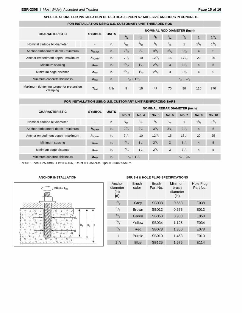
SPECIFICATION
F
ARACTERISTIC
bide bit diameter
edment depth - m
dment depth - m
imum spacing
um edge distance
m concrete thickne
ening torque for pclamping
FO
ARACTERISTIC
bide bit diameter
edment depth - m
dment depth - m
imum spacing
um edge distance
m concrete thickne
5.4mm, 1 lbf = 4.4
HOR INSTALLA
3—ITW RED HEATION INSTRUCT
cepted and Tru
NS FOR INSTALL
FOR INSTALLA
SY
minimum
aximum
e
ess
pretension
OR INSTALLATIO
SY
minimum
aximum
e
ess
45N, 1ft-lbf = 1.3
ATION
AD S7 ADHESIVTIONS (Continu
usted
LATION OF RED
ATION USING U.
YMBOL UNIT
- in.
hef, min in.
hef, max in.
smin in.
cmin in.
hmin in.
Tinst ft lb
ON USING U.S.
YMBOL UNIT
- in.
hef, min in.
hef, max in.
smin in.
cmin in.
hmin in.
356N-m, 1psi = 0
VE ued)
Adi
D HEAD EPCON
S. CUSTOMARY
TS 3/8
7/16
23/8
71/2
15/16
15/16
hef + 1
b 9
CUSTOMARY U
TS No. 3
7/16
23/8
71/2
15/16
15/16
hef + 1
0.006895MPa.
BRUSH
Anchor ameter (in) (d)
Brco
3/8 G1/2 Br5/8 G3/4 Ye7/8 R
1 Pu
11/4 B
N S7 ADHESIVE
Y UNIT THREAD
NOMINAL
1/2 5/8
9/16 3/4
23/4 31/8
10 121/2
11/2 21/2
11/2 21/2
11/4
16 47
UNIT REINFORC
NOMINAL
No. 4 No. 5
5/8 3/4
23/4 31/8
10 121/2
11/2 21/2
11/2 21/2
11/4
H & HOLE PLUG
rush olor
BrusPart N
Grey SB0
rown SB0
reen SB0
ellow SB0
Red SB0
urple SB0
Blue SB1
E ANCHORS IN C
DED ROD
L ROD DIAMETE
3/4
7/8
31/2
2 15
3
3
he
70
CING BARS
REBAR DIAMET
5 No. 6 N
7/8
31/2
2 15
3
3
he
G SPECIFICATI
sh No.
Minimubrush
diamete(in)
038 0.563
012 0.675
058 0.900
034 1.125
078 1.350
010 1.463
25 1.575
Pag
CONCRETE
ER (inch)
7/8 1
1 11/8
31/2 4
171/2 20
31/2 4
31/2 4
ef + 2do
90 110
TER (inch)
No. 7 No. 8
1 11/8
31/2 4
171/2 20
31/2 4
31/2 4
ef + 2do
ONS
um h er
Hole PluPart No
3 E038
5 E012
0 E058
5 E034
0 E078
3 E010
5 E114
ge 15 of 16
11/4
13/8
5
25
5
5
370
No. 10
13/8
5
25
5
5
ug o.
8
2
8
4
8
0
4

ESR-2308 | Most Widely Accepted and Trusted Page 16 of 16
CURE TIMES AND GEL TIMES FOR RED HEAD EPCON S7 ADHESIVE
Concrete Temperature (°F)1,2
Gel Time3 Cure Time4
90 2 minutes 30 minutes
70 4 minutes 30 minutes
50 6 minutes 45 minutes
30 14 minutes 2 hours
14 30 minutes 12 hours
For SI: t° (°F-32) X .555 = °C. 1Adhesive must be installed in concrete temperatures within the noted range or artificially maintained at the noted temperature. 2 For concrete temperatures between 14°F and 30°F, adhesive must be maintained at a minimum of 30°F during installation. 3Gel time is the maximum time from the end of mixing to when the insertion of the anchor into the adhesive shall be completed and is based upon the adhesive and concrete temperatures noted. 4Cure time is the minimum time from the end of gel time to when the anchor maybe torque or loaded. Anchors are to be undisturbed during the cure time.
FIGURE 3—RED HEAD EPCON S7 ADHESIVE INSTALLATION INSTRUCTIONS (Continued)

ICC-ES Evaluation Reports are not to be construed as representing aesthetics or any other attributes not specifically addressed, nor are they to be construed as an endorsement of the subject of the report or a recommendation for its use. There is no warranty by ICC Evaluation Service, LLC, express or implied, as to any finding or other matter in this report, or as to any product covered by the report.
Copyright © 2015 ICC Evaluation Service, LLC. All rights reserved. Page 1 of 1 1000
ICC-ES Evaluation Report ESR-2308 FBC Supplement Reissued May 2015 Revised November 2015
This report is subject to renewal May 2016.
www.icc-es.org | (800) 423-6587 | (562) 699-0543 A Subsidiary of the International Code Council ®
DIVISION: 03 00 00—CONCRETE Section: 03 16 00—Concrete Anchors DIVISION: 05 00 00—METALS Section: 05 05 19—Post-Installed Concrete Anchors REPORT HOLDER: ITW RED HEAD 700 HIGH GROVE BOULEVARD GLENDALE HEIGHTS, ILLINOIS 60139 (800) 848-5611 www.itw-redhead.com [email protected] EVALUATION SUBJECT: ITW RED HEAD EPCON S7 ADHESIVE ANCHORING FOR CRACKED AND UNCRACKED CONCRETE 1.0 REPORT PURPOSE AND SCOPE
Purpose:
The purpose of this evaluation report supplement is to indicate that the Red Head Epcon S7 Adhesive Anchoring System for Cracked and Uncracked Concrete, recognized in ICC-ES master evaluation report ESR-2308, has also been evaluated for compliance with the codes notes below.
Applicable code editions:
2014 and 2010 Florida Building Code—Building
2014 and 2010 Florida Building Code—Residential
2.0 CONCLUSIONS
The Red Head Epcon S7 Adhesive Anchoring System for Cracked and Uncracked Concrete, described in Sections 2.0 through 7.0 of the master evaluation report ESR-2307, complies with the 2014 and 2010 Florida Building Code—Building and the 2014 and 2010 Florida Building Code—Residential, provided the design and installation are in accordance with the International Building Code® (IBC) provisions noted in the master report, as applicable.
Exception: The modifications to ACI 318-11 as shown in 2009 IBC Sections 1908.1.9 and 1908.1.10, and as noted in 2009 IBC Section 1912.1, do not apply to the 2010 Florida Building Code.
Use of the Red Head Epcon S7 Adhesive Anchoring System for Cracked and Uncracked Concrete with stainless steel threaded rod materials has also been found to be in compliance with the High-Velocity Hurricane Zone provisions of the 2014 and 2010 Florida Building Code-Building and the 2014 and 2010 Florida Building Code-Residential.
For products falling under Florida Rule 9N-3, verification that the report holder’s quality-assurance program is audited by a quality-assurance entity approved by the Florida Building Commission for the type of inspections being conducted is the responsibility of an approved validation entity (or the code official when the report holder does not possess an approval by the Commission).
This supplement expires concurrently with the master report, reissued May 2015 and revised November 2015.