more digital circuits - cs61c/sp19/lectures/lec10.pdf · type of circuits • synchronous digital...
TRANSCRIPT

Computer Science 61C Spring 2019 Weaver
More Digital Circuits
1
Computer Science 61C Spring 2019 Weaver
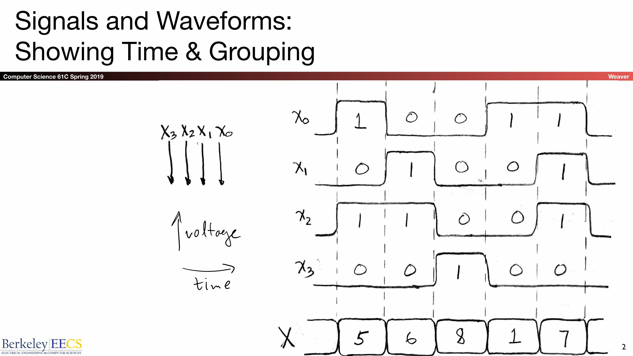
Signals and Waveforms: Showing Time & Grouping
2
Computer Science 61C Spring 2019 Weaver
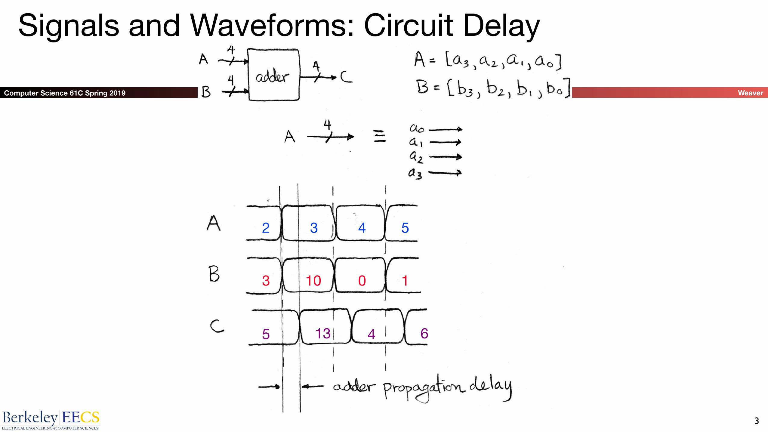
Signals and Waveforms: Circuit Delay
3
2
3
3 4 5
10 0 1
5 13 4 6

Computer Science 61C Spring 2019 Weaver
Sample Debugging Waveform
4

Computer Science 61C Spring 2019 Weaver
Type of Circuits
• Synchronous Digital Systems consist of two basic types of circuits:• Combinational Logic (CL) circuits
– Output is a function of the inputs only, not the history of its execution– E.g., circuits to add A, B (ALUs)• Sequential Logic (SL)• Circuits that “remember” or store information• aka “State Elements”• E.g., memories and registers (Registers)
5

Computer Science 61C Spring 2019 Weaver
Uses for State Elements
• Place to store values for later re-use:• Register files (like x1-x31 in RISC-V)• Memory (caches and main memory)
• Help control flow of information between combinational logic blocks • State elements hold up the movement of information at input to
combinational logic blocks to allow for orderly passage
6

Computer Science 61C Spring 2019 Weaver
Accumulator Example
Want: S=0; for (i=0;i<n;i++) S = S + Xi
Why do we need to control the flow of information?
Assume:• Each X value is applied in succession, one per cycle• After n cycles the sum is present on S
7
SUMXi S
Computer Science 61C Spring 2019 Weaver
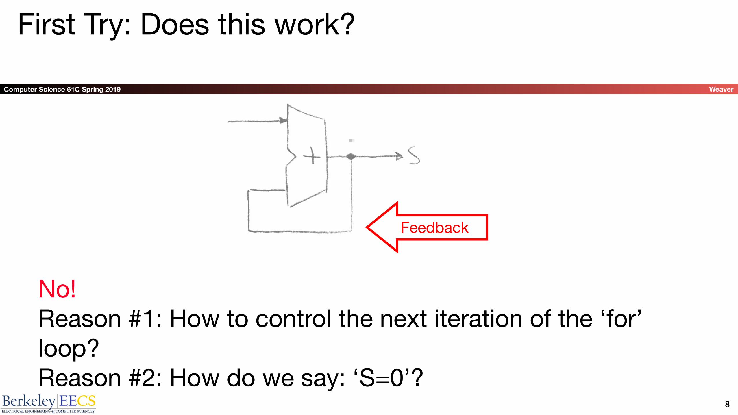
First Try: Does this work?
8
No! Reason #1: How to control the next iteration of the ‘for’ loop?Reason #2: How do we say: ‘S=0’?
Feedback
Computer Science 61C Spring 2019 Weaver
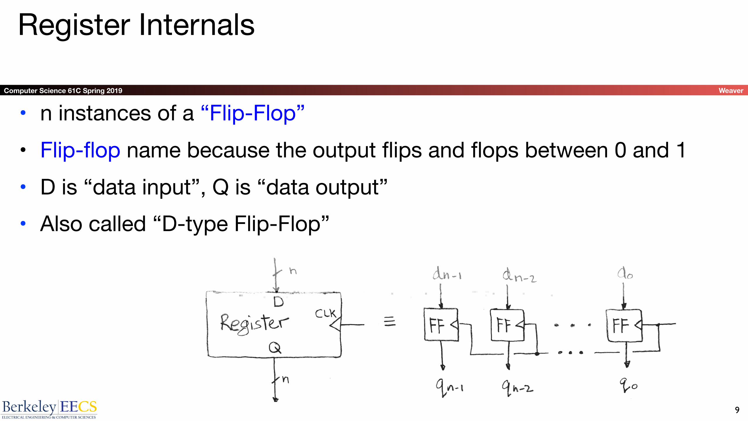
Register Internals
• n instances of a “Flip-Flop”• Flip-flop name because the output flips and flops between 0 and 1 • D is “data input”, Q is “data output”• Also called “D-type Flip-Flop”
9

Computer Science 61C Spring 2019 Weaver
Flip-Flop Operation
• Edge-triggered d-type flip-flop• This one is “positive edge-triggered”
• “On the rising edge of the clock, the input d is sampled and transferred to the output. At all other times, the input d is ignored.”
• Example waveforms:
10

Computer Science 61C Spring 2019 Weaver
Flip-Flop Timing
• Edge-triggered d-type flip-flop• This one is “positive edge-triggered”
• “On the rising edge of the clock, the input d is sampled and transferred to the output. At all other times, the input d is ignored.”
• Example waveforms (more detail):
11

Computer Science 61C Spring 2019 Weaver
Camera Analogy Timing Terms
• Want to take a portrait – timing right before and after taking picture
• Set up time – don’t move since about to take picture (open camera shutter)
• Hold time – need to hold still after shutter opens until camera shutter closes
• Time click to data – time from open shutter until can see image on output (viewscreen)
12
Computer Science 61C Spring 2019 Weaver
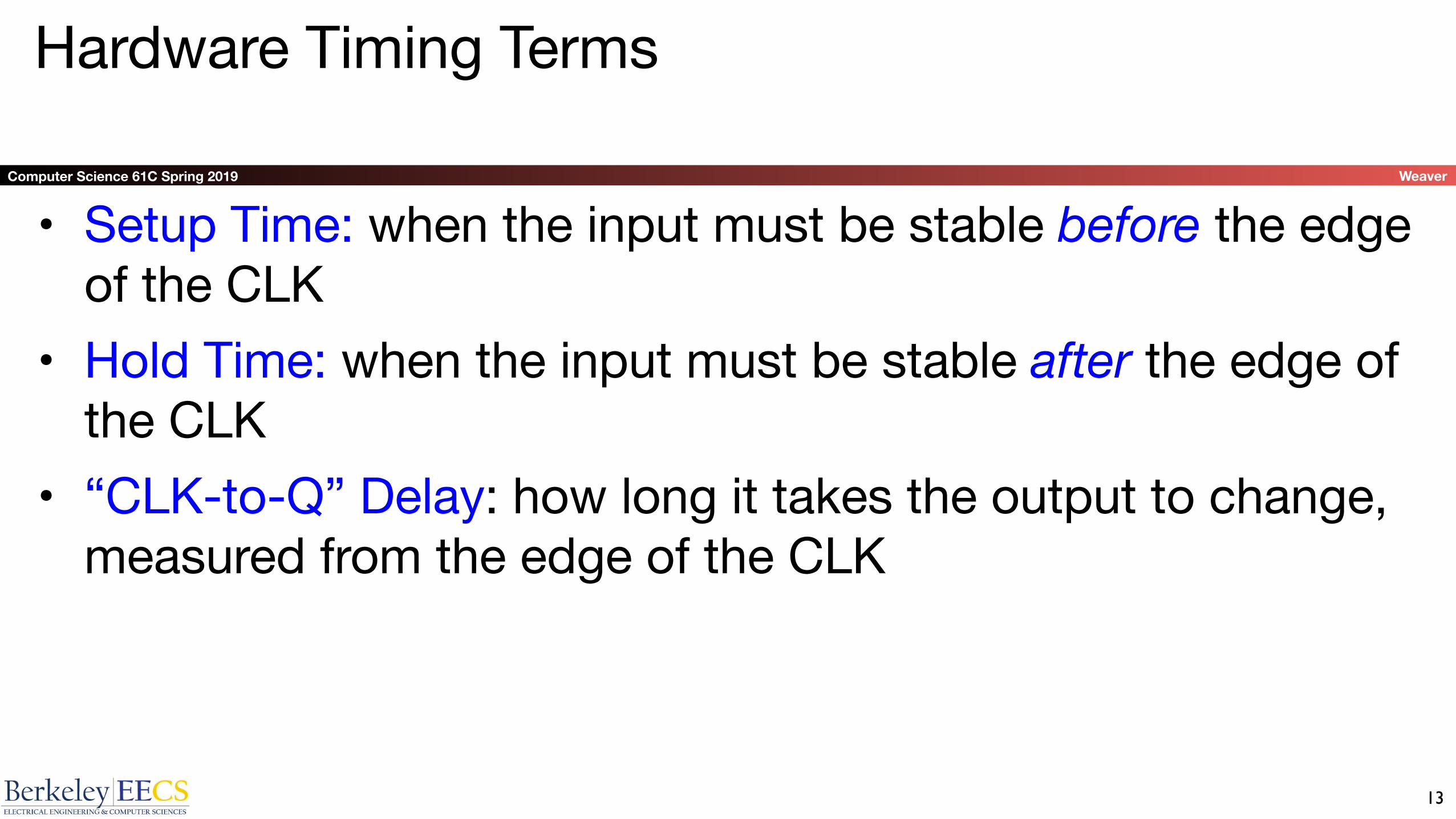
Hardware Timing Terms
• Setup Time: when the input must be stable before the edge of the CLK
• Hold Time: when the input must be stable after the edge of the CLK
• “CLK-to-Q” Delay: how long it takes the output to change, measured from the edge of the CLK
13

Computer Science 61C Spring 2019 Weaver
So How To Build A Flip Flop?Two "Latches". An example...• When clk is high...• D -> Q
• When clk is low...• Q stays with whatever it was
• Chain 2 latches together to create a flip-flop• Setup time:• Need to propagate D to Q on the first latch
• Hold time:• Need to make sure the first latch doesn't change before
the clock fully switches
• Clk->Q time:• Time needed to go through the second latch
14
D-Type Latch
D Q
CLK
D Q
CLK
D Q
CLK
D-Type FF from 2 D-Latches

Computer Science 61C Spring 2019 Weaver
Accumulator Timing 1/2
• Reset input to register is used to force it to all zeros (takes priority over D input).
• Si-1 holds the result of the ith-1 iteration.
• Analyze circuit timing starting at the output of the register.
15

Computer Science 61C Spring 2019 Weaver
Accumulator Timing 2/2
• reset signal shown.
• Also, in practice X might not arrive to the adder at the same time as Si-1
• Si temporarily is wrong, but register always captures correct value.
• In good circuits, instability never happens around rising edge of clk.
16
Computer Science 61C Spring 2019 Weaver
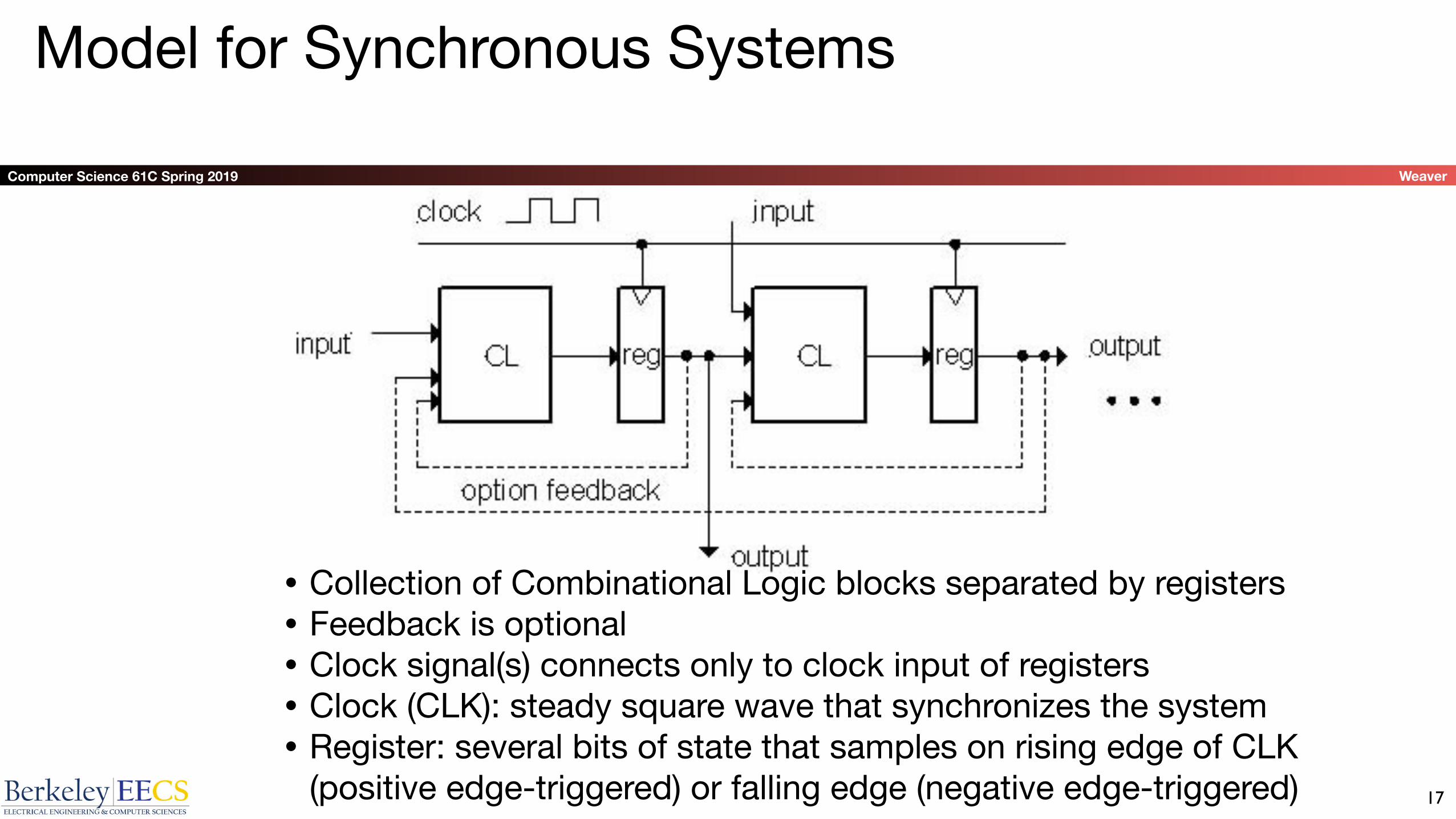
Model for Synchronous Systems
17
• Collection of Combinational Logic blocks separated by registers• Feedback is optional• Clock signal(s) connects only to clock input of registers• Clock (CLK): steady square wave that synchronizes the system• Register: several bits of state that samples on rising edge of CLK
(positive edge-triggered) or falling edge (negative edge-triggered)
Computer Science 61C Spring 2019 Weaver
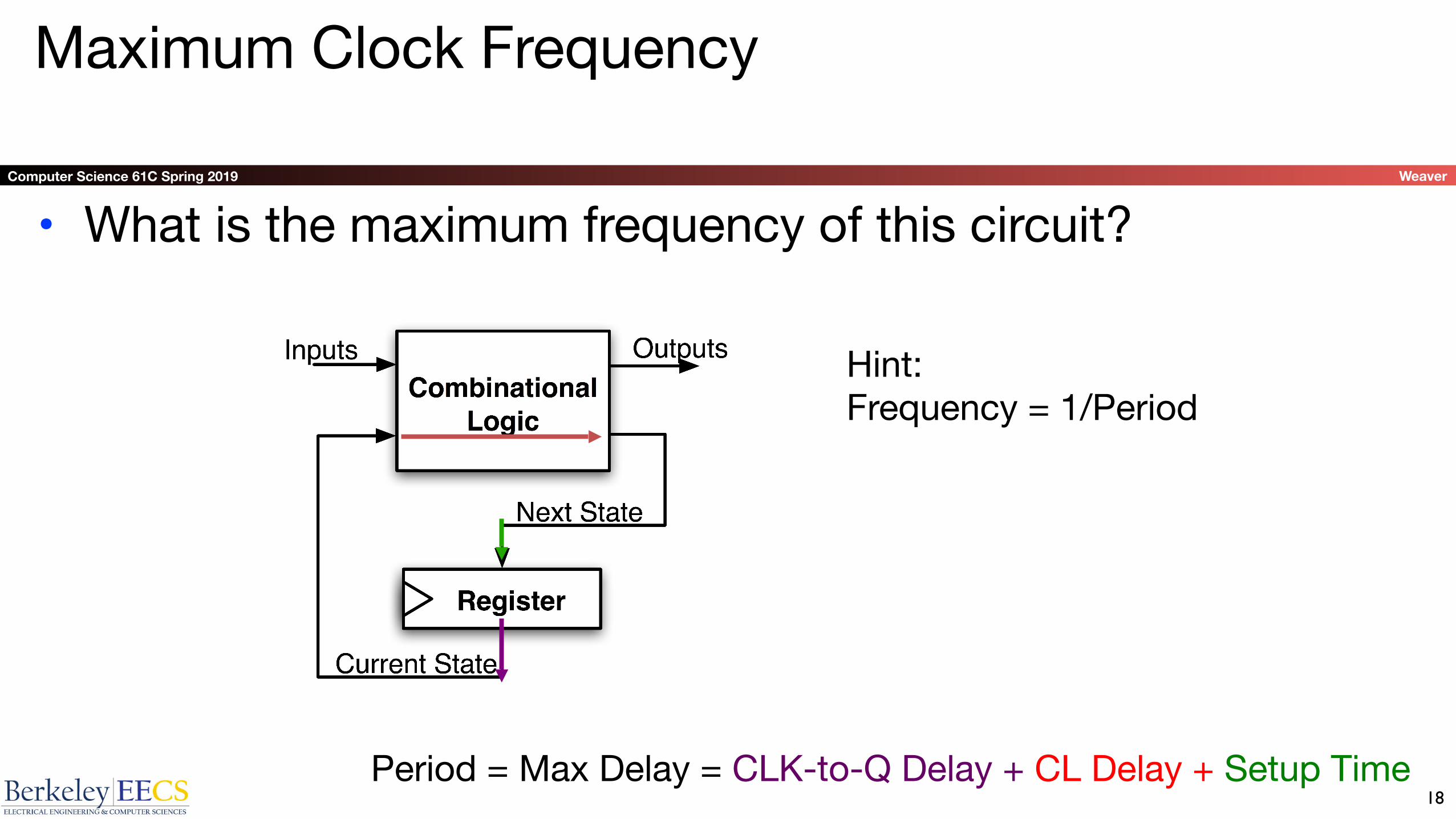
Maximum Clock Frequency
• What is the maximum frequency of this circuit?
18Period = Max Delay = CLK-to-Q Delay + CL Delay + Setup Time
Hint:Frequency = 1/Period

Computer Science 61C Spring 2019 Weaver
Critical Paths
19
Timing…
Note: delay of 1 clock cycle from input to output.Clock period limited by propagation delay of adder/shifter.

Computer Science 61C Spring 2019 Weaver
Pipelining to improve performance
20
Timing…
• Insertion of register allows higher clock frequency• More outputs per second (higher bandwidth)• But each individual result takes longer (greater latency)

Computer Science 61C Spring 2019 Weaver
Recap of Timing Terms
• Clock (CLK) - steady square wave that synchronizes system• Setup Time - when the input must be stable before the rising edge of the CLK• Hold Time - when the input must be stable after the rising edge of the CLK• “CLK-to-Q” Delay - how long it takes the output to change, measured from the
rising edge of the CLK
• Flip-flop - one bit of state that samples every rising edge of the CLK (positive edge-triggered)
• Register - several bits of state that samples on rising edge of CLK or on LOAD (positive edge-triggered)
21

Computer Science 61C Spring 2019 Weaver
Administrivia
• Project PAARRTTTAAYYY!!!• Wednesday, 2nd floor labs, 7-9pm• Project 2 due 3/1
• Exam grades will be released tonight with solutions• Regrades must be submitted by 23:59 on Sunday
• Project 3 released 3/2...
22

Computer Science 61C Spring 2019 Weaver
Clickers/Peer Instruction
What is maximum clock frequency? (assume all unconnected inputs come from some register)• A: 5 GHz • B: 200 MHz• C: 500 MHz• D: 1/7 GHz• E: 1/6 GHz
23
Clock->Q 1nsSetup 1nsHold 1nsAND delay 1ns

Computer Science 61C Spring 2019 Weaver
Problems With Clocking...
• The clock period must be longer than the critical path• Otherwise, you will get the wrong answers• But it can be even longer than that
• Critical path:• clk->q time• Necessary to get the output of the registers• worst case combinational logic delay• Setup time for the next register
• Must meet all of these to be correct
24

Computer Science 61C Spring 2019 Weaver
Hold-Time Violations...
• An alternate problem can occur...• Clk->Q + best case combinational delay < Hold time...
• What happens?• Clk->Q + data propagates...• And now you don't hold the input to the flip flop long enough
• Solution:• Add delay on the best-case path (e.g. two inverters)
25

Computer Science 61C Spring 2019 Weaver
Finite State Machines (FSM) Intro
• A convenient way to conceptualize computation over time•We start at a state and given
an input, we follow some edge to another (or the same) state• The function can be
represented with a “state transition diagram”.•With combinational logic and
registers, any FSM can be implemented in hardware. 26

Computer Science 61C Spring 2019 Weaver
FSM Example: 3 ones…
Draw the FSM:FSM to detect the occurrence of 3 consecutive 1’s in the input.
Assume state transitions are controlled by the clock:On each clock cycle the machine checks the inputs and moves to a new state and produces a new output…
Input/Output
27

Computer Science 61C Spring 2019 Weaver
Hardware Implementation of FSM
+ =
…therefore a register is needed to hold the a representation of which state the machine is in. Use a unique bit pattern for each state.
Combinational logic circuit is used to implement a function that maps from present state and input to next state and output.
28
Computer Science 61C Spring 2019 Weaver
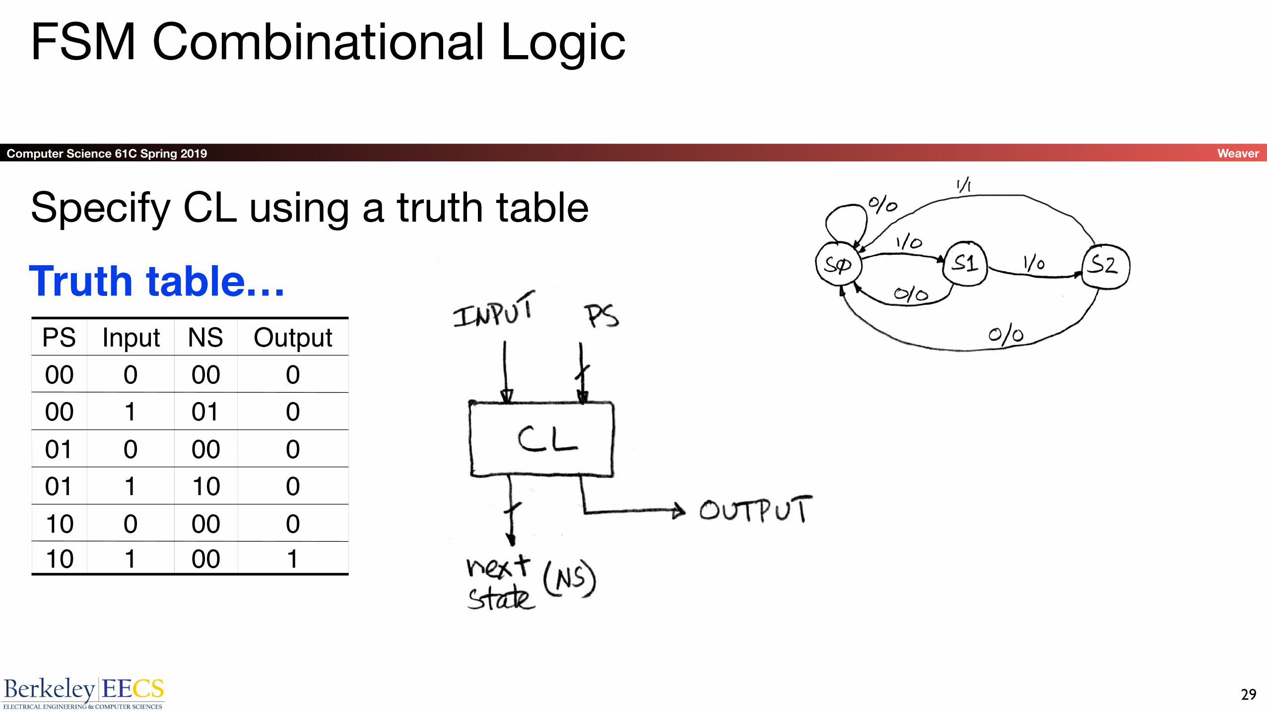
FSM Combinational Logic
100110000010010101000001001100000000
OutputNSInputPS
Truth table…Specify CL using a truth table
29
Computer Science 61C Spring 2019 Weaver
Building Standard Functional Units
• Data multiplexers• Arithmetic and Logic Unit• Adder/Subtractor
30

Computer Science 61C Spring 2019 Weaver
Data Multiplexer (“Mux”) (here 2-to-1, n-bit-wide)
31

Computer Science 61C Spring 2019 Weaver
N instances of 1-bit-wide muxHow many rows in TT?
32
Computer Science 61C Spring 2019 Weaver
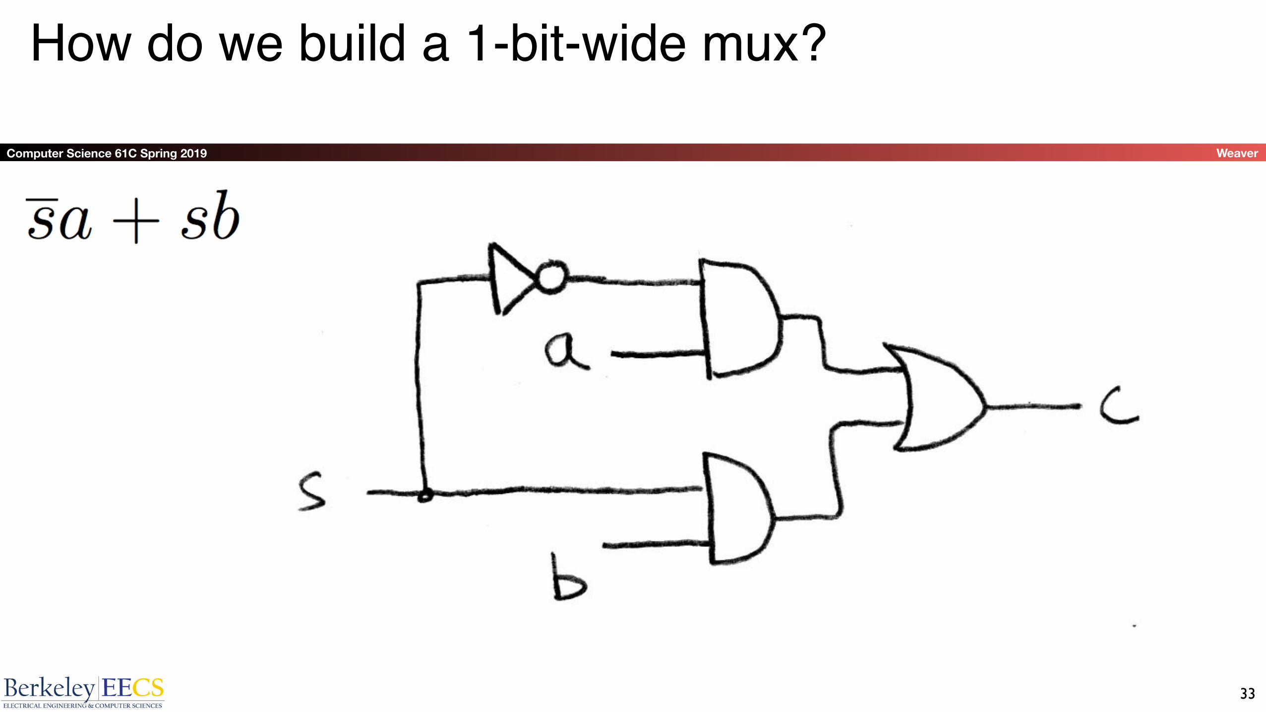
How do we build a 1-bit-wide mux?
33

Computer Science 61C Spring 2019 Weaver
4-to-1 multiplexer?
How many rows in TT?
34
Computer Science 61C Spring 2019 Weaver
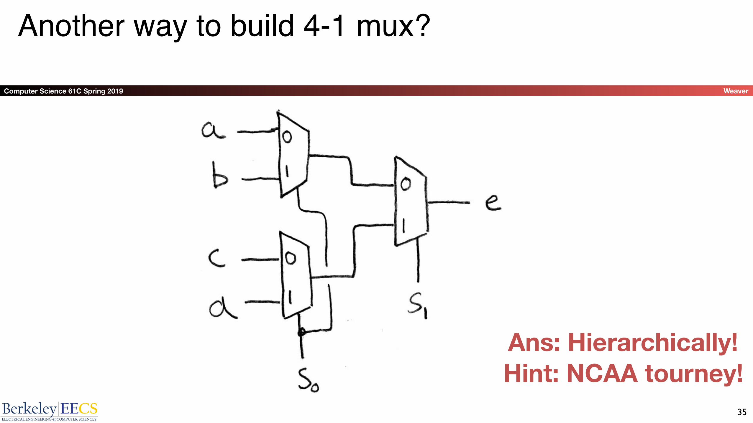
Another way to build 4-1 mux?
Hint: NCAA tourney!Ans: Hierarchically!
35

Computer Science 61C Spring 2019 Weaver
Arithmetic and Logic Unit
• Most processors contain a special logic block called the “Arithmetic and Logic Unit” (ALU)
• We’ll show you an easy one that does ADD, SUB, bitwise AND, bitwise OR
36

Computer Science 61C Spring 2019 Weaver
Our simple ALU
37

Computer Science 61C Spring 2019 Weaver
How to design Adder/Subtractor?
• Truth-table, then determine canonical form, then minimize and implement as we’ve seen before
• Look at breaking the problem down into smaller pieces that we can cascade or hierarchically layer
38

Computer Science 61C Spring 2019 Weaver
Adder/Subtractor – One-bit adder LSB…
39

Computer Science 61C Spring 2019 Weaver
Adder/Subtractor – One-bit adder (1/2)…
40

Computer Science 61C Spring 2019 Weaver
Adder/Subtractor – One-bit adder (2/2)
41
Computer Science 61C Spring 2019 Weaver
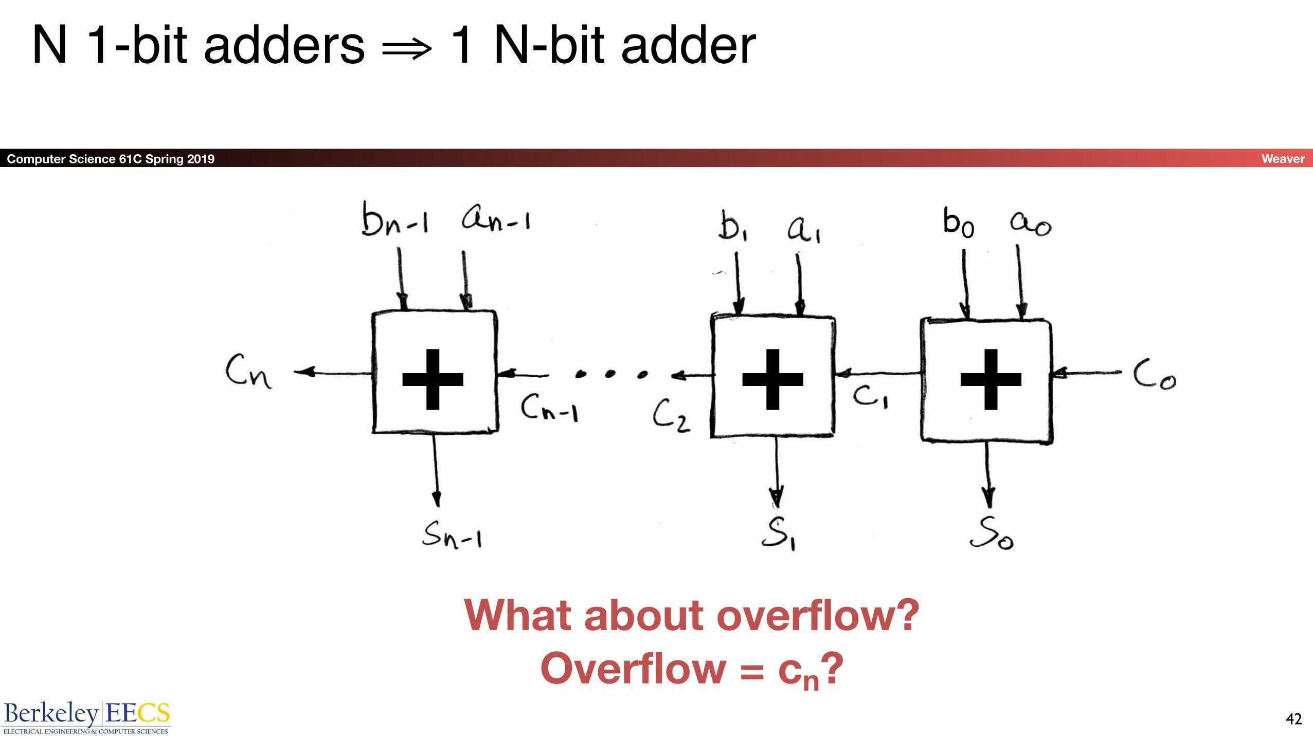
N 1-bit adders ⇒ 1 N-bit adder
What about overflow? Overflow = cn?
+ + +b0
42

Computer Science 61C Spring 2019 Weaver
Extremely Clever Adder/Subtractor:"Invert and add one"
x y XOR(x,y)0 0 00 1 11 0 11 1 0
+ + +
XOR serves as conditional inverter! 43

Computer Science 61C Spring 2019 Weaver
iClicker Question
Convert the truth table to a boolean expression (no need to simplify):
A: F = xy + x(~y)
B: F = xy + (~x)y + (~x)(~y)
C: F = (~x)y + x(~y)
D: F = xy + (~x)y
E: F = (x+y)(~x+~y)
44
x y F(x,y)0 0 00 1 11 0 01 1 1
Computer Science 61C Spring 2019 Weaver
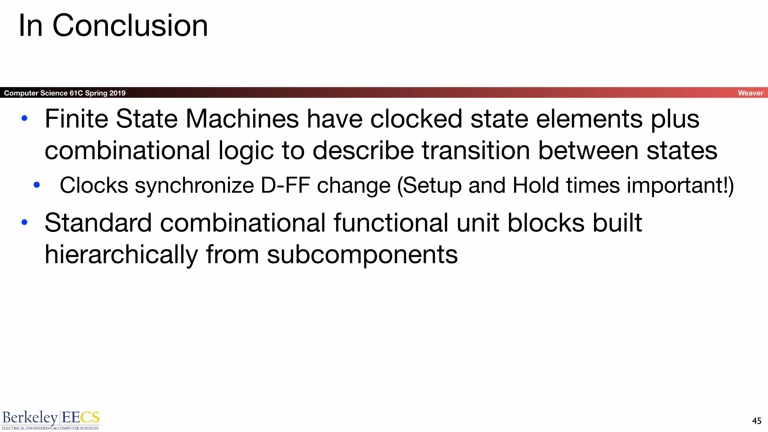
In Conclusion
• Finite State Machines have clocked state elements plus combinational logic to describe transition between states• Clocks synchronize D-FF change (Setup and Hold times important!)• Standard combinational functional unit blocks built
hierarchically from subcomponents
45
Computer Science 61C Spring 2019 Weaver
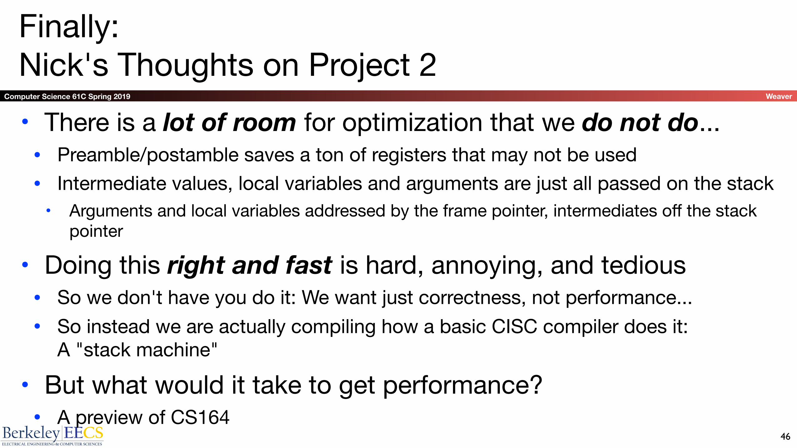
Finally:Nick's Thoughts on Project 2• There is a lot of room for optimization that we do not do...• Preamble/postamble saves a ton of registers that may not be used• Intermediate values, local variables and arguments are just all passed on the stack• Arguments and local variables addressed by the frame pointer, intermediates off the stack
pointer
• Doing this right and fast is hard, annoying, and tedious• So we don't have you do it: We want just correctness, not performance...• So instead we are actually compiling how a basic CISC compiler does it:
A "stack machine"
• But what would it take to get performance?• A preview of CS164
46

Computer Science 61C Spring 2019 Weaver
The Problem:Register Allocation• One Big RISC idea:• Let us make the compiler writer's job much more annoying in return for
simpler hardware with better performance
• Every value in the function has a "Lifespan"• From when it is first needed (and initialized) to when it is no longer needed• If the lifespan doesn't cross function calls:• Can use temporary registers• If the lifespan does cross function calls:• Must either use saved registers or allocate the data on the stack
47
Computer Science 61C Spring 2019 Weaver
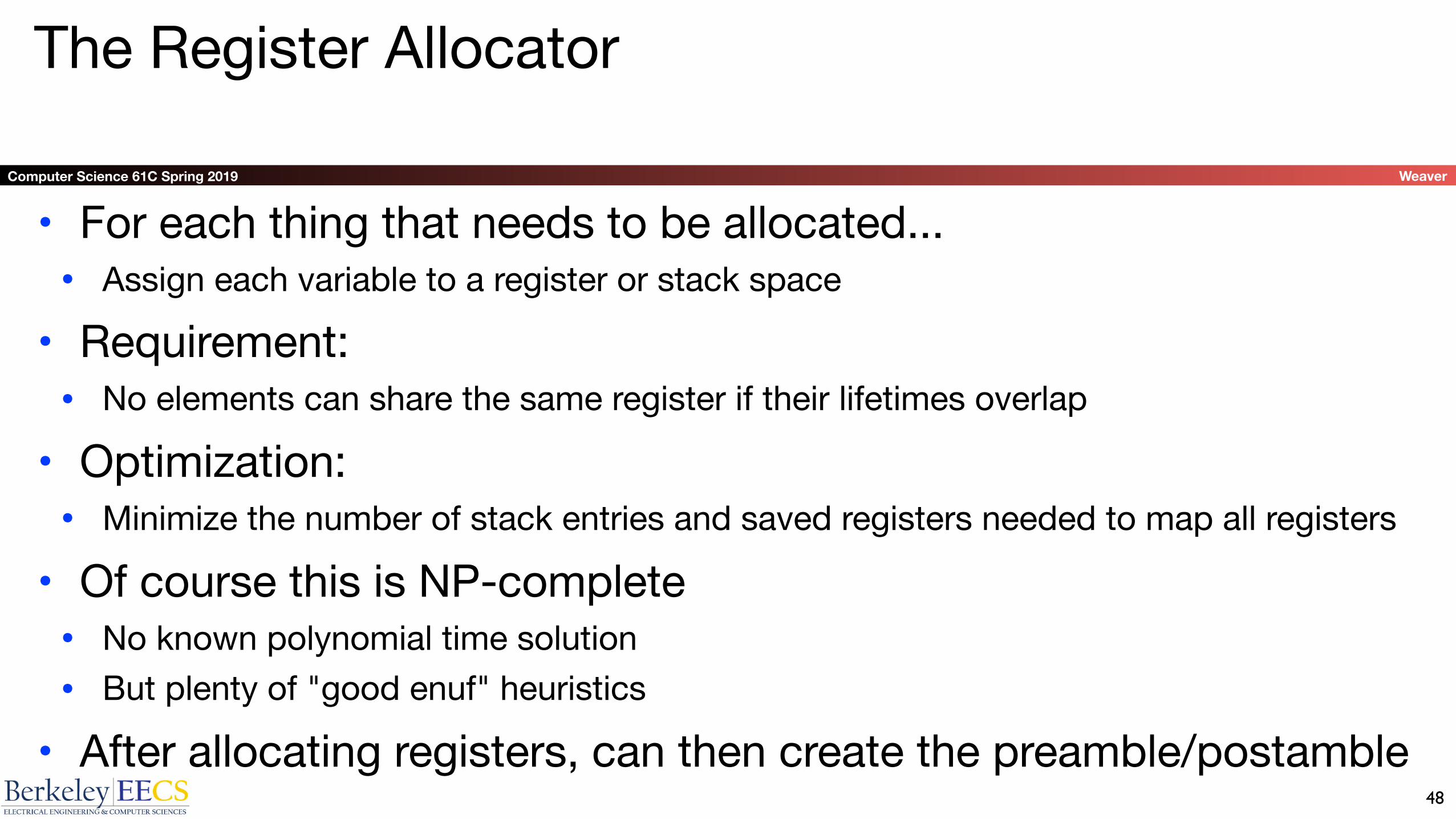
The Register Allocator
• For each thing that needs to be allocated...• Assign each variable to a register or stack space
• Requirement:• No elements can share the same register if their lifetimes overlap
• Optimization:• Minimize the number of stack entries and saved registers needed to map all registers
• Of course this is NP-complete• No known polynomial time solution• But plenty of "good enuf" heuristics
• After allocating registers, can then create the preamble/postamble 48