moog animatics class 6 ethernet/ip guide
TRANSCRIPT

EtherNet/IP Guide
Class 6 SmartMotorTechnology

Copyright Notice©2015–2019, Moog Inc., Animatics.
Moog Animatics Class 6 SmartMotor™ EtherNet/IP Guide, Rev. C, SC80100010-001.
This manual, as well as the software described in it, is furnished under license and may be used or copied only in accordance with the terms of such license. The content of this manual is furnished for informational use only, is subject to change without notice and should not be construed as a commitment by Moog Inc., Animatics. Moog Inc., Animatics assumes no responsibility or liability for any errors or inaccuracies that may appear herein.
Except as permitted by such license, no part of this publication may be reproduced, stored in a retrieval system or transmitted, in any form or by any means, electronic, mechanical, recording, or otherwise, without the prior written permission of Moog Inc., Animatics.
The programs and code samples in this manual are provided for example purposes only. It is the user's responsibility to decide if a particular code sample or program applies to the application being developed and to adjust the values to fit that application.
Moog Animatics and the Moog Animatics logo, SmartMotor and the SmartMotor logo, Combitronic and the Combitronic logo are all trademarks of Moog Inc., Animatics. CIP, DeviceNet and EtherNet/IP are trademarks of ODVA, Inc. Other trademarks are the property of their respective owners.
Please let us know if you find any errors or omissions in this manual so that we can improve it for future readers. Such notifications should contain the words "EtherNet/IP Guide" in the subject line and be sent by e-mail to: [email protected]. Thank you in advance for your contribution.
Contact Us:
Americas - WestMoog Animatics2581 Leghorn StreetMountain View, CA 94043USA
Americas - EastMoog Animatics750 West Sproul RoadSpringfield, PA 19064USA
Tel: 1 650-960-4215 Tel: 1 610-328-4000 x3999Fax: 1 610-605-6216
Support: 1 (888) 356-0357
Website: www.animatics.com
Email: [email protected]

Table of ContentsIntroduction 8
Purpose 9
Combitronic Technology 9
Abbreviations and Definitions 10
Safety Information 12
Safety Symbols 12
Other Safety Considerations 12
Motor Sizing 12
Environmental Considerations 12
Machine Safety 13
Documentation and Training 14
Additional Equipment and Considerations 14
Safety Information Resources 14
Additional Documents 15
Related Guides 15
Other Documents 15
Additional Resources 16
ODVA Resources 16
EtherNet/IP Overview 17
EtherNet/IP Introduction 18
The OSI Model 18
EtherNet/IP Adaptation of CIP 19
Objects 21
Objects 21
Classes, Instances and Attributes 22
Messaging 23
Explicit (Non-cyclic) Messages 23
Implicit (Cyclic) Messages 23
Explicit/Implicit Messaging Example 23
Connections, Wiring and Status LEDs 24
Connectors and Pinouts 25
M-Style Motor Connectors and Pinouts 25
Moog Animatics Industrial Ethernet Cables 26
M-style to M-style Ethernet Cable 26
Moog Animatics Class 6 EtherNet/IP Guide, Rev. C
Page 3 of 165
M-style to RJ45 Ethernet Cable 26
EtherNet/IP Custom Cable 26
Cable Diagram 27
EtherNet/IP Cable Diagram 27
Status LEDs 28
EtherNet/IP on Class 6 SmartMotors 29
EtherNet/IP Implementation 30
EtherNet/IP Identity 30
EtherNet/IP Software Version Numbers 30
Device Profile 30
SmartMotor Device Profile Overview 31
CIP Objects for EtherNet/IP Devices 31
Application Objects for Position Controller Devices 32
Additional Objects 32
EDS File 34
EtherNet/IP User Program Commands 35
Network Settings and Status Commands 36
Combitronic Addressing over Ethernet (UDP) 41
Program Example 41
Status and Diagnostic Codes 42
Status/Error Codes 42
Diagnostic Codes 42
Position Controller Device (0x10) 44
Position Controller Device Application Objects 45
Position Controller Device Object Model 45
Position Controller Implicit I/O Messages 46
General Command and Response Message Types 46
Polled I/O: Consumed General Message Format 47
Polled I/O: Produced General Message Format 48
General Command / Response Message Types 48
Standard Command Types 49
Extended Profile Move Command Types (32-byte message format only) 49
Extended Attribute to Get (32-byte message format only) 50
Attribute GET/SET Command Types 0x1A and 0x1B 51
Polled I/O: Consumed Message Format 51
Polled I/O: Produced Message Format 51
Moog Animatics Class 6 EtherNet/IP Guide, Rev. C
Page 4 of 165

Attribute Message Types 51
Error Response Message Type (0x14) 52
Polled I/O: Produced Error Response Message Format 52
Error Codes for Position Controller Device 52
Semantics for Command and Response Messages 53
Command Message Semantics 53
Response Message Semantics 54
Position Controller I/O Handshaking 56
Client Data Loading Procedure 56
Client Profile Move Procedure 57
Profile Moves 57
Torque Command 58
Control Mode Change - Change Dynamic 58
Position Controller Implicit I/O Message Examples 59
SmartMotor Notes 59
Set Acceleration 59
Set Velocity, Leave Drive ON 60
Set Target Position, Perform Move 60
Disable Hardware Limits (Object 0x25, Attribute 49) 60
Extended Position Move (32-byte frame) 61
Object Reference 62
Required Objects 64
Identity Object (0x01) 65
Class Attributes 65
Identity Attributes 65
Services 68
Message Router Object (0x02) 69
Class Attributes 69
Instance Attributes 69
Services 69
Assembly Object (0x04) 70
Class Attributes 70
Instance Attributes 70
Services 70
Connection Manager Object (0x06) 71
Class Attributes 71
Instance Attributes 71
Moog Animatics Class 6 EtherNet/IP Guide, Rev. C
Page 5 of 165

Services 71
TCP/IP Interface Object (0xF5) 72
Class Attributes 72
Instance Attributes 72
Services 78
Ethernet Link Object (0xF6) 79
Class Attributes 79
Instance Attributes 79
Services 84
Application Objects 85
Position Controller Supervisor (0x24) 86
Class Attributes 86
Object Instance 1 Attributes 87
Services 87
Position Controller (0x25) 88
Class Attributes 88
Instance Attributes 88
Services 92
Error Responses 92
Additional Objects 93
Device Level Ring (DLR) Object (0x47) 94
Class Attributes 94
Instance Attributes 94
Services 95
QoS Object (0x48) 96
Class Attributes 96
Instance Attributes 96
Services 97
SmartMotor I/O Object (0x71) 98
Attribute Table (Instance 0) 98
Attribute Table (One instance per I/O pin) 98
SmartMotor User Variable Object (0x72) 99
Class Attribute (Instance 0) 99
Instance Attributes (Instance 1-7) 100
Semantics 100
Error Responses 100
Instance Descriptions 101
Examples 102
Moog Animatics Class 6 EtherNet/IP Guide, Rev. C
Page 6 of 165

AOI Descriptions - Allen Bradley PLC 106
SM6_Attribute_Ext_Clear - Clear Attribute to Get (Extended Command) 108
SM6_Attribute_Ext_Get - Load Attribute to Get ID & Wait (Extended Command) 109
SM6_Attribute_Ext_Load - Load Attribute to Get ID (Extended Command) 110
SM6_Attribute_Ext_Value - Return Attribute data (Extended Command) 112
SM6_Clear_Flags - Reset System State Flag 114
SM6_Disable - Disable Drive 115
SM6_Drive - Drive Data Exchange 116
SM6_Enable - Enable Drive 118
SM6_Get_Attribute - Get Drive Attribute 119
SM6_Move_Position_Ext - Position Move(Extended Command) 120
SM6_Move_Velocity_Ext - Velocity Move(Extended Command) 122
SM6_Move_Torque - Apply Torque 124
SM6_Set_Acceleration - Set Drive Acceleration 125
SM6_Set_Attribute - Set Drive Attribute 126
SM6_Set_Deceleration - Set Drive Deceleration 127
SM6_Set_Mode - Set Drive Mode 128
SM6_Set_Position - Set Drive Position 129
SM6_Set_Variable_u - Set Drive Variable "u" 130
SM6_Set_Velocity - Set Drive Target Velocity 131
SM6_Stop_Hard - Perform a Hard Stop 132
SM6_Stop_Smooth - Perform a Smooth Stop 133
Adding AOI Support - Allen Bradley PLC 134
Extracting the SmartMotor Support files 135
Adding a SmartMotor Module 136
Importing the UDTs 143
Importing the AOIs 147
SmartMotor AOI Example 151
Troubleshooting 161
Reference Documents 163
ODVA Specifications 163
ODVA Libraries 163
Moog Animatics Class 6 EtherNet/IP Guide, Rev. C
Page 7 of 165

Introduction
IntroductionThis chapter provides information on the purpose and scope of this manual. It also provides information on safety notation, related documents and additional resources.
Purpose 9
Combitronic Technology 9
Abbreviations and Definitions 10
Safety Information 12
Safety Symbols 12
Other Safety Considerations 12
Motor Sizing 12
Environmental Considerations 12
Machine Safety 13
Documentation and Training 14
Additional Equipment and Considerations 14
Safety Information Resources 14
Additional Documents 15
Related Guides 15
Other Documents 15
Additional Resources 16
ODVA Resources 16
Moog Animatics Class 6 EtherNet/IP Guide, Rev. C
Page 8 of 165

Purpose
PurposeThis manual explains the Moog Animatics Class 6 SmartMotor™ support for the EtherNet/IP™ protocol. It describes the major concepts that must be understood to integrate a SmartMotor slave with a PLC or other EtherNet/IP master. However, it does not cover all the low-level details of the EtherNet/IP protocol.
NOTE: The feature set described in this manual requires a specific motor firmware version. Please consult Moog Animatics for the proper software version.
This manual is intended for programmers or system developers who have read and understand THE CIP NETWORKS LIBRARY Volume 1 - Common Industrial Protocol (CIP™) and THE CIP NETWORKS LIBRARY Volume 2 - EtherNet/IP Adaptation of CIP, which are published and maintained by ODVA.org (http://www.odva.org). Therefore, this manual is not a tutorial on those specifications or the EtherNet/IP protocol. Instead, it should be used to understand the specific implementation details for the Moog Animatics SmartMotor. For a general overview of EtherNet/IP, see EtherNet/IP Overview on page 17.
The reference chapters of this manual include details about the specific commands available in the SmartMotor through the EtherNet/IP protocol. The commands include those required by the specifications and those added by Moog Animatics.
Combitronic TechnologyThe most unique feature of the SmartMotor is its ability to communicate with other SmartMotors and share resources using Moog Animatics’ Combitronic™ technology. On the Class 6 SmartMotor, Combitronic is a protocol that operates over Ethernet and coexists with the EtherNet/IP protocol. It requires no single dedicated master to operate. Each SmartMotor connected to the same network communicates on an equal footing, sharing all information, and therefore, sharing all processing resources.
For details on Combitronic addressing over Ethernet, see Combitronic Addressing over Ethernet (UDP) on page 41. For more information on Combitronic communications, see the SmartMotor Developer's Guide.
Moog Animatics Class 6 EtherNet/IP Guide, Rev. C
Page 9 of 165

Abbreviations and Definitions
Abbreviations and DefinitionsThe following table provides a list of abbreviations and definitions of terms that may be used in this manual or related documents.
Abbreviation/Term Description
API Actual Packet Interval
ASCII American Standard Code for Information Interchange
AT Acceleration Target
BOI Buss-Off Interrupt
Client A device that sends a request to, and expects a response from, a server.
Consumer Network device that reads messages from a producer device.
CoS Change of State I/O trigger
DC Direct Current
DLR Device Level Ring. A ring topology that allows the Ethernet devices to keep communicating if there is a break in the ring.
DT Deceleration Target
EDS Electronic Data Sheet. A text file that contains configuration information for the device.
EPR Expected Packet Rate
EtherNet/IP Ethernet Industrial Protocol
Explicit mes-saging
(Non-cyclic) Not time-sensitive, typically used for network and device configuration, and setup of cyclic connections.
FOC Field Oriented Current
FTP File Transfer Protocol
IE Industrial Ethernet
Implicit mes-saging
(Cyclic) Timely, repetitive transfer of data, typically used for I/O control (e.g., PID loop closure).
IN Input
LAN Local Area Network
MACID Media Access Control Identifier
NASM Network Access State Machine
ODVA Open DeviceNet Vendors Association, Inc, which is the standards organ-ization that maintains the specifications for the CIP industrial network pro-tocols.
OUT Output
PDU Protocol Data Unit
PLC Programmable Logic Controller
Moog Animatics Class 6 EtherNet/IP Guide, Rev. C
Page 10 of 165

Abbreviations and Definitions
Abbreviation/Term Description
Producer A device that puts messages on the network for "consumer" devices (other network devices that will read the messages).
PU Position Units
PV Profile Velocity (mode)
PT Position Target
RTE Real-Time Ethernet
Rx Receive
Server A device that receives requests from clients and sends responses to them.
Slave device Device consuming data transfers from a Network Master. A PLC (Pro-grammable Logic Controller) is a good example of a Master.
SMI SmartMotor Interface (software)
STD State Transition Diagram
TCP Transmission Control Protocol
TQ Torque (mode)
Tx Transmit
UDP User Datagram Protocol
UCMM Unconnected Message Manager
VU Velocity Units
VT Velocity Target
Moog Animatics Class 6 EtherNet/IP Guide, Rev. C
Page 11 of 165

Safety Information
Safety InformationThis section describes the safety symbols and other safety information.
Safety SymbolsThe manual may use one or more of the following safety symbols:
WARNING: This symbol indicates a potentially nonlethal mechanical hazard, where failure to follow the instructions could result in serious injury to the operator or major damage to the equipment.
CAUTION: This symbol indicates a potentially minor hazard, where failure to follow the instructions could result in slight injury to the operator or minor damage to the equipment.
NOTE: Notes are used to emphasize non-safety concepts or related information.
Other Safety ConsiderationsThe Moog Animatics SmartMotors are supplied as components that are intended for use in an automated machine or system. As such, it is beyond the scope of this manual to attempt to cover all the safety standards and considerations that are part of the overall machine/system design and manufacturing safety. Therefore, the following information is intended to be used only as a general guideline for the machine/system designer.
It is the responsibility of the machine/system designer to perform a thorough "Risk Assessment" and to ensure that the machine/system and its safeguards comply with the safety standards specified by the governing authority (for example, ISO, OSHA, UL, etc.) for the locale where the machine is being installed and operated. For more details, see Machine Safety on page 13.
Motor Sizing
It is the responsibility of the machine/system designer to select SmartMotors that are properly sized for the specific application. Undersized motors may: perform poorly, cause excessive downtime or cause unsafe operating conditions by not being able to handle the loads placed on them. The System Best Practices document, which is available on the Moog Animatics website, contains information and equations that can be used for selecting the appropriate motor for the application.
Replacement motors must have the same specifications and firmware version used in the approved and validated system. Specification changes or firmware upgrades require the approval of the system designer and may require another Risk Assessment.
Environmental Considerations
It is the responsibility of the machine/system designer to evaluate the intended operating environment for dust, high-humidity or presence of water (for example, a food-processing environment that requires water or steam wash down of equipment), corrosives or chemicals that may come in contact with the machine, etc. Moog Animatics manufactures specialized
Moog Animatics Class 6 EtherNet/IP Guide, Rev. C
Page 12 of 165

Machine Safety
IP-rated motors for operating in extreme conditions. For details, see the Moog Animatics Product Catalog, which is available on the Moog Animatics website.
Machine Safety
In order to protect personnel from any safety hazards in the machine or system, the machine/system builder must perform a "Risk Assessment", which is often based on the ISO 13849 standard. The design/implementation of barriers, emergency stop (E-stop) mechanisms and other safeguards will be driven by the Risk Assessment and the safety standards specified by the governing authority (for example, ISO, OSHA, UL, etc.) for the locale where the machine is being installed and operated. The methodology and details of such an assessment are beyond the scope of this manual. However, there are various sources of Risk Assessment information available in print and on the internet.
NOTE: The following list is an example of items that would be evaluated when performing the Risk Assessment. Additional items may be required. The safeguards must ensure the safety of all personnel who may come in contact with or be in the vicinity of the machine.
In general, the machine/system safeguards must:
l Provide a barrier to prevent unauthorized entry or access to the machine or system. The barrier must be designed so that personnel cannot reach into any identified danger zones.
l Position the control panel so that it is outside the barrier area but located for an unrestricted view of the moving mechanism. The control panel must include an E-stop mechanism. Buttons that start the machine must be protected from accidental activation.
l Provide E-stop mechanisms located at the control panel and at other points around the perimeter of the barrier that will stop all machine movement when tripped.
l Provide appropriate sensors and interlocks on gates or other points of entry into the protected zone that will stop all machine movement when tripped.
l Ensure that if a portable control/programming device is supplied (for example, a hand-held operator/programmer pendant), the device is equipped with an E-stop mechanism.
NOTE: A portable operation/programming device requires many additional system design considerations and safeguards beyond those listed in this section. For details, see the safety standards specified by the governing authority (for example, ISO, OSHA, UL, etc.) for the locale where the machine is being installed and operated.
l Prevent contact with moving mechanisms (for example, arms, gears, belts, pulleys, tooling, etc.).
l Prevent contact with a part that is thrown from the machine tooling or other part-handling equipment.
l Prevent contact with any electrical, hydraulic, pneumatic, thermal, chemical or other hazards that may be present at the machine.
l Prevent unauthorized access to wiring and power-supply cabinets, electrical boxes, etc.
Moog Animatics Class 6 EtherNet/IP Guide, Rev. C
Page 13 of 165
Documentation and Training
l Provide a proper control system, program logic and error checking to ensure the safety of all personnel and equipment (for example, to prevent a run-away condition). The control system must be designed so that it does not automatically restart the machine/system after a power failure.
l Prevent unauthorized access or changes to the control system or software.
Documentation and Training
It is the responsibility of the machine/system designer to provide documentation on safety, operation, maintenance and programming, along with training for all machine operators, maintenance technicians, programmers, and other personnel who may have access to the machine. This documentation must include proper lockout/tagout procedures for maintenance and programming operations.
It is the responsibility of the operating company to ensure that:
l All operators, maintenance technicians, programmers and other personnel are tested and qualified before acquiring access to the machine or system.
l The above personnel perform their assigned functions in a responsible and safe manner to comply with the procedures in the supplied documentation and the company safety practices.
l The equipment is maintained as described in the documentation and training supplied by the machine/system designer.
Additional Equipment and Considerations
The Risk Assessment and the operating company's standard safety policies will dictate the need for additional equipment. In general, it is the responsibility of the operating company to ensure that:
l Unauthorized access to the machine is prevented at all times.
l The personnel are supplied with the proper equipment for the environment and their job functions, which may include: safety glasses, hearing protection, safety footwear, smocks or aprons, gloves, hard hats and other protective gear.
l The work area is equipped with proper safety equipment such as first aid equipment, fire suppression equipment, emergency eye wash and full-body wash stations, etc.
l There are no modifications made to the machine or system without proper engineering evaluation for design, safety, reliability, etc., and a Risk Assessment.
Safety Information ResourcesAdditional SmartMotor safety information can be found on the Moog Animatics website; open the file "109_Controls, Warnings and Cautions.pdf" located at:
http://www.animatics.com/support/moog-animatics-catalog.html
OSHA standards information can be found at:
https://www.osha.gov/law-regs.html
ANSI-RIA robotic safety information can be found at:
http://www.robotics.org/robotic-content.cfm/Robotics/Safety-Compliance/id/23
Moog Animatics Class 6 EtherNet/IP Guide, Rev. C
Page 14 of 165
Additional Documents
UL standards information can be found at:
http://ulstandards.ul.com/standards-catalog/
ISO standards information can be found at:
http://www.iso.org/iso/home/standards.htm
EU standards information can be found at:
http://ec.europa.eu/growth/single-market/european-standards/harmonised-standards/index_en.htm
Additional DocumentsThe Moog Animatics website contains additional documents that are related to the information in this manual. Please refer to the following list.
Related Guides l Class 6 SmartMotor™ Installation & Startup Guide
http://www.animatics.com/cl-6-install-startup-guide
l SmartMotor™ Developer's Guide
http://www.animatics.com/smartmotor-developers-guide
l SmartMotor™ System Best Practices
http://www.animatics.com/system-best-practices-application-note
Other Documents l SmartMotor™ Product Certificate of Conformance
http://www.animatics.com/download/Declaration of Conformity.pdf
l SmartMotor™ UL Certification
http://www.animatics.com/download/MA_UL_online_listing.pdf
l SmartMotor Developer's Worksheet (interactive tools to assist developer: Scale Factor Calculator, Status Words, CAN Port Status, Serial Port Status, RMODE Decoder and Syntax Error Codes)
http://www.animatics.com/tools
l Moog Animatics Product Catalog, which is available on the Moog Animatics website
http://www.animatics.com/support/moog-animatics-catalog.html
Moog Animatics Class 6 EtherNet/IP Guide, Rev. C
Page 15 of 165

Additional Resources
Additional ResourcesThe Moog Animatics website contains useful resources such as product information, documentation, product support and more. Please refer to the following addresses:
l General company information:
http://www.animatics.com
l Product information:
http://www.animatics.com/products.html
l Product support (Downloads, How To videos, Forums, Knowledge Base, and FAQs):
http://www.animatics.com/support.html
l Sales and distributor information:
http://www.animatics.com/sales-offices.html
l Application ideas (including videos and sample programs):
http://www.animatics.com/applications.html
ODVA ResourcesEtherNet/IP is a common standard maintained by ODVA.org:
l ODVA.org website:
http://www.odva.org/
l An EtherNet/IP Quick Start for Vendors Handbook is available at:
http://www.odva.org/Portals/0/Library/Publications_Numbered/PUB00213R0_EtherNetIP_Developers_Guide.pdf
Moog Animatics Class 6 EtherNet/IP Guide, Rev. C
Page 16 of 165

EtherNet/IP Overview
EtherNet/IP OverviewThis chapter provides an overview of EtherNet/IP features. These sections briefly summarize the technical information provided on the ODVA.org website. To view the fully detailed information or to obtain the specifications, see the ODVA.org website at: http://www.odva.org.
EtherNet/IP Introduction 18
The OSI Model 18
EtherNet/IP Adaptation of CIP 19
Objects 21
Objects 21
Classes, Instances and Attributes 22
Messaging 23
Explicit (Non-cyclic) Messages 23
Implicit (Cyclic) Messages 23
Explicit/Implicit Messaging Example 23
Moog Animatics Class 6 EtherNet/IP Guide, Rev. C
Page 17 of 165

EtherNet/IP Introduction
EtherNet/IP IntroductionEthernet/Industrial Protocol (EtherNet/IP) is a fieldbus communications protocol that was initially developed in the 1990s. It is now a CIP-based technology that is managed by the Open DeviceNet Vendors Association (ODVA), which is a standards organization that manages all CIP network technologies.
EtherNet/IP and DeviceNet are two CIP network technologies that are supported by Moog Animatics (see OSI Model for EtherNet/IP and DeviceNet on page 18). These networks share the same CIP layers and use objects to describe the network devices (this collection of objects specific to a device is the device profile). Because of this, they are able to communicate with each other. For example, a device on an EtherNet/IP network can communicate with one on a DeviceNet network. For more information on CIP objects, see Objects on page 21.
The Class 6 EtherNet/IP SmartMotor is designed to operate as a device on an EtherNet/IP network. This allows the system designer to take advantage of SmartMotor technology through its device profile (for example, start a user program stored in the SmartMotor). For details on the SmartMotor device profile using the Position Controller device, see SmartMotor Device Profile Overview on page 31.
The full specification for EtherNet/IP is available from the ODVA.org website. For details, see THE CIP NETWORKS LIBRARY Volume 1 - Common Industrial Protocol (CIP™) and THE CIP NETWORKS LIBRARY Volume 2 - EtherNet/IP Adaptation of CIP.
The OSI ModelThe OSI model describes the architecture for the CIP-based industrial network protocols. Moog Animatics supports EtherNet/IP and DeviceNet using the Position Controller Supervisor and Position Controller profiles. The other profiles shown are not currently supported.
EtherNet/IPTM DeviceNetTM
Physical
Data Link
Network
Transport
Session
Presentation
Application,Pro�les
Common
Industrial
Protocol
(CIP)
CIP
Network
Adaptations
OSI
Mo
del
La
yers
Semicond.
Pro les
I/O
Pro les
Transducer
Pro les
Motion Ctrl
Pro les
CIP MotionTM
Pro�les
Other
Pro les
Safety Serv.
& Messages
Safety Obj.
Library
CIP SafetyTM
Pro�les
Connection Management and Routing
Data Management Services
(Explicit and I/O Messages)
Object Library
(Communications, Applications, Time Synchronization)
DeviceNet Physical Layer
CAN CSMA/NBA
DeviceNet Network and Transport
Ethernet Physical Layer
Ethernet CSMA/CD
Internet Protocol
TCP/UDP
OSI Model for EtherNet/IP and DeviceNet
Moog Animatics Class 6 EtherNet/IP Guide, Rev. C
Page 18 of 165
EtherNet/IP Adaptation of CIP
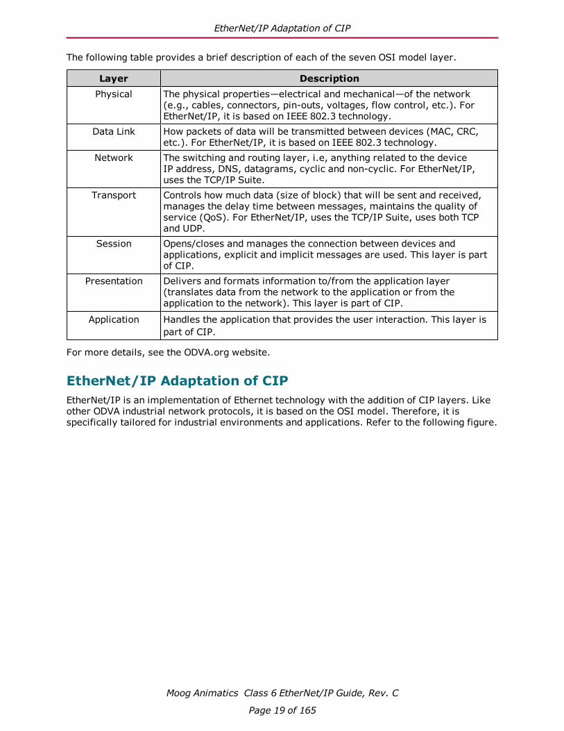
The following table provides a brief description of each of the seven OSI model layer.
Layer DescriptionPhysical The physical properties—electrical and mechanical—of the network
(e.g., cables, connectors, pin-outs, voltages, flow control, etc.). For EtherNet/IP, it is based on IEEE 802.3 technology.
Data Link How packets of data will be transmitted between devices (MAC, CRC, etc.). For EtherNet/IP, it is based on IEEE 802.3 technology.
Network The switching and routing layer, i.e, anything related to the device IP address, DNS, datagrams, cyclic and non-cyclic. For EtherNet/IP, uses the TCP/IP Suite.
Transport Controls how much data (size of block) that will be sent and received, manages the delay time between messages, maintains the quality of service (QoS). For EtherNet/IP, uses the TCP/IP Suite, uses both TCP and UDP.
Session Opens/closes and manages the connection between devices and applications, explicit and implicit messages are used. This layer is part of CIP.
Presentation Delivers and formats information to/from the application layer (translates data from the network to the application or from the application to the network). This layer is part of CIP.
Application Handles the application that provides the user interaction. This layer is part of CIP.
For more details, see the ODVA.org website.
EtherNet/IP Adaptation of CIPEtherNet/IP is an implementation of Ethernet technology with the addition of CIP layers. Like other ODVA industrial network protocols, it is based on the OSI model. Therefore, it is specifically tailored for industrial environments and applications. Refer to the following figure.
Moog Animatics Class 6 EtherNet/IP Guide, Rev. C
Page 19 of 165

EtherNet/IP Adaptation of CIP
Peer-to-peer, multicast, unicast
Ethernet
Internet Protocol (IP)
Transmission Control Protocol (TCP)
User Datagram Protocol (UDP)
Explicit
Messages
Device Pro!les and
Application Objects
Physical
Data Link
Network
Transport
Session
Presentation
Application
Implicit
Messages
IEEE
Standards
TCP/IP
Suite
Common
Industrial
Protocol
(CIP)
OSI
Mo
del
La
yers
OSI Model: EtherNet/IP Implementation
As shown in the previous figure, EtherNet/IP uses two communication protocols for message transport:
l Transmission Control Protocol (TCP) is used for Explicit messages—these are non-cyclic messages for device configuration and setup of cyclic connection content.
l User Datagram Protocol (UDP) is used for Implicit (I/O) messages—these are cyclic messages that handle time-critical control data.
For more details on messages, see Messaging on page 23. Also, see Position Controller Implicit I/O Messages on page 46.
EtherNet/IP is designed to be reliable, easily expanded for future growth, and can theoretically handle an unlimited number of devices. Note, however, that there may be other factors that impose limitations on the size of the network.
For more details, see the ODVA.org website.
Moog Animatics Class 6 EtherNet/IP Guide, Rev. C
Page 20 of 165
Objects
ObjectsThis section briefly describes the features of CIP device objects. For more details, see THE CIP NETWORKS LIBRARY, Volume 1: Common Industrial Protocol (CIP™), which is available on the ODVA.org website.
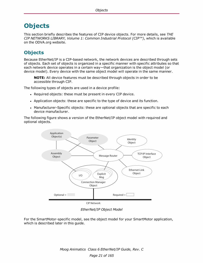
ObjectsBecause EtherNet/IP is a CIP-based network, the network devices are described through sets of objects. Each set of objects is organized in a specific manner with specific attributes so that each network device operates in a certain way—that organization is the object model (or device model). Every device with the same object model will operate in the same manner.
NOTE: All device features must be described through objects in order to be accessible through CIP.
The following types of objects are used in a device profile:
l Required objects: these must be present in every CIP device.
l Application objects: these are specific to the type of device and its function.
l Manufacturer-Specific objects: these are optional objects that are specific to each device manufacturer.
The following figure shows a version of the EtherNet/IP object model with required and optional objects.
CIP Network
Required = Optional =
Assembly
Object
Application
Object(s) Parameter
Object
Message Router
Identity
Object
TCP/IP Interface
Object
Ethernet Link
Object
Connection Manager
Object
I/OExplicit
Msg
EtherNet/IP Object Model
For the SmartMotor-specific model, see the object model for your SmartMotor application, which is described later in this guide.
Moog Animatics Class 6 EtherNet/IP Guide, Rev. C
Page 21 of 165

Classes, Instances and Attributes
Classes, Instances and AttributesThe CIP object model uses classes, instances and attributes to describe each device. Refer to the following figure.
l Class: a fixed collection of objects with each object having a fixed set of attributes. The CIP object library contains three primary object classes: general use, application specific, and network specific.
l Instance: an occurrence of a particular object (in other words, there can be more than one occurrence of the same object but with different attribute values).
l Attributes: a set of data values that describe an object instance (instance attributes). They can also describe an object class (class attributes).
Device Address
Object 2
Instance 1
Object Class 2
Object 1
Instance 2
Object Class 1
Attribute 3
Attribute 2
Attribute 1
Object 1
Instance 1
Attribute 3
Attribute 2
Attribute 1
Classes, Instances, Attributes
The device description (class, instance, attributes) information is also contained in the Electronic Data Sheet (EDS) file, which is supplied by the equipment vendor (see EDS File on page 34).
For more details, see the ODVA.org website.
Moog Animatics Class 6 EtherNet/IP Guide, Rev. C
Page 22 of 165

Messaging
MessagingThere are two types of messages used by EtherNet/IP: explicit messages and implicit messages. Each is described in the following sections.
Explicit (Non-cyclic) MessagesExplicit messages are non-cyclic, i.e., they are typically sent once instead of at regular intervals. Further, explicit messages are not time sensitive. They are used for communicating information such as configuration, diagnostic, data logs, and other information that is not time critical. They can also be used to set up implicit (cyclic) connection content (see the next section).
Explicit messages are point-to-point messages. In other words, a device sends out a message directed to a specific recipient device. The recipient device will return a response to that message. As a result, the explicit messages are much larger than implicit messages (refer to the next section) and can generate a lot of network traffic; therefore, they are not used for transmitting cyclic data.
Implicit (Cyclic) MessagesImplicit messages (also referred to as I/O messages) are cyclic, i.e., they are sent at regular intervals. Implicit messages are used to communicate critical, time-sensitive information. They are typically used for I/O control, PID loop closure, and Motion or Application control.
The implicit message connection between the two devices is established up front and connection ID assignment is made. Therefore, the actual implicit messages contain just the connection ID and the data. As a result, implicit messages are very small, they can travel quickly, and they do not use much network bandwidth.
Explicit/Implicit Messaging ExampleIn the following figure, a tool uses explicit messaging to configure the connections between two network devices. Once that I/O connection is established, the devices can communicate using implicit messaging. For more details, see THE CIP NETWORKS LIBRARY, Volume 1: Common Industrial Protocol (CIP™), which is available on the ODVA.org website.
ToolI/O Connection
Object
Device A
I/O Connection
Object
Device B
I/O Connection
Object
Device A
I/O Connection
Object
Device B
I/O Connection from A to B
(Implicit messaging)
Con!gure connection instance
(Explicit messaging)
Con!gure connection instance
(Explicit messaging)
CO
NF
IGU
RA
TIO
NR
ES
ULT
Explicit/Implicit Messaging Example
Moog Animatics Class 6 EtherNet/IP Guide, Rev. C
Page 23 of 165

Connections, Wiring and Status LEDs
Connections, Wiring and Status LEDsThis chapter provides information on the SmartMotor connectors, a multidrop cable diagram, and a description of the SmartMotor status LEDs.
Connectors and Pinouts 25
M-Style Motor Connectors and Pinouts 25
Moog Animatics Industrial Ethernet Cables 26
M-style to M-style Ethernet Cable 26
M-style to RJ45 Ethernet Cable 26
EtherNet/IP Custom Cable 26
Cable Diagram 27
EtherNet/IP Cable Diagram 27
Status LEDs 28
Moog Animatics Class 6 EtherNet/IP Guide, Rev. C
Page 24 of 165

Connectors and Pinouts
Connectors and Pinouts
M-Style Motor Connectors and PinoutsThe following figure provides a brief overview of the connectors and pinouts available on the M-style SmartMotors.
1
2 3
4POWER INPUT
PIN FUNCTION DESCRIPTION
1 24 VDC CONTROL I/O POWER2 EARTH CHASSIS GROUND3 GND MOTOR COMMON GROUND4 48 VDC MOTOR POWER
COMMUNICATION
PIN FUNCTION
1 GND-COMMON2 RS-485B CH03 RS-485A CH04 ENC A+ (IN/OUT)5 ENC B- (IN/OUT)6 ENC A- (IN/OUT)7 5 VDC OUT8 ENC B+ (IN/OUT)
1
2
3
4
5
6
7
8
1
23
4
5
67
8
9
10
11
12
I/Os
PIN FUNCTION DEFAULT
1 IN0 GENERAL PURPOSE2 IN1 GENERAL PURPOSE3 IN2/POSLIMIT POSITIVE LIMIT4 IN3/NEGLIMIT NEGATIVE LIMIT5 IN/OUT4 GENERAL PURPOSE
6 IN/OUT5 GENERAL PURPOSE
7 IN6 GENERAL PURPOSE
8 IN7-DRVEN DRIVE ENABLE9 OUT8/BRAKE BRAKE OUTPUT10 OUT9-NOFAULT NOT FAULT11 24 VDC OUT* CONTROL I/O POWER12 GND MOTOR COMMON GROUND
INPUT OR OUTPUT
INPUT, DISCRETE OR ANALOG
POSSIBLE (SELECTABLE) FUNCTIONS
INPUT, DISCRETE OR ANALOG INPUT INPUT INPUT/OUTPUT
INPUT/OUTPUT
INPUT
INPUT OUTPUT OUTPUT POWER OUTPUT** N/A
GENERAL PURPOSE GENERAL PURPOSE POSITIVE LIMIT OR GENERAL PURPOSE
NEGATIVE LIMIT OR GENERAL PURPOSE GENERAL PURPOSE, OR EXTERNAL ENCODER INDEX CAPTURE GENERAL PURPOSE, OR INTERNAL ENCODER INDEX CAPTURE GENERAL PURPOSE, G COMMAND, OR HOMING INPUT (ETHERCAT ONLY)
N/A
NOT FAULT BRAKE OUTPUT OR GENERAL-PURPOSE OUTPUT DRIVE ENABLE
*NOTE: 2 AMPS MAX **SUPPLIED FROM POWER INPUT PIN 1
CONTROL I/O POWER
RS-485 serial communication uses a voltage differential signal. Appropriate terminating resistors should be included on the RS-485 network to ensure reliable performance. For details, see the sectionPower and RS-485 Com Multidrop.
1
2
3 4
Shield tied to motorhousing
LED 4: EtherNet/IP Link 1 Port LED
LED 2: EtherNet/IP Network Status LED
LED 0: Motor Drive LED
LED 5: Link EtherNet/IP Link 2 LED
LED 3: EtherNet/IP Module Status LED
LED 1: Motor Busy LED
USB Port LEDSD Card LED
EtherNet/IP
PIN FUNCTION
1 +TX2 +RX3 -TX4 -RX
*Input *Output
NOTE: When daisy-chaining SmartMotors for an EtherNet/IP network, there is no specific IN or OUT Ethernet port. In other words, either Ethernet port can be used for the input or the output.
Moog Animatics Class 6 EtherNet/IP Guide, Rev. C
Page 25 of 165

Moog Animatics Industrial Ethernet Cables
Moog Animatics Industrial Ethernet CablesThe following Industrial Ethernet cables are available from Moog Animatics.
M-style to M-style Ethernet Cable
This cable has M12 male threaded connectors at both ends. It is available in 1, 3, 5 and 10 meter lengths. For the standard cable, use part number CBLIP-ETH-MM-xM, where "x" denotes the cable length. A right-angle version is also available; use part number CBLIP-ETH-MM-xMRA.
M-style to RJ45 Ethernet Cable
This cable has an M12 male threaded connector at one end, and an RJ45 male connector at the opposite end. It is available in 1, 3, 5 and 10 meter lengths. For the standard cable, use part number CBLIP-ETH-MRJ-xM, where "x" denotes the cable length. A right-angle version is also available; use part number CBLIP-ETH-MRJ-xMRA.
EtherNet/IP Custom CableThe following figure provides details for creating a custom shielded EtherNet/IP cable.
NOTE: The motor end of the cable requires an industrial Ethernet connector.
Industrial Ethernet Connector
(Motor end of cable)
PIN
1
2
3
4
+TX
+RX
-TX
-RX
DESCRIPTION
Shield tied to motor housing
RJ45S Connector
(EtherNet/IP master end of cable)
1
2
3
4
5
6
7
8
+TX
-TX
+RX
No Connection
No Connection
-RX
No Connection
No Connection
PIN DESCRIPTION
Shield tied to RJ45S connector
Moog Animatics Class 6 EtherNet/IP Guide, Rev. C
Page 26 of 165

Cable Diagram
Cable DiagramThis section describes the cabling information for adding a SmartMotor to an EtherNet/IP network.
CAUTION: To minimize the possibility of electromagnetic interference (EMI), all connections should use shielded Ethernet Category 5 (Cat 5), or better, cables.
EtherNet/IP Cable DiagramThe following diagram shows an example EtherNet/IP network with the SmartMotors daisy chained to the EtherNet/IP master device. An optional "ring" configuration can be created if the EtherNet/IP master device has two ports.
EtherNet/IP Bus
Other EtherNet/IP device:
- I/O block,
- Servo drive,
- etc.
EtherNet/IP Master
- PC,
- PLC,
- etc.
Moog Animatics
SmartMotor
Moog Animatics
SmartMotor
Optional ring for cable redundancy*
*Ring con!guration requires an EtherNet/IP master with two ports
NOTE: Either Ethernet port can be used
to daisy-chain the motors.
Example Daisy-Chain Con�guration
NOTE: Unlike other fieldbus protocols, EtherNet/IP does not require terminators at each end of the network bus.
Many network configurations are possible, such as line, tree or star. Requirements for specific configurations depend on the capabilities of the EtherNet/IP controller devices, the node devices, types and lengths of cables, and use of other networking equipment. For specific details on creating an EtherNet/IP network, refer to the ODVA publication EtherNet/IP Media Planning and Installation Manual, which is available on the ODVA.org website.
Moog Animatics Class 6 EtherNet/IP Guide, Rev. C
Page 27 of 165
Status LEDs
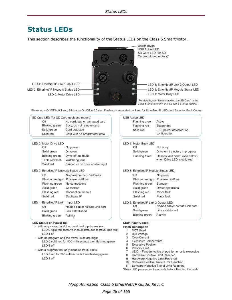
Status LEDsThis section describes the functionality of the Status LEDs on the Class 6 SmartMotor.
Off No power
Solid green Drive on
Blinking green Drive off, no faults
Triple red flash Watchdog fault
Solid red Faulted or no drive enable input
Off Not busy
Solid green Drive on, trajectory in progress
Off No/bad cable; no/bad Link port
Solid green Link established
Flashing # red Flashes fault code* (see below)
when Drive LED is solid red
Blinking green Activity
Off No/bad cable; no/bad Link port
Solid green Link established
Blinking green Activity
Off No power
Flashing red/grn Power-up self test
Flashing green Standby
Solid green Device operational
Flashing red Minor fault
Solid red Major fault
Off No power or no IP address
Flashing red/grn Power-up self test
Flashing green No connections
Solid green Connected
Flashing red Connection timeout
Solid red Duplicate IP
LED 4: EtherNet/IP Link 1 Input LED
LED 2: EtherNet/IP Network Status LED
LED 0: Motor Drive LED
LED 5: EtherNet/IP Link 2 Output LED
LED 3: EtherNet/IP Module Status LED
LED 1: Motor Busy LED
LED 0: Motor Drive LED LED 1: Motor Busy LED
LED 3: EtherNet/IP Module Status LED
LED 5: EtherNet/IP Link 2 Output LED
LED 2: EtherNet/IP Network Status LED
LED 4: EtherNet/IP Link 1 Input LED
LED Status on Power-up:
• With no program and the travel limit inputs are low:
LED 0 solid red; motor is in fault state due to travel limit fault
LED 1 off
• With no program and the travel limits are high:
LED 0 solid red for 500 milliseconds then flashing green
LED 1 off
• With a program that only disables travel limits:
LED 0 red for 500 milliseconds then flashing green
LED 1 off
Flash
1
2
3
4
5
6
7
8
9
10
11
Description
NOT Used
Bus Voltage
Over Current
Excessive Temperature
Excessive Position
Velocity Limit
dE/Dt - First derivative of position error is excessive
Hardware Positive Limit Reached
Hardware Negative Limit Reached
Software Positive Travel Limit Reached
Software Negative Travel Limit Reached
LED1 Fault Codes:
*Busy LED pauses for 2 seconds before flashing the code
Flickering = On/Off in 0.1 sec; Blinking = On/Off in 0.5 sec; Flashing = separated by 1 sec for EtherNet/IP LEDs and 2 sec for Fault Codes
Flashing green Active
Flashing red Suspended
Solid red USB power detected, no
configuration
USB Active LED
Under cover:
USB Active LED
SD Card LED (for SD
Card-equipped motors)*
Blinking green
Busy, do not remove card
Solid green
Card detected
Solid red
Card with no SmartMotor data
SD Card LED (for SD Card-equipped motors)
No card, bad or damaged cardOff
*For details, see “Understanding the SD Card” in the
Class 6 SmartMotor™ Installation & Startup Guide.
Moog Animatics Class 6 EtherNet/IP Guide, Rev. C
Page 28 of 165

EtherNet/IP on Class 6 SmartMotors
EtherNet/IP on Class 6 SmartMotorsThis section provides an overview of the EtherNet/IP communications protocol implementation on the Moog Animatics Class 6 SmartMotor.
EtherNet/IP Implementation 30
EtherNet/IP Identity 30
EtherNet/IP Software Version Numbers 30
Device Profile 30
SmartMotor Device Profile Overview 31
CIP Objects for EtherNet/IP Devices 31
Application Objects for Position Controller Devices 32
Additional Objects 32
EDS File 34
Moog Animatics Class 6 EtherNet/IP Guide, Rev. C
Page 29 of 165

EtherNet/IP Implementation
EtherNet/IP ImplementationThis section describes EtherNet/IP implementation information for the Class 6 SmartMotor.
EtherNet/IP IdentityThe following identity information is available when the SmartMotor is queried by the EtherNet/IP master.
l Product Codes: 10 - SM6-M
l Device Name: Factory data in nonvolatile EEPROM memory.
l Serial Number: Factory data in nonvolatile EEPROM memory.
NOTE: These identity items match those shown on the SmartMotor name plate.
EtherNet/IP Software Version NumbersThe initial EtherNet/IP software release is 6.0.2.23.
Device ProfileThe Class 6 EtherNet/IP SmartMotor profile uses the Position Controller (0x10) device. For Position Controller details, see SmartMotor Device Profile Overview on page 31.
Moog Animatics Class 6 EtherNet/IP Guide, Rev. C
Page 30 of 165

SmartMotor Device Profile Overview
Moog Animatics Class 6 EtherNet/IP Guide, Rev. C
Page 31 of 165
SmartMotor Device Profile OverviewThis section provides an overview of the objects used in the SmartMotor device profile. It includes: CIP required objects and network objects (the CIP objects), ODVA "Device" set of objects (the Application objects), and Moog Animatics vendor-specific objects (the Additional objects).
For a full description of each object, see the corresponding "For details..." section. For more details on the Position Controller Device, see Position Controller Device (0x10) on page 44.
CIP Objects for EtherNet/IP DevicesThe following table shows the minimum objects required for any EtherNet/IP device.
Object Class ClassCode Description Required/
Optional Instances For details, see...
Identity Object 0x01 Provides identification and general device information. Object is required in every network device.
Required 1 Identity Object (0x01) on page 65
Message Router Object
0x02 Provides message handling for communicating with objects in the physical device.
Required 1 Message Router Object (0x02) on page 69
Assembly Object
0x04 Binds attributes of multiple objects, allowing data to/from each object to be sent/received through a single connection. Also used to bind input or output data.
Optional - used for the SmartMotor
2 Assembly Object (0x04) on page 70
Connection Manager Object
0x06 Establishes and manages the communications connections (exchanges of messages), including connections across multiple subnets.
Conditional (required for EtherNet/IP)
1 Connection Man-ager Object (0x06) on page 71
TCP/IP Interface Object1
0xF5 Configures the device’s TCP/IP network interface. For example, this includes the device’s IP Address, Network Mask, and Gateway Address.
Conditional (required for EtherNet/IP)
1 TCP/IP Interface Object (0xF5) on page 72

Application Objects for Position Controller Devices
Moog Animatics Class 6 EtherNet/IP Guide, Rev. C
Page 32 of 165
Object Class ClassCode Description Required/
Optional Instances For details, see...
Ethernet Link Object1
0xF6 Maintains link-specific counters and status information for the communications interface.
Conditional (required for EtherNet/IP)
1 Ethernet Link Object (0xF6) on page 79
1. Network-Specific Link Objects
Application Objects for Position Controller DevicesThe Position Controller Device type is 0x10; there is one instance. The following table shows the required application objects for a Position Controller device.
Object Class ClassCode Description Required/
Optional Instances For details,see...
CIP Required Objects
(seeprevioustable)
(see previous table) Required (see previous
table)
(see previous table)
Position Controller Supervisor
0x24 Handles errors for Position Controller, also home and registration inputs.
Required 1 Position Controller Supervisor (0x24) on page 86
Position Controller
0x25 Performs control output velocity profiling; handles input/output to/from the motor, limit switches registration, etc.
Required 1 Position Controller (0x25) on page 88
Additional ObjectsIn addition to the object classes in the previous tables, the following manufacturer-specific and other objects have been added for the SmartMotor.
Object Class ClassCode
Description Required/Optional
Instances For details, see...
Device Level Ring (DLR) Object
0x47 Allows use of an Ethernet ring network topology
1 Device Level Ring (DLR) Object (0x47) on page 94
Quality of Ser-vice (QOS) Object
0x48 Provides priority-depend-ent control of the Eth-ernet data streams.
1 QoS Object (0x48) on page 96

Additional Objects
Moog Animatics Class 6 EtherNet/IP Guide, Rev. C
Page 33 of 165
Object Class ClassCode
Description Required/Optional
Instances For details, see...
SmartMotor I/O Object
0x71 Manufacturer-specific object associated with the Position Controller Device
1 SmartMotor I/O Object (0x71) on page 98
EDS File
Moog Animatics Class 6 EtherNet/IP Guide, Rev. C
Page 34 of 165
EDS FileThe Electronic Data Sheet (EDS) file is supplied by the equipment manufacturer. It is an ASCII text file that is structured as specified by the CIP specification. The EDS file contains all of the necessary information for the configurable parameters of the corresponding device (i.e., it contains information required by the CIP specification and may include vendor-specific information provided by the manufacturer). For example, there is an EDS file supplied by Moog Animatics for the EtherNet/IP SmartMotor.
All CIP network configuration tools have the ability to read EDS files. The information in the EDS file is used by the configuration tool to guide the user through the configuration process.
For more details, see THE CIP NETWORKS LIBRARY, Volume 1: Common Industrial Protocol (CIP™), which is available on the ODVA.org website.
To obtain the EDS file for the SmartMotor:
1. Access the Download Center on the Moog Animatics website at:
http://www.animatics.com/support/download-center.html
2. From the folder list, select Firmware And Fieldbus Downloads > Fieldbus Config > EtherNet/IP folder.
3. Locate the EDS file (.eds extension) and click it.
4. Save the file to a location on your computer.

EtherNet/IP User Program Commands
EtherNet/IP User Program CommandsThis chapter provides details on the EtherNet/IP commands used with the SmartMotor and its user program. SmartMotor programming is described in the SmartMotor™ Developer's Guide. The SmartMotor user program allows the motor to take on autonomous or distributed control functions needed in an application.
Network Settings and Status Commands 36
Combitronic Addressing over Ethernet (UDP) 41
Program Example 41
Status and Diagnostic Codes 42
Status/Error Codes 42
Diagnostic Codes 42
Moog Animatics Class 6 EtherNet/IP Guide, Rev. C
Page 35 of 165

Network Settings and Status Commands
Network Settings and Status CommandsThe SmartMotor's EEPROM can store nonvolatile EtherNet/IP information about the network. For proper EtherNet/IP operation, each SmartMotor must have a unique IP address. If a DHCP server is used in the network, then the SmartMotor default IP address (0.0.0.0) is used; if a fixed IP address is needed or there is no DHCP server, the IP address can be set using the IPCTL command. This can be accomplished: at the PLC over EtherNet/IP; with SMI and a USB connection, or RS-485 on channel 0; with a SmartMotor user program. If an IP address is assigned through any method, including the DHCP server, that address is stored and used at the next power-up.
NOTE: Nonvolatile memory will be read at power-up or after the Z (reset) command has been executed.
The commands in the following table are related to the network settings and status.
Command Description/Parameter Values
Non-Volatile Setting
IPCTL(action,"string") action=0: set IP address1: set Mask2: set Gateway
The drive is shipped out-of-box with an IP Address of 0.0.0.0. This address enables DHCP support for addressing. The DHCP server manages the IP Address assigned to the drive.
If a value other than 0.0.0.0 is assigned then DHCP is disabled and the static IP Address is used. Assigning an IP Address of 0.0.0.0 will re-enable DHCP if desired
Value is formatted as an IP address entered as a string, e.g., IPCTL(0,"192.168.0.10"). By default, these values are set to 0 (i.e., "0.0.0.0")
NOTE: The drive must be power cycled or reset using a "Z" terminal window command before the new IP Address takes affect.
YES
RETH(0), or x=ETH(0)
RETH i s the same as RETH(0)
x=ETH is the same as x=ETH(0)
EtherNet/IP status Bit 0 = Initialization failureBit 1 = Configuration changeBit 2 = ReservedBit 3 = Network processor failureBit 4 = ReservedBit 5 = Reserved
N/A
RETH(1), or x=ETH(1)
Module status 0 = No power1 = Self test2 = Standby3 = Device operational4 = Minor (recoverable) fault5 = Major (non-recoverable) fault
RETH(2), or x=ETH(2)
Network status 0 = Not powered, no IP address1 = No connections2 = Connected3 = Connection timeout4 = Duplicate IP5 = Self-test
Moog Animatics Class 6 EtherNet/IP Guide, Rev. C
Page 36 of 165

Network Settings and Status Commands
Command Description/Parameter Values
Non-Volatile Setting
RETH(3), or x=ETH(3)
Stack fault code For details, see Status and Dia-gnostic Codes on page 42.
RETH(5), or x=ETH(5)
LFW firmware version Firmware version as 32-bit inter-ger. E.g., 3.1.0.1 would be a value 50397185 (0x03010001).
RETH(6), or x=ETH(6)
Network Lost user program num-ber
The current Network Lost program label number.
RETH(7), or x=ETH(7)
Processor type -1 = Failed 0 = Unknown 1 = netX 10 2 = netX 50 3 = netX 51/52 4 = netX 100
RETH(8), or x=ETH(8)
Protocol type 0 = Not defined 1 = PROFINET 2 = EtherCAT 3 = EtherNet/IP
RETH(9), or x=ETH(9)
Network Lost action The current value assigned to the Network Lost action.
RETH(14) [Moog internal use]
RETH(15) IP address Value is in dotted-decimal format.
RETH(16) Subnet mask Value is in dotted-decimal format.
RETH(17) Gateway Value is in dotted-decimal format.
RETH(18) MAC ID string formatted report only
E.g., 00:01:02:a9:ff:00
RETH(19), or x=ETH(19)
Report the detected LFW Pro-tocolClass. This gives a wider range of values than the known and supported protocols listed in ETH (8). Values designated accord-ing to NXF/LFW file loaded into net-work processor and too numerous to list here. These are the values for the supported protocols: (intro-duced in firmware 6.0.2.41 or later)
0 Not Defined21 PROFIBUS9 EtherCAT10 EtherNet/IP... ...
RETH(30), or x=ETH(30)
I/O read data size Value is configured by the master.
RETH(31), or x=ETH(31)
I/O write data size Value is configured by the master.
RETH(45), or x=ETH(45)
IP address as integer E.g., for an IP address of 192.168.1.3 (C0 A8 01 03 hex), this command reports -1062731517 (it reports as a 32-bit signed value).
RETH(46), or x=ETH(46)
IP subnet mask as integer E.g., for an IP netmask of 255.255.0.0 (FF FF 00 00 hex), this command reports -65536 (it reports as a 32-bit signed value).
Moog Animatics Class 6 EtherNet/IP Guide, Rev. C
Page 37 of 165
Network Settings and Status Commands
Command Description/Parameter Values
Non-Volatile Setting
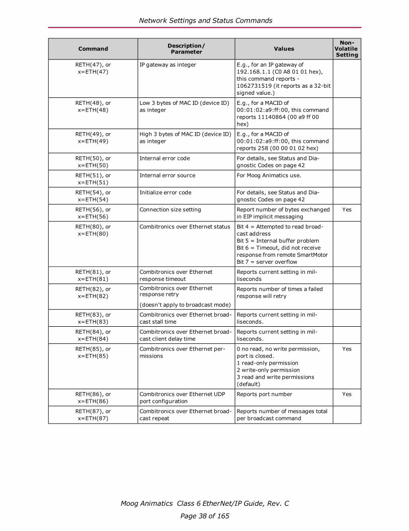
RETH(47), or x=ETH(47)
IP gateway as integer E.g., for an IP gateway of 192.168.1.1 (C0 A8 01 01 hex), this command reports -1062731519 (it reports as a 32-bit signed value.)
RETH(48), or x=ETH(48)
Low 3 bytes of MAC ID (device ID) as integer
E.g., for a MACID of 00:01:02:a9:ff:00, this command reports 11140864 (00 a9 ff 00 hex)
RETH(49), or x=ETH(49)
High 3 bytes of MAC ID (device ID) as integer
E.g., for a MACID of 00:01:02:a9:ff:00, this command reports 258 (00 00 01 02 hex)
RETH(50), or x=ETH(50)
Internal error code For details, see Status and Dia-gnostic Codes on page 42
RETH(51), or x=ETH(51)
Internal error source For Moog Animatics use.
RETH(54), or x=ETH(54)
Initialize error code For details, see Status and Dia-gnostic Codes on page 42
RETH(56), or x=ETH(56)
Connection size setting Report number of bytes exchanged in EIP implicit messaging
Yes
RETH(80), or x=ETH(80)
Combitronics over Ethernet status Bit 4 = Attempted to read broad-cast addressBit 5 = Internal buffer problemBit 6 = Timeout, did not receive response from remote SmartMotorBit 7 = server overflow
RETH(81), or x=ETH(81)
Combitronics over Ethernet response timeout
Reports current setting in mil-liseconds
RETH(82), or x=ETH(82)
Combitronics over Ethernet response retry
(doesn't apply to broadcast mode)
Reports number of times a failed response will retry
RETH(83), or x=ETH(83)
Combitronics over Ethernet broad-cast stall time
Reports current setting in mil-liseconds.
RETH(84), or x=ETH(84)
Combitronics over Ethernet broad-cast client delay time
Reports current setting in mil-liseconds.
RETH(85), or x=ETH(85)
Combitronics over Ethernet per-missions
0 no read, no write permission, port is closed.1 read-only permission2 write-only permission3 read and write permissions (default)
Yes
RETH(86), or x=ETH(86)
Combitronics over Ethernet UDP port configuration
Reports port number Yes
RETH(87), or x=ETH(87)
Combitronics over Ethernet broad-cast repeat
Reports number of messages total per broadcast command
Moog Animatics Class 6 EtherNet/IP Guide, Rev. C
Page 38 of 165

Network Settings and Status Commands
Command Description/Parameter Values
Non-Volatile Setting
RETH(100), or x=ETH(100)
TCP Serial connection encap-sulation permissions
Reports one of the following values:
0 disabled TCP communications port and UDP discovery port1 enabled TCP communications port only2 enabled UDP discovery port only3 enabled TCP communications port and UDP discovery port
RETH(101), or x=ETH(101)
Modbus TCP access permissions Reports one of the following values:
0 no read, no write permission, and TCP port is closed1 read-only2 write-only3 read and wite allowed
ETHCTL(3,x) Reset error code Resets Stack Fault code RETH(3) to 0
ETHCTL(6,<value>) Network Lost user program label number
This setting is nonvolatile.
Program label to jump to if the Network Lost action, ETHCTL(9,<value>), is either set to 4 or 5.
ETHCTL(9,<value>) Network Lost action This setting is nonvolatile.
0 – Ignore, no action (default setting)1 – Send OFF command to motor (servo off)2 – Send X command to motor (smooth stop)3 – Send S command to motor (hard stop)4 – Send GOSUB(x) command, where x is the value of the user program label as defined by ETHCTL(6,<value>).5 – Send GOTO(x) command, where x is the value of the user program label as defined by ETHCTL(6,<value>).
NOTE: Loss of network is an edge-triggered event if I/O Control goes from RUN to any other state.
ETHCTL(45,x) Set IP address as integer E.g., to set for an IP address of 192.168.1.3 (C0 A8 01 03 hex), x=3232235779
Yes
ETHCTL(46,x) Set IP subnet mask as integer E.g., to set for an IP netmask of 255.255.0.0 (FF FF 00 00 hex), x=4294901760
Yes
ETHCTL(47,x) Set IP gateway as integer E.g., to set for an IP gateway of 192.168.1.1 (C0 A8 01 01 hex), x=3232235777
Yes
ETHCTL(50,x) Reset error code Resets Internal Error code RETH(50) and Internal Error source RETH(51) to 0
ETHCTL(51,x) Reset error code Resets Internal Error code RETH(50) and Internal error source RETH(51) to 0
Moog Animatics Class 6 EtherNet/IP Guide, Rev. C
Page 39 of 165

Network Settings and Status Commands
Command Description/Parameter Values
Non-Volatile Setting
ETHCTL(56,x) Connection size setting Set number of bytes exchanged in EIP implicit messaging . Values 8 and 32 supported. Value 0 will con-figure motor to autodetect bytes 8 or 32.
Yes
ETHCTL(80,x) Reset Combitronics error bits Resets Combitronics over Ethernet error code RETH(80) to 0
ETHCTL(81,x) Combitronics over Ethernet response timeout
x in milliseconds, default is 30. Range 1 to 1000.
ETHCTL(82,x) Combitronics over Ethernet response retry
(doesn't apply to broadcast mode)
x in number of times a retry will be allowed before giving up with timeout status. Default is 3. Range is 0 to 10.
ETHCTL(83,x) Combitronics over Ethernet broad-cast stall time
x in milliseconds, default is 10. Range 5 to 100.
Note: may affect ETHCTL(84,x) to enforce that value is less than or equal to this value.
ETHCTL(84,x) Combitronics over Ethernet broad-cast client delay time
x in milliseconds, default is 0. Range 0 to 20.
Note: limited to be less than or equal to ETHCTL(83,x)
ETHCTL(85,x) Combitronics over Ethernet per-missions
x is:
-1 Set to default0 no read, no write permission, close port.1 read-only permission2 write-only permission3 read and write permissions (default)
Yes
ETHCTL(86,x) Combitronics over Ethernet UDP port configuration
x is port number, default is 43500. Range is 1024 to 65535.
Yes
ETHCTL(87,x) Combitronics over Ethernet broad-cast repeat
x is total number of messages per broadcast command, default is 3. Range is 1 to 7.
ETHCTL(100,x) TCP Serial connection encap-sulation permissions
x is:
-1 Set to default0 disable TCP communications port and UDP discovery port1 enable TCP communications port only2 enable UDP discovery port only3 enable TCP communications port and UDP discovery port
Yes
ETHCTL(101,x) Modbus TCP access permissions x is:
-1 Set to default0 no read, no write permission, close port.1 read-only permission2 write-only permission3 read and write permissions (default)
Yes
Moog Animatics Class 6 EtherNet/IP Guide, Rev. C
Page 40 of 165
Combitronic Addressing over Ethernet (UDP)
Command Description/Parameter Values
Non-Volatile Setting
ETHCTL(110,x) TCP Serial connection encap-sulation keepalive interval
x is:
-1 Set to default0 disableRange 1-127 seconds
Default is 3 seconds.
Yes
ETHCTL(111,x) Modbus TCP keepalive interval x is:
-1 Set to default0 disableRange 1-127 seconds
Default is 3 seconds.
Yes
RGROUP(function), or x=GROUP(function)
Combitronic over Ethernet group addressing: report current setting
See the SmartMotor Developer's Guide.
GROUP(function,value) Combitronic over Ethernet group addressing: apply setting
See the SmartMotor Developer's Guide.
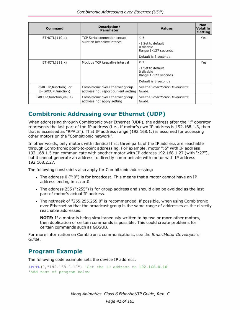
Combitronic Addressing over Ethernet (UDP)When addressing through Combitronic over Ethernet (UDP), the address after the ":" operator represents the last part of the IP address (i.e., if motor’s own IP address is 192.168.1.3, then that is accessed as "RPA:3"). That IP address range (192.168.1.) is assumed for accessing other motors on the "Combitronic network".
In other words, only motors with identical first three parts of the IP address are reachable through Combitronic point-to-point addressing. For example, motor ":5" with IP address 192.168.1.5 can communicate with another motor with IP address 192.168.1.27 (with ":27"), but it cannot generate an address to directly communicate with motor with IP address 192.168.2.27.
The following constraints also apply for Combitronic addressing:
l The address 0 (":0") is for broadcast. This means that a motor cannot have an IP address ending in x.x.x.0.
l The address 255 (":255") is for group address and should also be avoided as the last part of motor's actual IP address.
l The netmask of "255.255.255.0" is recommended, if possible, when using Combitronic over Ethernet so that the broadcast group is the same range of addresses as the directly reachable addresses.
NOTE: If a motor is being simultaneously written to by two or more other motors, then duplication of certain commands is possible. This could create problems for certain commands such as GOSUB.
For more information on Combitronic communications, see the SmartMotor Developer's Guide.
Program ExampleThe following code example sets the device IP address.
IPCTL(0,"192.168.0.10") 'Set the IP address to 192.168.0.10'Add rest of program below
Moog Animatics Class 6 EtherNet/IP Guide, Rev. C
Page 41 of 165
Status and Diagnostic Codes
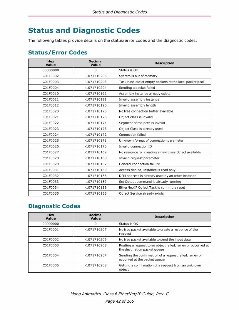
Status and Diagnostic CodesThe following tables provide details on the status/error codes and the diagnostic codes.
Status/Error CodesHex
ValueDecimalValue Description
00000000 0 Status is OK
C01F0002 -1071710206 System is out of memory
C01F0003 -1071710205 Task runs out of empty packets at the local packet pool
C01F0004 -1071710204 Sending a packet failed
C01F0010 -1071710192 Assembly instance already exists
C01F0011 -1071710191 Invalid assembly instance
C01F0012 -1071710190 Invalid assembly length
C01F0020 -1071710176 No free connection buffer available
C01F0021 -1071710175 Object class is invalid
C01F0022 -1071710174 Segment of the path is invalid
C01F0023 -1071710173 Object Class is already used
C01F0024 -1071710172 Connection failed
C01F0025 -1071710171 Unknown format of connection parameter
C01F0026 -1071710170 Invalid connection ID
C01F0027 -1071710169 No resource for creating a new class object available
C01F0028 -1071710168 Invalid request parameter
C01F0029 -1071710167 General connection failure
C01F0031 -1071710159 Access denied, instance is read only
C01F0032 -1071710158 DPM address is already used by an other instance
C01F0033 -1071710157 Set Output command is already running
C01F0034 -1071710156 EtherNet/IP Object Task is running a reset
C01F0035 -1071710155 Object Service already exists
Diagnostic CodesHex
ValueDecimalValue Description
00000000 0 Status is OK
C01F0001 -1071710207 No free packet available to create a response of the request
C01F0002 -1071710206 No free packet available to send the input data
C01F0003 -1071710205 Routing a request to an object failed; an error occurred at the destination packet queue
C01F0004 -1071710204 Sending the confirmation of a request failed; an error occurred at the packet queue
C01F0005 -1071710203 Getting a confirmation of a request from an unknown object
Moog Animatics Class 6 EtherNet/IP Guide, Rev. C
Page 42 of 165
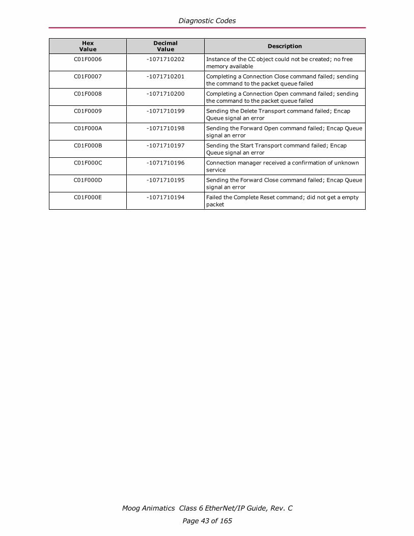
Diagnostic Codes
HexValue
DecimalValue Description
C01F0006 -1071710202 Instance of the CC object could not be created; no free memory available
C01F0007 -1071710201 Completing a Connection Close command failed; sending the command to the packet queue failed
C01F0008 -1071710200 Completing a Connection Open command failed; sending the command to the packet queue failed
C01F0009 -1071710199 Sending the Delete Transport command failed; Encap Queue signal an error
C01F000A -1071710198 Sending the Forward Open command failed; Encap Queue signal an error
C01F000B -1071710197 Sending the Start Transport command failed; Encap Queue signal an error
C01F000C -1071710196 Connection manager received a confirmation of unknown service
C01F000D -1071710195 Sending the Forward Close command failed; Encap Queue signal an error
C01F000E -1071710194 Failed the Complete Reset command; did not get a empty packet
Moog Animatics Class 6 EtherNet/IP Guide, Rev. C
Page 43 of 165

Position Controller Device (0x10)
Position Controller Device (0x10)This chapter provides information on the Position Controller Device (0x10). For more details, see THE CIP NETWORKS LIBRARY, Volume 1: Common Industrial Protocol (CIP™), which is available on the ODVA.org website.
Position Controller Device Application Objects 45
Position Controller Device Object Model 45
Position Controller Implicit I/O Messages 46
General Command and Response Message Types 46
Attribute GET/SET Command Types 0x1A and 0x1B 51
Error Response Message Type (0x14) 52
Semantics for Command and Response Messages 53
Position Controller I/O Handshaking 56
Profile Moves 57
Torque Command 58
Control Mode Change - Change Dynamic 58
Position Controller Implicit I/O Message Examples 59
SmartMotor Notes 59
Set Acceleration 59
Set Velocity, Leave Drive ON 60
Set Target Position, Perform Move 60
Disable Hardware Limits (Object 0x25, Attribute 49) 60
Extended Position Move (32-byte frame) 61
Moog Animatics Class 6 EtherNet/IP Guide, Rev. C
Page 44 of 165

Position Controller Device Application Objects
Position Controller Device Application ObjectsThe following table shows the application objects for the Position Controller device and describes their functions. For a full description of each object, see the corresponding "For details..." section.
Object Class ClassCode Description Required/
Optional Instances For details,see...
Position Controller Supervisor
0x24 Handles errors for the Position Controller as well as Home and Registration inputs.
Required 1 Position Controller Supervisor (0x24) on page 86
Position Controller
0x25 Performs the control output velocity profiling and handles input and output to and from the motor drive unit, limit switches registration etc.
Required 1 Position Controller (0x25) on page 88
Note that these objects are the Application Objects in the overall SmartMotor device profile. For a listing of all objects in the device profile used for the SmartMotor, see SmartMotor Device Profile Overview on page 31.
Position Controller Device Object ModelThe following figure provides a diagram of the Position Controller Device object model.
CIP Network
Required =
Message Router
Identity
Object
Network Speci!c
Link Object(s)
I/O
Msg*
Explicit
Msg
Optional =
Position Controller
Supervisor Object
Postion
Controller
Supervisor
Position
Controller
Object
Axis Objects
Connection
*NOTES:
Consumed Connection Path:
Position Controller Supervisor class
Consumed Command Message attribute
Produced Connection Path:
Position Controller Supervisor class
Produced Command Message attribute
Position Controller Device Object Model
Moog Animatics Class 6 EtherNet/IP Guide, Rev. C
Page 45 of 165

Position Controller Implicit I/O Messages
Moog Animatics Class 6 EtherNet/IP Guide, Rev. C
Page 46 of 165
Position Controller Implicit I/O Messages This section describes the details about implicit I/O messages for the device.
General Command and Response Message TypesThis section describes the formats for consumed and produced general messages.
l The standard CIP Position Controller I/O connection messages are 8-byte messages.
l The Class 6 EtherNet/IP SmartMotor supports both the standard 8-byte format and an extended 32-byte format.
l The first eight bytes of the 32-byte format match the 8-byte format defined in the ODVA CIP Position Controller specification. The SmartMotor will select which message format to use based on the host controller connection size.
Connection Size Description
8 bytes The motor will use the CIP standard communication format and Command Mes-sage Types
32 bytes The motor will use:
l CIP Standard 8 byte messages
l Additional Data Fields in the Command / Response Message frames
l Extended Command Message Types 6 (Position Move) & 7 (Velocity Move)
Any other The motor will respond with an error
The default connection size used in the Class 6 EtherNet/IP SmartMotor EDS file is 32-bytes.
To change the configuration, see ETHCTL(56,x) on page 40; to report the configured value, see RETH(56), or x=ETH(56) on page 38
NOTE: Implicit I/O messages are the most efficient method of exchanging cyclic data, such as Target Position and Actual Position, with the SmartMotor. These message types for the Position Controller Polled I/O Connection are typically the best choice for commanding the SmartMotor shaft position or applied torque.
Polled I/O: Consumed General Message Format
Moog Animatics Class 6 EtherNet/IP Guide, Rev. C
Page 47 of 165
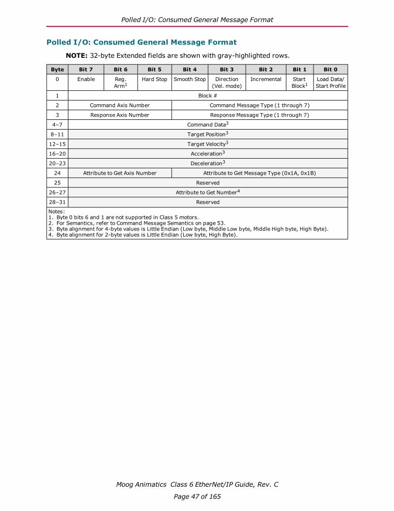
Polled I/O: Consumed General Message Format
NOTE: 32-byte Extended fields are shown with gray-highlighted rows.
Byte Bit 7 Bit 6 Bit 5 Bit 4 Bit 3 Bit 2 Bit 1 Bit 0
0 Enable Reg.Arm1
Hard Stop Smooth Stop Direction(Vel. mode)
Incremental Start Block1
Load Data/Start Profile
1 Block #
2 Command Axis Number Command Message Type (1 through 7)
3 Response Axis Number Response Message Type (1 through 7)
4–7 Command Data3
8–11 Target Position3
12–15 Target Velocity3
16–20 Acceleration3
20–23 Deceleration3
24 Attribute to Get Axis Number Attribute to Get Message Type (0x1A, 0x1B)
25 Reserved
26–27 Attribute to Get Number4
28–31 Reserved
Notes:1. Byte 0 bits 6 and 1 are not supported in Class 5 motors.2. For Semantics, refer to Command Message Semantics on page 53.3. Byte alignment for 4-byte values is Little Endian (Low byte, Middle Low byte, Middle High byte, High Byte). 4. Byte alignment for 2-byte values is Little Endian (Low byte, High Byte).

Polled I/O: Produced General Message Format
Moog Animatics Class 6 EtherNet/IP Guide, Rev. C
Page 48 of 165
Polled I/O: Produced General Message Format
NOTE: 32-byte Extended fields are shown with gray-highlighted rows.
Byte Bit 7 Bit 6 Bit 5 Bit 4 Bit 3 Bit 2 Bit 1 Bit 0
0 Enable Reg. Level1
HomeLevel1
CurrentDirection
General Fault
On Target Position
Block inExecution1
Profile inProgress
1 Block #
2 Load Complete
BlockFault1
Following Error Fault
Negative Limit
Positive Limit
Reverse Limit
Forward Limit
Fault Input1,2
3 Response Axis Number Response Message Type (1 through 5)
4–7 Response Data4
8–11 Actual Position4
12–15 Actual Velocity4
16–19 Reserved
20 Attribute to Get Axis Number Attribute to Get Message Type (0x1A, 0x1B)
21 Reserved
22–23 Attribute to Get Number5
24–27 Attribute to Get Data
No data if Attribute to Get Axis Number and Message Type are zero
28–31 Reserved
Notes:1. Not supported.2. Byte 2 bit 0 can be configured as the Servo Bus Voltage Okay status.3. For semantics, refer to Response Message Semantics on page 54. 4. Byte alignment for 4-byte values is Little Endian (Low byte, Middle Low byte, Middle High byte, High Byte). 5. Byte alignment for 2-byte values is Little Endian (Low byte, High Byte).
General Command / Response Message Types
Command / Response
Message TypeCommand Data Response Data
Class 0x25 Attr #3
Mode Setting
1a Target Position Actual Position 0
2a Target Velocity Command Position 1
3 Acceleration Actual Velocity N/A
4 Deceleration Command Velocity N/A
5a Torque Torque 2
6a,bPosition Profile
Move - See description below
N/A 0
7a,bVelocity Profile
Move - See description below
N/A 1
Notes:a. The drive Control Mode must match the desired command type in order to start a profile move or apply torque.b. Only available for 32-byte connections.
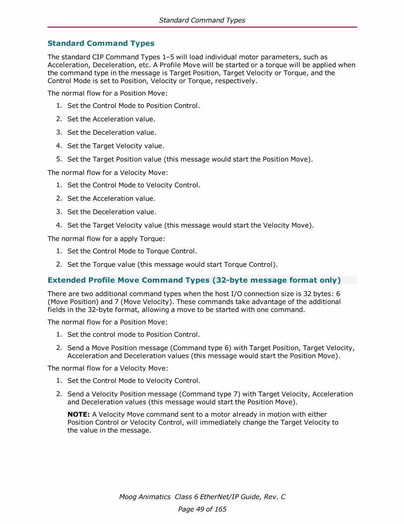
Standard Command Types
Moog Animatics Class 6 EtherNet/IP Guide, Rev. C
Page 49 of 165
Standard Command Types
The standard CIP Command Types 1–5 will load individual motor parameters, such as Acceleration, Deceleration, etc. A Profile Move will be started or a torque will be applied when the command type in the message is Target Position, Target Velocity or Torque, and the Control Mode is set to Position, Velocity or Torque, respectively.
The normal flow for a Position Move:
1. Set the Control Mode to Position Control.
2. Set the Acceleration value.
3. Set the Deceleration value.
4. Set the Target Velocity value.
5. Set the Target Position value (this message would start the Position Move).
The normal flow for a Velocity Move:
1. Set the Control Mode to Velocity Control.
2. Set the Acceleration value.
3. Set the Deceleration value.
4. Set the Target Velocity value (this message would start the Velocity Move).
The normal flow for a apply Torque:
1. Set the Control Mode to Torque Control.
2. Set the Torque value (this message would start Torque Control).
Extended Profile Move Command Types (32-byte message format only)
There are two additional command types when the host I/O connection size is 32 bytes: 6 (Move Position) and 7 (Move Velocity). These commands take advantage of the additional fields in the 32-byte format, allowing a move to be started with one command.
The normal flow for a Position Move:
1. Set the control mode to Position Control.
2. Send a Move Position message (Command type 6) with Target Position, Target Velocity, Acceleration and Deceleration values (this message would start the Position Move).
The normal flow for a Velocity Move:
1. Set the Control Mode to Velocity Control.
2. Send a Velocity Position message (Command type 7) with Target Velocity, Acceleration and Deceleration values (this message would start the Position Move).
NOTE: A Velocity Move command sent to a motor already in motion with either Position Control or Velocity Control, will immediately change the Target Velocity to the value in the message.

Extended Attribute to Get (32-byte message format only)
Moog Animatics Class 6 EtherNet/IP Guide, Rev. C
Page 50 of 165
Extended Attribute to Get (32-byte message format only)
The 32-byte format also has fields allowing the Class 6 SmartMotor to send parameter data back to the controller independent of the Command and Response Message types set in the first eight bytes.
l When the "Attribute to Get Message Type" field is set to 26 (0x1A - Position Controller Supervisor) or 27 (0x1B - Position Controller) the motor will return the value of the Object Attribute specified in field "Attribute to Get Number" (bytes 26-27). The value will be returned in the "Attribute to Get Data" field of the response (bytes 24 - 27).
l If there are any errors in the request, the motor will respond with:
o A Message Type of 0x14 in the Attribute to Get Message Type field of the response
o The General Error Code in byte 24 of the response
o The Additional Error Code in byte 25 of the response
o A value of 0x00 in byte 26 of the response
o A copy of the Attribute to Get Axis Number / Message Type (byte 24) from the request in byte 27 of the response
l When the "Attribute to Get Message Type" field is set to a value of zero, the motor will set the entire "Attribute to Get" structure and "Attribute to Get Data" of the response (bytes 20 -27) to zeroes.
The general flow when using the Extended Attribute to Get fields: (Assumes the Attribute to Get fields start out loaded with 0x00).
1. Load the "Attribute to Get Number" with the desired Attribute Number.
2. Load the "Attribute to Get Axis Number" with a value of 0 or 1.
3. Load the "Attribute to Get Message Type" with the number for the desired object 0x1A (Position Controller Supervisor) or 0x1B (Position Controller).
4. Wait for the "Attribute to Get Message Type" and "Attribute to Get Number" in the response to match the requested values. If the "Attribute to Get Message Type" becomes 0x14 there is an error in the request, follow the logic for errors in section Error Response Message Type (0x14) on page 52.
5. When the "Attribute to Get Message Type" and "Attribute to Get Number" match the requested values, process the data in the response.
6. Clear the "Attribute to Get Message Axis Number / Type" and "Attribute to Get Number" values to values of 0x00.
7. Wait for the "Attribute to Get Message Type" field changes to zero in the response.
The motor will respond with the current value of the requested Attribute to Get each time the motor processes the I/O message independent of the Implicit Message handshaking.

Attribute GET/SET Command Types 0x1A and 0x1B
Moog Animatics Class 6 EtherNet/IP Guide, Rev. C
Page 51 of 165
Attribute GET/SET Command Types 0x1A and 0x1BThis section describes the formats for consumer and producer GET/SET messages. These message types allow the set and get services of the Position Controller Supervisor(type 0x1A) and Position Controller(type 0x1B) classes and their objects attributes. This is a form of indirect addressing over the Polled I/O Connection instead of using an Explicit Connection transfer.
Polled I/O: Consumed Message Format
Byte Bit 7 Bit 6 Bit 5 Bit 4 Bit 3 Bit 2 Bit 1 Bit 0
0 Enable Reg. Arm1
Hard Stop Smooth Stop
Direction(Vel. mode)
Incremental Start Block1
Load Data/Start Profile
1 Attribute Number to GET
2 Command Axis Number Command Message Type (0x1A or 0x1B)
3 Attribute Number to SET
4 Command (SET) Data Low Byte
5 Data Middle Low
6 Data Middle High
7 Command Data High Byte
Notes:1. Byte 0 bits 6 and 1 are not supported Class 5 motors.2. For Semantics, refer to Command Message Semantics on page 53.
Polled I/O: Produced Message Format
Byte Bit 7 Bit 6 Bit 5 Bit 4 Bit 3 Bit 2 Bit 1 Bit 0
0 Enable Reg.Level2
Home Level2 CurrentDirection
General Fault
On Target Position
Block inExecution2
Profile inProgress
1 GET Attribute Number for the Response Data
2 Load Complete
BlockFault2
Following Error Fault
Negative Limit
Positive Limit
Reverse Limit
Forward Limit
Fault Input Fault1
3 Response Axis Number Response Message Type (0x1A or 0x1B)
4 Response (GET) Data Low Byte
5 Data Middle Low
6 Data Middle High
7 Response Data High Byte
Notes:1. Byte 2 bit 0 can be configured as the Servo Bus Voltage Okay status.2. Not supported.3. For Semantics, refer to Response Message Semantics on page 54.
Attribute Message Types
NOTE: See byte 3 in the previous tables.
Message Type
Class Number Class Description Command Data Response Data
26(0x1A) 36(0x24) Position Controller Supervisor Attribute Value to Set Attribute Value to Get27(0x1B) 37(0x25) Position Controller Attribute Value to Set Attribute Value to Get
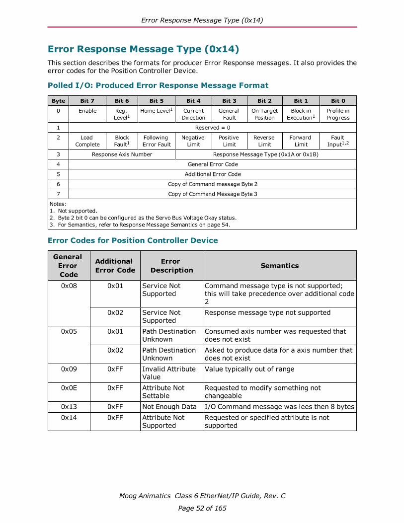
Error Response Message Type (0x14)
Moog Animatics Class 6 EtherNet/IP Guide, Rev. C
Page 52 of 165
Error Response Message Type (0x14)This section describes the formats for producer Error Response messages. It also provides the error codes for the Position Controller Device.
Polled I/O: Produced Error Response Message Format
Byte Bit 7 Bit 6 Bit 5 Bit 4 Bit 3 Bit 2 Bit 1 Bit 0
0 Enable Reg. Level1
Home Level1 CurrentDirection
General Fault
On Target Position
Block inExecution1
Profile inProgress
1 Reserved = 0
2 Load Complete
BlockFault1
Following Error Fault
Negative Limit
Positive Limit
Reverse Limit
Forward Limit
Fault Input1,2
3 Response Axis Number Response Message Type (0x1A or 0x1B)
4 General Error Code
5 Additional Error Code
6 Copy of Command message Byte 2
7 Copy of Command Message Byte 3
Notes:1. Not supported.2. Byte 2 bit 0 can be configured as the Servo Bus Voltage Okay status.3. For Semantics, refer to Response Message Semantics on page 54.
Error Codes for Position Controller Device
General Error Code
Additional Error Code
Error Description Semantics
0x08 0x01 Service Not Supported
Command message type is not supported; this will take precedence over additional code 2
0x02 Service Not Supported
Response message type not supported
0x05 0x01 Path Destination Unknown
Consumed axis number was requested that does not exist
0x02 Path Destination Unknown
Asked to produce data for a axis number that does not exist
0x09 0xFF Invalid Attribute Value
Value typically out of range
0x0E 0xFF Attribute Not Settable
Requested to modify something not changeable
0x13 0xFF Not Enough Data I/O Command message was lees then 8 bytes0x14 0xFF Attribute Not
SupportedRequested or specified attribute is not supported

Semantics for Command and Response Messages
Moog Animatics Class 6 EtherNet/IP Guide, Rev. C
Page 53 of 165
Semantics for Command and Response MessagesThis section provides semantic information for the command and response messages in the previous tables.
Command Message Semantics
This following table provides semantic information for the command messages.
ItemCmdMsgType
Description
Load Data/ Start Profile
Set from zero to one to load command data. The transition of this bit from zero to one will also start a Profile Move when the command message type contained in the command message field is the message type that starts a Profile Move for the mode selected.
Start Block Not supported.Incremental This bit is used to define the position value as either absolute or
incremental. 0 = absolute position value and 1 = incremental position value.
Direction (V. Mode)
This bit is used to control the direction of the motor in Velocity mode. 1 = forward, positive; 0 = reverse, negative.
Smooth Stop This bit is used to bring the motor to a controlled stop at the currently implemented deceleration rate.
Hard Stop This bit is used to bring the motor to an immediate stop.Registration Arm Not supported.Enable This bit is used to control the enable output. Clearing this bit will
set the enable output inactive and the currently executing motion profile will be aborted.
Block # This byte defines the block number to be executed when the Start Block bit transitions from zero to one.
Command Message Type
This field defines the Command Message Type
Response Message Type
This field defines the Response Message Type
Command Axis Number
These three bits define the Consumed Axis Connection attribute of the Position Controller Supervisor class. This attribute value specifies the instance number of all of the axis objects whose data are contained in the I/O command message. The SmartMotor is a single-axis device. Therefore, only axis 1 is used, which can be specified by either 0 or 1.
Target Position 0x01 This double word defines the Profile Move’s Target Position in position units, when the Load Data /Start Profile bit transitions from zero to one.
Target Velocity 0x02 This double word defines the Profile Move’s Target Velocity in profile units, when the Load Data /Start Profile bit transitions from zero to one

Response Message Semantics
Moog Animatics Class 6 EtherNet/IP Guide, Rev. C
Page 54 of 165
ItemCmdMsgType
Description
Acceleration 0x03 This double word defines the Profile Move’s Acceleration in profile units, when the Load Data /Start Profile bit transitions from zero to one.
Deceleration 0x04 This double word defines the Profile Move’s Target Position in profile units, when the Load Data /Start Profile bit transitions from zero to one.
Torque 0x05 This double word is used to set the output torque, when the Load Data /Start Profile bit transitions from zero to one. The torque value will only take effect when in torque mode. (Position Controller Object Attribute 3 = 2)
Attribute Value 0x1A–0x1B
This double word defines the value of the attribute to set, when the Load Data/Start Profile bit transitions from zero to one.
Object Attribute to Get
0x1A–0x1B
This byte defines the object attribute to get the value of and return in the response message.
Object Attribute to Set
0x1A–0x1B
This byte defines the object attribute to set to the new value defined by the Attribute Value when the Load Data/Start Profile bit transitions from zero to one.
Response Message Semantics
This following table provides semantic information for the response messages.
Item DescriptionProfile in Progress
This bit indicates that a profile move is in progress.
Block in Execution
Not supported.
On Target Position
This bit indicates whether or not the motor is on the last targeted position. (1 = Current position equals the last target position.)
General Fault This bit indicates the logical "or" of all fault conditions.Current Direction This bit shows the current direction of the motor. If the motor is not
moving the bit indicates the direction of the last commanded move. 0 = reverse, negative direction; 1 = forward, positive direction.
Home Level Not supported.Registration Level Not supported.Enable This bit indicates the state of the enable output. A 1 indicates the enable
output is active.Executing Block # This byte defines the currently executing block if the Block In Execution
bit is active.Fault Input Not supported.Forward Limit This bit indicates that the forward input is active.Reverse Limit This bit indicates that the reverse input is active.

Response Message Semantics
Moog Animatics Class 6 EtherNet/IP Guide, Rev. C
Page 55 of 165
Item DescriptionPositive Limit This bit indicates that the motor has attempted to travel past the
programmed positive limit position. This bit remains valid until the motor is moved within the limits or the programmed limit value is set greater than the current position.
Negative Limit This bit indicates that the motor has attempted to travel past the programmed negative limit position. This bit remains valid until the motor is moved within the limits or the programmed limit value is set less than the current position.
Following Error Fault
This bit indicates that a following error fault has occurred. This fault occurs when the following error, or difference between the commanded and actual position, exceeds the programmed allowable following error.
Block Fault Not supported.Load Complete This bit indicates that the command data contained in the command
message has been successfully loaded into the device.Response Message Type
This byte defines the Response Message Type
Response Axis Number
These three bits report the Produced Axis Connection attribute of the Position Controller Supervisor class. This attribute value specifies the instance number of all of the axis objects whose data is contained in the I/O response message. The SmartMotor is a single-axis device. Therefore, only axis 1 is used, which can be reported as either 0 or 1.
Actual Position This double word reflects the actual position in position units. If position feedback is not used, this word will report the commanded position.
Commanded Position
This double word reflects the commanded or calculated position in position units.
Actual Velocity This double word reflects the actual velocity in profile units.Command Velocity
This double word reflects the commanded or calculated velocity in profile units.
Torque This double word reflects the torque.Home Position This double word reflects the captured home position in position units.Index Position This double word reflects the captured index position in position units.Registration Position
This double word reflects the captured registration position in position units.
General Error Code
This byte identifies an error has been encountered. The specific behavior for the Position Controller Profile is summarized in Error Response Message Type (0x14) on page 52. For a complete list of General Error codes, see Appendix B in THE CIP NETWORKS LIBRARY Volume 1 - Common Industrial Protocol (CIP™), which is available on the ODVA.org website.
Additional Code This byte contains an object/service-specific value that further describes the error condition. If the responding object has no additional information to specify, then the value 0xFF is placed within this field.
Attribute Value This double word reflects the value of the attribute to get.Object Attribute to Get
This byte defines the object attribute from which to get the value.
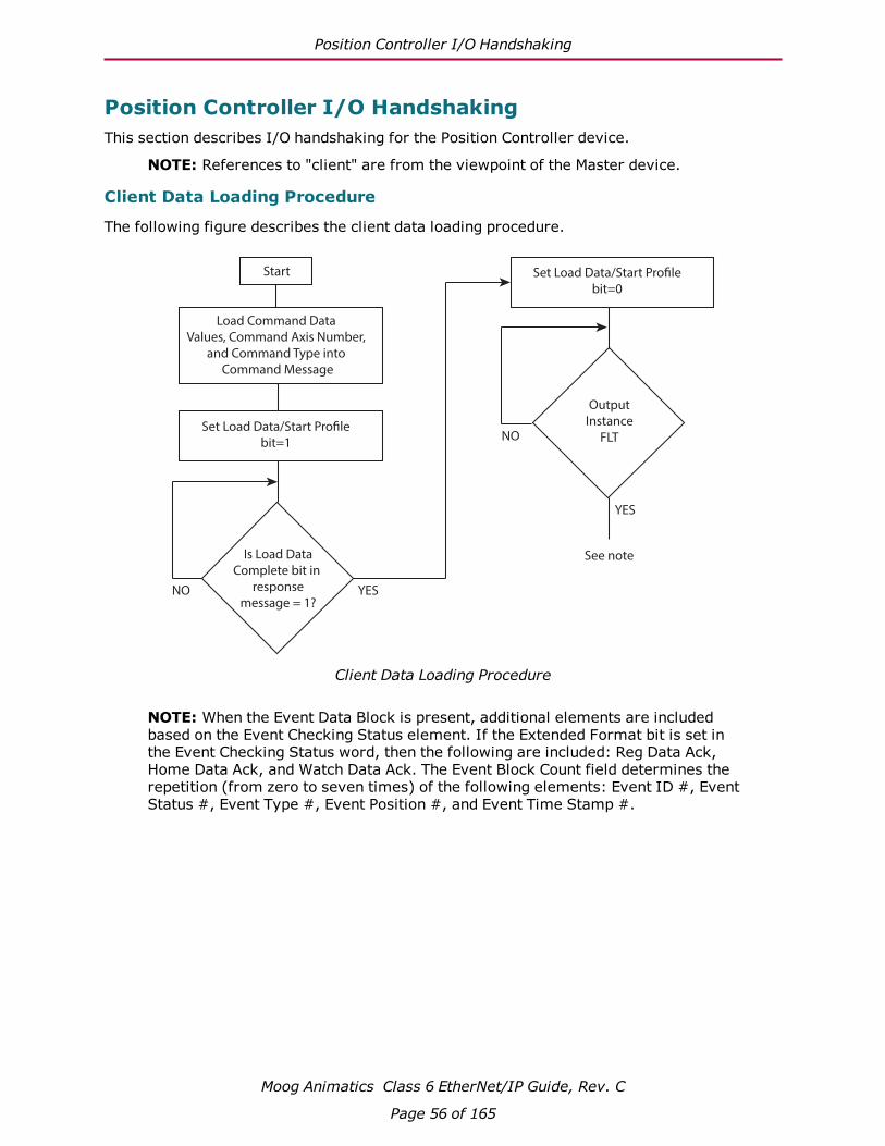
Position Controller I/O Handshaking
Moog Animatics Class 6 EtherNet/IP Guide, Rev. C
Page 56 of 165
Position Controller I/O HandshakingThis section describes I/O handshaking for the Position Controller device.
NOTE: References to "client" are from the viewpoint of the Master device.
Client Data Loading Procedure
The following figure describes the client data loading procedure.
Start
Load Command Data
Values, Command Axis Number,
and Command Type into
Command Message
Set Load Data/Start Pro!le
bit=1
Is Load Data
Complete bit in
response
message = 1?
Set Load Data/Start Pro!le
bit=0
Output
Instance
FLT
NO YES
NO
YES
See note
Client Data Loading Procedure
NOTE: When the Event Data Block is present, additional elements are included based on the Event Checking Status element. If the Extended Format bit is set in the Event Checking Status word, then the following are included: Reg Data Ack, Home Data Ack, and Watch Data Ack. The Event Block Count field determines the repetition (from zero to seven times) of the following elements: Event ID #, Event Status #, Event Type #, Event Position #, and Event Time Stamp #.
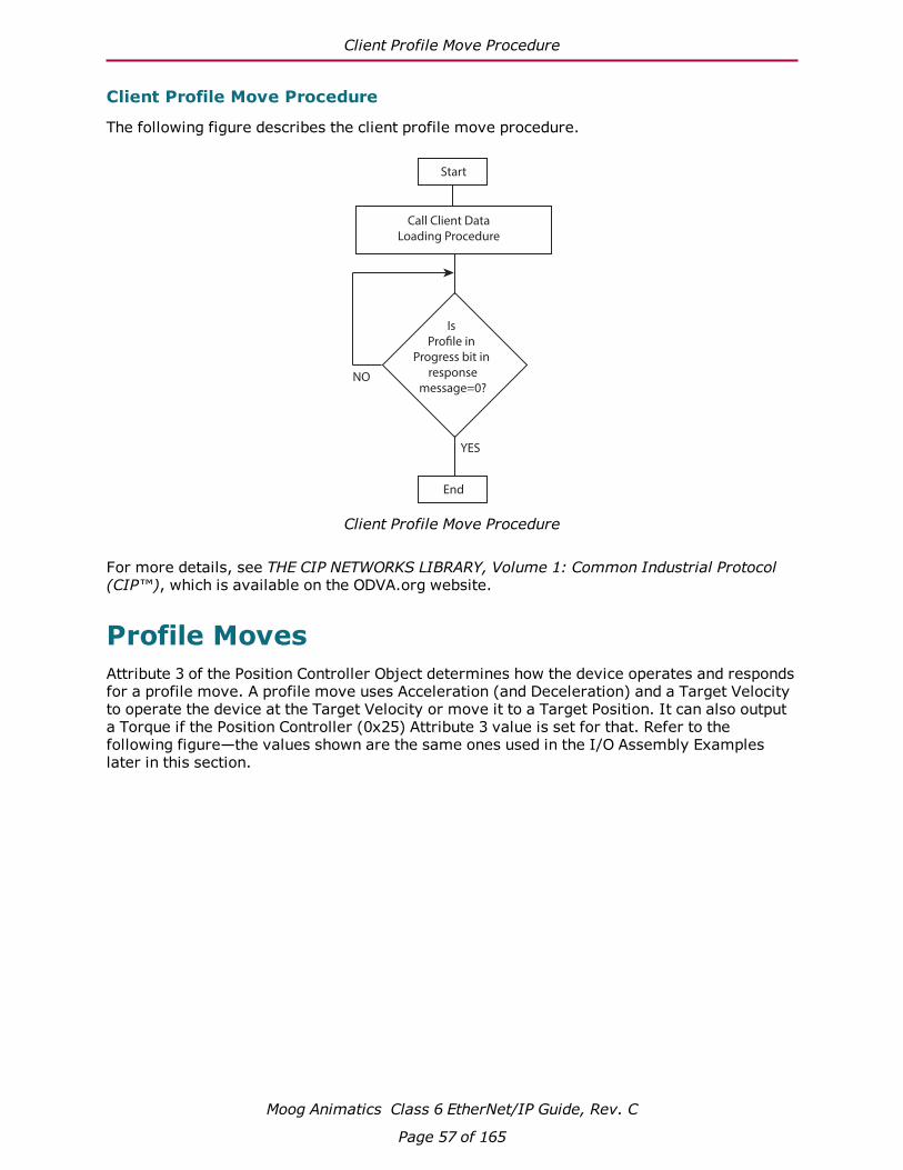
Client Profile Move Procedure
Moog Animatics Class 6 EtherNet/IP Guide, Rev. C
Page 57 of 165
Client Profile Move Procedure
The following figure describes the client profile move procedure.
Start
Call Client Data
Loading Procedure
Is
Pro!le in
Progress bit in
response
message=0?NO
YES
End
Client Profile Move Procedure
For more details, see THE CIP NETWORKS LIBRARY, Volume 1: Common Industrial Protocol (CIP™), which is available on the ODVA.org website.
Profile MovesAttribute 3 of the Position Controller Object determines how the device operates and responds for a profile move. A profile move uses Acceleration (and Deceleration) and a Target Velocity to operate the device at the Target Velocity or move it to a Target Position. It can also output a Torque if the Position Controller (0x25) Attribute 3 value is set for that. Refer to the following figure—the values shown are the same ones used in the I/O Assembly Examples later in this section.

Torque Command
Moog Animatics Class 6 EtherNet/IP Guide, Rev. C
Page 58 of 165
Acc
eler
atio
nAT
=10
0
Target Velocity
VT=32768
Deceleration*
Begin
Motion
Target Position
ReachedPosition=0 Position=8000
*NOTE: For the SmartMotor, there is an override that automatically sets
DT equal to AT if the motor power is turned on and only AT is set.
Motion Profile For I/O Assembly Examples
For more details, see THE CIP NETWORKS LIBRARY, Volume 1: Common Industrial Protocol (CIP™), which is available on the ODVA.org website.
Torque CommandAttribute 3 of the Position Controller Object determines how the device operates. The SmartMotor can output a Torque command to the integrated motor if the Position Controller (0x25) Attribute 3 value is set for Torque mode using a setting of 2 for the attribute.
Refer to the SmartMotor™ Developer's Guide for further information on Torque mode.
Control Mode Change - Change DynamicWith the SmartMotor, it is possible to change from one control mode to another during operation or while in a move profile in any other mode. In other words, while operating in Position mode with Position Controller mode Attribute 3 set to the value 0 and using Implicit Message Type 1, the programmer can change to Torque mode by setting Attribute 3 to the value 2 and then executing a new "Start Profile" with Implicit Message Type 5.
This "Change Dynamic" feature can be fully executed using the Implicit Messages of the Position Controller Device. This is facilitated using Message Type 0x1B during a profile once it has started, and then starting another profile after changing the mode attribute.
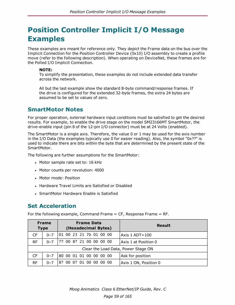
Position Controller Implicit I/O Message Examples
Moog Animatics Class 6 EtherNet/IP Guide, Rev. C
Page 59 of 165
Position Controller Implicit I/O Message ExamplesThese examples are meant for reference only. They depict the Frame data on the bus over the Implicit Connection for the Position Controller Device (0x10) I/O assembly to create a profile move (refer to the following description). When operating on DeviceNet, these frames are for the Polled I/O Implicit Connection.
NOTE: To simplify the presentation, these examples do not include extended data transfer across the network.
All but the last example show the standard 8-byte command/response frames. If the drive is configured for the extended 32-byte frames, the extra 24 bytes are assumed to be set to values of zero.
SmartMotor NotesFor proper operation, external hardware input conditions must be satisfied to get the desired results. For example, to enable the drive stage on the model SM23166MT SmartMotor, the drive-enable input (pin 8 of the 12-pin I/O connector) must be at 24 Volts (enabled).
The SmartMotor is a single axis. Therefore, the value 0 or 1 may be used for the axis number in the I/O Data (the examples typically use 0 for easier reading). Also, the symbol "0x??" is used to indicate there are bits within the byte that are determined by the present state of the SmartMotor.
The following are further assumptions for the SmartMotor:
l Motor sample rate set to: 16 kHz
l Motor counts per revolution: 4000
l Motor mode: Position
l Hardware Travel Limits are Satisfied or Disabled
l SmartMotor Hardware Enable is Satisfied
Set AccelerationFor the following example, Command Frame = CF, Response Frame = RF.
Frame Type
Frame Data (Hexadecimal Bytes) Result
CF 0–7 01 00 23 21 7D 01 00 00 Axis 1 ADT=100
RF 0–7 ?? 00 8? 21 00 00 00 00 Axis 1 at Position 0
Clear the Load Data, Power Stage ON
CF 0–7 80 00 01 01 00 00 00 00 Ask for position
RF 0–7 8? 00 0? 01 00 00 00 00 Axis 1 ON, Position 0

Set Velocity, Leave Drive ON
Moog Animatics Class 6 EtherNet/IP Guide, Rev. C
Page 60 of 165
Set Velocity, Leave Drive ONFor the following example, Command Frame = CF, Response Frame = RF.
Frame Type
Frame Data (Hexadecimal Bytes) Result
CF 0–7 8D 00 02 01 A0 0F 00 00 Axis 1 VT=32768
RF 0–7 8? 00 8? 01 00 00 00 00 Axis 1 at Position 0
Clear the Load Data
CF 0–7 80 00 01 01 00 00 00 00 Ask for position
RF 0–7 8? 00 0? 01 00 00 00 00 Axis 1 ON, Position 0
Set Target Position, Perform MoveFor the following example, Command Frame = CF, Response Frame = RF.
Frame Type
Frame Data (Hexadecimal Bytes) Result
CF 0–7 81 00 01 01 40 1F 00 00 PT=8000 G
RF 0–7 81 00 8? 01 00 00 00 00 Axis 1 at Position 0
Clear the Load Data (assumes motor completed move)
CF 0–7 80 00 01 01 00 00 00 00 Ask for position
RF 0–7 80 00 0? 01 40 1F 00 00 Position 8000
Disable Hardware Limits (Object 0x25, Attribute 49)For the following example, Command Frame = CF, Response Frame = RF.
Frame Type
Frame Data (Hexadecimal Bytes) Result
CF 0–7 01 31 1B 31 E0 00 00 00
RF 0–7 0? 31 8? 1B E0 00 00 00
Clear the Load Data
CF 0–7 00 00 01 01 00 00 00 00 Ask for position
RF 0–7 0? 00 0? 01 00 00 00 00 At Position 0
NOTE: If the SmartMotor is on, this will turn it off.

Extended Position Move (32-byte frame)
Moog Animatics Class 6 EtherNet/IP Guide, Rev. C
Page 61 of 165
Extended Position Move (32-byte frame)For the following example, Command Frame = CF, Response Frame = RF.
Frame Type
Frame Data (Hexadecimal Bytes) Result
CF 0–1516–31
8d 00 06 01 00 00 00 00 60 e3 16 00 90 e2 00 00
ac 0d 00 00 10 0e 00 00 00 00 00 00 00 00 00 00
AT=3500 DT=3600 VT=58000 PRT=1500000 G
RF 0–1516–31
91 00 80 01 00 00 00 00 00 00 00 00 00 00 00 00
00 00 00 00 00 00 00 00 00 00 00 00 00 00 00 00
Axis 1 at Position 0, Velocity 0Load Complete set
RF 0–1516–31
91 00 00 01 01 00 00 00 01 00 00 00 7f 00 00 00
00 00 00 00 00 00 00 00 00 00 00 00 00 00 00 00
Axis 1 at Position 1, Velocity 127Load Complete clear
The move continues until the target position is reached
RF 0–1516–31
94 00 00 01 60 e3 16 00 60 e3 16 00 00 00 00 00
00 00 00 00 00 00 00 00 00 00 00 00 00 00 00 00
Axis 1 at Position 1500000, Velocity 0Load Complete clear

Object Reference
Object ReferenceThis chapter provides details on the EtherNet/IP protocol objects used with the Moog Animatics SmartMotor. The following TOC provides a listing of those objects.
The Moog Animatics Class 6 SmartMotor device profile supports the required object classes of the Position Controller Device 0x10 (see Volume 1 of the ODVA CIP specification). For more details, see THE CIP NETWORKS LIBRARY, Volume 1: Common Industrial Protocol (CIP™), which is available on the ODVA.org website.
Required Objects 64
Identity Object (0x01) 65
Class Attributes 65
Identity Attributes 65
Services 68
Message Router Object (0x02) 69
Class Attributes 69
Instance Attributes 69
Services 69
Assembly Object (0x04) 70
Class Attributes 70
Instance Attributes 70
Services 70
Connection Manager Object (0x06) 71
Class Attributes 71
Instance Attributes 71
Services 71
TCP/IP Interface Object (0xF5) 72
Class Attributes 72
Instance Attributes 72
Services 78
Ethernet Link Object (0xF6) 79
Class Attributes 79
Instance Attributes 79
Services 84
Application Objects 85
Position Controller Supervisor (0x24) 86
Moog Animatics Class 6 EtherNet/IP Guide, Rev. C
Page 62 of 165

Object Reference
Class Attributes 86
Object Instance 1 Attributes 87
Services 87
Position Controller (0x25) 88
Class Attributes 88
Instance Attributes 88
Services 92
Error Responses 92
Additional Objects 93
Device Level Ring (DLR) Object (0x47) 94
Class Attributes 94
Instance Attributes 94
Services 95
QoS Object (0x48) 96
Class Attributes 96
Instance Attributes 96
Services 97
SmartMotor I/O Object (0x71) 98
Attribute Table (Instance 0) 98
Attribute Table (One instance per I/O pin) 98
SmartMotor User Variable Object (0x72) 99
Class Attribute (Instance 0) 99
Instance Attributes (Instance 1-7) 100
Semantics 100
Error Responses 100
Instance Descriptions 101
Examples 102
Moog Animatics Class 6 EtherNet/IP Guide, Rev. C
Page 63 of 165

Required Objects
Required ObjectsThe following sections/tables list the attributes for each of the CIP required and network objects.
Identity Object (0x01) 65
Class Attributes 65
Identity Attributes 65
Services 68
Message Router Object (0x02) 69
Class Attributes 69
Instance Attributes 69
Services 69
Assembly Object (0x04) 70
Class Attributes 70
Instance Attributes 70
Services 70
Connection Manager Object (0x06) 71
Class Attributes 71
Instance Attributes 71
Services 71
TCP/IP Interface Object (0xF5) 72
Class Attributes 72
Instance Attributes 72
Services 78
Ethernet Link Object (0xF6) 79
Class Attributes 79
Instance Attributes 79
Services 84
Moog Animatics Class 6 EtherNet/IP Guide, Rev. C
Page 64 of 165
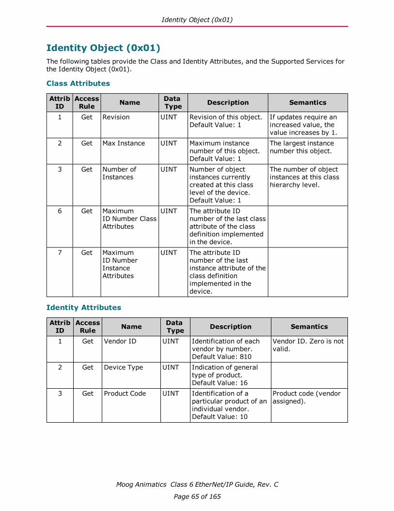
Identity Object (0x01)
Moog Animatics Class 6 EtherNet/IP Guide, Rev. C
Page 65 of 165
Identity Object (0x01)The following tables provide the Class and Identity Attributes, and the Supported Services for the Identity Object (0x01).
Class Attributes
AttribID
AccessRule Name Data
Type Description Semantics
1 Get Revision UINT Revision of this object.Default Value: 1
If updates require an increased value, the value increases by 1.
2 Get Max Instance UINT Maximum instance number of this object.Default Value: 1
The largest instance number this object.
3 Get Number of Instances
UINT Number of object instances currently created at this class level of the device.Default Value: 1
The number of object instances at this class hierarchy level.
6 Get Maximum ID Number Class Attributes
UINT The attribute ID number of the last class attribute of the class definition implemented in the device.
7 Get Maximum ID Number Instance Attributes
UINT The attribute ID number of the last instance attribute of the class definition implemented in the device.
Identity Attributes
AttribID
AccessRule Name Data
Type Description Semantics
1 Get Vendor ID UINT Identification of each vendor by number.Default Value: 810
Vendor ID. Zero is not valid.
2 Get Device Type UINT Indication of general type of product.Default Value: 16
3 Get Product Code UINT Identification of a particular product of an individual vendor.Default Value: 10
Product code (vendor assigned).

Identity Attributes
Moog Animatics Class 6 EtherNet/IP Guide, Rev. C
Page 66 of 165
AttribID
AccessRule Name Data
Type Description Semantics
4 Get Revision STRUCTof:
Revision of the item the Identity Object represents.Default Value: 1.1
Zero is not valid for either the Major or Minor Revision fields.
Major Revision USINT Incremented by the vendor when there is a significant change to the product "fit, form, or function".
Limited to values between 1 and 127; the eighth bit (representing, when set to one, values of 128 – 255) is reserved by CIP and shall have a value of zero.
Minor Revision USINT Identifies product changes that do not affect user configuration choices.
Displayed as three digits with leading zeros as necessary.
5 Get Status WORD Summary status of device.
See below: Attribute 5: Status
6 Get Serial Number UDINT Serial number of device Set by factory.7 Get Product Name SHORT_
STRINGHuman readable identification.
Set by factory; will match motor's name plate.
8 Get State USINT Present state of the device as represented by the state transition diagram.
0 = Nonexistent 1 = Device Self Testing 2 = Standby 3 = Operational 4 = Major Recoverable Fault 5 = Major Unrecoverable Fault 6 – 254 = Reserved 255 = Default Value
9 Get Configuration Consistency Value
UINT Contents identify configuration of device.
10 Get Heartbeat Interval
USINT The nominal interval between heartbeat messages in seconds.

Identity Attributes
Moog Animatics Class 6 EtherNet/IP Guide, Rev. C
Page 67 of 165
Instance Attributes Semantics
Attribute 5: Status
Bits Name Description0 Owned TRUE indicates the device (or an object within the device)
has an owner. Within the Master/Slave paradigm the setting of this bit means that the Predefined Master/Slave Connection Set has been allocated to a master. Outside the Master/Slave paradigm the meaning of this bit is TBD.
1 Reserved; 0.2 Configured TRUE indicates the application of the device has been
configured to do something different than the “out–of–box” default. This shall not include configuration of the communications.
3 Reserved; 0.4-7 Extended Device Status Vendor–specific or as defined by the following table. The
EDS shall indicate if the device follows a vendor-specific definition for these bits by using the DeviceStatusAssembly keyword. See Default Values for Bits 4-7.
8 Minor Recoverable Fault TRUE indicates the device detected a problem with itself, which is thought to be recoverable. The problem does not cause the device to go into one of the faulted states.
9 Minor Unrecoverable Fault
TRUE indicates the device detected a problem with itself, which is thought to be unrecoverable. The problem does not cause the device to go into one of the faulted states.
10 Major Recoverable Fault TRUE indicates the device detected a problem with itself, which caused the device to go into the “Major Recoverable Fault” state.
11 Major Unrecoverable Fault
TRUE indicates the device detected a problem with itself, which caused the device to go into the “Major Unrecoverable Fault” state.
12-15 Extended Device Status 2
Reserved; eiter 0 or vendor specific.
Default Values for Bits 4-7
Value Description0 Self-Testing or Unknown1 Firmware Update in Progress2 At least one faulted I/O connection3 No I/O connections established4 Non-Volatile Configuration bad5 Major Fault – either bit 10 or bit 11 is true (1)6 At least one I/O connection in run mode7 At least one I/O connection established, all in idle mode
8-9 Reserved

Services
Moog Animatics Class 6 EtherNet/IP Guide, Rev. C
Page 68 of 165
Value Description10-15 Vendor specific1
1. No mechanism is provided to enumerate the vendor-specific use of these values in the EDS file.
Services
ServiceCode
Supported in:Name Description
Class Instance0x01 ● ● Get_Attributes_All Returns a predefined listing of this
object's attributes0x05 Reset Invokes the Reset service for the
device.0x0E ● ● Get_Attribute_Single Returns the contents of the specified
attribute0x10 ● ● Set_Attribute_Single Modifies an attribute (required if
Heartbeat Interval is defined)
For more details, see THE CIP NETWORKS LIBRARY, Volume 1: Common Industrial Protocol (CIP™), which is available on the ODVA.org website.

Message Router Object (0x02)
Moog Animatics Class 6 EtherNet/IP Guide, Rev. C
Page 69 of 165
Message Router Object (0x02)The following tables provide the Class and Identity Attributes, and the Supported Services for the Message Router Object (0x02).
Class Attributes
AttribID
AccessRule Name Data
Type Description Semantics
1 Get Revision UINT Revision of this object.Default Value: 1
The current assigned value is 1. If updates require an increased value, the value increases by 1.
2 Get Max Instance UINT Maximum instance number of this object.Default Value: 1
The largest instance number of a created object at this class hierarchy level.
3 Get Number of Instances
UINT Number of object instances currently created at this class level of the device.Default Value: 1
The number of object instances at this class hierarchy level.
6 Get Maximum ID Number Class Attributes
UINT The attribute ID number of the last class attribute of the class definition implemented in the device.
7 Get Maximum ID Number Instance Attributes
UINT The attribute ID number of the last instance attribute of the class definition implemented in the device.
Instance Attributes
AttribID
AccessRule Name Data
Type Description Semantics
Services
ServiceCode
Supported in:Name Description
Class Instance0x0E ● ● Get_Attribute_Single Returns the contents of the specified
attribute
For more details, see THE CIP NETWORKS LIBRARY, Volume 1: Common Industrial Protocol (CIP™), which is available on the ODVA.org website.

Assembly Object (0x04)
Moog Animatics Class 6 EtherNet/IP Guide, Rev. C
Page 70 of 165
Assembly Object (0x04)The following tables provide the Class and Identity Attributes, and the Supported Services for the Assembly Object (0x04).
Class Attributes
AttribID
AccessRule Name Data
Type Description Semantics
1 Get Revision UINT Revision of this object.Default Value: 2
The current value assigned to this attribute is 2.
2 Get Max Instance UINT Maximum instance number of this object.Default Value: 0xFFFF
The largest instance number of a created object at this class hierarchy level.
3 Get Number of Instances
UINT Number of object instances currently created at this class level of the device.Default Value: 0
The number of object instances at this class hierarchy level.
6 Get Maximum ID Number Class Attributes
UINT The attribute ID number of the last class attribute of the class definition implemented in the device.
7 Get Maximum ID Number Instance Attributes
UINT The attribute ID number of the last instance attribute of the class definition implemented in the device.
Instance Attributes
AttribID
AccessRule Name Data Type Description Semantics
3 Get Data ARRAY of BYTE Assembly Data 4 Get Size UINT Number of bytes in Attribute 3.
Services
ServiceCode
Supported in:Name Description
Class Instance0x0E ● ● Get_Attribute_Single Returns contents of the specified attribute0x10 ● Set_Attribute_Single Modifies an attribute value.
For more details, see THE CIP NETWORKS LIBRARY, Volume 1: Common Industrial Protocol (CIP™), which is available on the ODVA.org website.
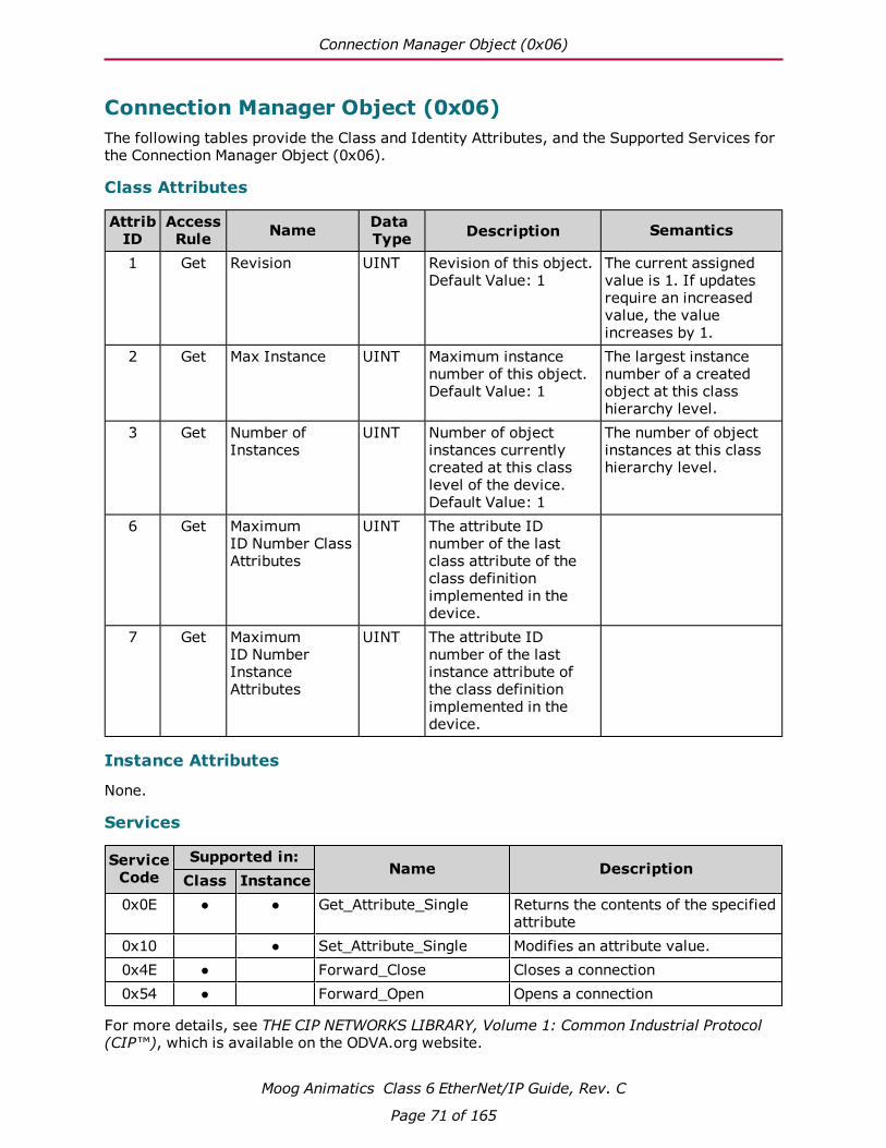
Connection Manager Object (0x06)
Moog Animatics Class 6 EtherNet/IP Guide, Rev. C
Page 71 of 165
Connection Manager Object (0x06)The following tables provide the Class and Identity Attributes, and the Supported Services for the Connection Manager Object (0x06).
Class Attributes
AttribID
AccessRule Name Data
Type Description Semantics
1 Get Revision UINT Revision of this object.Default Value: 1
The current assigned value is 1. If updates require an increased value, the value increases by 1.
2 Get Max Instance UINT Maximum instance number of this object.Default Value: 1
The largest instance number of a created object at this class hierarchy level.
3 Get Number of Instances
UINT Number of object instances currently created at this class level of the device.Default Value: 1
The number of object instances at this class hierarchy level.
6 Get Maximum ID Number Class Attributes
UINT The attribute ID number of the last class attribute of the class definition implemented in the device.
7 Get Maximum ID Number Instance Attributes
UINT The attribute ID number of the last instance attribute of the class definition implemented in the device.
Instance Attributes
None.
Services
ServiceCode
Supported in:Name Description
Class Instance0x0E ● ● Get_Attribute_Single Returns the contents of the specified
attribute0x10 ● Set_Attribute_Single Modifies an attribute value.0x4E ● Forward_Close Closes a connection0x54 ● Forward_Open Opens a connection
For more details, see THE CIP NETWORKS LIBRARY, Volume 1: Common Industrial Protocol (CIP™), which is available on the ODVA.org website.

TCP/IP Interface Object (0xF5)
Moog Animatics Class 6 EtherNet/IP Guide, Rev. C
Page 72 of 165
TCP/IP Interface Object (0xF5)The following tables provide the Class and Identity Attributes, and the Supported Services for the TCP/IP Interface Object (0xF5).
Class Attributes
AttribID
AccessRule Name Data
Type Description Semantics
1 Get Revision UINT Revision of this object.Default Value: 3
2 Get Max Instance UINT Maximum instance number of this object.Default Value: 1
The largest instance number of a created object at this class hierarchy level.
3 Get Number of Instances
UINT Number of object instances currently created at this class level of the device.Default Value: 1
The number of object instances at this class hierarchy level.
6 Get Maximum ID Number Class Attributes
UINT The attribute ID number of the last class attribute of the class definition implemented in the device.
7 Get Maximum ID Number Instance Attributes
UINT The attribute ID number of the last instance attribute of the class definition implemented in the device.
Instance Attributes
AttribID
AccessRule Name Data
Type Description Semantics
1 Get Status DWORD Interface status See below: Attribute 1: Status
2 Get Configuration Capability
DWORD Interface capability flags.Default Value: 0x95
Bitmap of capability flags. See below: Attribute 2: Configuration Capability
3 Set/Get(NV)
Configuration Control
DWORD Interface control flagsDefault Value: 0
Bitmap of control flags. See below: Attribute 3: Configuration Control

Instance Attributes
Moog Animatics Class 6 EtherNet/IP Guide, Rev. C
Page 73 of 165
AttribID
AccessRule Name Data
Type Description Semantics
4 Get Physical Link Object
STRUCT of:
Path to physical link object.
E.g., 0x20, 0xF6, 0x24, 0x01; where:[20] = 8 bit class segment type; [F6] = Ethernet Link Object class; [24] = 8 bit instance segment type; [01] = instance 1
Path size UINT Size of Path Number of 16 bit words in Path
Path Padded EPATH
Logical segments identifying the physical link object.
Path is restricted to one logical class segment and one logical instance segment. Max size is 12 bytes.

Instance Attributes
Moog Animatics Class 6 EtherNet/IP Guide, Rev. C
Page 74 of 165
AttribID
AccessRule Name Data
Type Description Semantics
5(a) Set/Get(NV)
Interface Configuration
STRUCT of:
TCP/IP network interface configuration.Default Value: 0
Contains the configuration parameters required for a device to operate as a TCP/IP node.
IP Address(a) UDINT 0 = no IP address has been configured. Otherwise, set IP address to valid Class A, B, or C address. Loopback address (127.0.0.1) is not allowed.
Network Mask UDINT The device’s network mask
0 = network mask address not configured
Gateway Address
UDINT Default gateway address
0 = no gateway address has been configured. Otherwise, set address to valid Class A, B, or C address. Loopback address (127.0.0.1) is not allowed.
Name Server UDINT Primary name server 0 = no name server address has been configured. Otherwise, set address to valid Class A, B, or C address.
Name Server 2 UDINT Secondary name server 0 = no secondary name server address has been configured. Otherwise, set address to valid Class A, B, or C address.
Domain Name STRING Default domain name ASCII characters. Maximum length is 48 characters.0 = no Domain Name is configured.
6 Set/Get(NV)
Host Name STRING Host name.Default Value: ""
ASCII characters. Maximum length is 64 characters. Pad to an even number of characters (pad not included in length).0 = no Host Name is configured.
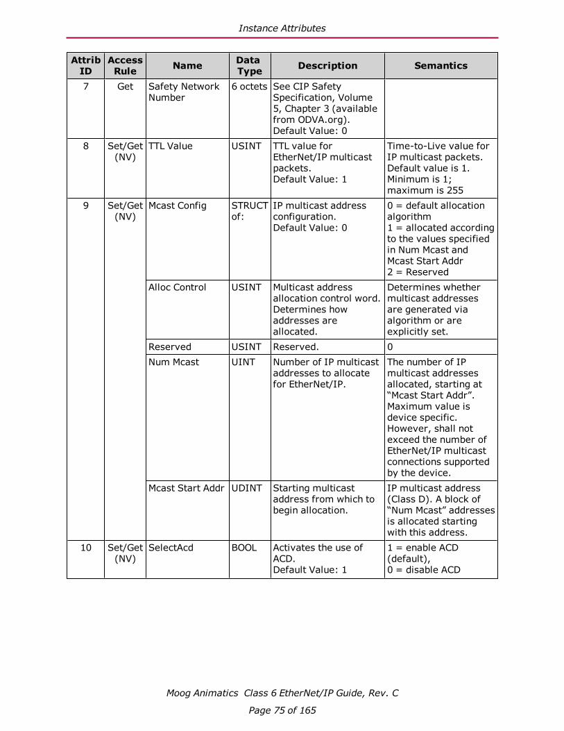
Instance Attributes
Moog Animatics Class 6 EtherNet/IP Guide, Rev. C
Page 75 of 165
AttribID
AccessRule Name Data
Type Description Semantics
7 Get Safety Network Number
6 octets See CIP Safety Specification, Volume 5, Chapter 3 (available from ODVA.org).Default Value: 0
8 Set/Get(NV)
TTL Value USINT TTL value for EtherNet/IP multicast packets.Default Value: 1
Time-to-Live value for IP multicast packets. Default value is 1. Minimum is 1; maximum is 255
9 Set/Get(NV)
Mcast Config STRUCT of:
IP multicast address configuration.Default Value: 0
0 = default allocation algorithm1 = allocated according to the values specified in Num Mcast and Mcast Start Addr2 = Reserved
Alloc Control USINT Multicast address allocation control word. Determines how addresses are allocated.
Determines whether multicast addresses are generated via algorithm or are explicitly set.
Reserved USINT Reserved. 0Num Mcast UINT Number of IP multicast
addresses to allocate for EtherNet/IP.
The number of IP multicast addresses allocated, starting at “Mcast Start Addr”. Maximum value is device specific. However, shall not exceed the number of EtherNet/IP multicast connections supported by the device.
Mcast Start Addr UDINT Starting multicast address from which to begin allocation.
IP multicast address (Class D). A block of “Num Mcast” addresses is allocated starting with this address.
10 Set/Get(NV)
SelectAcd BOOL Activates the use of ACD.Default Value: 1
1 = enable ACD (default), 0 = disable ACD

Instance Attributes
Moog Animatics Class 6 EtherNet/IP Guide, Rev. C
Page 76 of 165
AttribID
AccessRule Name Data
Type Description Semantics
11 Set/Get(NV)
Last Conflict Detected
STRUCT of:
Structure containing information related to the last conflict detected.Default Value: 0
ACD Diagnostic Parameters.See below: Attribute 11: LastConflictDetected
AcdActivity USINT State of ACD activity when last conflict detected.Default Value: 0
ACD activity
RemoteMAC Array of 6 USINT
MAC address of remote node from the ARP PDU in which a conflict was detected.Default Value: 0
MAC from Eth Pkt Hdr.
ArpPdu ARRAY of 28 USINT
Copy of the raw ARP PDU in which a conflict was detected.Default Value: 0
ARP PDU
12 Set/Get(NV)
EtherNet/IP QuickConnect
BOOL Enable/Disable of QuickConnect feature.Default Value: 0
0 = Disable (default)1 = Enable
13 Set/Get(NV)
Encapsulation Inactivity Timeout
UINT Number of seconds of inactivity before TCP connection is closed.Default Value: 120
0 = disabled1-3600 = timeout (sec)
a. The drive is shipped out-of-box with an IP Address of 0.0.0.0. This address enables DHCP support for addressing. The DHCP server manages the IP Address assigned to the drive. If a value other than 0.0.0.0 is assigned then DHCP is disabled and the static IP Address is used. Assigning an IP Address of 0.0.0.0 will re-enable DHCP. Value is formatted as an IP address entered as a string, e.g., IPCTL(0,"192.168.0.10"). By default, these values are set to 0 (i.e., "0.0.0.0")
NOTE: The drive must be power cycled or reset using a "Z" terminal window command before the new IP Address takes affect.
Instance Attributes Semantics
Attribute 1: Status
Bits Name Description0-3 Interface
Configuration Status
0 = Interface Configuration attribute has not been configured. 1 = Interface Configuration attribute contains configuration obtained from BOOTP, DHCP or nonvolatile storage. 2 = IP address member of the Interface Configuration attribute contains configuration, obtained from hardware settings (e.g.: pushwheel, thumbwheel, etc.) 3-15 = Reserved
4 Mcast Pending Indicates a pending configuration change in the TTL Value and/or Mcast Config attributes. This bit is set when either the TTL Value or Mcast Config attribute is set; it is cleared the next time the device starts.

Instance Attributes
Moog Animatics Class 6 EtherNet/IP Guide, Rev. C
Page 77 of 165
Bits Name Description5 Interface
Configuration Pending
Indicates a pending configuration change in the Interface Configuration attribute. This bit is 1 (TRUE) when Interface Configuration attribute are set and the device requires a reset in order for the configuration change to take effect (as indicated in the Configuration Capability attribute). The intent of the Interface Config Pending bit is to allow client software to detect that a device’s IP configuration has changed, but will not take effect until the device is reset.
6 AcdStatus Indicates when an IP address conflict has been detected by ACD. This bit shall default to 0 (FALSE) on startup. If ACD is supported and enabled, then this bit is set to 1 (TRUE) any time an address conflict is detected as defined by the [ConflictDetected] transitions.
7 AcdFault Indicates when an IP address conflict has been detected by ACD or the defense failed, and that the current Interface Configuration cannot be used due to this conflict. This bit is 1 (TRUE) if an address conflict has been detected and this interface is currently in the Notification & FaultAction or AcquireNewIpv4Parameters ACD state, and is 0 (FALSE) otherwise.When this bit is set, then this CIP port will not be usable. However, for devices with multiple ports, this bit provides a way of determining if the port has an ACD fault and thus cannot be used.
8-31 Reserved 0
Attribute 2: Configuration Capability
Bits Name Description0 BOOTP Client 1 (TRUE) = device is capable of obtaining its network
configuration via BOOTP.1 DNS Client 1 (TRUE) = device is capable of resolving host names by querying
a DNS server.2 DHCP Client 1 (TRUE) = device is capable of obtaining its network
configuration via DHCP.3 DHCP-DNS
Update0
4 Configuration Settable
1 (TRUE) = the Interface Configuration attribute is settable.
5 Hardware Configurable
If 1 (TRUE), the IP Address member of the Interface Configuration attribute can be obtained from hardware settings. If this bit is FALSE the Status Instance Attribute (1), Interface Configuration Status field value shall never be 2. (The Interface Configuration attribute contains valid configuration, obtained from hardware settings.)
6 Interface Configuration Change Requires Reset
If 1 (TRUE), the device requires a restart in order for a change to the Interface Configuration attribute to take effect. If this bit is FALSE a change in the Interface Configuration attribute will take effect immediately.
7 AcdCapable 1 (TRUE) = device is ACD capable8-31 Reserved 0
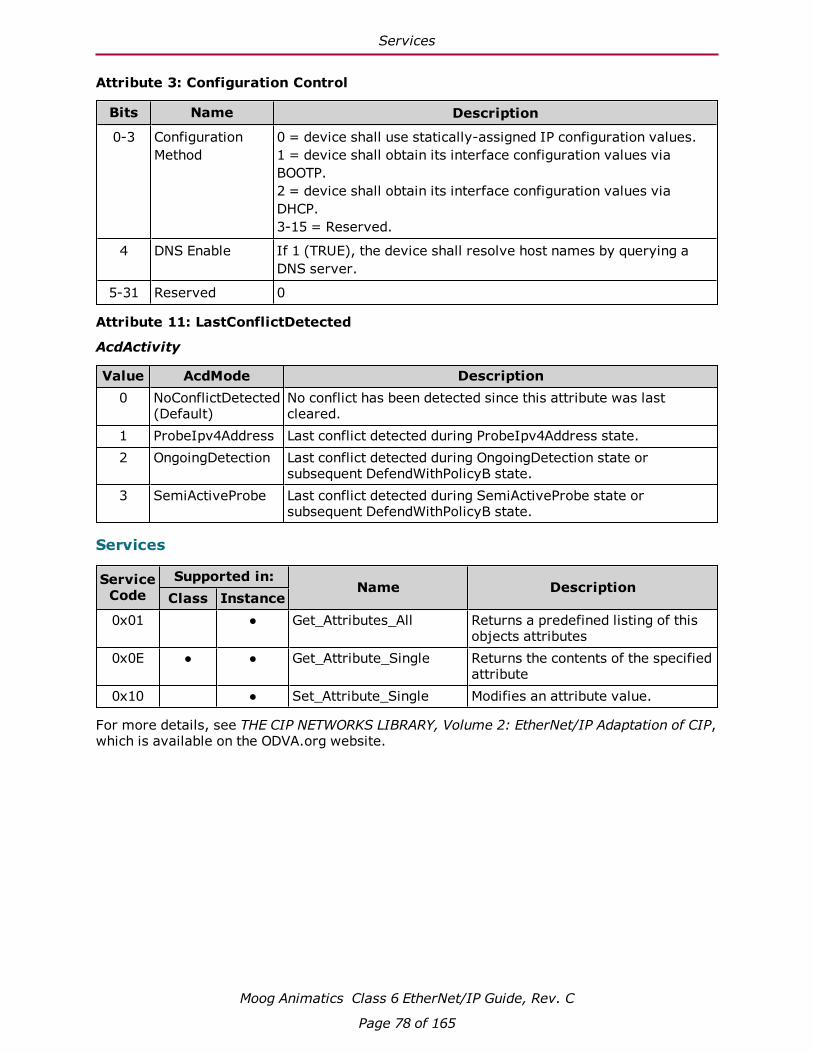
Services
Moog Animatics Class 6 EtherNet/IP Guide, Rev. C
Page 78 of 165
Attribute 3: Configuration Control
Bits Name Description
0-3 Configuration Method
0 = device shall use statically-assigned IP configuration values. 1 = device shall obtain its interface configuration values via BOOTP. 2 = device shall obtain its interface configuration values via DHCP. 3-15 = Reserved.
4 DNS Enable If 1 (TRUE), the device shall resolve host names by querying a DNS server.
5-31 Reserved 0
Attribute 11: LastConflictDetected
AcdActivity
Value AcdMode Description0 NoConflictDetected
(Default)No conflict has been detected since this attribute was last cleared.
1 ProbeIpv4Address Last conflict detected during ProbeIpv4Address state.2 OngoingDetection Last conflict detected during OngoingDetection state or
subsequent DefendWithPolicyB state.3 SemiActiveProbe Last conflict detected during SemiActiveProbe state or
subsequent DefendWithPolicyB state.
Services
ServiceCode
Supported in:Name Description
Class Instance0x01 ● Get_Attributes_All Returns a predefined listing of this
objects attributes0x0E ● ● Get_Attribute_Single Returns the contents of the specified
attribute0x10 ● Set_Attribute_Single Modifies an attribute value.
For more details, see THE CIP NETWORKS LIBRARY, Volume 2: EtherNet/IP Adaptation of CIP, which is available on the ODVA.org website.

Ethernet Link Object (0xF6)
Moog Animatics Class 6 EtherNet/IP Guide, Rev. C
Page 79 of 165
Ethernet Link Object (0xF6)The following tables provide the Class and Identity Attributes, and the Supported Services for the Ethernet Link Object (0xF6).
Class Attributes
AttribID
AccessRule Name Data
Type Description Semantics
1 Get Revision UINT Revision of this object.Default Value: 3
The minimum value = 1. Use ≥2 if instance attribute 6 is imple-mented.Use 3 if any instance attributes 7-10 are implemented. Max value = 3.
2 Get Max Instance UINT Maximum instance number of this object.Default Value: 2
The largest instance number of a created object at this class hierarchy level.
3 Get Number of Instances
UINT Number of object instances currently created at this class level of the device.Default Value: 2
The number of object instances at this class hierarchy level.
6 Get Maximum ID Number Class Attributes
UINT The attribute ID number of the last class attribute of the class definition implemented in the device.
7 Get Maximum ID Number Instance Attributes
UINT The attribute ID number of the last instance attribute of the class definition implemented in the device.
Instance Attributes
AttribID
AccessRule Name Data
Type Description Semantics
1 Get Interface Speed UINT Interface speed currently in use.Default Value: 100
Speed in Mbps (e.g., 0, 10, 100, 1000, etc.)
2 Get Interface Flags DWORD Interface status flags.Default Value: 0x20
Bit map of interface flags. See Attribute 2: Interface Flags.
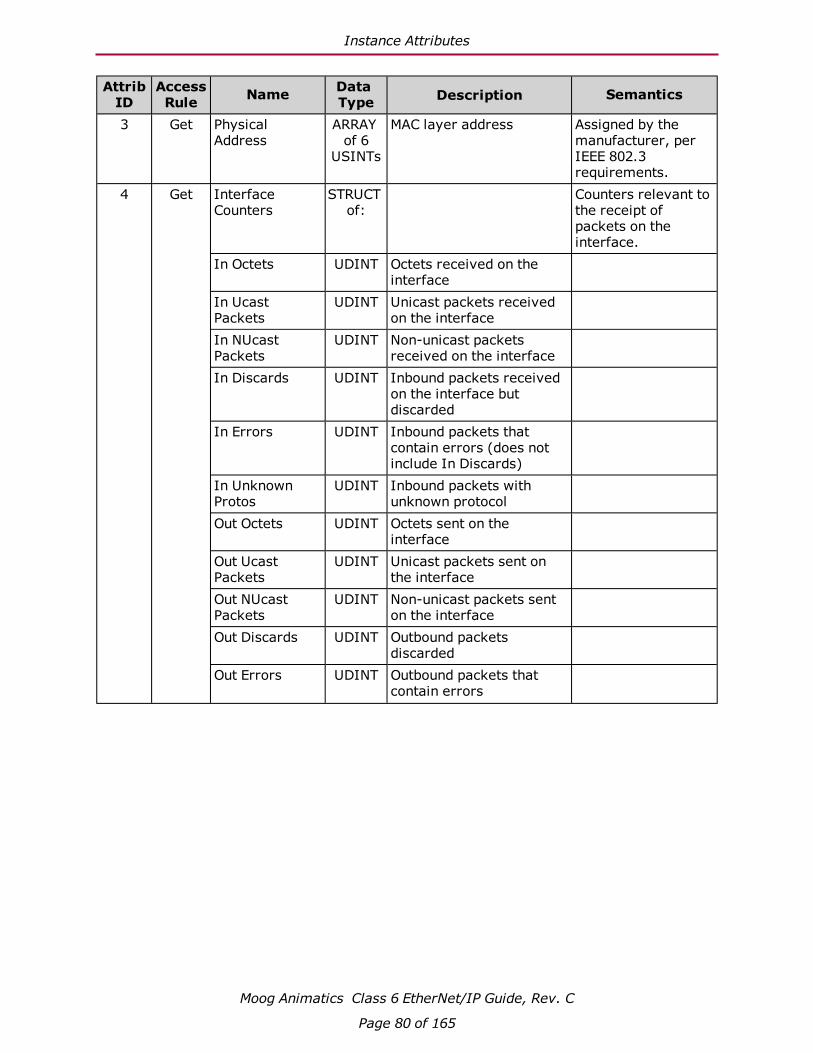
Instance Attributes
Moog Animatics Class 6 EtherNet/IP Guide, Rev. C
Page 80 of 165
AttribID
AccessRule Name Data
Type Description Semantics
3 Get Physical Address
ARRAY of 6
USINTs
MAC layer address Assigned by the manufacturer, per IEEE 802.3 requirements.
4 Get Interface Counters
STRUCT of:
Counters relevant to the receipt of packets on the interface.
In Octets UDINT Octets received on the interface
In Ucast Packets
UDINT Unicast packets received on the interface
In NUcast Packets
UDINT Non-unicast packets received on the interface
In Discards UDINT Inbound packets received on the interface but discarded
In Errors UDINT Inbound packets that contain errors (does not include In Discards)
In Unknown Protos
UDINT Inbound packets with unknown protocol
Out Octets UDINT Octets sent on the interface
Out Ucast Packets
UDINT Unicast packets sent on the interface
Out NUcast Packets
UDINT Non-unicast packets sent on the interface
Out Discards UDINT Outbound packets discarded
Out Errors UDINT Outbound packets that contain errors

Instance Attributes
Moog Animatics Class 6 EtherNet/IP Guide, Rev. C
Page 81 of 165
AttribID
AccessRule Name Data
Type Description Semantics
5 Get Media Counters STRUCT of:
Media-specific counters Contains counters specific to Ethernet media.
Alignment Errors
UDINT Frames received that are not an integral number of octets in length
FCS Errors UDINT Frames received that do not pass the FCS check
Single Collisions UDINT Successfully transmitted frames which experienced exactly one collision
Multiple Collisions
UDINT Successfully transmitted frames which experienced more than one collision
SQE Test Errors UDINT Number of times SQE test error message is generated
Deferred Transmissions
UDINT Frames for which first transmission attempt is delayed because the medium is busy
Late Collisions UDINT Number of times a collision is detected later than 512 bit-times into the transmission of a packet
Excessive Collisions
UDINT Frames for which transmission fails due to excessive collisions
MAC Transmit Errors
UDINT Frames for which transmission fails due to an internal MAC sublayer transmit error
Carrier Sense Errors
UDINT Times that the carrier sense condition was lost or never asserted when attempting to transmit a frame
Frame Too Long UDINT Frames received that exceed the maximum permitted frame size
MAC Receive Errors
UDINT Frames for which reception on an interface fails due to an internal MAC sublayer receive error
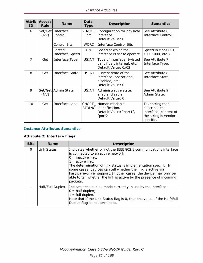
Instance Attributes
Moog Animatics Class 6 EtherNet/IP Guide, Rev. C
Page 82 of 165
AttribID
AccessRule Name Data
Type Description Semantics
6 Set/Get(NV)
Interface Control
STRUCT of:
Configuration for physical interface.Default Value: 0
See Attribute 6: Interface Control.
Control Bits WORD Interface Control Bits Forced Interface Speed
UINT Speed at which the interface is set to operate.
Speed in Mbps (10, 100, 1000, etc.)
7 Get Interface Type USINT Type of interface: twisted pair, fiber, internal, etc.Default Value: 0x02
See Attribute 7: Interface Type.
8 Get Interface State USINT Current state of the interface: operational, disabled, etc.Default Value: 0
See Attribute 8: Interface State.
9 Set/Get(NV)
Admin State USINT Administrative state: enable, disable.Default Value: 0
See Attribute 9: Admin State.
10 Get Interface Label SHORT_STRING
Human readable identification.Default Value: "port1","port2"
Text string that describes the interface; content of the string is vendor specific.
Instance Attributes Semantics
Attribute 2: Interface Flags
Bits Name Description0 Link Status Indicates whether or not the IEEE 802.3 communications interface
is connected to an active network: 0 = inactive link; 1 = active link. The determination of link status is implementation specific. In some cases, devices can tell whether the link is active via hardware/driver support. In other cases, the device may only be able to tell whether the link is active by the presence of incoming packets.
1 Half/Full Duplex Indicates the duplex mode currently in use by the interface:0 = half duplex;1 = full duplex.Note that if the Link Status flag is 0, then the value of the Half/Full Duplex flag is indeterminate.
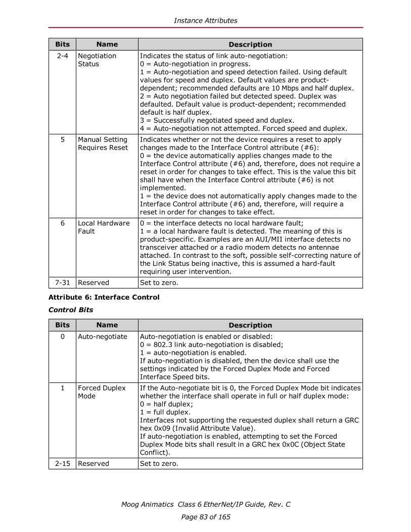
Instance Attributes
Moog Animatics Class 6 EtherNet/IP Guide, Rev. C
Page 83 of 165
Bits Name Description2-4 Negotiation
StatusIndicates the status of link auto-negotiation:0 = Auto-negotiation in progress. 1 = Auto-negotiation and speed detection failed. Using default values for speed and duplex. Default values are product-dependent; recommended defaults are 10 Mbps and half duplex.2 = Auto negotiation failed but detected speed. Duplex was defaulted. Default value is product-dependent; recommended default is half duplex.3 = Successfully negotiated speed and duplex.4 = Auto-negotiation not attempted. Forced speed and duplex.
5 Manual Setting Requires Reset
Indicates whether or not the device requires a reset to apply changes made to the Interface Control attribute (#6):0 = the device automatically applies changes made to the Interface Control attribute (#6) and, therefore, does not require a reset in order for changes to take effect. This is the value this bit shall have when the Interface Control attribute (#6) is not implemented. 1 = the device does not automatically apply changes made to the Interface Control attribute (#6) and, therefore, will require a reset in order for changes to take effect.
6 Local Hardware Fault
0 = the interface detects no local hardware fault; 1 = a local hardware fault is detected. The meaning of this is product-specific. Examples are an AUI/MII interface detects no transceiver attached or a radio modem detects no antennae attached. In contrast to the soft, possible self-correcting nature of the Link Status being inactive, this is assumed a hard-fault requiring user intervention.
7-31 Reserved Set to zero.
Attribute 6: Interface Control
Control Bits
Bits Name Description0 Auto-negotiate Auto-negotiation is enabled or disabled:
0 = 802.3 link auto-negotiation is disabled;1 = auto-negotiation is enabled. If auto-negotiation is disabled, then the device shall use the settings indicated by the Forced Duplex Mode and Forced Interface Speed bits.
1 Forced Duplex Mode
If the Auto-negotiate bit is 0, the Forced Duplex Mode bit indicates whether the interface shall operate in full or half duplex mode:0 = half duplex;1 = full duplex. Interfaces not supporting the requested duplex shall return a GRC hex 0x09 (Invalid Attribute Value). If auto-negotiation is enabled, attempting to set the Forced Duplex Mode bits shall result in a GRC hex 0x0C (Object State Conflict).
2-15 Reserved Set to zero.

Services
Moog Animatics Class 6 EtherNet/IP Guide, Rev. C
Page 84 of 165
Attribute 7: Interface Type
Value Description
0 Unknown interface type.
1 The interface is internal to the device, for example, in the case of an embedded switch.
2 Twisted-pair (e.g., 10Base-T, 100Base-TX, 1000Base-T, etc.)
3 Optical fiber (e.g., 100Base-FX)
4-255 Reserved.
Attribute 8: Interface State
Value Description0 Unknown interface type.1 The interface is enabled and is ready to send and receive data.2 The interface is disabled.3 The interface is testing.
4-255 Reserved.
Attribute 9: Admin State
Value Description0 Reserved.1 Enable the interface.2 Disable the interface.
3-255 Reserved.
Services
ServiceCode
Supported in:Name Description
Class Instance0x01 ● ● Get_Attributes_All Returns a predefined listing of this
objects attributes0x0E ● ● Get_Attribute_Single Returns the contents of the specified
attribute0x10 ● Set_Attribute_Single Modifies an attribute value.
For more details, see THE CIP NETWORKS LIBRARY, Volume 2: EtherNet/IP Adaptation of CIP, which is available on the ODVA.org website.

Application Objects
Moog Animatics Class 6 EtherNet/IP Guide, Rev. C
Page 85 of 165
Application ObjectsThe following sections/tables list the attributes for each of the Application objects (ODVA "device" set of objects).
Position Controller Supervisor (0x24) 86
Class Attributes 86
Object Instance 1 Attributes 87
Services 87
Position Controller (0x25) 88
Class Attributes 88
Instance Attributes 88
Services 92
Error Responses 92

Position Controller Supervisor (0x24)
Moog Animatics Class 6 EtherNet/IP Guide, Rev. C
Page 86 of 165
Position Controller Supervisor (0x24)The following tables provide the Class and Identity Attributes, and the Supported Services for the Position Controller Supervisor Object (0x24).
Class Attributes
AttribID
AccessRule Name Data
Type Description Semantics
1 Get Revision UINT Revision of this object.Value = 2
The current assigned value is 2. If updates require an increased value, the value increases by 1.
2 Get Max Instance UINT Maximum instance number of an object currently created in this class level of the device.
3 Get Number of Instances
UINT Number of object instances currently created at this class level of the device.
6 Get Max ID Number Class Attributes
UINT The attribute ID number of the last class attribute of the class definition implemented in the device.
7 Get Max ID Number Instance Attributes
UINT The attribute ID number of the last instance attribute of the class definition implemented in the device.
32 Get Consumed Axis Selection Number
USINT Specifies the axis number to which the data contained in the I/O Command Message is routed.
SmartMotor value is typ-ically 1 for this attribute.
33 Get Produced Axis Selection Number
USINT Specifies the axis number to which the data contained in the I/O Response Message is routed.
SmartMotor value is typ-ically 1 for this attribute.
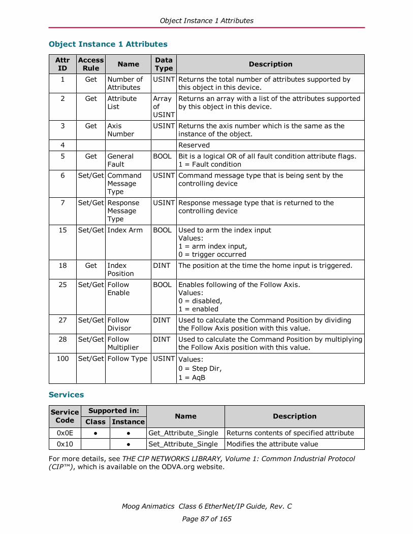
Object Instance 1 Attributes
Moog Animatics Class 6 EtherNet/IP Guide, Rev. C
Page 87 of 165
Object Instance 1 Attributes
AttrID
AccessRule Name Data
Type Description
1 Get Number of Attributes
USINT Returns the total number of attributes supported by this object in this device.
2 Get Attribute List
Array of USINT
Returns an array with a list of the attributes supported by this object in this device.
3 Get Axis Number
USINT Returns the axis number which is the same as the instance of the object.
4 Reserved5 Get General
FaultBOOL Bit is a logical OR of all fault condition attribute flags.
1 = Fault condition6 Set/Get Command
Message Type
USINT Command message type that is being sent by the controlling device
7 Set/Get Response Message Type
USINT Response message type that is returned to the controlling device
15 Set/Get Index Arm BOOL Used to arm the index inputValues:1 = arm index input,0 = trigger occurred
18 Get Index Position
DINT The position at the time the home input is triggered.
25 Set/Get Follow Enable
BOOL Enables following of the Follow Axis.Values:0 = disabled,1 = enabled
27 Set/Get Follow Divisor
DINT Used to calculate the Command Position by dividing the Follow Axis position with this value.
28 Set/Get Follow Multiplier
DINT Used to calculate the Command Position by multiplying the Follow Axis position with this value.
100 Set/Get Follow Type USINT Values:0 = Step Dir,1 = AqB
Services
ServiceCode
Supported in:Name Description
Class Instance0x0E ● ● Get_Attribute_Single Returns contents of specified attribute0x10 ● Set_Attribute_Single Modifies the attribute value
For more details, see THE CIP NETWORKS LIBRARY, Volume 1: Common Industrial Protocol (CIP™), which is available on the ODVA.org website.
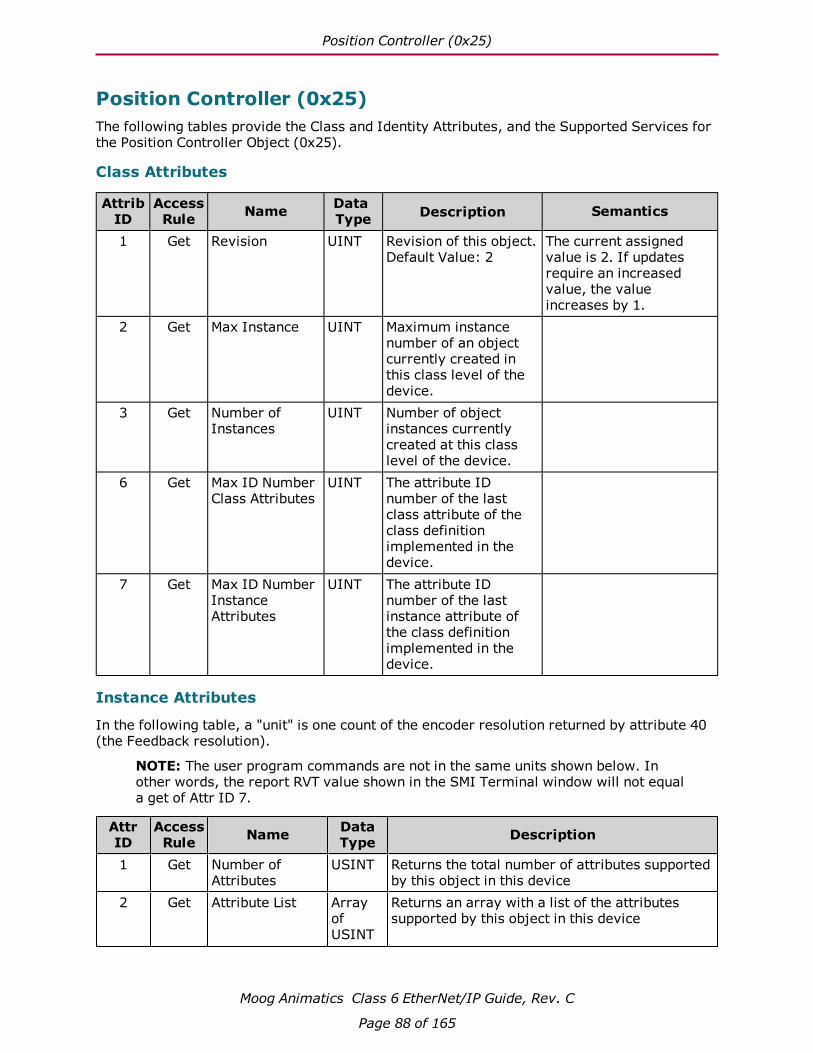
Position Controller (0x25)
Moog Animatics Class 6 EtherNet/IP Guide, Rev. C
Page 88 of 165
Position Controller (0x25)The following tables provide the Class and Identity Attributes, and the Supported Services for the Position Controller Object (0x25).
Class Attributes
AttribID
AccessRule Name Data
Type Description Semantics
1 Get Revision UINT Revision of this object.Default Value: 2
The current assigned value is 2. If updates require an increased value, the value increases by 1.
2 Get Max Instance UINT Maximum instance number of an object currently created in this class level of the device.
3 Get Number of Instances
UINT Number of object instances currently created at this class level of the device.
6 Get Max ID Number Class Attributes
UINT The attribute ID number of the last class attribute of the class definition implemented in the device.
7 Get Max ID Number Instance Attributes
UINT The attribute ID number of the last instance attribute of the class definition implemented in the device.
Instance Attributes
In the following table, a "unit" is one count of the encoder resolution returned by attribute 40 (the Feedback resolution).
NOTE: The user program commands are not in the same units shown below. In other words, the report RVT value shown in the SMI Terminal window will not equal a get of Attr ID 7.
AttrID
AccessRule Name Data
Type Description
1 Get Number of Attributes
USINT Returns the total number of attributes supported by this object in this device
2 Get Attribute List Array of USINT
Returns an array with a list of the attributes supported by this object in this device

Instance Attributes
Moog Animatics Class 6 EtherNet/IP Guide, Rev. C
Page 89 of 165
AttrID
AccessRule Name Data
Type Description
3 Set/Get Mode USINT Operating Mode:0 = Position mode (default)1 = Velocity mode2 = Torque mode
6 Set/Get Target Position DINT Profile Position value to set in Profile units (see Attr ID 40)
7 Set/Get Target Velocity DINT Profile Velocity in units/sec, positive only8 Set/Get Acceleration DINT Profile Acceleration in units/sec-sec, positive
only9 Set/Get Deceleration DINT Profile Deceleration in units/sec-sec, positive
only.10 Set/Get Incremental
Position FlagBOOL Defines Attr ID 6 as being either absolute or
incremental:0 = absolute move1 = incremental move
11 Set/Get Load Data/ Start Profile/ Profile in Progress
BOOL On set, loads data and starts the current profile. On get, reports Profile in Progress
13 Set/Get Actual Position DINT Actual absolute position. Can be Set to redefine actual position.
14 Get Actual Velocity DINT Reports actual velocity in units/sec.15 Get Commanded
PositionDINT The instantaneous calculated position
16 Get Commanded Velocity
DINT The instantaneous velocity in units/sec.
17 Set/Get Enable BOOL On the enable edge, commanded position is set to equal actual position.
Values:0=disable1=enable
20 Set/Get Smooth Stop BOOL Smooth Stop motor21 Set/Get Hard Stop BOOL Hard Stop motor23 Set/Get Direction BOOL Instantaneous Direction
Values:0=reverse1=forward
Is set to change or select direction on Velocity Mode
24 Set/Get Reference Direction
BOOL Shaft Rotation Direction (forward facing shaft):0 = CW1 = CCW
25 Set/Get Torque DINT Output Torque
Range: -32767 to 32767

Instance Attributes
Moog Animatics Class 6 EtherNet/IP Guide, Rev. C
Page 90 of 165
AttrID
AccessRule Name Data
Type Description
29 Get Wrap Around BOOL Position Wrap Around Indicator Flag
If 1, the motor has gone past its maximum position.
30 Set/Get Kp INT Proportional Gain
Range: 0 to 3276731 Set/Get Ki INT Integral Gain
Range: 0 to 3276732 Set/Get Kd INT Derivative Gain
Range: 0 to 3276733 Set/Get MaxKi INT Integration Limit
Range: 0 to 3276735 Set/Get Velocity Feed
ForwardINT Velocity feed forward gain value
Range: 0 to 3276737 Get Sample Rate INT Update sample rate in micro-seconds40 Get Feedback
ResolutionDINT Number of actual position feedback counts per
revolution41 Get Motor Resolution DINT Motor resolution in motor steps. Number of
motor steps in one revolution of the motor.45 Set/Get Max Dynamic
Following ErrorDINT Maximum allowable following error when the
motor is in motion46 Set/Get Following Error
ActionUSINT Following Error Action code:
0=Servo off1=Hard Stop2=Smooth Stop128=MTB
47 Set/Get Following Error Fault
BOOL Following error occurrence flag
48 Get Actual Following Error
DINT Actual Following error
49 Set/Get Hard Limit Action
USINT Hard Limit Action code:0 = Servo off1 = Hard Stop2 = Smooth Stop128 = MTB224 = Both hardware limits disabled
50 Get Forward Limit BOOL Forward Limit stop input status active51 Get Reverse Limit BOOL Reverse Limit stop input status active52 Set/Get Soft Limits
EnableBOOL Enables Soft Limits

Instance Attributes
Moog Animatics Class 6 EtherNet/IP Guide, Rev. C
Page 91 of 165
AttrID
AccessRule Name Data
Type Description
53 Set/Get Soft Limit Action USINT Soft Limit Action Code:0 = Servo off1 = Hard Stop2 = Smooth Stop128 = MTB
54 Set/Get Positive Soft Limit Position
DINT Soft limit positive boundary in position counts, enable BOTH soft limits
55 Set/Get Negative Soft Limit Position
DINT Soft limit negative boundary in position counts, enable BOTH soft limits
56 Get Positive Limit Triggered
BOOL Hard or Soft limit forward limit occurrence flag
57 Get Negative Limit Triggered
BOOL Hard or Soft limit forward limit occurrence flag
58 Get Load Data Complete
BOOL Valid data for a valid I/O command message type has been loaded into the position controller
100 Set/Get Current Limit DINT Current limit of motor 0 to 1023101 Set/Get Reset Motor
FaultsBOOL Set to 1 for RESET action, the Get returns the
Drive Ready Status102 Set/Get Reset Motor BOOL Set to 1 for RESET action, the Get returns the
Drive Ready Status103 Set/Get Overheat
SetpointUSINT Overheat setpoint 0-70 or 0-85 degrees C
104 Get Temperature INT Real time temperature105 Set/Get Variable u DINT Motor user variable u106 Set/Get Variable v DINT Motor user variable v107 Set/Get Variable w DINT Motor user variable w108 Set/Get Variable x DINT Motor user variable x109 Set/Get GOSUBnnn UINT Setting executes a user program command
GOSUBnnn. The Get returns the program running status.
110 Get Loss of Network Action
USINT Action if DeviceNet network heartbeat lost:0 = IGNORE (No Command)1 = OFF (Motor Off)2 = X (Smooth Stop)3 = S (Hard Stop)4 = GOSUB5 = GOTO
111 Get Status Word WORD Motor status word
112 Get Angle Match BOOL Commutation Angle Match bit

Services
Moog Animatics Class 6 EtherNet/IP Guide, Rev. C
Page 92 of 165
AttrID
AccessRule Name Data
Type Description
113 Set/Get EtherNet/IP Attribute
UINT Setting executes a user program command GOSUBnnn.
Getting returns the subroutine number (nnn) while the subroutine is executing and -1 when complete.
Only one GOSUB from the network can be active at a given time.
Executing a STACK command clears any executing GOSUB status. The motor will respond with a value of -1.
Services
ServiceCode
Supported in:Name Description
Class Instance0x0E ● ● Get_Attribute_Single Returns the contents of the specified
attribute0x10 ● Set_Attribute_Single Modifies the attribute value
Error Responses
Error Code
Additional Code
Name Description
0x02 None CIP_RESOURCE_UNAVAILABLE Attribute 113 - Network GOSUB already active
0x09 None CIP_INVALID_ATTRIB_VALUE Attribute 113 - Invalid GOSUB number
0x10 None CIP_DEVICE_STATE_CONFLICT Attribute 113 - GOSUB stack overflow
For more details, see THE CIP NETWORKS LIBRARY, Volume 1: Common Industrial Protocol (CIP™), which is available on the ODVA.org website.

Additional Objects
Moog Animatics Class 6 EtherNet/IP Guide, Rev. C
Page 93 of 165
Additional ObjectsThe following sections/tables list the attributes for the manufacturer-specific and other objects that don't fall into the previous categories.
Device Level Ring (DLR) Object (0x47) 94
Class Attributes 94
Instance Attributes 94
Services 95
QoS Object (0x48) 96
Class Attributes 96
Instance Attributes 96
Services 97
SmartMotor I/O Object (0x71) 98
Attribute Table (Instance 0) 98
Attribute Table (One instance per I/O pin) 98
SmartMotor User Variable Object (0x72) 99
Class Attribute (Instance 0) 99
Instance Attributes (Instance 1-7) 100
Semantics 100
Error Responses 100
Instance Descriptions 101
Examples 102
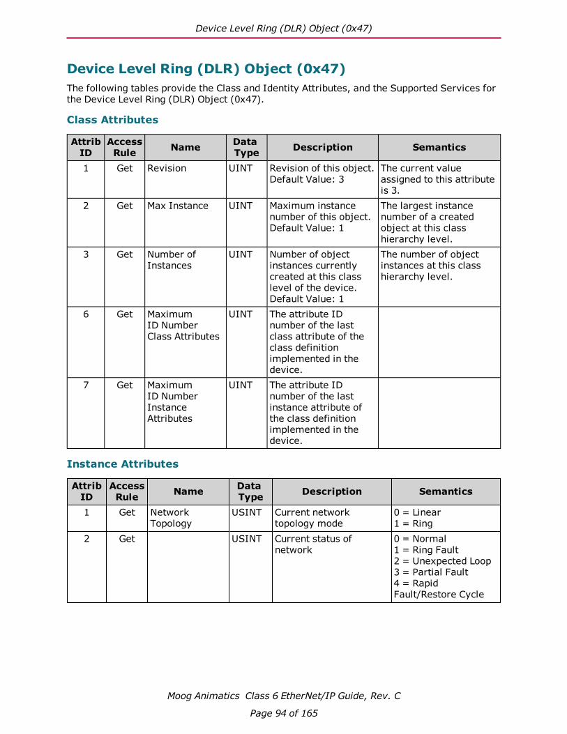
Device Level Ring (DLR) Object (0x47)
Moog Animatics Class 6 EtherNet/IP Guide, Rev. C
Page 94 of 165
Device Level Ring (DLR) Object (0x47)The following tables provide the Class and Identity Attributes, and the Supported Services for the Device Level Ring (DLR) Object (0x47).
Class Attributes
AttribID
AccessRule Name Data
Type Description Semantics
1 Get Revision UINT Revision of this object.Default Value: 3
The current value assigned to this attribute is 3.
2 Get Max Instance UINT Maximum instance number of this object.Default Value: 1
The largest instance number of a created object at this class hierarchy level.
3 Get Number of Instances
UINT Number of object instances currently created at this class level of the device.Default Value: 1
The number of object instances at this class hierarchy level.
6 Get Maximum ID Number Class Attributes
UINT The attribute ID number of the last class attribute of the class definition implemented in the device.
7 Get Maximum ID Number Instance Attributes
UINT The attribute ID number of the last instance attribute of the class definition implemented in the device.
Instance Attributes
AttribID
AccessRule Name Data
Type Description Semantics
1 Get Network Topology
USINT Current network topology mode
0 = Linear 1 = Ring
2 Get USINT Current status of network
0 = Normal 1 = Ring Fault2 = Unexpected Loop 3 = Partial Fault4 = Rapid Fault/Restore Cycle

Services
Moog Animatics Class 6 EtherNet/IP Guide, Rev. C
Page 95 of 165
AttribID
AccessRule Name Data
Type Description Semantics
10 Get Active Supervisor Address
STRUCT of:
IP and/or MAC address of the active ring supervisor.Default Value: 0
UDINT Supervisor IP Address 0 = No configured IP address
ARRAY of 6 USINTs
Supervisor MAC Address Ethernet MAC address
12 Get Capability Flags DWORD Describes the DLR capabilities of the device
See below: Attribute 12: Capability Flags
Instance Attributes Semantics
Attribute 12: Capability Flags
Bits Name Description0 Announce-based Ring Node1 Set if device’s ring node implementation is
based on processing of Announce frames.1 Beacon-based Ring Node1 Set if device’s ring node implementation is
based on processing of Beacon frames.2-4 Reserved Set to zero.5 Supervisor Capable Set if device is capable of providing the
supervisor function.6 Redundant Gateway Capable Set if device is capable of providing the
redundant gateway function.7 Flush_Table frame Capable Set if device is capable of supporting the Flush_
Tables frame.8-31 Reserved Set to zero.
1. Bits 0 and 1 are mutually exclusive. Only one of these bits can be set in the attribute value that a device reports.
Services
ServiceCode
Supported in:Name Description
Class Instance0x01 ● Get_Attributes_All Returns a predefined listing of this
objects attributes0x0E ● ● Get_Attribute_Single Returns the contents of the specified
attribute
For more details, see THE CIP NETWORKS LIBRARY, Volume 1: Common Industrial Protocol (CIP™), which is available on the ODVA.org website.

QoS Object (0x48)
Moog Animatics Class 6 EtherNet/IP Guide, Rev. C
Page 96 of 165
QoS Object (0x48)The following tables provide the Class and Identity Attributes, and the Supported Services for the QoS Object (0x48).
Class Attributes
AttribID
AccessRule Name Data
Type Description Semantics
1 Get Revision UINT Revision of this object.Default Value: 3
The current assigned value is 1. If updates require an increased value, the value increases by 1.
2 Get Max Instance UINT Maximum instance number of this object.Default Value: 1
The largest instance number of a created object at this class hierarchy level.
3 Get Number of Instances
UINT Number of object instances currently created at this class level of the device.Default Value: 1
The number of object instances at this class hierarchy level.
6 Get Maximum ID Number Class Attributes
UINT The attribute ID number of the last class attribute of the class definition implemented in the device.
7 Get Maximum ID Number Instance Attributes
UINT The attribute ID number of the last instance attribute of the class definition implemented in the device.
Instance Attributes
AttribID
AccessRule Name Data
Type Description Semantics
1a Set/Get(NV)
802.1Q Tag Enable
USINT Enables or disables sending 802.1Q frames on CIP and IEEE 1588 messages.Default Value: 0
0 = disabled1 = enabledValue change takes effect the next time the device restarts.
2 Set/Get(NV)
DSCP PTP Event USINT DSCP value for PTP (IEEE 1588) event messages.Default Value: 59
DSCP field size is 6 bits, valid range: 0-63
3 Set/Get(NV)
DSCP PTP General
USINT DSCP value for PTP (IEEE 1588) general messages.Default Value: 47
DSCP field size is 6 bits, valid range: 0-63

Services
Moog Animatics Class 6 EtherNet/IP Guide, Rev. C
Page 97 of 165
AttribID
AccessRule Name Data
Type Description Semantics
4 Set/Get(NV)
DSCP Urgent USINT DSCP value for CIP transport class 0/1 urgent priority messages.Default Value: 55
DSCP field size is 6 bits, valid range: 0-63
5 Set/Get(NV)
DSCP Scheduled USINT DSCP value for CIP transport class 0/1 scheduled priority messages.Default Value: 47
DSCP field size is 6 bits, valid range: 0-63
6 Set/Get(NV)
DSCP High USINT DSCP value for CIP transport class 0/1 high priority messages.Default Value: 43
DSCP field size is 6 bits, valid range: 0-63
7 Set/Get(NV)
DSCP Low USINT DSCP value for CIP transport class 0/1 low priority messages.Default Value: 31
DSCP field size is 6 bits, valid range: 0-63
8 Set/Get(NV)
DSCP Explicit USINT DSCP value for CIP explicit messages (transport class 2/3 and UCMM) and all other EtherNet/IP encapsulation messages.Default Value: 27
DSCP field size is 6 bits, valid range: 0-63
a. The 802.1Q VLAN tagging mechanism can be turned on and off by setting or clearing the value of attribute 1 (802.1Q Tag Enable) of the QoS object.
Services
ServiceCode
Supported in:Name Description
Class Instance0x0E ● ● Get_Attribute_Single Returns the contents of the specified
attribute
0x10 ● Set_Attribute_Single Modifies the contents of the specified attribute
For more details, see THE CIP NETWORKS LIBRARY, Volume 2: EtherNet/IP Adaptation of CIP, which is available on the ODVA.org website.

SmartMotor I/O Object (0x71)
Moog Animatics Class 6 EtherNet/IP Guide, Rev. C
Page 98 of 165
SmartMotor I/O Object (0x71)The following tables describe the attributes and instances for the SmartMotor I/O Object (0x71).
Attribute Table (Instance 0)
AttrID
AccessRule Name Data
Type Description Semantics
1 Get Revision UINT Revision of this object.Default Value: 1
The current value assigned to this attribute is 1.
2 Get Max Instance UINT Maximum instance number of this object.Default Value: 1
The largest instance number of a created object at this class hierarchy level.
3 Get Number of Instances
UINT Number of object instances currently created at this class level of the device.Default Value: 1
The number of object instances at this class hierarchy level.
6 Get Maximum ID Number Class Attributes
UINT The attribute ID number of the last class attribute of the class definition implemented in the device.
7 Get Maximum ID Number Instance Attributes
UINT The attribute ID number of the last instance attribute of the class definition implemented in the device.
8 Get I/O Word State
WORD Returns the value of first 16 I/O points; bit 0 is I/O 0 (zero)
Attribute Table (One instance per I/O pin)
AttrID
AccessRule Name Data
Type Description Semantics
1 Set/Get Function USINT Sets (or gets) the function as Output, Input or Special.
Values:1 = Input2 = Special
2 Set/Get Output State BOOL Sets (or gets) the output states as ON or OFF.
Values:0 = OFF1 = ON
3 Get I/O State BOOL Returns present state of the I/O, either ON or OFF.
Values:0 = OFF1 = ON
4 Get Analog Raw Value
INT Hardware dependent

SmartMotor User Variable Object (0x72)
Moog Animatics Class 6 EtherNet/IP Guide, Rev. C
Page 99 of 165
Instance I/O Number Function1 0 – Input 2 1 – Input 3 2 – Input Positive Limit4 3 – Input Negative Limit5 4 – Input 6 5 – Input 7 6 – Input Go8 7 – Input Drive Enable9 8 – Output External Brake10 9 – Output Fault
SmartMotor User Variable Object (0x72)The following tables describe the attributes and instances for the SmartMotor User Variable Object (0x72). This object allows access to all defined User Variables with an explicit message. See the Instance Description table below for details of the Instance and Attribute values needed to address a particular User Variable.
Class Attribute (Instance 0)
AttrID
AccessRule Name Data
Type Description Semantics
1 Get Revision UINT Revision of this object.Default Value: 1
The current value assigned to this attribute is 1.
2 Get Max Instance
UINT Maximum instance number of this object.Default Value: 7
The largest instance number of a created object at this class hierarchy level.
3 Get Number of Instances
UINT Number of object instances currently created at this class level of the device.Default Value: 7
The number of object instances at this class hierarchy level.

Instance Attributes (Instance 1-7)
Moog Animatics Class 6 EtherNet/IP Guide, Rev. C
Page 100 of 165
Instance Attributes (Instance 1-7)
AttrID
AccessRule Name Data
Type Description Semantics
1 Get Instance Name
SHORT-STRING
A human–readable string representing the instance name. (E.G., a-z, aa-zz, etc.)
See below
2 Get Number of User Variables
UINT Number of User Variables in this instance
3 Get/Set 1st User Variable for this Instance
SINT, INT, DINT, REAL depending on instance
Returns/Sets the value of the 1st user variable for the selected instance
... n Get/Set Last User
Variable for this Instance
SINT, INT, DINT, REAL depending on instance
Returns/Sets the value of the 1st user variable for the selected instance
See below.
Semantics
Instance Attribute 1: Instance NameA human readable string representing the block of user variables being accessed. This value is returned as a SHORT-STRING, a 1-byte length (SINT) followed by up to 16 ASCII bytes of data.
Instance Attribute 3 - n: User Variable ValueThere is one Instance Attribute for each User Variable in the Instance.
Error Responses
Error Code
Additional Code
Name Description
0x08 None CIP_SERVICE_NOT_SUPPORTED Invalid Service value
0x0E None CIP_ATTRIBUTE_NOT_SETTABLE Attribute Not settable
0x13 None CIP_NOT_ENOUGH_DATA Source Length is too small
0x14 None CIP_ATTRIBUTE_NOT_SUPPORTED Invalid Attribute number
0x15 None CIP_TOO_MUCH_DATA Source Length is too large
0x16 None CIP_OBJECT_DOES_NOT_EXIST Invalid Instance number

Instance Descriptions
Moog Animatics Class 6 EtherNet/IP Guide, Rev. C
Page 101 of 165
Instance Descriptions
User Variable
Size
4-bytes DINT
4-bytes DINT
4-bytes DINT
4-bytes DINT
2-bytes INT
1-byte SINT
4-bytes REAL
Attribute Instance 1
Instance 2
Instance 3
Instance 4
Instance 5
Instance 6
Instance 7
1 "a-z" "aa-zz" "aaa-zzz" "al" "aw" "ab" "af"2 26 26 26 51 102 204 83 a aa aaa al[0] aw[0] ab[0] af[0]4 b bb bbb al[1] aw[1] ab[1] af[1]5 c cc ccc al[2] aw[2] ab[2] af[2]6 d dd ddd al[3] aw[3] ab[3] af[3]7 e ee eee al[4] aw[4] ab[4] af[4]
8 f ff fff al[5] aw[5] ab[5] af[5]
9 g gg ggg al[6] aw[6] ab[6] af[6]
10 h hh hhh al[7] aw[7] ab[7] af[7]
11 i ii iii al[8] aw[8] ab[8]
12 j jj jjj al[9] aw[9] ab[9]
13 k kk kkk al[10] aw[10] ab[10]
14 l ll lll al[11] aw[11] ab[11]
15 m mm mmm al[12] aw[12] ab[12]
16 n nn nnn al[13] aw[13] ab[13]
17 o oo ooo al[14] aw[14] ab[14]
18 p pp ppp al[15] aw[15] ab[15]
19 q qq qqq al[16] aw[16] ab[16]
20 r rr rrr al[17] aw[17] ab[17]
21 s ss sss al[18] aw[18] ab[18]
22 t tt ttt al[19] aw[19] ab[19]
23 u uu uuu al[20] aw[20] ab[20]
24 v vv vvv al[21] aw[21] ab[21]
25 w ww www al[22] aw[22] ab[22]
26 x xx xxx al[23] aw[23] ab[23]
27 y yy yyy al[24] aw[24] ab[24]
28 z zz zzz al[25] aw[25] ab[25]
... ... ... ...
n al[50] aw[101] ab[203]
For Instances 4 through 7, n = User Variable Index + 3

Examples
Moog Animatics Class 6 EtherNet/IP Guide, Rev. C
Page 102 of 165
Examples
Letter User Variables
The following Rockwell RSLogix 500 ladder logic snippets and Explicit Message configurations demonstrate how to access the Letter User Variables (a-z, aa-zz, aaa-zzz).
Get User Variable jj
The following table describes the Message Configuration fields that must be filled in.
Field Instructions
Message Type Must be "CIP Generic"
Service Type Must be "Get Attribute Single"
Class Must be 72(hex); this field is entered as a hexadecimal number on the configuration screen
Attribute Selects the user variable to access; this field is entered as a hexa-decimal number on the configuration screen
Instance Selects the block of user variables to access
Destination element The PLC tag where the data will be stored; the size of the tag entered in this field should match the number of bytes being retrieved. The top of each column in the "Instance Description table" indicates the number of bytes of data retrieved for each instance and the equi-valent data type used in the PLC program.

Examples
Moog Animatics Class 6 EtherNet/IP Guide, Rev. C
Page 103 of 165
Set User Variable jj to a value of 123456
The following table describes the Message Configuration fields that must be filled in.
Field Instructions
Message Type Must be "CIP Generic"
Service Type Must be "Get Attribute Single"
Class Must be 72(hex); this field is entered as a hexadecimal number on the configuration screen
Instance Selects the block of user variables to access
Attribute Selects the user variable to access; this field is entered as a hexa-decimal number on the configuration screen
Source element Indicates the PLC tag with the data to send
Source Length The number of bytes of data to send; this field must match the num-ber of bytes in the User Variable being set. The top of each column in the "Instance Description table" indicates the number of bytes of data to send for each user variable instance and the equivalent data type used in the PLC program.

Examples
Moog Animatics Class 6 EtherNet/IP Guide, Rev. C
Page 104 of 165
Array User Variables
The following Rockwell RSLogix 500 ladder logic snippets and Explicit Message configurations demonstrate how to access the Array User Variables (al, aw, ab, af).
Get User Variable ab[77]
The following table describes the Message Configuration fields that must be filled in.
Field Instructions
Message Type Must be "CIP Generic"
Service Type Must be "Get Attribute Single"
Class Must be 72(hex); this field is entered as a hexadecimal number on the configuration screen
Attribute Selects the user variable to access; this field is entered as a hexa-decimal number on the configuration screen
Instance Selects the block of user variables to access
Destination element The PLC tag where the data will be stored; the size of the tag entered in this field should match the number of bytes being retrieved. The top of each column in the "Instance Description table" indicates the number of bytes of data retrieved for each instance and the equi-valent data type used in the PLC program.

Examples
Moog Animatics Class 6 EtherNet/IP Guide, Rev. C
Page 105 of 165
Set User Variable ab[77] to a value of -125.
The following table describes the Message Configuration fields that must be filled in.
Field Instructions
Message Type Must be "CIP Generic"
Service Type Must be "Get Attribute Single"
Class Must be 72(hex); this field is entered as a hexadecimal number on the configuration screen
Instance Selects the block of user variables to access
Attribute Selects the user variable to access; this field is entered as a hexa-decimal number on the configuration screen
Source element Indicates the PLC tag with the data to send
Source Length The number of bytes of data to send; this field must match the num-ber of bytes in the User Variable being set. The top of each column in the "Instance Description table" indicates the number of bytes of data to send for each user variable instance and the equivalent data type used in the PLC program.

AOI Descriptions - Allen Bradley PLC
AOI Descriptions - Allen Bradley PLCThis chapter describes the Add On Instructions (AOIs) that are available for use with the EtherNet/IP SmartMotor and Allen Bradley PLCs. The AOIs can be used "as is" or modified for end-user-specific solutions.
NOTE: Typically, only one AOI should be active at a time.
The AOIs write to a common command structure stored in the DriveStore tag, which is initialized in the SM6_Drive AOI and passed into all the other AOIs. The exception to this is when a 32-byte connection is used. The 32-byte message frames make available the Attribute to Get fields. When loaded with proper values, the Attribute to Get fields cause the targeted drive to return the value of a selected Drive Attribute in the Attribute to Get fields of the response. The Attribute to Get fields can be used in conjunction with the normal command/response fields.
Moog Animatics Class 6 EtherNet/IP Guide, Rev. C
Page 106 of 165

AOI Descriptions - Allen Bradley PLC
SM6_Attribute_Ext_Clear - Clear Attribute to Get (Extended Command) 108
SM6_Attribute_Ext_Get - Load Attribute to Get ID & Wait (Extended Com-mand) 109
SM6_Attribute_Ext_Load - Load Attribute to Get ID (Extended Command) 110
SM6_Attribute_Ext_Value - Return Attribute data (Extended Command) 112
SM6_Clear_Flags - Reset System State Flag 114
SM6_Disable - Disable Drive 115
SM6_Drive - Drive Data Exchange 116
SM6_Enable - Enable Drive 118
SM6_Get_Attribute - Get Drive Attribute 119
SM6_Move_Position_Ext - Position Move(Extended Command) 120
SM6_Move_Velocity_Ext - Velocity Move(Extended Command) 122
SM6_Move_Torque - Apply Torque 124
SM6_Set_Acceleration - Set Drive Acceleration 125
SM6_Set_Attribute - Set Drive Attribute 126
SM6_Set_Deceleration - Set Drive Deceleration 127
SM6_Set_Mode - Set Drive Mode 128
SM6_Set_Position - Set Drive Position 129
SM6_Set_Variable_u - Set Drive Variable "u" 130
SM6_Set_Velocity - Set Drive Target Velocity 131
SM6_Stop_Hard - Perform a Hard Stop 132
SM6_Stop_Smooth - Perform a Smooth Stop 133
Moog Animatics Class 6 EtherNet/IP Guide, Rev. C
Page 107 of 165

SM6_Attribute_Ext_Clear - Clear Attribute to Get (Extended Command)
SM6_Attribute_Ext_Clear - Clear Attribute to Get (Extended Command)
Description
Clears the Extended Attribute to Get fields in the Axis Command buffer. This will cause the drive to clear the Attribute to Get fields in the Response buffer.
Operands
Operand Data Type Operand Type Description
SM6_Attribute_Ext_Clear SM6_Attribute_Ext_Clear Tag Control tag for this AOI
Axis SM6_Axis Tag The targeted drive
Structure
Field Type Description
.DN BOOL Set when the drive indicates the instruction has been processed.
.ER BOOL Set if there are any timeout or processing errors.
Operation
Scan Mode Description
Prescan Initialize variables.
Rung-condition-in is FALSE Initialize variables.
Rung-condition-in is TRUE Clears the Extended Attribute to Get fields in the Axis Command buffer.
NOTE: This command requires a connection size of 32 bytes.
Moog Animatics Class 6 EtherNet/IP Guide, Rev. C
Page 108 of 165

SM6_Attribute_Ext_Get - Load Attribute to Get ID & Wait (Extended Command)
SM6_Attribute_Ext_Get - Load Attribute to Get ID & Wait (Extended Command)
Description
Use the Extended Attribute to Get Type and ID fields to get the value of the requested Attribute and copy the response to the Attribute_Value tag.Operands
Operand Data Type Operand Type Description
SM6_Attribute_Ext_Get SM6_Attribute_Ext_Get Tag Control tag for this AOI
Axis SM6_Axis Tag The targeted drive
Message_Type SINT Immediate Value
16#1a - Position Controller Supervisor16#1b - Position Controller
Attribute_ID DINT Immediate Value
The index to one of these application objects: Pos-ition Controller Supervisor (0x24) on page 86 or Pos-ition Controller (0x25) on page 88.
Attribute_Value DINT Tag The value of the attribute.
Structure
Field Type Description
.DN BOOL Set when the drive indicates the instruction has been processed.
.ER BOOL Set if there are any timeout or processing errors.
Operation
Scan Mode Description
Prescan Initialize variables.
Rung-condition-in is FALSE Initialize variables.
Rung-condition-in is TRUE Load the Extended Attribute to Get Type and ID fields, wait for a response, copy the response to the Attribute_Value tag, clear the Extended Attribute to Get Type and ID fields.
NOTE: This command requires a connection size of 32 bytes.
Moog Animatics Class 6 EtherNet/IP Guide, Rev. C
Page 109 of 165
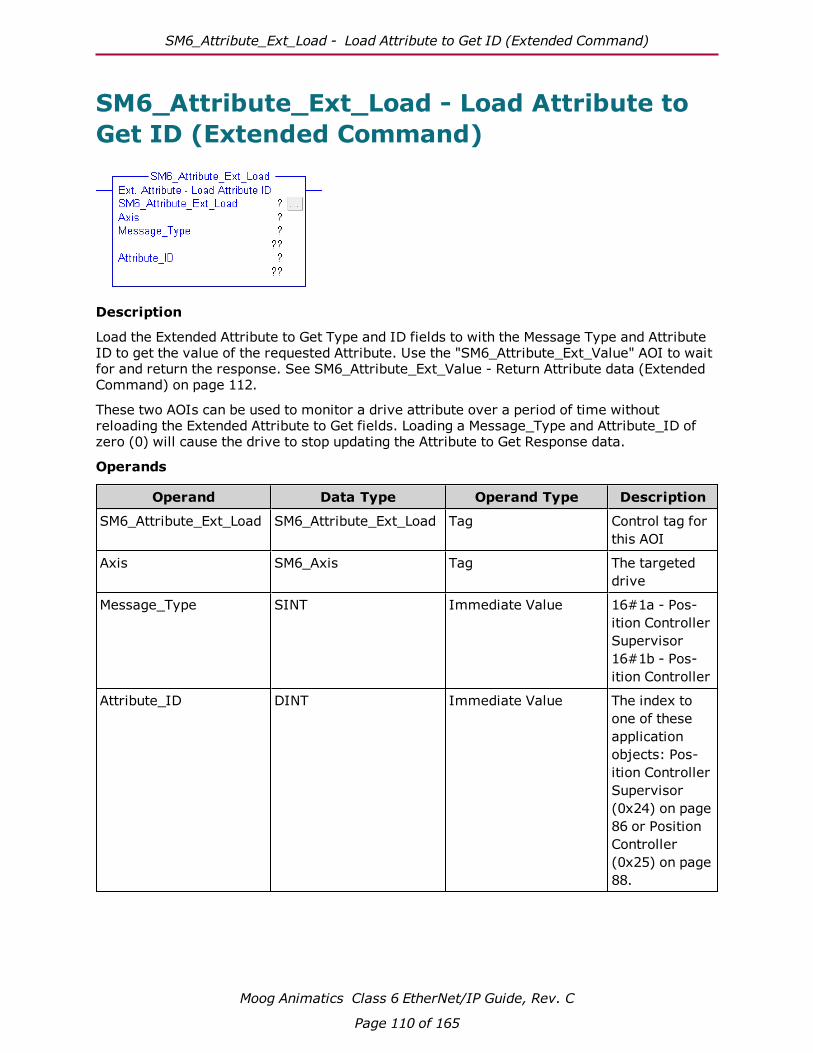
SM6_Attribute_Ext_Load - Load Attribute to Get ID (Extended Command)
SM6_Attribute_Ext_Load - Load Attribute to Get ID (Extended Command)
Description
Load the Extended Attribute to Get Type and ID fields to with the Message Type and Attribute ID to get the value of the requested Attribute. Use the "SM6_Attribute_Ext_Value" AOI to wait for and return the response. See SM6_Attribute_Ext_Value - Return Attribute data (Extended Command) on page 112.
These two AOIs can be used to monitor a drive attribute over a period of time without reloading the Extended Attribute to Get fields. Loading a Message_Type and Attribute_ID of zero (0) will cause the drive to stop updating the Attribute to Get Response data.
Operands
Operand Data Type Operand Type Description
SM6_Attribute_Ext_Load SM6_Attribute_Ext_Load Tag Control tag for this AOI
Axis SM6_Axis Tag The targeted drive
Message_Type SINT Immediate Value 16#1a - Pos-ition Controller Supervisor16#1b - Pos-ition Controller
Attribute_ID DINT Immediate Value The index to one of these application objects: Pos-ition Controller Supervisor (0x24) on page 86 or Position Controller (0x25) on page 88.
Moog Animatics Class 6 EtherNet/IP Guide, Rev. C
Page 110 of 165
SM6_Attribute_Ext_Load - Load Attribute to Get ID (Extended Command)
Structure
Field Type Description
N/A
Operation
Scan Mode Description
Prescan N/A
Rung-condition-in is FALSE N/A
Rung-condition-in is TRUE Copy Message_Type and Attribute ID to the Extended Attribute to Get fields of the Axis Command buffer
NOTE: This command requires a connection size of 32 bytes.
Moog Animatics Class 6 EtherNet/IP Guide, Rev. C
Page 111 of 165

SM6_Attribute_Ext_Value - Return Attribute data (Extended Command)
SM6_Attribute_Ext_Value - Return Attribute data (Extended Command)
Description
Returns the Extended Attribute to Get response value for the current axis.
l When the Extended Attribute to Get Message Type in the axis command buffer is zero then a value of zero is returned.
l When the Extended Attribute to Get Message Type in the axis command buffer does not match the Message Type in the axis response buffer the .IP flag will be set (1) and the .DN flag will be clear (0).
l When the Extended Attribute to Get Message Type in the axis command buffer matches the Message Type in the axis response buffer the .IP flag will be clear (0) and the .DN flag will be set (1).
Operands
Operand Data Type Operand Type Description
SM6_Attribute_Ext_Value
SM6_Attribute_Ext_Value
Tag Control tag for this AOI
Axis SM6_Axis Tag The targeted drive
Attribute_Value DINT Tag The value of the attrib-ute.
Structure
Field Type Description
.DN BOOL Set when the drive indicates the instruction has been processed.
.ER BOOL Set if there are any timeout or processing errors.
.IP BOOL Set when the Extended Attribute to Get Message Type in the axis command buf-fer is not zero and does not match the Extended Attribute to Get Message Type in the axis response buffer.
Moog Animatics Class 6 EtherNet/IP Guide, Rev. C
Page 112 of 165

SM6_Attribute_Ext_Value - Return Attribute data (Extended Command)
Operation
Scan Mode Description
Prescan Initialize variables.
Rung-condition-in is FALSE Initialize variables.
Rung-condition-in is TRUE Wait for a response from the drive, copy the response Attrib-ute_Value tag, clear the Extended Attribute to Get Type and ID fields.
NOTE: This command requires a connection size of 32 bytes.
Moog Animatics Class 6 EtherNet/IP Guide, Rev. C
Page 113 of 165
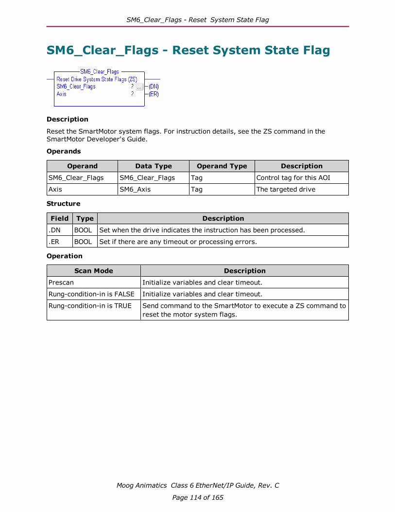
SM6_Clear_Flags - Reset System State Flag
SM6_Clear_Flags - Reset System State Flag
Description
Reset the SmartMotor system flags. For instruction details, see the ZS command in the SmartMotor Developer's Guide.
Operands
Operand Data Type Operand Type Description
SM6_Clear_Flags SM6_Clear_Flags Tag Control tag for this AOI
Axis SM6_Axis Tag The targeted drive
Structure
Field Type Description
.DN BOOL Set when the drive indicates the instruction has been processed.
.ER BOOL Set if there are any timeout or processing errors.
Operation
Scan Mode Description
Prescan Initialize variables and clear timeout.
Rung-condition-in is FALSE Initialize variables and clear timeout.
Rung-condition-in is TRUE Send command to the SmartMotor to execute a ZS command to reset the motor system flags.
Moog Animatics Class 6 EtherNet/IP Guide, Rev. C
Page 114 of 165

SM6_Disable - Disable Drive
SM6_Disable - Disable Drive
Description
Clear the Axis Drive Enable flag and wait for the Axis Drive Status flag to indicate the drive is disabled.
Operands
Operand Data Type Operand Type Description
SM6_Disable SM6_Disable Tag Control tag for this AOI
Axis SM6_Axis Tag The targeted drive
Structure
Field Type Description
.DN BOOL Set when the drive indicates the instruction has been processed.
.ER BOOL Set if there are any timeout errors.
Operation
Scan Mode Description
Prescan Reset timeout.
Rung-condition-in is FALSE Reset timeout.
Rung-condition-in is TRUE Clear the Axis Drive Enable flag. Set the .DN output when the Axis Drive Status Enable flag is cleared.
Moog Animatics Class 6 EtherNet/IP Guide, Rev. C
Page 115 of 165

SM6_Drive - Drive Data Exchange
SM6_Drive - Drive Data Exchange
Description
This AOI manages the connections to the drive.
l The Response from the drive is copied from the Drive Input tag and stored in the Response buffer of the Drive Store tag.
l The Drive Status data is extracted and copied to the Drive Store Status variable.
l The Drive Response data is extracted and copied to the Drive Store Response data variables.
l (32-byte connections only) The Attribute to Get data is retrieved from the response if the Attribute to Get fields are set in the Drive Store Command buffer.
l The Drive Output connection is loaded from the Drive Store Command buffer.
Operands
Operand Data Type Operand Type Description
SM6_Drive SM6_Drive Tag Control tag for this AOI
Axis SM6_Axis Tag The targeted drive
DriveInput _032A:Class6_xxxxxxxx:I:0
Tag Module defined Input Con-nection tag to Drive Response data
DriveOutput _032A:Class6_xxxxxxxx:O:0
Tag Module defined Output Con-nection tag to Drive Com-mand data
DriveStore SM6_Axis Tag Tag to Store Axis Com-mand and Response data
Structure
Field Type Description
N/A
Moog Animatics Class 6 EtherNet/IP Guide, Rev. C
Page 116 of 165
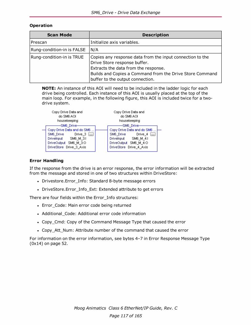
SM6_Drive - Drive Data Exchange
Operation
Scan Mode Description
Prescan Initialize axis variables.
Rung-condition-in is FALSE N/A
Rung-condition-in is TRUE Copies any response data from the input connection to the Drive Store response buffer.Extracts the data from the response.Builds and Copies a Command from the Drive Store Command buffer to the output connection.
NOTE: An instance of this AOI will need to be included in the ladder logic for each drive being controlled. Each instance of this AOI is usually placed at the top of the main loop. For example, in the following figure, this AOI is included twice for a two-drive system.
Error Handling
If the response from the drive is an error response, the error information will be extracted from the message and stored in one of two structures within DriveStore:
l Drivestore.Error_Info: Standard 8-byte message errors
l DriveStore.Error_Info_Ext: Extended attribute to get errors
There are four fields within the Error_Info structures:
l Error_Code: Main error code being returned
l Additional_Code: Additional error code information
l Copy_Cmd: Copy of the Command Message Type that caused the error
l Copy_Att_Num: Attribute number of the command that caused the error
For information on the error information, see bytes 4–7 in Error Response Message Type (0x14) on page 52.
Moog Animatics Class 6 EtherNet/IP Guide, Rev. C
Page 117 of 165

SM6_Enable - Enable Drive
SM6_Enable - Enable Drive
Description
Set the Axis Drive Enable flag and wait for the Axis Drive Status flag to indicate the drive is enabled.
Operands
Operand Data Type Operand Type Description
SM6_Enable SM6_Enable Tag Control tag for this AOI
Axis SM6_Axis Tag The targeted drive
Structure
Field Type Description
.DN BOOL Set when the drive indicates the instruction has been processed.
.ER BOOL Set if there are any timeout errors.
Operation
Scan Mode Description
Prescan Reset timeout.
Rung-condition-in is FALSE Reset timeout.
Rung-condition-in is TRUE Set the Axis Drive Enable flag. Set the .DN output when the Axis Drive Status Enable flag is set.
Moog Animatics Class 6 EtherNet/IP Guide, Rev. C
Page 118 of 165

SM6_Get_Attribute - Get Drive Attribute
SM6_Get_Attribute - Get Drive Attribute
Description
Get the value of the requested Attribute and copy the response to the Attribute_Value tag.
Operands
Operand Data Type Operand Type Description
SM6_Get_Attribute SM6_Get_Attribute Tag Control tag for this AOI
Axis SM6_Axis Tag The targeted drive
Message_Type SINT Immediate Value
16#1a - Position Controller Super-visor16#1b - Position Controller
Attribute_ID DINT Immediate Value
The index to one of these application objects: Position Controller Super-visor (0x24) on page 86 or Position Controller (0x25) on page 88.
Attribute_Value DINT Tag The value of the attribute
Structure
Field Type Description
.DN BOOL Set when the drive indicates the instruction has been processed.
.ER BOOL Set if there are any timeout or processing errors.
Operation
Scan Mode Description
Prescan Initialize variables.
Rung-condition-in is FALSE Initialize variables and reset timeout.
Rung-condition-in is TRUE Send a message to the SmartMotor to get the value of a Pos-ition Controller Supervisor or Position Controller object attrib-ute, wait for a response, copy the response to the Attribute_Value tag.
Moog Animatics Class 6 EtherNet/IP Guide, Rev. C
Page 119 of 165

SM6_Move_Position_Ext - Position Move(Extended Command)
SM6_Move_Position_Ext - Position Move(Extended Command)
Description
Send a message to the SmartMotor to generate a profile move to an absolute or relative position. The message can also specify a standard data response.
NOTE: The 32-byte Extended Response Message always includes the Actual Position and Actual Velocity. See the Polled I/O: Produced General Message Format on page 48.
Operands
Operand Data Type Operand Type Description
SM6_Move_Position_Ext SM6_Move_Position_Ext Tag Control tag for this AOI
Axis SM6_Axis Tag The targeted drive
Incremental BOOL Immediate Value Move Type0 - Absolute 1 - Incremental
Target_Position DINT Tag Requested Position
Target_Acceleration DINT Tag Requested Acceleration
Target_Deceleration DINT Tag Requested Deceleration
Target_Velocity DINT Tag Requested Velocity
Response_Type SINT Immediate Value 0 - None1 - Actual Position2 - Command Position3 - Actual Velocity4 - Command Velocity5 - Torque
Moog Animatics Class 6 EtherNet/IP Guide, Rev. C
Page 120 of 165

SM6_Move_Position_Ext - Position Move(Extended Command)
Structure
Field Type Description
.DN BOOL Set when the drive indicates the instruction has been processed.
.ER BOOL Set if there are any timeout or processing errors.
.IP BOOL In Progress—set while the drive is reporting a command is in progress.
.MC BOOL Move Complete—set when there is no move in progress and the drive is on the target position.
Operation
Scan Mode Description
Prescan Initialize variables.
Rung-condition-in is FALSE Initialize variables.
Rung-condition-in is TRUE Send the Extended Move Position message to the drive and mon-itor move progress.
NOTE: This command requires a connection size of 32 bytes.
Moog Animatics Class 6 EtherNet/IP Guide, Rev. C
Page 121 of 165

SM6_Move_Velocity_Ext - Velocity Move(Extended Command)
SM6_Move_Velocity_Ext - Velocity Move(Extended Command)
Description
Send a message to the SmartMotor to generate a profile move to a requested Velocity.
NOTE: The 32-byte Extended Response Message always includes the Actual Velocity. See the Polled I/O: Produced General Message Format on page 48.
Operands
Operand Data Type Operand Type Description
SM6_Move_Velocity_Ext SM6_Move_Velocity_Ext Tag Control tag for this AOI
Axis SM6_Axis Tag The targeted drive
Direction BOOL Immediate Value Requested Direction0=Reverse1=Forward
Target_Acceleration DINT Tag Requested Acceleration
Target_Deceleration DINT Tag Requested Deceleration
Target_Velocity DINT Tag Requested Velocity
Response_Type SINT Immediate Value 0 - None1 - Actual Velocity2 - Command Velocity3 - Actual Velocity4 - Command Velocity5 - Torque
Structure
Field Type Description
.DN BOOL Set when the drive indicates the instruction has been processed.
.ER BOOL Set if there are any timeout or processing errors.
.IP BOOL In Progress—set while the drive is reporting a command is in progress.
Moog Animatics Class 6 EtherNet/IP Guide, Rev. C
Page 122 of 165

SM6_Move_Velocity_Ext - Velocity Move(Extended Command)
Operation
Scan Mode Description
Prescan Initialize variables.
Rung-condition-in is FALSE Initialize variables and reset timeout.
Rung-condition-in is TRUE Send the Extended Move Velocity message to the drive and monitor move progress.
NOTE: This command requires a connection size of 32 bytes.
Moog Animatics Class 6 EtherNet/IP Guide, Rev. C
Page 123 of 165
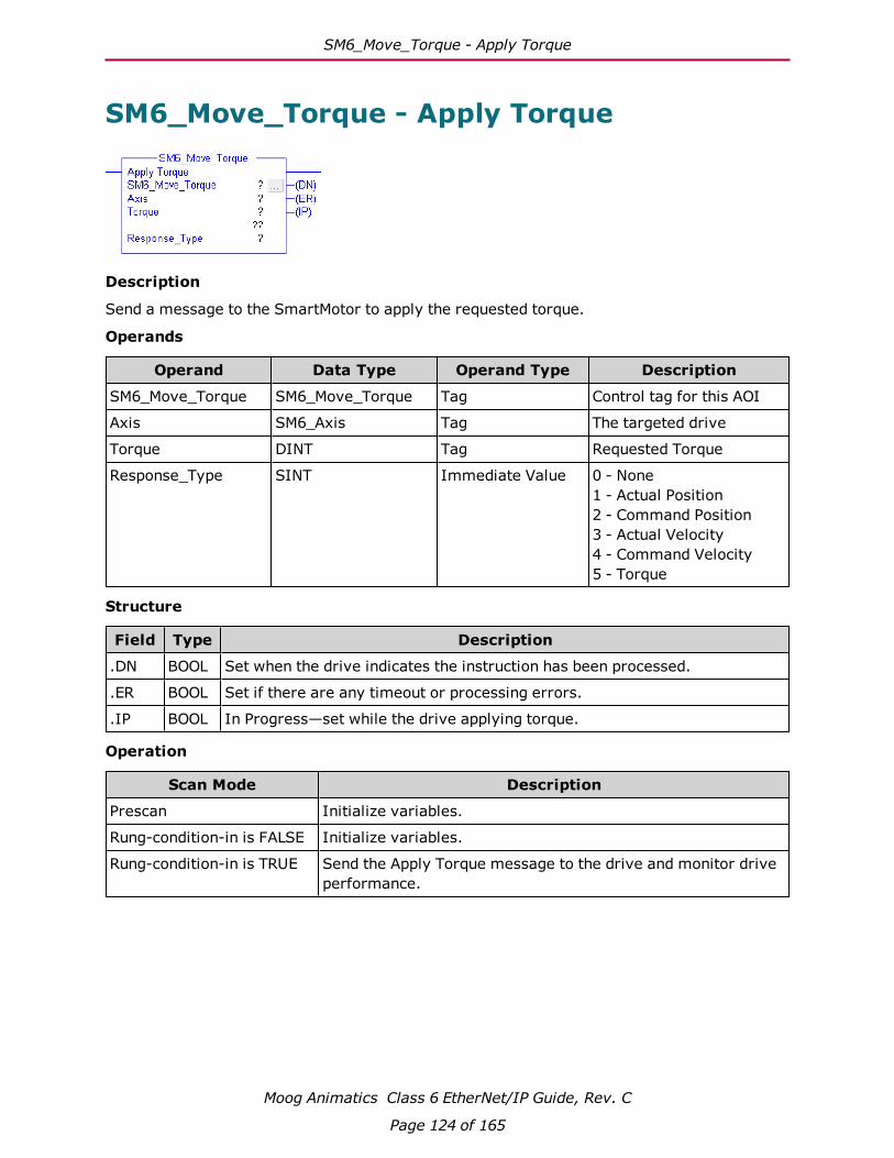
SM6_Move_Torque - Apply Torque
SM6_Move_Torque - Apply Torque
Description
Send a message to the SmartMotor to apply the requested torque.
Operands
Operand Data Type Operand Type Description
SM6_Move_Torque SM6_Move_Torque Tag Control tag for this AOI
Axis SM6_Axis Tag The targeted drive
Torque DINT Tag Requested Torque
Response_Type SINT Immediate Value 0 - None1 - Actual Position2 - Command Position3 - Actual Velocity4 - Command Velocity5 - Torque
Structure
Field Type Description
.DN BOOL Set when the drive indicates the instruction has been processed.
.ER BOOL Set if there are any timeout or processing errors.
.IP BOOL In Progress—set while the drive applying torque.
Operation
Scan Mode Description
Prescan Initialize variables.
Rung-condition-in is FALSE Initialize variables.
Rung-condition-in is TRUE Send the Apply Torque message to the drive and monitor drive performance.
Moog Animatics Class 6 EtherNet/IP Guide, Rev. C
Page 124 of 165
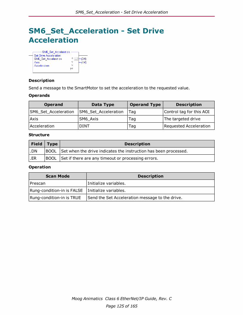
SM6_Set_Acceleration - Set Drive Acceleration
SM6_Set_Acceleration - Set Drive Acceleration
Description
Send a message to the SmartMotor to set the acceleration to the requested value.
Operands
Operand Data Type Operand Type Description
SM6_Set_Acceleration SM6_Set_Acceleration Tag Control tag for this AOI
Axis SM6_Axis Tag The targeted drive
Acceleration DINT Tag Requested Acceleration
Structure
Field Type Description
.DN BOOL Set when the drive indicates the instruction has been processed.
.ER BOOL Set if there are any timeout or processing errors.
Operation
Scan Mode Description
Prescan Initialize variables.
Rung-condition-in is FALSE Initialize variables.
Rung-condition-in is TRUE Send the Set Acceleration message to the drive.
Moog Animatics Class 6 EtherNet/IP Guide, Rev. C
Page 125 of 165
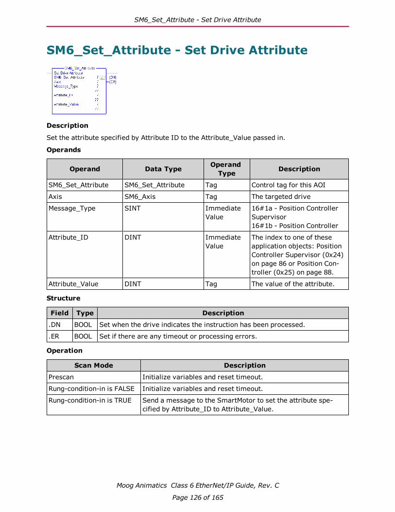
SM6_Set_Attribute - Set Drive Attribute
SM6_Set_Attribute - Set Drive Attribute
Description
Set the attribute specified by Attribute ID to the Attribute_Value passed in.
Operands
Operand Data Type Operand Type Description
SM6_Set_Attribute SM6_Set_Attribute Tag Control tag for this AOI
Axis SM6_Axis Tag The targeted drive
Message_Type SINT Immediate Value
16#1a - Position Controller Supervisor16#1b - Position Controller
Attribute_ID DINT Immediate Value
The index to one of these application objects: Position Controller Supervisor (0x24) on page 86 or Position Con-troller (0x25) on page 88.
Attribute_Value DINT Tag The value of the attribute.
Structure
Field Type Description
.DN BOOL Set when the drive indicates the instruction has been processed.
.ER BOOL Set if there are any timeout or processing errors.
Operation
Scan Mode Description
Prescan Initialize variables and reset timeout.
Rung-condition-in is FALSE Initialize variables and reset timeout.
Rung-condition-in is TRUE Send a message to the SmartMotor to set the attribute spe-cified by Attribute_ID to Attribute_Value.
Moog Animatics Class 6 EtherNet/IP Guide, Rev. C
Page 126 of 165

SM6_Set_Deceleration - Set Drive Deceleration
SM6_Set_Deceleration - Set Drive Deceleration
Description
Send a message to the SmartMotor to set the Deceleration to the requested value.
Operands
Operand Data Type Operand Type Description
SM6_Set_Deceleration SM6_Set_Deceleration Tag Control tag for this AOI
Axis SM6_Axis Tag The targeted drive
Acceleration DINT Tag Requested Acceleration
Structure
Field Type Description
.DN BOOL Set when the drive indicates the instruction has been processed.
.ER BOOL Set if there are any timeout or processing errors.
Operation
Scan Mode Description
Prescan Initialize variables.
Rung-condition-in is FALSE Initialize variables.
Rung-condition-in is TRUE Send the Set Deceleration message to the drive.
Moog Animatics Class 6 EtherNet/IP Guide, Rev. C
Page 127 of 165

SM6_Set_Mode - Set Drive Mode
SM6_Set_Mode - Set Drive Mode
Description
Send a message to the SmartMotor to set the Drive Mode to the requested value.
Operands
Operand Data Type Operand Type Description
SM6_Set_Mode SM6_Set_Mode Tag Control tag for this AOI
Axis SM6_Axis Tag The targeted drive
Mode SINT Tag Requested Drive Mode0 = Position1 = Velocity2 = Torque
Structure
Field Type Description
.DN BOOL Set when the drive indicates the instruction has been processed.
.ER BOOL Set if there are any timeout or processing errors.
Operation
Scan Mode Description
Prescan Initialize variables.
Rung-condition-in is FALSE Initialize variables.
Rung-condition-in is TRUE Send the Set Mode message to the drive.
Moog Animatics Class 6 EtherNet/IP Guide, Rev. C
Page 128 of 165
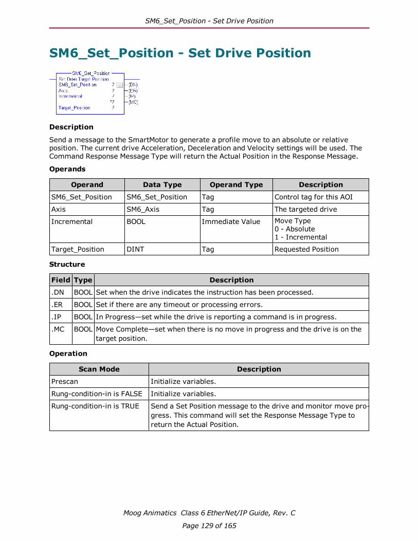
SM6_Set_Position - Set Drive Position
SM6_Set_Position - Set Drive Position
Description
Send a message to the SmartMotor to generate a profile move to an absolute or relative position. The current drive Acceleration, Deceleration and Velocity settings will be used. The Command Response Message Type will return the Actual Position in the Response Message.
Operands
Operand Data Type Operand Type Description
SM6_Set_Position SM6_Set_Position Tag Control tag for this AOI
Axis SM6_Axis Tag The targeted drive
Incremental BOOL Immediate Value Move Type0 - Absolute 1 - Incremental
Target_Position DINT Tag Requested Position
Structure
Field Type Description
.DN BOOL Set when the drive indicates the instruction has been processed.
.ER BOOL Set if there are any timeout or processing errors.
.IP BOOL In Progress—set while the drive is reporting a command is in progress.
.MC BOOL Move Complete—set when there is no move in progress and the drive is on the target position.
Operation
Scan Mode Description
Prescan Initialize variables.
Rung-condition-in is FALSE Initialize variables.
Rung-condition-in is TRUE Send a Set Position message to the drive and monitor move pro-gress. This command will set the Response Message Type to return the Actual Position.
Moog Animatics Class 6 EtherNet/IP Guide, Rev. C
Page 129 of 165

SM6_Set_Variable_u - Set Drive Variable "u"
SM6_Set_Variable_u - Set Drive Variable "u"
Description
Send a message to the SmartMotor to set the drive variable "u" to the requested value.
Operands
Operand Data Type Operand Type Description
SM6_Set_Variable_u SM6_Set_Variable_u Tag Control tag for this AOI
Axis SM6_Axis Tag The targeted drive
Value DINT Immediate value New variable value
Structure
Field Type Description
.DN BOOL Set when the drive indicates the instruction has been processed.
.ER BOOL Set if there are any timeout or processing errors.
Operation
Scan Mode Description
Prescan Initialize variables.
Rung-condition-in is FALSE Initialize variables.
Rung-condition-in is TRUE Send a message to the drive to set the drive variable "u" to the requested value.
Moog Animatics Class 6 EtherNet/IP Guide, Rev. C
Page 130 of 165

SM6_Set_Velocity - Set Drive Target Velocity
SM6_Set_Velocity - Set Drive Target Velocity
Description
Send a message to the SmartMotor to generate a profile move to a requested Velocity. The current drive Acceleration and Deceleration settings will be used. The Response Message Type to return the Actual Velocity.
Operands
Operand Data Type Operand Type Description
SM6_Set_Velocity SM6_Set_Velocity Tag Control tag for this AOI
Axis SM6_Axis Tag The targeted drive
Direction BOOL Immediate Value Requested Direction0=Reverse1=Forward
Target_Velocity DINT Tag Requested Velocity
Structure
Field Type Description
.DN BOOL Set when the drive indicates the instruction has been processed.
.ER BOOL Set if there are any timeout or processing errors.
.IP BOOL In Progress—set while the drive is reporting a command is in progress.
Operation
Scan Mode Description
Prescan Initialize variables.
Rung-condition-in is FALSE Initialize variables.
Rung-condition-in is TRUE Send a Set Velocity message to the drive and monitor move pro-gress. This command will set the Response Message Type to return the Actual Velocity.
Moog Animatics Class 6 EtherNet/IP Guide, Rev. C
Page 131 of 165

SM6_Stop_Hard - Perform a Hard Stop
SM6_Stop_Hard - Perform a Hard Stop
Description
Set the Hard Stop flag in the Command Control byte. This will cause the drive to stop with no deceleration.
Operands
Operand Data Type Operand Type Description
SM6_Stop_Hard SM6_Stop_Hard Tag Control tag for this AOI
Axis SM6_Axis Tag The targeted drive
Structure
Field Type Description
.DN BOOL Set when the drive indicates the instruction has been processed.
.ER BOOL Set if there are any timeout or processing errors.
.IP BOOL In Progress—set while the drive is reporting a command is in progress.
Operation
Scan Mode Description
Prescan Initialize variables.
Rung-condition-in is FALSE Initialize variables.
Rung-condition-in is TRUE Set the Hard Stop flag in the Command Control byte.
Moog Animatics Class 6 EtherNet/IP Guide, Rev. C
Page 132 of 165

SM6_Stop_Smooth - Perform a Smooth Stop
SM6_Stop_Smooth - Perform a Smooth Stop
Description
Set the Smooth Stop flag in the Command Control byte. This will cause the drive to decelerate to a stop.
Operands
Operand Data Type Operand Type Description
SM6_Stop_Smooth SM6_Stop_Smooth Tag Control tag for this AOI
Axis SM6_Axis Tag The targeted drive
Structure
Field Type Description
.DN BOOL Set when the drive indicates the instruction has been processed.
.ER BOOL Set if there are any timeout or processing errors.
.IP BOOL In Progress—set while the drive is reporting a command is in progress.
Operation
Scan Mode Description
Prescan Initialize variables.
Rung-condition-in is FALSE Initialize variables.
Rung-condition-in is TRUE Set the Smooth Stop bit in the Command Control byte.
Moog Animatics Class 6 EtherNet/IP Guide, Rev. C
Page 133 of 165

Adding AOI Support - Allen Bradley PLC
Adding AOI Support - Allen Bradley PLCThis chapter contains procedures that describe the steps for adding Add on Instruction (AOI) SmartMotor support to a new project using Allen Bradley Studio 5000 Logix Designer software.
Extracting the SmartMotor Support files 135
Adding a SmartMotor Module 136
Importing the UDTs 143
Importing the AOIs 147
SmartMotor AOI Example 151
Moog Animatics Class 6 EtherNet/IP Guide, Rev. C
Page 134 of 165
Extracting the SmartMotor Support files
Extracting the SmartMotor Support filesThe support files for the SmartMotor are in a file named SM6_Support_Files.zip. Extract all of the files to a location accessible to the Studio 5000 Logix Designer software. The extracted folder contains three sub-folders:
Sub-folder Description
SM6_Examples Sample Studio 5000 Logix Designer project files
SM6_AOIs The SmartMotor Add-On Instruction library
SM6_UDT The SmartMotor Add-On Instruction data type library
Moog Animatics Class 6 EtherNet/IP Guide, Rev. C
Page 135 of 165

Adding a SmartMotor Module
Adding a SmartMotor ModuleThis section describes the procedure for adding a SmartMotor module to the Ethernet port.
1. Start the Studio 5000 Logix Designer software and open a new project. See that soft-ware's help file for details.
2. In the I/O Configuration folder, right-click the Ethernet port and then click New Module.
Adding a new Ethernet module
Moog Animatics Class 6 EtherNet/IP Guide, Rev. C
Page 136 of 165

Adding a SmartMotor Module
3. In the Select Module Type dialog, select the "Class6 - SM6-M" item and then click Create. The module is created and the New Module dialog opens.
NOTE: Select the Close on Create option at the bottom of the dialog.
Select Module Type
Moog Animatics Class 6 EtherNet/IP Guide, Rev. C
Page 137 of 165

Adding a SmartMotor Module
4. On the New Module - General Tab:
a. Type the Name, Description and Ethernet Address in the corresponding boxes.
b. Click Change to configure the Module Definition. The Module Definition dialog opens.
New Module Configuration - General Tab
Moog Animatics Class 6 EtherNet/IP Guide, Rev. C
Page 138 of 165
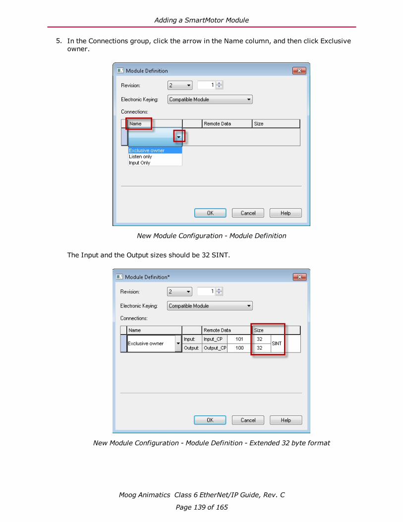
Adding a SmartMotor Module
5. In the Connections group, click the arrow in the Name column, and then click Exclusive owner.
New Module Configuration - Module Definition
The Input and the Output sizes should be 32 SINT.
New Module Configuration - Module Definition - Extended 32 byte format
Moog Animatics Class 6 EtherNet/IP Guide, Rev. C
Page 139 of 165

Adding a SmartMotor Module
To change the connection to support only the Standard 8-byte Position Controller messaging, change the Input and Output size to "8 SINT" by selecting each size and changing the value from 32 to 8.
New Module Configuration - Module Definition - Standard 8-byte format
Click OK. The dialog box closes. If the following prompt is displayed, click Yes.
The Requested Packet Interval (RPI) can be changed from the New Module Configuration - Connection tab. The default value is 20 ms.
Moog Animatics Class 6 EtherNet/IP Guide, Rev. C
Page 140 of 165
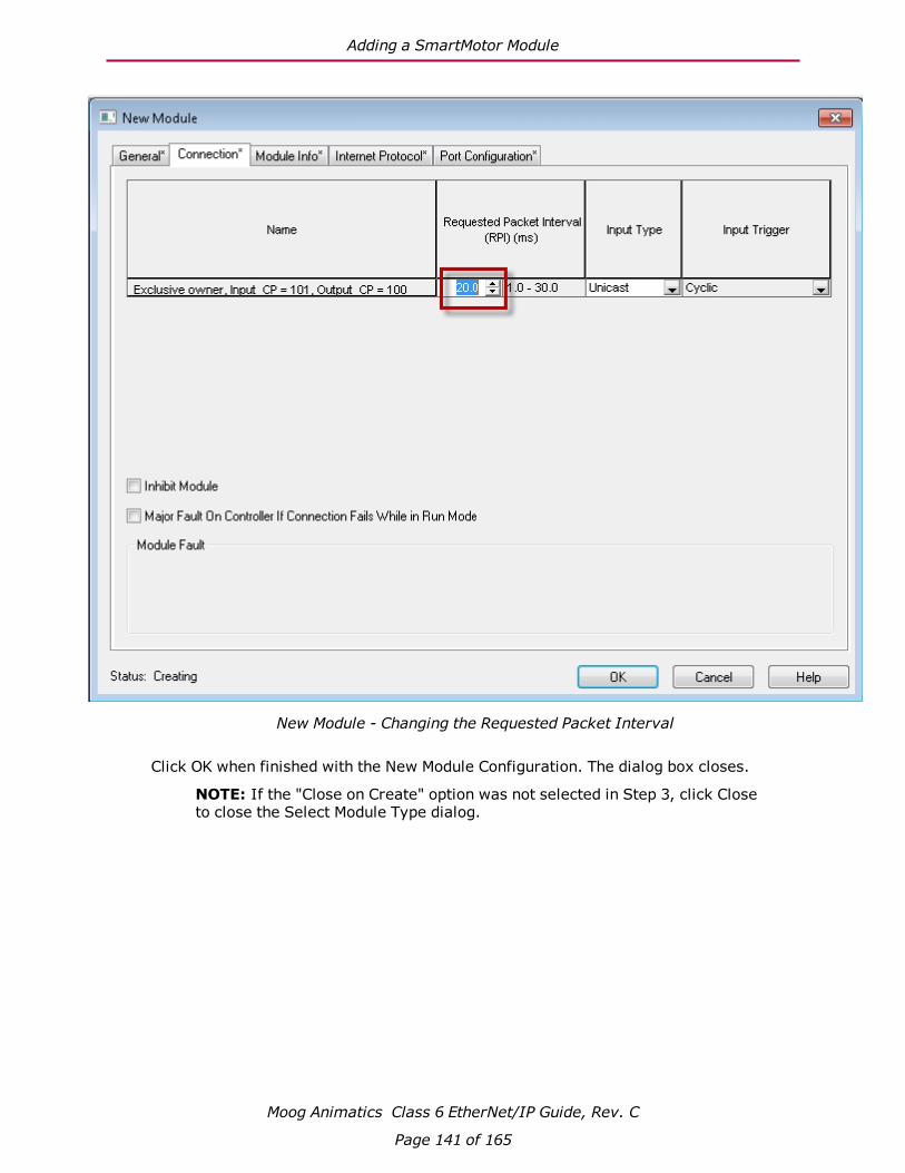
Adding a SmartMotor Module
New Module - Changing the Requested Packet Interval
Click OK when finished with the New Module Configuration. The dialog box closes.
NOTE: If the "Close on Create" option was not selected in Step 3, click Close to close the Select Module Type dialog.
Moog Animatics Class 6 EtherNet/IP Guide, Rev. C
Page 141 of 165

Adding a SmartMotor Module
6. The SmartMotor should now be configured. It is displayed in the Controller Organizer's I/O Configuration folder, Ethernet port item.
NOTE: When the SmartMotor is added, two Module-Defined data types will also be added that match the module configuration.
Controller Organizer with SmartMotor and Module-Defined items added
Moog Animatics Class 6 EtherNet/IP Guide, Rev. C
Page 142 of 165

Importing the UDTs
Importing the UDTsThis section describes the procedure for importing the User-Defined Data Types (UDTs) used in the Add-On Instructions (AOIs).
NOTE: The UDTs should be imported before the AOIs.
1. In the Controller Organizer, right-click the Data Types > User-Defined folder and select Import Data Type.
Importing a User Data Type
The Import Data Type dialog opens.
Moog Animatics Class 6 EtherNet/IP Guide, Rev. C
Page 143 of 165

Importing the UDTs
2. In the Import Data Type dialog, browse to the location of the UDT library.
Selecting a UDT file
3. Select the next UDT file to be imported, and then click Import. The Import Configuration dialog opens.
NOTE: The UDT file SM6_Axis.L5X should be imported last.
Moog Animatics Class 6 EtherNet/IP Guide, Rev. C
Page 144 of 165

Importing the UDTs
4. On the Import Configuration dialog, click OK.
Import Configuration - Complete UDT File Import
Moog Animatics Class 6 EtherNet/IP Guide, Rev. C
Page 145 of 165
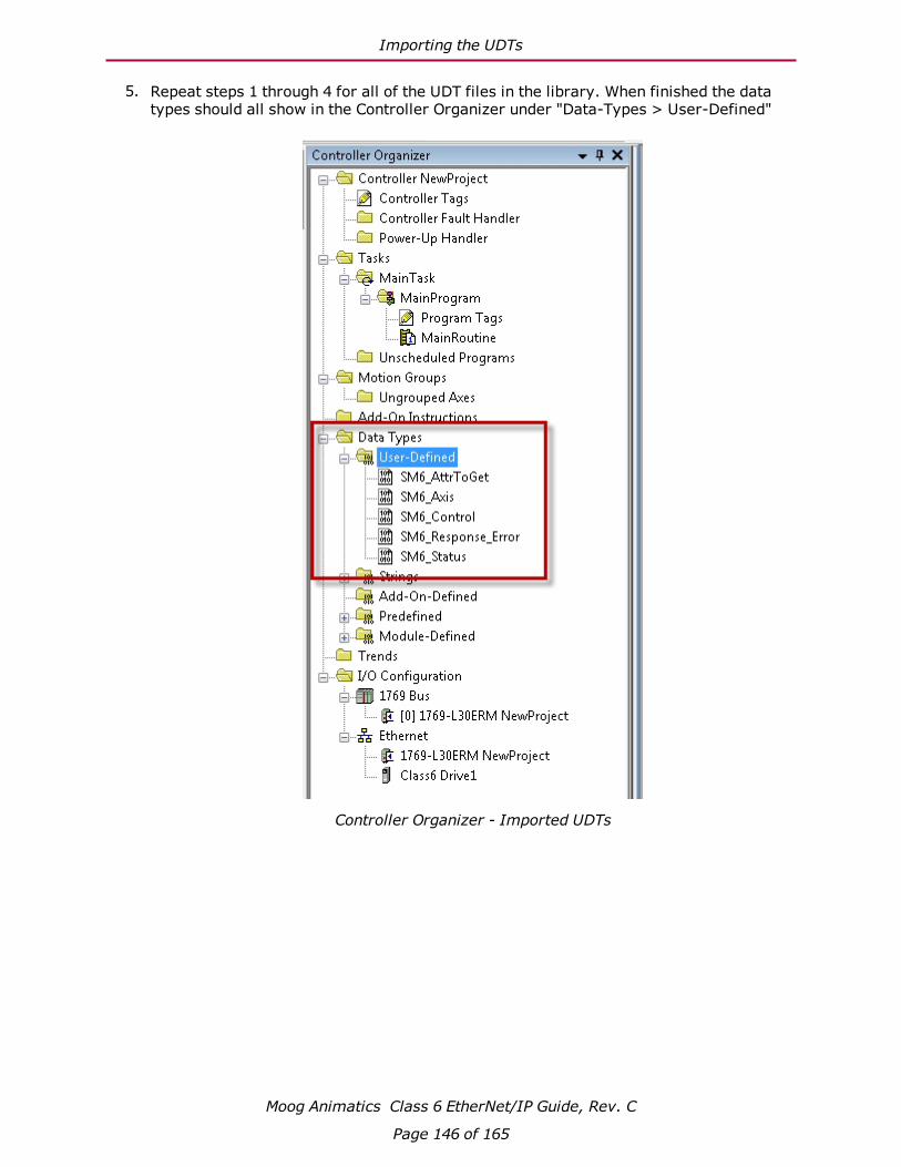
Importing the UDTs
5. Repeat steps 1 through 4 for all of the UDT files in the library. When finished the data types should all show in the Controller Organizer under "Data-Types > User-Defined"
Controller Organizer - Imported UDTs
Moog Animatics Class 6 EtherNet/IP Guide, Rev. C
Page 146 of 165

Importing the AOIs
Importing the AOIsThis section describes the procedure for importing the Add-On Instructions (AOIs).
1. In the Controller Organizer, right-click the Add-On Instructions folder and select Import Add-On Instruction.
Importing Add-On Instructions
The Import Add-On Instruction dialog opens.
Moog Animatics Class 6 EtherNet/IP Guide, Rev. C
Page 147 of 165

Importing the AOIs
2. In the Import Add-On Instruction dialog, browse to the location of the AOI library.
NOTE: Import the file SM6_Set_Attribute.L5X first; it is used for some of the other AOIs.
SM6_Set_Attribute.L5X AOI File Import
3. Select the AOI file to be imported, and then click Import. The Import Configuration dia-log opens.
Moog Animatics Class 6 EtherNet/IP Guide, Rev. C
Page 148 of 165
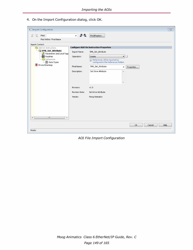
Importing the AOIs
4. On the Import Configuration dialog, click OK.
AOI File Import Configuration
Moog Animatics Class 6 EtherNet/IP Guide, Rev. C
Page 149 of 165

Importing the AOIs
5. Repeat steps 1 through 4 for all AOI files in the library. When finished, the data types should be listed in the Controller Organizer under the Add-On Instructions folder.
NOTE: It is not required to import all AOI files; however, an AOI must be imported before it can be used. If an AOI references an AOI file that has not yet been imported, the Studio 5000 Logix Designer software will automatically import it.
Controller Organizer - Imported AOI Files
Moog Animatics Class 6 EtherNet/IP Guide, Rev. C
Page 150 of 165

SmartMotor AOI Example
SmartMotor AOI ExampleThis section provides an example of using the SmartMotor Add-On Instructions (AOIs) in a ladder logic program.
The AOI distribution has three example projects in the sub-folder: ...\SM6_Support_Files\SM6_Examples.
l NewProject.ACD: The program created through the following procedure.
l Example_2Motor.ACD: A program that moves two motors back and forth, first one motor moves then the other.
l Example_2Motor_Parallel.ACD: A Program that moves two motors back and forth simultaneously.
To create the program:
1. In the Controller Organizer, right-click the Main Task > MainRoutine folder and select Open.
Open the Main Program Routine
Moog Animatics Class 6 EtherNet/IP Guide, Rev. C
Page 151 of 165

SmartMotor AOI Example
An empty MainProgram - MainRoutine ladder logic form opens.
MainRoutine Ladder Logic Form
Moog Animatics Class 6 EtherNet/IP Guide, Rev. C
Page 152 of 165

SmartMotor AOI Example
2. Right-click on Rung 0 and select Add Ladder Element.
The Add Ladder Element opens.
Moog Animatics Class 6 EtherNet/IP Guide, Rev. C
Page 153 of 165
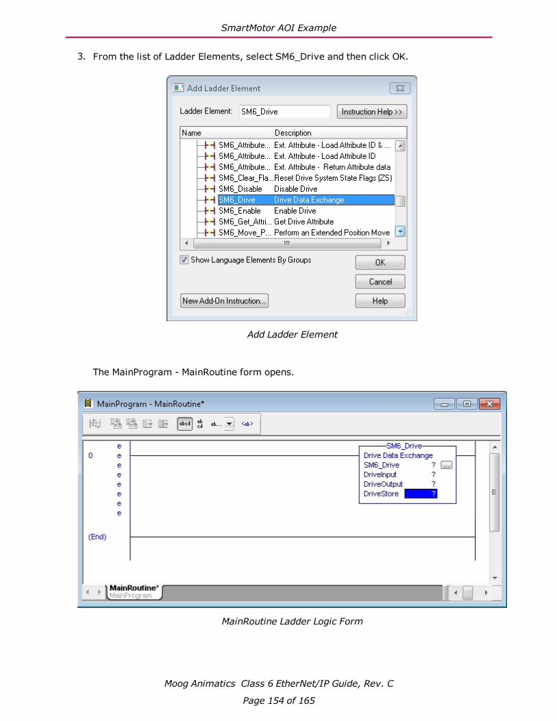
SmartMotor AOI Example
3. From the list of Ladder Elements, select SM6_Drive and then click OK.
Add Ladder Element
The MainProgram - MainRoutine form opens.
MainRoutine Ladder Logic Form
Moog Animatics Class 6 EtherNet/IP Guide, Rev. C
Page 154 of 165

SmartMotor AOI Example
4. In SM6_Drive block SM6-Drive parameter value field, right-click on the "?" and select New Tag.
Fill in the Name and Description boxes of the New tag and click Create.
New Tag - Name and Description Boxes
Moog Animatics Class 6 EtherNet/IP Guide, Rev. C
Page 155 of 165

SmartMotor AOI Example
5. In SM6_Drive block SM6-DriveStore parameter value field, right-click on the "?" and select New Tag.
Fill in the Name and Description boxes of the New tag and click Create.
New Tag - Name and Description Boxes
Moog Animatics Class 6 EtherNet/IP Guide, Rev. C
Page 156 of 165

SmartMotor AOI Example
6. In the SM6_Drive block, DriveInput parameter, double-click the "?" in the value field and then click the arrow.
In the tag list, double-click Drive1:I to select the Input Connection variable.
Drive 1:I Input Connection Variable
Moog Animatics Class 6 EtherNet/IP Guide, Rev. C
Page 157 of 165

SmartMotor AOI Example
7. In the SM6_Drive block, DriveOutput parameter, double-click "?" and click the arrow.
In the tag list, double-click Drive1:O to select the Output Connection variable.
Drive 1:O Output Connection Variable
Moog Animatics Class 6 EtherNet/IP Guide, Rev. C
Page 158 of 165

SmartMotor AOI Example
The MainRoutine should look as follows:
Completed MainRoutine
The following figure shows a complete program using the AOIs to move a drive back and forth between positions 100000 and -100000.
NOTE: The project for this program can be imported from the AOI support files (...\SM6_Support_Files\SM6_Examples\NewProject.ACD).
Moog Animatics Class 6 EtherNet/IP Guide, Rev. C
Page 159 of 165

SmartMotor AOI Example
Moog Animatics Class 6 EtherNet/IP Guide, Rev. C
Page 160 of 165

Troubleshooting
TroubleshootingThe following table provides troubleshooting information for solving SmartMotor problems that may be encountered when using CANopen. For additional support resources, see the Moog Animatics Support page at:
http://www.animatics.com/support.html
Issue Cause SolutionEtherNet/IP Communication IssuesMaster device does not recognize motor.
Motor not powered. Check Drive Status LED. If LED is not lit, check wiring.
Disconnected or miswired connector, or broken wiring between motors.
Check that connector is correctly wired and connected to motor. For details, see Connections, Wiring and Status LEDs on page 24.
Wrong node ID (address) Set address and then reboot motor. For details, see Network Settings and Status Commands on page 36.
Wrong firmware Please consult Moog Animatics for the proper software version.
Network flooded with traffic.
Reduce the network to just the SmartMotor and try a simple move command without interference from other devices.
Solid red error LED. A warning or bus off condition has occurred.
A blinking red LED may indicate occasional issues from any of the causes listed above; a solid red LED indicates that these issues have occurred frequently, which causes the motor to stop communicating (bus off condition). In this case, the SmartMotor must be reset after fixing the cause of the problem.
Communication and Control IssuesMotor control power light does not illuminate.
Motor is equipped with the DE option.
To energize control power, apply 24-48 VDC to pin 15 and ground to pin 14.
Motor has routed drive power through drive-enable pins.
Ensure cabling is correct and drive power is not being delivered through the 15-pin connector.
Motor does not communicate with SMI.
Transmit, receive, or ground pins are not connected correctly.
Ensure that transmit, receive and ground are all connected properly to the host PC.
Motor program is stuck in a continuous loop or is disabling communications.
To prevent the program from running on power up, use the Communications Lockup Wizard located on the SMI software Communications menu.
Motor disconnects from SMI sporadically.
COM port buffer settings are too high.
Adjust the COM port buffer settings to their lowest values.
Moog Animatics Class 6 EtherNet/IP Guide, Rev. C
Page 161 of 165
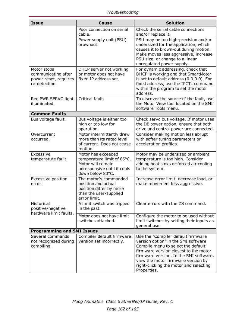
Troubleshooting
Issue Cause Solution
Poor connection on serial cable.
Check the serial cable connections and/or replace it.
Power supply unit (PSU) brownout.
PSU may be too high-precision and/or undersized for the application, which causes it to brown-out during motion. Make moves less aggressive, increase PSU size, or change to a linear unregulated power supply.
Motor stops communicating after power reset, requires re-detection.
DHCP server not working or motor does not have fixed IP address set.
For dynamic addressing, check that DHCP is working and that SmartMotor is set to default address (0.0.0.0). For fixed address, use the IPCTL command within the program to set the motor address.
Red PWR SERVO light illuminated.
Critical fault. To discover the source of the fault, use the Motor View tool located on the SMI software Tools menu.
Common FaultsBus voltage fault. Bus voltage is either too
high or too low for operation.
Check servo bus voltage. If motor uses the DE power option, ensure that both drive and control power are connected.
Overcurrent occurred.
Motor intermittently drew more than its rated level of current. Does not cease motion
Consider making motion less abrupt with softer tuning parameters or acceleration profiles.
Excessive temperature fault.
Motor has exceeded temperature limit of 85°C. Motor will remain unresponsive until it cools down below 80°C.
Motor may be undersized or ambient temperature is too high. Consider adding heat sinks or forced air cooling to the system.
Excessive position error.
The motor's commanded position and actual position differ by more than the user-supplied error limit.
Increase error limit, decrease load, or make movement less aggressive.
Historical positive/negative hardware limit faults.
A limit switch was tripped in the past.
Clear errors with the ZS command.
Motor does not have limit switches attached.
Configure the motor to be used without limit switches by setting their inputs as general use.
Programming and SMI IssuesSeveral commands not recognized during compiling.
Compiler default firmware version set incorrectly.
Use the "Compiler default firmware version option" in the SMI software Compile menu to select the default firmware version closest to the motor firmware version. In the SMI software, view the motor firmware version by right-clicking the motor and selecting Properties.
Moog Animatics Class 6 EtherNet/IP Guide, Rev. C
Page 162 of 165

Reference Documents
Reference DocumentsThis section lists the documents that were referenced for this guide.
ODVA SpecificationsThe following ODVA specifications were referenced for this guide:
l THE CIP NETWORKS LIBRARY, Volume 1: Common Industrial Protocol (CIP™), Edition 3.16, April 2014.
l THE CIP NETWORKS LIBRARY, Volume 2: EtherNet/IP Adaptation of CIP, Edition 1.17, April 2014.
These volumes comprise The EtherNet/IP™ Specification, which must be purchased using the order form on the ODVA.org website at:
https://secure.odva.org/forms/spec-vendor-id-order-form.htm
ODVA LibrariesThe following ODVA libraries were referenced for introductory topics:
l The CIP Technology Library
l The EtherNet/IP Library
These ODVA libraries can be accessed directly on the ODVA.org website at:
http://www.odva.org/Publication-Download
Moog Animatics Class 6 EtherNet/IP Guide, Rev. C
Page 163 of 165


PN: SC80100010-001Rev. C