monitoring for fine particulate matter - rand.org new federal reference method (frm) for measuring...
TRANSCRIPT

Monitoring forFine Particulate
Matter
Elisa Eiseman
Critical Technologies Institute
R

The research described in this report was conducted by RAND’sCritical Technologies Institute.
RAND is a nonprofit institution that helps improve policy anddecisionmaking through research and analysis. RAND’s publicationsdo not necessarily reflect the opinions or policies of its researchsponsors.
© Copyright 1998 RAND
All rights reserved. No part of this book may be reproduced in anyform by any electronic or mechanical means (includingphotocopying, recording, or information storage and retrieval)without permission in writing from RAND.
Cover design: Elisa EisemanPublished 1998 by RAND
1700 Main Street, P.O. Box 2138, Santa Monica, CA 90407-21381333 H St., N.W., Washington, D.C. 20005-4707
RAND URL: http://www.rand.org/To order RAND documents or to obtain additional information,
contact Distribution Services: Telephone: (310) 451-7002; Fax: (310) 451-6915; Internet: [email protected]
This document is available on the World Wide Web athttp://www.rand.org/publications/MR/MR974
ISBN: 0-8330-2618-6

iii
PREFACE
In accordance with the Clean Air Act, the United States Environmen-tal Protection Agency (EPA) has reviewed the National Ambient AirQuality Standards (NAAQS) for particulate matter (PM) and set newstandards for fine particulate matter with a diameter less than orequal to 2.5 μm (PM2.5). This document reviews the new Federal Ref-erence Method (FRM) developed by the EPA for monitoring PM2.5,which is a manual method that will be used to ensure national con-sistency in PM2.5 monitoring and compliance with the EPA’s newstandards for PM. This document also describes a number of com-mercially available monitoring technologies that could be utilized forcontinuous, real-time monitoring of PM2.5. This document shouldbe of interest to the EPA, policymakers, and individuals who need toconsider the feasibility of using available monitoring technology forimplementing and complying with the updated NAAQS for PM2.5. Itmay also be of interest to national, state and local regulators, who areprimarily responsible for ensuring attainment and maintenance ofthe EPA’s ambient air quality standards. The regulated communitymay also find it helpful to have information about monitoring tech-nologies for PM2.5.
The author is an American Association for the Advancement ofScience (AAAS) Science and Engineering Fellow at RAND’s CriticalTechnologies Institute (CTI). The author’s research for this docu-ment was sponsored by the White House Office of Science andTechnology Policy through CTI.
CTI was created in 1991 by an act of Congress. It is a federally fundedresearch and development center sponsored by the National ScienceFoundation and managed by RAND, a nonprofit corporation created

iv Monitoring for Fine Particulate Matter
for the purpose of improving public policy. CTI’s mission is to helpimprove public policy by conducting objective, independentresearch and analysis on policy issues that involve science and tech-nology to
• Support the Office of Science and Technology Policy and otherExecutive Branch agencies, offices and councils,
• Help science and technology decisionmakers understand thelikely consequences of their decisions and choose among alter-native policies, and
• Improve understanding in both the public and private sectors ofthe ways in which science and technology can better servenational objectives.
CTI research focuses on problems of science and technology policythat involve multiple agencies. In carrying out its mission, CTI con-sults broadly with representatives from private industry, institutionsof higher education, and other nonprofit institutions.
Inquiries regarding CTI or this document may be directed to:
Bruce DonDirector, Critical Technologies InstituteRAND1333 H St., N.W.Washington, D.C. 20005Phone: (202) 296-5000Web: http://www.rand.org/centers/cti/Email: [email protected]
v
CONTENTS
Preface .......................................... iii
Figures .......................................... vii
Summary ........................................ ix
Acknowledgments.................................. xi
Glossary ......................................... xiii
Chapter One INTRODUCTION ............................... 1 Definition of Particulate Matter ..................... 2 EPA’s Revised Particulate Matter Standards ............. 2
Chapter Two PM2.5 MONITORING ............................. 5 Federal Reference Method for PM2.5 .................. 6 Issues Regarding the Use of the PM2.5 Federal Reference
Method (FRM) .............................. 7 Time to Results................................ 7 Accuracy and Precision ......................... 8 Source Attribution ............................. 10
Continuous PM2.5 Monitors ........................ 11 Issues Regarding the Use of Continuous PM2.5 Monitors.... 12
Inferred Mass Measurements...................... 12 Particle Sizing ................................ 14 Chemical Composition ......................... 14

vi Monitoring for Fine Particulate Matter
Chapter Three CONCLUSIONS ................................ 17
Appendix A AIR MONITORING TECHNOLOGIES FOR PARTICULATE MATTER ...................................... 19 Federal Reference Method for Fine Particulate Matter (FRM
PM2.5) Sampler.............................. 19 Opacity Monitors ............................... 21 Light-Scattering Technologies ...................... 23 Beta Gauge .................................... 26 Acoustic-Energy Monitoring ....................... 28 Tapered Element Oscillating Microbalance (TEOM)....... 29 Triboelectric Technology.......................... 31
Appendix B EXAMPLES OF AIR MONITORING TECHNOLOGIES FOR PARTICULATE MATTER........................... 33 Aethalometer™................................. 33 Continuous Particulate Monitor (CPM)................ 36 Three-Color Integrating Nephelometer with Size-Selective
Inlet ..................................... 38 Light Detection and Ranging (Lidar) .................. 40
References ....................................... 43

vii
FIGURES
1. Sampling Time Line for the FRM ................ 82. Sources of Error ............................ 93. PM Monitors............................... 13


ix
SUMMARY
Particulate matter (PM), which includes dust, dirt, smoke, soot, andliquid droplets, comes from a variety of natural and anthropogenicsources and is a mixture of many pollutants made up of several dif-ferent chemical species. Recent evidence about health effects andthe fundamental physical and chemical differences between fine PM(particles 2.5 μm in diameter or smaller) and coarse PM (particles 2.5to 10 μm in diameter) prompted the EPA to consider separate stan-dards for fine and coarse PM. After a lengthy review of the NAAQSfor PM, the EPA set new standards for fine particulate matter with adiameter less than or equal to 2.5 μm (PM2.5). In addition to revisingthe monitoring requirements for coarse PM (PM10), these new stan-dards also established a new FRM for measuring PM2.5, new criteriafor placement of monitors, new schedules for data collection, andnew procedures for ensuring the quality of PM data.
PM monitoring is necessary to provide air quality data to local, state,and national regulatory programs for determining whether an areahas attained the new NAAQS. The FRM for PM2.5 was developed toassure compliance with the new standards for PM and to ensurenational consistency in PM2.5 monitoring. However, the FRM is amanual method that is not set up for continuous sampling. There-fore, a need also exists for the development of continuous monitor-ing technologies for determining PM mass. Several state-of-the-arttechnologies are commercially available for automated, continuousmonitoring of PM mass, including opacity monitors, light-scatteringtechnologies, beta gauges, acoustic-energy monitoring, tapered-element oscillating microbalance (TEOM), and triboelectric technol-

x Monitoring for Fine Particulate Matter
ogy. However, none of these methods has been approved by theEPA, since most of these devices do not directly measure mass.
Furthermore, measuring PM mass alone is not sufficient for sourceattribution, studies of health and welfare effects, and determinationof compliance with standards. It is also important to measurechemical composition. Therefore, a comprehensive approach to PMmonitoring requires a combination of analytical techniques to assessmass and chemical composition, and an integrated network of ambi-ent and source PM monitors. However, chemical analysis of PM iscostly and difficult, and existing technologies are not capable of con-tinuous sampling and monitoring for chemical composition.Therefore, the next generation of PM monitors should be multifunc-tional instruments capable of continuous, real-time monitoring ofboth PM mass and chemical composition. In addition, they will needto address several barriers to their use, including cost, complicatedcalibration and verification systems, and cumbersome installationand maintenance procedures.
xi
ACKNOWLEDGMENTS
The author would like to thank James Ball and Kevin Gashlin fromthe National Technology Transfer Center (NTTC); Kevin Doxey andRobert Boyd from the Department of Defense; Robert Holst from theStrategic Environmental Research and Development Program(SERDP); James E. Birdsall from the Electric Power Research Institute(EPRI); Ralph Robertson from RBM Consulting & Research Inc.;Lloyd Curie from the National Institute of Standards and Technology(NIST); Douglas Lawson, Technical Project Manager of the NorthernFront Range Air Quality Study (NFRAQS), from Colorado StateUniversity; and Janet Ranganathan from World Resources Institute(WRI) for providing information and critically reviewing this docu-ment. She would also like to thank Susan Resetar and Beth Lachmanfor their guidance and editorial help with this document. Originalartwork by Emer Ibarra, displayed on the EPA’s Air Quality GalleryWebsite (URL: http://www.epa.gov/oar/oaqps/gallery.html), wasthe inspiration for the cover design. Points of view or opinions statedin this document are those of the author and do not represent theposition or policy of RAND, the Office of Science and TechnologyPolicy, or the above contributors to this work.


xiii
GLOSSARY
AAS Atomic absorption spectrometry
AC Automated colorimetry
CEMS Continuous emissions monitoring systems
CPM Continuous Particulate Monitors
EPA United States Environmental Protection Agency
FRM Federal Reference Method
GC/MS Gas chromatography combined with mass spec-troscopy
gr/dscf Grains per dry standard cubic foot
HPLC High-performance liquid chromatography
IC Ion chromatography
INAA Instrumental neutron activation analysis
lidar Light detection and ranging
NAAQS National Ambient Air Quality Standards
NOx Nitrogen oxides
PIXE Particle-induced x-ray emission
PM Particulate matter
PM10 Particulate matter 10 μm in diameter or smaller
PM2.5 Particulate matter 2.5 μm in diameter or smaller

xiv Monitoring for Fine Particulate Matter
ppb Parts per billion
SO2 Sulfur dioxide
TEOM Tapered-element oscillating microbalance
TÜV German Technical Inspection Agency
VOC Volatile organic compounds
XRF X-ray fluorescence

1
Chapter One
INTRODUCTION
The Clean Air Act, passed by Congress in 1970, requires the U.S. En-vironmental Protection Agency (EPA) to review the air quality stan-dards periodically for six major air pollutants and incorporate thebest available science into these standards to protect the Americanpublic from the health hazards of air pollution [1].1 Recently, theEPA reviewed the current National Ambient Air Quality Standards(NAAQS) for particulate matter (soot) and on July 17, 1997, set newstandards for fine particulate matter (PM) with a diameter less thanor equal to 2.5 μm (PM2.5) [2].2 These new standards also establisheda new Federal Reference Method (FRM) for measuring fine particles,new criteria for placement of monitors, new schedules for datacollection, and new procedures for insuring the quality of PM data[3].
This report reviews the new NAAQS for PM and the new FRM fordetermining the mass of PM2.5. A number of commercially availablemonitoring technologies that could be utilized for continuous moni-toring of PM2.5 are also described. This report also provides a defini-tion of PM and outlines a number of issues inherent in using thesetechnologies for environmental compliance monitoring. Theappendixes provide detailed information on the applications, mech-anisms of action, and advantages of and barriers to commercializa-tion of specific alternative monitoring technologies.
______________1The six air pollutants Congress specified in the Clean Air Act are ozone, particulatematter, nitrogen dioxide, carbon dioxide, sulfur dioxide, and lead [1].2Concurrently, the EPA also reviewed the NAAQS for ground-level ozone (smog) andissued new air quality standards for ozone [4].

2 Monitoring for Fine Particulate Matter
DEFINITION OF PARTICULATE MATTER
Particulate matter (PM), which includes dust, dirt, smoke, soot, andliquid droplets, comes from a variety of natural and anthropogenicsources and is a mixture of many pollutants made up of several dif-ferent chemical species. Airborne PM can be divided into twoclasses, fine PM (particles 2.5 μm in diameter or smaller) and coarsePM (particles 2.5 to 10 μm in diameter), which differ not only in sizebut may also differ in source, chemical composition, physical prop-erties, and formation process [5].3 Fine PM (PM2.5) is derived mainlyfrom combustion material that has volatilized and then condensed,or from the condensation or transformation of emitted gases in theatmosphere, such as sulfur dioxide (SO2), nitrogen oxides (NOx) andvolatile organic compounds (VOC) [5]. Major sources of PM2.5 arefossil fuel combustion by electric utilities, industry, and motor vehi-cles; residential fireplaces and wood stoves; vegetation burning; andthe smelting or other processing of metals [5]. Examples of naturalbioaerosols suspended as PM2.5 include bacteria, viruses, and endo-toxins. Major components of PM2.5 are sulfate, strong acid, ammo-nium, nitrate, organic compounds, trace elements (including met-als), elemental carbon, and water [5]. Coarse PM is formed bycrushing, grinding, and abrasion of surfaces, which are then sus-pended by the wind or by anthropogenic activity [5]. Mining andagricultural activities are examples of anthropogenic sources ofcoarse PM [5]. Fugitive dust constitutes about 90 percent of esti-mated coarse PM [5]. Fungal spores, pollen, and plant and insectfragments are examples of natural bioaerosols suspended as coarsePM [5]. Therefore, since fine and coarse PM are derived from dis-tinctly different sources and have different chemical and physicalproperties, monitoring ambient levels of each would facilitate theplanning of effective control strategies.
EPA’S REVISED PARTICULATE MATTER STANDARDS
Recent evidence about health effects and the fundamental physicaland chemical differences between fine and coarse PM prompted the
______________3The terms fine and coarse originally applied to the two major atmospheric particledistributions, which overlap in the size ranges between 1 and 3μm in diameter[5].More recently, fine has come to be associated with PM2.5, and coarse often refers toparticles 2.5 to 10 μm in diameter (PM10–2.5) [5].

Introduction 3
EPA to consider separate standards for fine and coarse PM. Previ-ously, the NAAQS for PM required monitoring of particles 10 μm indiameter or smaller (PM10), with the annual average set at 50 μg/m3
and the 24-hour average set at 150 μg/m3 [6]. However, the NAAQShave been revised to include new standards for particles 2.5 μm orsmaller (PM2.5), with the annual average set at 15 μg/m3 and the 24-hour average set at 65 μg/m3 [6]. PM10 standards were also revised sothat larger, coarse particles will continue to be regulated [6].4 Thenew air quality standards were implemented to address the latestscientific information on the effects of PM2.5 on public health andwelfare.
Since the standards were last revised in 1987, numerous studies havebeen published on the health effects of PM [7]. New PM-related epi-demiological studies have suggested correlations between breathingparticles at levels below the previous PM standards and harmfulhealth effects [2, 7]. The PM-related health effects observed in theseepidemiological studies included premature mortality, aggravationof respiratory and cardiovascular symptoms and illness, changes inlung structure and function, and altered respiratory defense mecha-nisms [7]. In addition, children, asthmatics, and individuals withcardiovascular or pulmonary disease, especially the elderly, are morelikely to suffer severe health effects related to PM exposure [7]. Whileboth coarse and fine PM can produce health effects, the fine PM,which penetrates deeply and remains in the lungs, is more likely tobe linked to the kinds of effects observed in these epidemiologicalstudies [2]. The EPA predicts that the new PM standards, along withclean air programs already planned, would reduce premature deathsby an estimated 15,000 per year and reduce serious respiratoryproblems in children by approximately 250,000 cases per year [7].
Effects on public welfare associated with ambient airborne PMinclude visibility impairment, climate change, and materials damage.The major cause of visibility impairment is PM2.5, so reducing PM2.5
concentrations will improve visibility [5]. Particles suspended in theatmosphere also exert an impact on climate by increasing the reflec-
______________4The EPA retained the annual PM10 standard of 50μg/m3 and adjusted the 24-hourPM10 standard of 150μg/m3 by replacing the one-expected-exceedance form with a99th percentile form, averaged over 3 years [2, 6].

4 Monitoring for Fine Particulate Matter
tion of solar radiation from cloud-free portions of the atmosphereand by increasing the brightness and stability of clouds [5]. Damageto materials by PM exposure includes soiling of painted surfaces,fabrics, electronics, and works of art and corrosion of metals andother building materials by acid aerosols and salts [5].
5
Chapter Two
PM2.5 MONITORING
Monitoring is necessary to determine the quality of our nation’s airand to assess the progress of control strategies toward achievingambient air quality goals. Air quality samples are generally collectedfor one or more of the following purposes [8]:
• To judge when an area has attained and/or made progresstoward meeting ambient air quality standards.
• To activate emergency control procedures that prevent or alle-viate air pollution episodes.
• To observe pollution trends throughout the region, includingnon-urban areas.
• To provide a database for research evaluation of effects: deter-mination of health and welfare effects; urban, land-use, andtransportation planning; development and evaluation of abate-ment strategies; and development and validation of diffusionmodels.
• To provide a baseline for market-based approaches such asemissions trading.
Since regulation requires information, monitoring technologies thatprovide information on compliance with environmental regulationsare essential.
The main purpose of PM monitoring is to provide air quality data tolocal, state, and national regulatory programs for determiningwhether an area has attained the NAAQS. To assure compliance with

6 Monitoring for Fine Particulate Matter
the new standards for PM, the EPA has developed a new FRM forPM2.5. However, the FRM is a manual method designed to measurePM2.5 mass and is not set up for continuous sampling or composi-tional analysis. Therefore, a need also exists for the development ofcontinuous monitoring technologies for determining both PM massand chemical composition.
FEDERAL REFERENCE METHOD FOR PM2.5
To ensure national consistency in air pollution monitoring, a FRM isused for making comparisons to the standards. The FRM for deter-mining the mass of fine particulate matter having an aerodynamicdiameter less than or equal to 2.5 μm (PM2.5) is a manual methodthat provides a direct measurement of the mass of ambient PM2.5
over a 24-hour period [6]. Briefly, the FRM utilizes an electricallypowered air sampler to draw air at a constant rate through animpactor, which is a particle size separator, where suspended PM2.5
is separated for collection on a filter (for more information on theFRM air sampler, see Appendix A). The filter is then removed fromthe sampler, brought back to the laboratory, equilibrated, andweighed to determine the ambient mass concentration of PM2.5.This analysis is costly, time consuming, and laborious. The samplingapparatus alone costs approximately $7,000 per unit, and requiresextra full time employees for daily sampling, with additional opera-tion and maintenance costs. In addition, the new PM2.5 monitoringnetwork will eventually consist of approximately 1,500 sites, withdaily sampling required at over 300 of these sites and sampling everythird day required at the rest [9].1 To defray the costs of establishingthe PM2.5 monitoring network, Congress has appropriated $35.6 mil-lion for the State and Tribal Assistance Grant account to be dis-tributed as EPA grants for “particulate matter monitoring and datacollection” [10].
Over the long term, there is a need for PM monitoring technologiesthat are continuous and automatic and that provide real-time analy-sis. To ensure that new, improved monitoring technologies are
______________1The PM2.5 network will initially consist of a minimum of approximately 850 requiredPM2.5 monitoring sites, while the mature network is projected to consist of 1,500PM2.5 sites within three years [9].

PM2.5 Monitoring 7
incorporated into the monitoring network, three classes of equiva-lent methods are established in the specifications for the FRM [3, 6,9]. Class I equivalent methods include minor sampler modificationsto allow the automatic collection of sequential samples withoutintermediate operator service, permitting easier and more cost effi-cient sampling on a daily basis. Class II equivalent methods includeall other filter-based methods that produce a 24-hour measurement.Finally, Class III equivalent methods include both continuous orsemicontinuous methods that are based on designs and measure-ment principles different from the reference method. However,there may be significant problems in translating from the manualreference method to a continuous one. In addition, the guidelinesfor the FRM are so strict that they may dictate adherence to a singlemethod, thereby inhibiting innovation.
ISSUES REGARDING THE USE OF THE PM2.5 FEDERAL REF-ERENCE METHOD (FRM)
Time to Results
The standard operating procedure for the new PM2.5 FRM defines thetime line for sampling and analysis of ambient PM [6] (Figure 1).Briefly, the PM2.5 sample is collected for 23–25 hours. The filter mustbe retrieved from the sampler within 96 hours (4 days) of the end ofthe sample collection period. After retrieval from the sampler, thefilter containing the PM2.5 sample is transported to the laboratory,ideally within 24 hours, for conditioning and equilibration and sub-sequent weighing. The filter is equilibrated for a minimum of 24hours. The postsampling weighing occurs immediately after the fil-ter is conditioned. If the filter is retrieved for conditioning immedi-ately after the sampling period, the minimum time from the begin-ning of sample collection to the report of results would be 47 hours(approximately 2 days). The stipulation that the postsampling equi-libration and weighing be completed within 240 hours (10 days) givesa maximum of approximately 11 days from start to finish. Sinceacute PM exposures (exposures of less than 1 day to up to 5 days) areassociated with an increased daily mortality, usually occurring eitheron the same day or within one day after exposure [5], these time lagsbetween sample collection and measurement of PM2.5 mass would

8 Monitoring for Fine Particulate Matter
RANDMR974-1
Post-sampling weighing occurs immediately after conditioning
Sampling Retrieve filters from sampler
Transport toconditioningenvironment
Conditioning/equilibration
Maximum time from sampling to results:
Total time = 265 hours (~11 days)
25hours
120 hours(5 days)
24hours
96 hours(4 days)
Minimum time from sampling to results:
Immediately retrieve filters and transport to conditioning environment
Total time = 47 hours (~2 days)
23hours
24hours
Sampling Conditioning/equilibration
Post-sampling weighing occurs immediately after conditioning
Figure 1—Sampling Time Line for the FRM. The sampling time line for theFRM illustrates the minimum and maximum time from sampling to mea-surement of PM2.5 mass. Chemical analysis of PM2.5 composition wouldrequire additional time and is not depicted in this figure.
not provide the general public with timely warnings about episodicair pollution hazards. In addition, since the FRM uses a 24 hourbatch sample, it would be difficult to correlate data with meteorolog-ical events or other time-sensitive emission sources that may lastonly minutes to hours, such as when there are heavy traffic flows,increased industrial activities, and periods of high energy demand.
Accuracy and Precision
The EPA’s standard for PM2.5 requires high-quality data, with mini-mal imprecision and relative error. The EPA’s quality assurance goalfor PM2.5 measurements is defined as within ±15 percent [6]. How-ever, there is significant error associated with the PM2.5 FRM. For

PM2.5 Monitoring 9
example, substantial errors of 50 percent or more have beenobserved when using different measurement techniques; samplers ofdifferent design or manufacturer; or even identical systems of differ-ent age, cleanliness, or placement [5]. It is possible to obtain mea-surements with a precision close to 10 percent when using collocatedsamplers of identical design and cleanliness [5]. Therefore, the cali-bration of equivalent methods with the FRM may be quite difficultand will be of utmost importance to ensure consistency and compli-ance with national standards.
The errors in PM2.5 measurements may arise during sampling, trans-port of the sample to the laboratory, and/or at the laboratory (seeFigure 2). One of the main sources of sampling error is the loss of
RANDMR974-2
Sampler error
• Loss of semivolatile components
• Ambient temperature <–30˚C (–22˚F) or >45˚C (113˚F)
• Filter temperature >3˚C above ambient temperature
• Adverse weather conditions• Sampler malfunction• Sampler design • Sampler age and cleanliness• Sampler leakage• Flow rate and sampling time
Transport error
• Temperature >32˚C (90˚F)
• Humidity• Removal of filter from
sampler• Protective container
failure• Transportation time• Handling and storage
Laboratory error
• Conditioning/equilibration– Variations of mean
temperature from20-30˚C (68-73˚F) ± 2˚C
– Variations of mean humidity from30-40% ± 5%
– Time <24 hours• Pre- and post-sampling
filter weighing• Handling and storage
FRM
Laboratory
Figure 2—Sources of Error. The EPA’s precision goal for PM2.5 measure-ments is ±15 percent. However, collocated samplers have shown errors of≥50 percent due to sample, transport and/or laboratory error.

10 Monitoring for Fine Particulate Matter
semivolatile components, such as certain organics and nitrates,through evaporation and sublimation during variable temperatureand humidity conditions. To reduce the loss of semivolatile compo-nents of PM2.5, the proposed FRM limits the temperature rise of thesample filter to 3°C above ambient temperature during sampling, aswell as after sample collection while the sample is retained in thesampler awaiting retrieval [6]. However, sampler operational condi-tions define the ambient temperature range from –30°C (–22°F) to45°C (113°F) and ambient humidity as 0 to 100 percent [6]. Theseextremely broad operational conditions may effect sample conden-sation or volatilization, making comparisons of data difficult acrossthe entire country, especially in places with such diverse climates asPhoenix, Arizona, and Nome, Alaska. Furthermore, temperatures insuch locations as these may routinely rise above or fall below theambient limits set by the EPA. Since samples are collected over a 24-hour period and are stored in the sampler for up to 96 additionalhours, daily variations in ambient temperature may also affect sam-ple integrity at individual monitoring sites. In addition, seasonalweather variations may introduce sampling errors at individualmonitoring sites. Significant sampling error may also be introducedby sampler malfunction or leakage, the age or cleanliness of thesampler, sampler design, and/or sampling time and flow rate. Addi-tional error may be introduced during transport of the sample fromthe sampler to the laboratory due to handling and storage of thesample during transport, temperature and humidity fluctuations,and/or failure of the protective container that holds the sample dur-ing transport. Finally, significant error may be introduced at the lab-oratory during the conditioning, equilibration, weighing, and/orhandling and storage of the sample. This high level of error in PM2.5
measurements may increase public health risks when measurementsunderestimate true concentrations or may cause unnecessary con-trol requirements when the true concentrations are overestimated.
Source Attribution
Compositional analysis is very important for the identification ofPM2.5 emission sources and the development of effective controlprograms. Because of the costs associated with conducting compo-sitional analysis on a routine basis, the FRM only requires archivingof filters collected for PM2.5 mass measurement so they are available

PM2.5 Monitoring 11
for analysis on an as-needed basis. Since the chemical analyses areusually conducted long after the samples are collected on filters,there is a risk of losing semivolatile compounds due to adsorption,volatilization, or degradation during handling and storage. This maypose significant problems for developing control strategies and forsource attribution in areas where semivolatile PM is abundant. Suchlosses may be very important in areas affected by wood smoke fororganic compounds or in agricultural areas, where there are highlevels of ammonia. Therefore, as part of the overall PM monitoringprogram, the EPA has incorporated special-purpose monitors, whichuse alternative samplers and supplemental analyzers, to help charac-terize the chemical composition of PM [3].
CONTINUOUS PM2.5 MONITORS
Several state-of-the-art technologies are commercially available forautomated, continuous monitoring of PM mass, ranging in pricefrom $10,000 to $35,000. These include opacity monitors, light-scattering technologies, beta gauges, acoustic-energy monitoring,tapered-element oscillating microbalance (TEOM), and triboelectrictechnology (for additional information on these and other monitor-ing technologies see Appendixes A and B and Reference 11):
• Opacity monitors measure the degree to which PM reduces thetransmission of light. Several types of opacity monitors arecommercially available: (1) the Aethalometer™ is a type of opac-ity monitor used for ambient monitoring of suspended particles,such as black carbon from combustion of fossil fuels; and (2)Continuous Particulate Monitors (CPM) are variants of opacitymeters used for stack sampling of PM emissions and for monitor-ing filter-bag bleedthrough, leaks, and broken-bag failures.
• Light-scattering technologies provide an indirect measurementof fine PM concentrations by utilizing the relationship betweenparticle concentration and light scattering. Light-scatteringtechnologies, which include forward scattering, backscattering,and 90-degree (side) scattering technologies, can be used for insitu, continuous stack sampling and/or ambient air monitoringof PM emissions. For example, (1) Nephelometers measure thevisual quality of local ambient air by measuring the scattering of

12 Monitoring for Fine Particulate Matter
light due to particles in continuous air samples; (2) light detec-tion and ranging (lidar) is used for remote detection of the pres-ence, velocity, and chemical makeup of “particles” ranging fromaircraft and missiles to smoke, dust, and “invisible” gases bymeasuring backscattered light; and (3) side-scattering technolo-gies, which have been approved by the German equivalent of theEPA, are installed on 100 to 200 stacks.
• The beta gauge, which uses a radioactive source and measuresthe attenuation of radiation through an exposed filter, can beused for stack sampling of PM emissions.
• Acoustic energy monitoring, which measures particle loading bymeasuring shock waves caused by the impact of particles with aprobe inserted into the flow, is used for in situ, continuous stacksampling of PM emissions.
• TEOM directly measures PM mass by measuring the changingfrequency of oscillation of a filter as it accumulates particles.TEOM is used for ambient PM monitoring.
• Triboelectric technology, which relies on a form of contact elec-trification, measures the electric current induced by particles asthey flow past and hit a metal probe. Triboelectric technology isused for stack sampling of PM emissions and monitoring of flowupsets and bag breakthroughs.
These continuous emission monitoring systems (CEMS) for PM areautomated and provide continuous, real-time data, all of which aredistinct advantages over the manual FRM (see Figure 3). However,the FRM provides a direct measure of mass and is not sensitive toparticle size, density, or color, which are characteristics most of thePM CEMS cannot provide.
ISSUES REGARDING THE USE OF CONTINUOUS PM2.5
MONITORS
Inferred Mass Measurements
None of the continuous PM2.5 monitors described above havereceived EPA approval for PM mass monitoring. This is probably dueto the fact that most of these devices do not make direct measure-

PM2.5 Monitoring 13
CEM
RANDMR974-3
+
FRM
Federal Reference Method
Continuous Ambient PM Monitor
Continuous Source PM Monitor
Ambient and Source PM Network
Advantages Disadvantages
• Detects mobile and stationary sources
• Detects spikes and
fugitive emissions
• Source attribution
• Process feedback
• Continuous
• Real-time
• Automated
PM Monitor
• Detects spikes
• Process feedback
• Source attribution
• Continuous
• Real-time
• Automated
• Detects mobile sources
• Detects fugitive emissions
• Continuous
• Real-time
• Automated
• Detects mobile sources
• Detects fugitive emissions
• Direct measure of mass
• Not sensitive to particle size, density, and color
• Manual method
• Not continuous
• Not real-time
• Loss of semivolatile components
• Time consuming
• Laborious
• Costly
• No direct measure of mass
• No source attribution
• Requires site-specific calibration
• Sensitive to particle size, density, and color
• Loss of semivolatile components
• No direct measure of mass
• Miss fugitive emissions
• Miss mobile sources
• Requires site-specific calibration
• Sensitive to particle size, density, and color
• Loss of semivolatile components
• No direct measure of mass
• Requires site-specific calibration
• Sensitive to particle size, density, and color
• Loss of semivolatile components
CEM
Figure 3—PM Monitors

14 Monitoring for Fine Particulate Matter
ments of mass but instead measure secondary properties of particlesfrom which the mass must be inferred. Therefore, existing devicesmust be calibrated against a manual reference method.
Since many of these technologies are sensitive to changes in flowvelocity, temperature, particle size distribution, and particle proper-ties, they require site specific calibration in order to make PM massmeasurements. Currently, there is no way to verify economically andfrequently whether calibration curves are stable with time or aresensitive to changes in particle size, density, or color. The onlydevice that directly measures mass is the TEOM; however, it is sensi-tive to humidity and temperature and requires periodic filterchanges that result in downtimes of one-half hour to two hours aftereach filter change.
Particle Sizing
Existing technologies use inertial impactors or dichotomous sam-plers as particle size separators that only approximate PM size.Dichotomous samplers provide concentration data for PM10 andPM2.5 by separating particles by acceleration through a nozzle andcollection of fine particles at 90 degrees to the flow. Inertialimpactors provide information on multiple size fractions by collect-ing particles on filters or an impaction surface by drawing airthrough a series of converging nozzles. Large particles have higherinertia and are collected first, while smaller particles are collected inlater impaction stages. For both of these technologies, sizing isbased on the aerodynamic properties of the particles and the diame-ter of a unit density sphere. However, these properties of PM varysignificantly (e.g., diesel PM is very long; soil can be crystalline; andpollen is very rough and lightweight). Therefore, particles that arelarger and lighter than the reference sphere may get through, whilesome smaller, heavier particles may be selected out and lost.
Chemical Composition
Monitoring of both PM mass and chemical composition is importantfor identification of emission sources, determination of compliance,and development of effective control programs. However, chemicalanalysis of the organic fraction of airborne PM is very costly and dif-

PM2.5 Monitoring 15
ficult because of the complex mixture of hundreds of compounds.Currently, analyses of organic compounds are performed in a labora-tory setting using high-performance liquid chromatography (HPLC)and gas chromatography combined with mass spectroscopy(GC/MS), but these technologies can only identify 10 percent to 20percent of the chemical compounds in the sample [5]. Metals andother elements are analyzed using x-ray fluorescence (XRF), particle-induced x-ray emission (PIXE), and instrumental neutron activationanalysis (INAA) [5]. Atomic absorption spectrometry (AAS) is usedfor soluble ions, such as sodium, magnesium, potassium, and cal-cium. Ion chromatography (IC) is used for nitrate and sulfate [5].Automated colorimetry (AC) is used to measure ammonium, chlo-ride, nitrate, and sulfate [5]. Collection and measurement technolo-gies for elemental and organic carbon are not as well established [5].Only highly experimental instruments exist that can first collect a PMsample and then perform compositional analysis [12]. There isnothing that is ready for routine use. Until these multifunctionalinstruments are available for routine use, samples must be collectedand then brought back to a lab for analysis, which is very expensiveand time consuming. Existing technologies for sampling PM are notset up to run continuously or to collect multiple samples on multipledays. In addition, sampling artifacts can cause significant errors inmeasurement of organic PM. There is a risk of losing semivolatileorganic compounds and semivolatile ammonium compounds due toadsorption, volatilization, or degradation during sampling or tostoring the sample in the instrument or at the laboratory forextended lengths of time.


17
Chapter Three
CONCLUSIONS
There are advantages and disadvantages to using PM CEMS forambient monitoring and source sampling (see Figure 3). PM CEMSare automated and provide continuous, real-time data, but cannotdirectly measure mass; are sensitive to particle size, density, andcolor; and require site-specific calibration. In contrast, the FRM doesprovide a direct measure of mass and is not sensitive to particlecharacteristics, but it is a manual method that cannot provide con-tinuous, real-time data, and it is costly, time consuming, and labori-ous. Ambient PM monitors detect emissions from mobile sourcesand fugitive emissions that would be missed by source PM monitors,while source PM monitors detect spikes and provide source attribu-tion and process feedback. Furthermore, measuring the chemicalcomposition of PM is also necessary for source attribution. There-fore, the ideal system would be an integrated network of ambientand source PM CEMS that, in addition to providing continuous, real-time data, would also provide source attribution, detect emissionsfrom both mobile and stationary sources, detect spikes and fugitiveemissions, and assess chemical composition.


19
Appendix A
AIR MONITORING TECHNOLOGIES FORPARTICULATE MATTER
Appendix A provides detailed information about the Federal Refer-ence Method for fine particulate matter (FRM PM2.5). Information isalso provided about continuous PM2.5 monitors capable of ambientmonitoring, stack sampling, or both ambient and source monitoring.Some of the technologies, such as the Aethalometer™, have mainlybeen used for research; others, such as side-scattering technologies,are installed on over 100 stacks.
FEDERAL REFERENCE METHOD FOR FINE PARTICULATEMATTER (FRM PM2.5) SAMPLER [6, 13]
Applications: The FRM PM2.5 Air Sampler is an advanced manualmethod for performing PM2 . 5 measurements. This sampler wasdesigned to meet the monitoring requirements of the new EPA refer-ence method for monitoring PM2.5.
Example: The Partisol-FRM Plus Air Sampling System is a class Iequivalent method for PM2.5 sampling that uses exchangeable sam-pling modules. It can be configured with a single-filter samplingmodule to meet the new EPA PM2.5 reference method, or as a class Iequivalent method with a five-filter sampling module.
Existing/Near Term (2–4 years)/Far Term (≥5 years): The FRM PM2.5
Air Sampler was developed from the PM10 manual reference methodused by the EPA.
Mechanism of Action: The FRM PM2.5 Air Sampler utilizes an electri-cally powered air sampler to draw air at a constant rate through an

20 Monitoring for Fine Particulate Matter
impactor, which is a particle size separator, where suspended PM2.5
is separated for collection on a filter. The filter is then removed fromthe sampler, brought back to the laboratory, equilibrated, andweighed to determine the mass of PM2.5.
Platform: The FRM PM2.5 Air Sampler is used for ambient monitor-ing of PM having an aerodynamic diameter less than or equal to 2.5μm (PM2.5).
Chemicals/Pollutants Detected: The FRM PM2.5 Air Sampler is usedto monitor PM2.5, such as dust, dirt, soot, smoke, and aerosols (liquiddroplets).
Accuracy/Reliability/Thresholds: Significant error is associated withthe FRM PM2.5 Air Sampler, which may arise during sampling, trans-port of the sample to the laboratory, and/or at the laboratory. One ofthe main sources of sampling error is the loss of semivolatile compo-nents, such as certain organics and nitrates, through evaporationand sublimation during variable temperature and humidity condi-tions.
Data Collection, Availability, and Processing Requirements: Thefilter must be removed from the sampler, brought back to the labora-tory, equilibrated, and weighed to determine the mass of PM2.5.
Advantages: The FRM PM2.5 Air Sampler provides a direct measureof PM mass. It is not sensitive to particle size, density, or color and ishighly reliable in ambient conditions ranging from –45 to +45°C, aswell as in areas with high humidity conditions.
Disadvantages: The FRM PM2.5 Air Sampler is a manual method thatcannot provide continuous, real-time data. It is time consuming,laborious, and costly.
Cost: The Partisol-FRM Plus Air Sampling System is commerciallyavailable for approximately $7,000.

Air Monitoring Technologies for Particulate Matter 21
OPACITY MONITORS [14, 15]
Applications: Opacity monitoring has been used for compliancepurposes in continuous monitoring situations. However, in theseinstances, only opacity is being measured and not actual PM emis-sions.
Examples:
1. The Aethalometer™ measures ambient pollutant species of sus-pended carbonaceous particles, which are a ubiquitous compo-nent of traffic and industrial combustion emissions. (SeeAppendix B, p. 33.)
2. Continuous Particulate Monitors (CPM) are variants of opacitymeters used for stack sampling of PM emissions and monitoringfilter-bag bleedthrough, leaks, and broken-bag failures. (SeeAppendix B, p. 36.)
Existing/Near Term (2–4 years)/Far Term (≥5 years): Opacity moni-tors are an existing technology available for ambient monitoring andstack sampling of PM.
Mechanism of Action: Opacity monitors represent the simplest opti-cal approach to the measurement of particulate matter (PM). Opac-ity is defined as the degree to which particles reduce the transmis-sion of light. Technology to monitor opacity is based on determiningthe amount of light absorbed and scattered when a light signal ofknown intensity is passed through a gas stream. The traditionalmethod is to measure light extinction, or loss of light, by measuringthe degree to which emissions or dust flow reduce the transfer oflight. Extinction is dependent on both the composition and size ofthe particles and is typically referred to as opacity. The relative levelof dust is calculated by:
Transmission T = Received Light/Transmitted Light
and
Optical Density (Opacity) = LOG 1/T

22 Monitoring for Fine Particulate Matter
Platform: Conventional opacity devices have been used for ambientmonitoring, as well as continuous monitoring of stack emissions.
Chemicals/Pollutants Detected: Opacity devices are used to moni-tor PM, such as dust, dirt, soot, smoke, and aerosols (liquid droplets).
Accuracy/Reliability/Thresholds: Opacity monitors have a typicalrange of applicability of 0.02 to 4 gr/dscf.
Data Collection, Availability, and Processing Requirements: Opac-ity monitors do not measure mass and must be calibrated against theEPA’s FRM. The FRM involves isokinetic sampling and collection ofparticles on a filter, which is then weighed to determine the mass ofPM. The FRM is a manual method and involves time-consuminganalysis that provides a direct measurement of the mass of PM.
Advantages: Opacity monitors are an established technology andoperate reliably.
Disadvantages: Opacity monitors are the least sensitive of the vari-ous optical approaches to monitoring PM. This is due to the fact thata small change in the transmission of light is being measured in alarge quantity of emission. Studies have shown that opacity can becorrelated with mass emissions; however, concern about the stabilityof the correlation has prevented the use of opacity for the monitoringof PM mass emissions in the United States.
Installing opacity devices as dust monitors is difficult, since the posi-tioning of the sensors is critical in ensuring accurate and reliablereadings. Opacity monitors work well only under ideal operatingconditions. They are subject to dirty lenses and alignment problems.Several common conditions will result in inaccurate readings, suchas appreciable alteration in particle size distribution or optical prop-erties, vibration, duct flexing and sensor movement caused by tem-perature changes, fluctuation in the output of the source lamp, anddispersion of the light by dust buildup on the sensors. To overcomethese problems, complicated electromechanical devices are used torezero and respan the instrument over a given period. However, thesystems must then be constantly maintained, and daily or hourlyrecalibrations are often necessary.
Cost: Opacity monitors range in price from approximately $10,000 to$15,000.

Air Monitoring Technologies for Particulate Matter 23
LIGHT-SCATTERING TECHNOLOGIES [15]
Applications: Light-scattering technologies can be used for in situ,continuous stack sampling and/or ambient air monitoring of PMemissions.
Examples:
1. Nephelometers measure the visual quality of local ambient air bymeasuring the scattering of light due to particles in continuous airsamples. (See Appendix B, p. 38.)
2. Light detection and ranging (lidar) is used for remote detection ofthe presence, velocity and chemical makeup of “particles” rangingfrom aircraft and missiles to smoke, dust and “invisible” gases bymeasuring backscattered light. (See Appendix B, p. 40.)
Existing/Near Term (2–4 years)/Far Term (≥5 years): Several differ-ent light-scattering technologies are commercially available. Theseinclude forward scattering, backscattering, and 90-degree (side)scattering technologies. Side-scattering technologies have beenapproved by the German equivalent of the EPA, have passed theGerman TÜV (Technical Inspection Agency) standards, and areinstalled on between 100 and 200 stacks.
Mechanism of Action: Light-scattering technologies employ for-ward-, back-, and side-scattering techniques to monitor particleloading by measuring the scattering of light in addition to the trans-mitted intensity. The measurement is directly related to the volumeof PM present, although in general, it also depends on the PM sizedistribution and composition. The resultant volume measurementmust then be related to mass by assuming a particle density. This istypically accomplished using a site-specific calibration against theEPA’s FRM. Inherent in this approach is the assumption that therelation between the measured response and PM mass loading doesnot change with time.
Forward light scattering is measured by inserting an optical probeinto the flow and measuring the light scattered forward from parti-cles passing through a slot in the probe. The measured scattering isused to calculate an average particle size independent of knowledgeof the particle size distribution. Combined with the extinction mea-

24 Monitoring for Fine Particulate Matter
surement, total particle volume can be calculated. To obtain particlemass, the technique must be calibrated against the EPA’s FRM.Insertion of a probe requires only one point of access to the stack.
Backward light scattering is measured by instruments that make useof backscattered light. Insertion of a probe only requires one point ofaccess to the stack. To obtain particle mass, the technique must becalibrated against the EPA’s FRM.
Side-scattering technologies are based on instruments that measurelight scattering at 90 degrees. Side-scattering devices only requireone point of access to the stack. To obtain particle mass, the tech-nique must be calibrated against the EPA’s FRM.
Platform: Light-scattering technologies are used for stack samplingand/or ambient air monitoring.
Chemicals/Pollutants Detected: Light-scattering technologies areused to monitor PM, such as dust, dirt, soot, smoke, and aerosols(liquid droplets).
Accuracy/Reliability/Thresholds: Forward light-scattering tech-nologies can detect particles ranging in size from submicrometer to20 μm. The detection limits for forward light-scattering technologiesrange from approximately 0.006 gr/dscf to greater than 1 gr/dscf.
Backward light-scattering technologies can detect particles rangingin size from 0.1 to 10 μm. The detection limits for backward light-scattering technologies range from 0.0005 gr/dscf to 8 gr/dscf.
Side-scattering technologies can detect particles ranging in size from0.1 to 50 μm and have a PM detection limit of 2x10⁻⁶ gr/dscf.
Data Collection, Availability, and Processing Requirements: Light-scattering technologies do not measure mass and must be calibratedagainst the EPA’s FRM. The FRM involves isokinetic sampling andcollection of particles on a filter, which is then weighed to determinethe mass of PM. The FRM is a manual method and involves time-consuming analysis that provides a direct measurement of the massof PM.
Advantages: As compared to other optical methods, forward lightscattering has reduced sensitivity to particle distribution and charac-teristics.

Air Monitoring Technologies for Particulate Matter 25
Backward light scattering is a sensitive technique for measuring PMand is not dependent on the optical properties of the particles. It issensitive to particles as small as 0.1 μm.
Side-scattering technologies have excellent sensitivity and are capa-ble of detecting particles as small as 0.1 μm. Side-scattering tech-nologies have been approved by the German equivalent of the EPAand have passed the German TÜV standards. Side-scattering tech-nologies have been installed on between 100 and 200 stacks.
Disadvantages: Forward light scattering displays some sensitivity toparticle distribution and particle characteristics, especially if the par-ticle size falls outside the 1 to 20 μm range. In general, it is less sen-sitive than other light-scattering approaches. Finally, forward light-scattering technologies do not measure mass and must be calibratedagainst the EPA’s FRM.
Backward light scattering displays some sensitivity to particle distri-bution and particle characteristics, especially if the particle size fallsoutside the 0.1 to 10 μm range. In addition, backward light-scatter-ing technologies do not measure mass and must be calibratedagainst the EPA’s FRM.
Side-scattering technologies are likely to be sensitive to particle sizedistribution and particle properties and require site-specific calibra-tion to make PM measurements. Side-scattering technologies do notmeasure mass; therefore, site-specific calibration against the EPA’sFRM is required in each case to provide PM mass emissions.
Cost: Light-scattering technologies range in price from approxi-mately $10,000 for backscattering instruments to approximately$30,000 for forward-scattering instruments.

26 Monitoring for Fine Particulate Matter
BETA GAUGE [15, 16]
Applications: The beta gauge uses beta transmissivity for stacksampling of PM emissions.
Existing/Near Term (2–4 years)/Far Term (≥5 years): The beta gaugeis an existing technology and is commercially available.
Mechanism of Action: The beta gauge uses a heated sampling probeto obtain an isokinetic sample. The sample is collected on a filter,which, at the end of the sampling period, is moved, using a continu-ous filter tape mechanism, to a measurement location between acarbon-14 beta particle source and a detector. The beta gauge usesthe carbon-14 radioactive source and measures the attenuation ofradiation through the filter containing the sample. The beta trans-mission through each blank filter is determined before samplingbegins. The sampling duration is programmable and determines themass concentration detection limit. At high PM loading, it must bekept small enough to prevent sampling excessive amounts of PM andis usually set at 2 minutes for typical applications. Analysis takes 6minutes. At the end of each sampling period, the probe nozzle istemporarily closed, opened, and closed again to reentrain any parti-cles that may have deposited in the probe.
Platform: The beta gauge is used for stack sampling of PM emis-sions.
Chemicals/Pollutants Detected: The beta gauge is used to monitorPM, such as dust, dirt, soot, smoke, and aerosols (liquid droplets).
Accuracy/Reliability/Thresholds: The beta gauge is sensitive to allparticles with a detection limit of 1.7x10⁻⁶ gr/dscf for a 1-hour sam-ple.
Data Collection, Availability, and Processing Requirements: Isoki-netic sampling by the beta gauge is maintained automatically. Onaverage, samples are collected for 2 minutes, with analysis of thesebatched samples taking 6 minutes.
The beta gauge does not measure mass and must be calibratedagainst the EPA’s FRM. The FRM involves isokinetic sampling andcollection of particles on a filter, which is then weighed to determinethe mass of PM. The FRM is a manual method and involves time-

Air Monitoring Technologies for Particulate Matter 27
consuming analysis that provides a direct measurement of the massof PM.
Advantages: The beta gauge is sensitive to all particles.
Disadvantages: The beta gauge performs batch sampling and is notcapable of continuous sampling. There are also problems withaccumulation of PM on the probe.
Cost: The beta gauge is commercially available for approximately$35,000.

28 Monitoring for Fine Particulate Matter
ACOUSTIC-ENERGY MONITORING [15]
Applications: Acoustic-energy monitoring is used for in situ, contin-uous stack sampling of PM emissions.
Existing/Near Term (2–4 years)/Far Term (≥5 years): Acoustic-energy monitoring is commercially available.
Mechanism of Action: In acoustic-energy monitoring, shock wavescaused by the impact of particles with a probe inserted into the floware used to measure particle loading. These devices count the num-ber of impacts and also measure the energy of each impact. Thisinformation, coupled with knowledge of the flow velocity, allows cal-culation of the particle mass.
Platform: Acoustic-energy monitoring is used for stack sampling ofPM emissions.
Chemicals/Pollutants Detected: Acoustic-energy monitoring is usedto monitor PM, such as dust, dirt, soot, smoke, and aerosols (liquiddroplets).
Accuracy/Reliability/Thresholds: Acoustic-energy monitoring has arange of approximately 0 to 0.05 gr/dscf.
Data Collection, Availability, and Processing Requirements: Acous-tic-energy monitoring does not measure mass and must be cali-brated against the EPA’s FRM. The FRM involves isokinetic samplingand collection of particles on a filter, which is then weighed todetermine the mass of PM. The FRM is a manual method andinvolves time-consuming analysis that provides a direct measure-ment of the mass of PM.
Advantages: Acoustic-energy monitoring has good sensitivity with arange of approximately 0 to 0.05 gr/dscf.
Disadvantages: Acoustic-energy monitoring is not sensitive to par-ticles smaller than 10 μm. Also, since the probe distorts the flow,changes in flow velocity and particle size distribution will change theinstrument response. Acoustic-energy monitoring does not measuremass and must be calibrated against the EPA’s FRM.
Cost: Acoustic-energy monitoring devices are commercially avail-able for approximately $12,000.

Air Monitoring Technologies for Particulate Matter 29
TAPERED-ELEMENT OSCILLATING MICROBALANCE(TEOM) [13, 15]
Applications: TEOM is designed for ambient air monitoring of PMand is probably not suitable for application to stack sampling.
Existing/Near Term (2–4 years)/Far Term (≥5 years): TEOM iscommercially available.
Mechanism of Action: The TEOM acts like a tuning fork, so if themass of the tapered element is increased, its resonant frequencydecreases. Conversely, if the mass of the element decreases, thesystem measures a corresponding increase in frequency. Attached tothe free end of the element is a disposable filter cartridge. As particu-late-laden gas passes through the filter, the particles becometrapped, causing the mass of the tapered element–filter combinationto increase. The cleaned gas stream passes down the hollow elementand out to an electronic flow-control system and vacuum pump. Afrequency sensor associated with the tapered element sends infor-mation to a microprocessor, where the instrument converts the rawsignal to a mass measurement. Thus, TEOM is a direct measurementof particle mass.
Platform: TEOM is designed for ambient air monitoring.
Chemicals/Pollutants Detected: TEOM is used to monitor PM, suchas dust, dirt, soot, smoke, and aerosols (liquid droplets) from sourcesincluding motor vehicle exhaust, residential wood combustion,paved road dust and entrained geological material, coal-fired boilersat power plants, and restaurant grills and residential cooking.
Accuracy/Reliability/Thresholds: Tapered-element technologyenables highly precise and accurate mass determinations, providingmore resolution than conventional microbalances.
Data Collection, Availability, and Processing Requirements: TEOMdirectly measures particle mass. The TEOM mass transducer doesnot require recalibration because it is specially designed and con-structed from nonfatiguing materials. Calibration may be verified,however, using a filter of known mass.
Advantages: TEOM provides a direct measurement of mass. It hasexcellent sensitivity and is sensitive to all particles.

30 Monitoring for Fine Particulate Matter
Disadvantages: TEOM is sensitive to humidity and temperature,requiring control of these two parameters. The filter also requiresperiodic changing, resulting in a one-half to two-hour downtimeafter each filter change. It is questionable whether TEOM could bemade suitable for continuous stack monitoring.
Cost: The TEOM is commercially available for approximately$17,000.

Air Monitoring Technologies for Particulate Matter 31
TRIBOELECTRIC TECHNOLOGY [14, 15]
Applications: Triboelectric technology is used for monitoring flowupsets and bag breakthroughs.
Existing/Near Term (2–4 years)/Far Term (≥5 years): This technol-ogy is currently available for monitoring flow upsets and bag break-throughs.
Mechanism of Action: Triboelectric technology relies on a form ofcontact electrification, which is the phenomenon of two materialsbeing brought together and separated with a charge taking place.Placing a metal sensor probe in the area to be monitored and mea-suring the electric current induced by the particles as they flow pastand hit the metal rod allows this effect to be observed and used as arelative monitoring signal. The magnitude of the effect is dependenton composition, size, flow velocity (i.e., small particles followstreamlines and do not impact the probe), and resistivity (which ishighly dependent on humidity). Response is also sensitive to condi-tioning of the probe surface through the buildup of deposits and/orerosion.
Platform: Triboelectric technology is available for stack sampling.
Chemicals/Pollutants Detected: Triboelectric technology is used tomonitor PM, such as dust, dirt, soot, smoke, and aerosols (liquiddroplets).
Accuracy/Reliability/Thresholds: Triboelectric technology has adetection limit of 5x10⁻⁵ gr/dscf.
Data Collection, Availability, and Processing Requirements: Tribo-electric technology does not measure mass and must be calibratedagainst the EPA’s FRM. The FRM involves isokinetic sampling andcollection of particles on a filter, which is then weighed to determinethe mass of PM. The FRM is a manual method and involves time-consuming analysis that provides a direct measurement of the massof PM.
Advantages: Triboelectric technology can be used in situ for contin-uous monitoring. In addition, it can detect particles as small as 0.5μm, and has excellent sensitivity.

32 Monitoring for Fine Particulate Matter
Disadvantages: Triboelectric technology is sensitive to flow velocity,particle size distribution, and particle characteristics. In addition, itis very sensitive to changes in humidity. Triboelectric technologydoes not measure mass and must be calibrated against the EPA’sFRM.
Cost: Triboelectric technology is commercially available for approx-imately $10,000.

33
Appendix B
EXAMPLES OF AIR MONITORING TECHNOLOGIES FORPARTICULATE MATTER
AETHALOMETER™ [12, 17]
Applications: The Aethalometer™ gives a real-time measurement ofthe concentration of an aerosol component that is specific for com-bustion emissions. It measures pollutant species of suspended car-bonaceous particles, which are a ubiquitous component of trafficand industrial combustion emissions. The Aethalometer™ is used inurban locations to monitor high concentrations of combustion par-ticles that may threaten public health. Its sampling port may be pre-ceded by a size-selective inlet (e.g., cyclone, impactor) to measureparticles in a specified aerodynamic size fraction.
The Aethalometer™ is especially well suited for measuring lightabsorption from burning diesel, oil, and coal. It was used in the GulfWar to monitor the effects of various smokes on health, visibility, andweapon systems. Aethalometers™ have also been installed atremote sites, including the Arctic, remote islands, wind-swept oceancoasts, the periphery of the Antarctic, and the South Pole, to measurethe presence of black carbon in the atmosphere as an indicator of thelong-range distribution of combustion-derived pollution. Aethal-ometers™ are in operation at the South Pole, in the deserts of Iraqand Iran, and across Europe and have been flown to the North Poleand all places in between.
Alternative Applications: Coupling an Aethalometer™, which mea-sures optical absorption, with a nephelometer, which measures opti-
34 Monitoring for Fine Particulate Matter
cal scattering, allows studies of the optical properties of aerosol-impacted ambient atmospheres and measures of the total lightextinction in the atmosphere.
The Aethalometer™ can also be fitted with a special inlet to measurethe amount of black carbon incorporated in fog or cloud droplets. Inthis way, the interaction between pollution and clouds or fogs can bestudied in real time.
Existing/Near Term (2–4 years)/Far Term (≥5 years): T h eAethalometer™ was developed in the late 1970s and manufacturedin the late 1980s. More than a hundred instruments have been dis-tributed, primarily to research laboratories and research stations atremote locations.
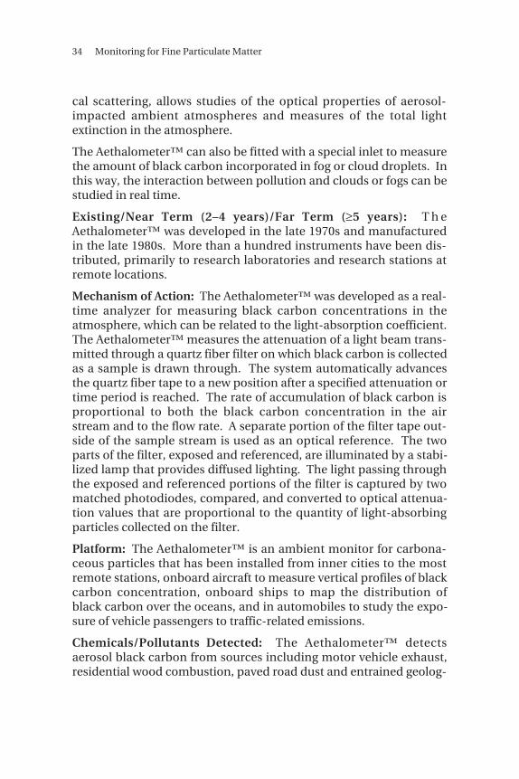
Mechanism of Action: The Aethalometer™ was developed as a real-time analyzer for measuring black carbon concentrations in theatmosphere, which can be related to the light-absorption coefficient.The Aethalometer™ measures the attenuation of a light beam trans-mitted through a quartz fiber filter on which black carbon is collectedas a sample is drawn through. The system automatically advancesthe quartz fiber tape to a new position after a specified attenuation ortime period is reached. The rate of accumulation of black carbon isproportional to both the black carbon concentration in the airstream and to the flow rate. A separate portion of the filter tape out-side of the sample stream is used as an optical reference. The twoparts of the filter, exposed and referenced, are illuminated by a stabi-lized lamp that provides diffused lighting. The light passing throughthe exposed and referenced portions of the filter is captured by twomatched photodiodes, compared, and converted to optical attenua-tion values that are proportional to the quantity of light-absorbingparticles collected on the filter.
Platform: The Aethalometer™ is an ambient monitor for carbona-ceous particles that has been installed from inner cities to the mostremote stations, onboard aircraft to measure vertical profiles of blackcarbon concentration, onboard ships to map the distribution ofblack carbon over the oceans, and in automobiles to study the expo-sure of vehicle passengers to traffic-related emissions.
Chemicals/Pollutants Detected: The Aethalometer™ detectsaerosol black carbon from sources including motor vehicle exhaust,residential wood combustion, paved road dust and entrained geolog-

Examples of Air Monitoring Technologies for Particulate Matter 35
ical material, coal-fired boilers at power plants, and restaurant grillsand residential cooking.
Accuracy/Reliability/Thresholds: The Aethalometer™ can detect anincrement of 1 nanogram of black carbon on its filter. The ambientconcentration to which this corresponds depends on the air flow rateand the integration time. Typical urban black carbon concentrationsrange from 1,000 to 50,000 ng/m3. If the black carbon concentrationis very low, the flow rate and the integration time must be increased.
Data Collection, Availability, and Processing Requirements: Thedata are processed through an algorithm and provided as units ofaerosol light absorption per cubic meter of air sampled. The instru-ment is self-calibrating. The Aethalometer™ requires no collectionand analysis of samples and no data tracking. Since the Aethalome-ter™ does not measure mass, it must be calibrated againt the EPA’sFRM.
Advantages: The Aethalometer™ is automatic and requires nooperator intervention for normal operation. The instrument is userfriendly, is fully operable upon unpacking, and is self-calibrating.Each roll of filter tape material can last from months to years,depending on the black carbon concentration at the sampling loca-tion.
The Aethalometer™ is not affected by temperature or relativehumidity, and its sampled air stream does not need to be precondi-tioned. In addition, it is not affected by interference from othercommon aerosol species, such as natural aerosols (e.g., sea salt), orsecondary anthropogenic aerosols (e.g., organics, sulfates, ornitrates).
Disadvantages: The Aethalometer™ does not make direct mea-surements of PM mass, but instead responds to the optically absorb-ing carbonaceous component of suspended particles from which themass must be inferred. Therefore, the Aethalometer™ must be cali-brated against the EPA’s FRM. In addition, the Aethalometer™ onlymeasures PM containing a carbonaceous component and cannotmeasure total PM, which can be made up of several different chemi-cal species, including organics, sulfates, and nitrates.
Cost: The cost of a basic Aethalometer™ is $9,950 and, with all theoptions possible, is less than $13,000.

36 Monitoring for Fine Particulate Matter
CONTINUOUS PARTICULATE MONITOR (CPM) [14, 15]
Applications: CPMs are variants of opacity meters used for stacksampling of PM emissions, and to monitor filter-bag bleedthrough,leaks, and broken-bag failures.
Existing/Near Term (2–4 years)/Far Term (≥5 years): CPMs arecommercially available for monitoring of PM emissions.
Mechanism of Action: The CPM is an optically based unit that uses amicroprocessor, transmitter, and receiver. It is a cross-stack mea-surement requiring two points of access. When light passes betweenthe transmitter and receiver, the momentary absorption of light bythe particles causes the receiver to see a modulating signal from thetransmitter. This signal modulation increases with and relates toincreasing dust concentrations. The signal can be calibrated with aknown dust sample or used as a relative monitoring signal. Thereceiver senses the signal modulation and converts it to a dust con-centration with the microprocessor.
Platform: CPMs are used for stack sampling and to monitor filter-bag bleedthrough, leaks, and breaks.
Chemicals/Pollutants Detected: CPMs are used to monitor PM,such as dust, dirt, soot, smoke, and aerosols (liquid droplets).
Accuracy/Reliability/Thresholds: The upper detection limit on par-ticle loading of the CPM is about 4 gr/dscf and the lower detectionlimit is about 4x10⁻⁶ gr/dscf. The particle size range over which theinstrument can effectively make measurements is 0.3 to 150 μm.
Data Collection, Availability, and Processing Requirements: CPMsdo not measure mass and must be calibrated against the FRM.
Advantages: CPMs can be used for continuous, in situ monitoringand have excellent sensitivity. CPM systems are easy to install andset up, and all adjustments can be made by the operator.
Since CPMs measure signal modulation resulting from moving par-ticles rather than diminishing intensity (brightness) of a light beam,the instrument is unaffected by conditions that cause false readingsin an opacity system, such as dirty sensors, misaligned sensors, agingsources, or aging detectors. The CPM will continue to operate with-

Examples of Air Monitoring Technologies for Particulate Matter 37
out drift until 93 percent of the transmitted light is blocked. This isnormally only 2 percent for typical opacity systems. Also, since itutilizes a diverging light source, it does not rely on lenses and insteaduses a small window to separate the sensor electronics from the gasstream. Windows are unaffected by accumulation of dust and alsounaffected by misalignment of the sensors. Because of this type ofoperation, CPMs can monitor even when moisture is present.
Disadvantages: CPMs are sensitive to particle size distribution andparticle characteristics. In addition, CPMs do not measure mass andtherefore must be calibrated against the EPA’s FRM.
Cost: CPMs are commercially available for approximately $15,000.

38 Monitoring for Fine Particulate Matter
THREE-COLOR INTEGRATING NEPHELOMETER WITHSIZE-SELECTIVE INLET [12, 18]
Applications: Integrating nephelometers measure the visual qualityof local ambient air by measuring the scattering of light due to parti-cles in continuous air samples. Nephelometers can be used in areascontaining local sources of pollution, areas where atmospheric con-ditions trap air pollutants, and general air quality monitoring net-works.
Existing/Near Term (2–4 years)/Far Term (≥5 years): The three-color integrating nephelometer is an existing technology that iscommercially available.
Mechanism of Action: The three-color integrating nephelometermeasures scattering of light due to particles in the air sample. Thenephelometer has an enclosed design and is vacuum tight. Thispermits drawing sample air through a particle-size-fractionatinginlet with a 2.5 μm cutpoint, so the instrument responds only to lightscattering by fine particles. This cutpoint excludes cloud or fogdroplets, drizzle, and other coarse particles from the sample flow.
The three-color integrating nephelometer makes measurements atthree colors and thereby provides information on the size distribu-tion of the fine-particle aerosol. For example, it is possible to reliablydistinguish between times when the aerosol is dominated by photo-chemically formed particles, which have a geometric mean diameter(Dgv) in the 0.1 to 0.3 μm range, and droplet mode particles, whichhave a Dgv in the 0.5 to 0.7 μm range. The instrument collects datacontinuously. The sample chamber of the three-color nephelometeris illuminated by a tungsten lamp, and dichroic filters separate thescattered light into three wavelength ranges with nominal values of450, 550, and 700 nm. The scattered light is detected by photomul-tipliers and photon-counting electronics.
Platform: Integrating nephelometers are used for ambient air moni-toring.
Chemicals/Pollutants Detected: Nephelometers measure the visualquality of local ambient air by detecting PM, such as dust, dirt, soot,smoke, and aerosols (liquid droplets) from sources including motorvehicle exhaust, residential wood combustion, paved road dust and

Examples of Air Monitoring Technologies for Particulate Matter 39
entrained geological material, coal-fired boilers at power plants, andrestaurant grills and residential cooking.
Accuracy/Reliability/Thresholds: The integrating nephelometer hasa local visual distance ranging from 0.4 to 16.0 km and an accuracy of±10 percent of the reading.
Data Collection, Availability, and Processing Requirements: Thedata files contain six light-scattering values in engineering units.These values are total scattering and backscattering at the red, green,and blue wavelengths. The three-color nephelometer is calibratedby filling it with Freon calibration gas. Since nephelometers do notmeasure mass, they must be calibrated against the EPA’s FRM.
Advantages: The integrating nephelometer is simple to install,operate, and calibrate. It is sensitive and self-calibrating. Preciseand accurate measurements can be made with few requirements foroperator maintenance. It offers continuous sampling, has low powerconsumption and a rugged compact design, and is small andlightweight enough for field use. The solid-state electronics of theinstrument are very stable. The instrument has proven to be anaccurate, precise, and reliable means of monitoring ambient lightscattering and has been applied in a wide range of operational andresearch monitoring programs in rural and urban areas.
Disadvantages: Integrating nephelometers are sensitive to particlesize distribution and particle characteristics. In addition, integratingnephelometers do not measure mass and therefore must be cali-brated against the EPA’s FRM.
Cost: Integrating nephelometers are commercially available forapproximately $8,000 to $9,000.

40 Monitoring for Fine Particulate Matter
LIGHT DETECTION AND RANGING (LIDAR) [19–23]
Applications: Lidar is used for remote detection of the presence,velocity and chemical makeup of “particles” ranging from aircraftand missiles to smoke, dust, and “invisible” gases. DifferentialAbsorption Lidar (DIAL) has been used to measure ozone concen-trations in the troposphere, aerosol distributions, air pollutantplumes, and air mass dispersion. Lidar has been used for military,commercial, and space applications.
Alternative Applications: Lidar can also be used to conduct oceano-graphic and meteorological research.
Existing/Near Term (2–4 years)/Far Term (≥5 years): Many investi-gations of persistent elevated pollution episodes, ozone, and aerosolshave been conducted with lidar since the early 1970s.
Mechanism of Action: Lidar uses the same principle as radar. Thelidar instrument transmits light out to a target. The transmitted lightinteracts with and is changed by the target. Some of this light isreflected (scattered) back to the instrument, where it is analyzed.The change in the properties of the light enables some property ofthe target to be determined. The time for the light to travel out to thetarget and back to the lidar is used to determine the range to the tar-g e t . DIAL is used to measure chemical concentrations (such asozone, water vapor, clouds, aerosols, and pollutants) in the atmo-sphere. A DIAL uses two different laser wavelengths, which areselected so that one of the wavelengths is absorbed by the moleculeof interest, and the other wavelength is not. The difference in inten-sity of the two return signals can be used to deduce the concentra-tion of the molecule being investigated.
Platform: Lidar is a remote-sensing technology that can be groundbased, or deployed on aircraft, satellites, and the space shuttle.
Chemicals/Pollutants Detected: DIAL can be used to detect ozone;water vapor; aerosols; pollutants, such as ethylene, benzene, ammo-nia, and hydrocarbons; and clouds.
Accuracy/Reliability/Thresholds: The accuracy of lidar is typicallyless than 10 ppb. Resolution varies depending on what is being

Examples of Air Monitoring Technologies for Particulate Matter 41
observed. For example, a 90-meter resolution can be obtained forozone, while a 15-meter resolution is obtained for aerosol.
Advantages: Lidar is extremely sensitive, has a large dynamic range,and can detect down to parts per billion.
Disadvantages: Issues of archiving and data processing arisebecause of the large amounts of data generated by lidar.


43
REFERENCES
1. U.S. Environmental Protection Agency, EPA Proposes AirStandards for Particulate Matter & Ozone, Press Release,November 27, 1996. URL: http://ttnwww.rtpnc.epa.gov/naaqspro/press.htm
2. U.S. Environmental Protection Agency, EPA’s RevisedParticulate Matter Standards, Fact Sheet, July 17, 1997. URL:http://ttnwww.rtpnc.epa.gov/naaqsfin/pmfact.htm
3. U.S. Environmental Protection Agency, EPA’s MonitoringRequirements for Particulate Matter, Fact Sheet, July 17, 1997.URL: http://ttnwww.rtpnc.epa.gov/naaqsfin/pmonfact.htm
4. U.S. Environmental Protection Agency, EPA’s Updated CleanAir Standards, Fact Sheet, July 16, 1997. URL: http://ttnwww.rtpnc.epa.gov/naaqsfin/naaqsfac.htm
5. U.S. Environmental Protection Agency, Air Quality Criteria forParticulate Matter, EPA/600/P-95/001aF-cF. URL: http://www.epa.gov/ORD/WebPubs/execsum.html
6. U.S.Environmental Protection Agency, “National Ambient AirQuality Standards for Particulate Matter; Final Rule, Part II,”Federal Register, 40 CFR Part 50, July 18, 1997.
7. U.S. Environmental Protection Agency, Health and Environ-mental Effects of Particulate Matter, Fact Sheet, April 3, 1997.URL: http://ttnwww.rtpnc.epa.gov/naaqspro/pmhlth.htm

44 Monitoring for Fine Particulate Matter
8. The Ambient Air Monitoring Program, The Ambient MonitoringTechnology Information Center (AMTIC), Office of Air QualityPlanning and Standards. URL: http://www.epa.gov:8080/oar/oaqps/qa/monprog.html
9. U.S. Environmental Protection Agency, “Revised Requirementsfor Designation of Reference and Equivalent Methods for PM2.5and Ambient Air Quality Surveillance for Particulate Matter;Final Rule, Part IV,” Federal Register, 40 CFR Parts 53 and 58,July 18, 1997.
10. U.S. Environmental Protection Agency, Allocation of GrantFunds for PM-2.5 Monitoring, Memorandum, January 9, 1998.URL: http://ttnwww.rtpnc.epa.gov/implement/98pmallo.htm
11. J.G. Watson, J.C. Chow, H. Moosmüller, M. Green, N. Frank, andM. Pitchford, Guidance for Using Continuous Monitors in PM2.5
Monitoring Networks (Draft), March 6, 1998. URL: http://www.epa.gov/ttn/amtic/files/ambient/pm25/ec3698r.pdf
12. Northern Front Range Air Quality Study (NFRAQS) Website.URL: http://charon.cira.colostate.edu/
13. Rupprecht & Patashnick Co., Inc., 25 Corporate Circle, Albany,NY 12203 USA, phone: (518) 452-0065, fax: (518) 452-0067.URL: http://www.rpco.com:80/index.htm
14. BHA Group, Inc., 8800 East 63rd Street, Kansas City, Missouri64133. URL: http://www.bhagroup.com/index.htm
15. Technical Support Document for HWC MACT Standards (Draft)Volume IV: Compliance with the Proposed MACT Standards—EPA Office of Solid Waste and Emergency Response (5305),February 1996.
16. Ralph Robertson, P.E., RBM Consulting & Research Inc., 5400Glenwood Avenue, Raleigh, NC 27612, phone: (919) 510-0376(direct) or (919) 510-5102 (main), fax: (919) 510-5104.
17. Magee Scientific Company, 1750 30th Street, Boulder, CO80303, phone: (808) 934-7612. URL: http://www.mageesci.holowww.com:80/

References 45
18. Belfort Instrument Company, 727 South Wolfe Street,Baltimore, MD 21231. phone: (410) 342-2626, fax: (410) 342-7028. URL: http://www.belfort-inst.com/integrating_nephelometer_ series_1590.html
19. National Technology Transfer Center (NTTC) Database, NTTC,Wheeling Jesuit College, 316 Washington Avenue, Wheeling,West Virginia 26003, phone: 1-800-ENV-6676, fax: (304) 243-2539.
20. U.S. Army Biological Detection Program—U.S. Army BiologicalDetection Program briefing presented to Dr. Bernard Rostker,Special Assistant to the Secretary of Defense for Persian Gulf Ill-ness Matters.
21. What is LIDAR?—NASA MSFC Electro-Optics Branch (EB53).URL: http://eo.msfc.nasa.gov:80/general/lidarqst.html
22. NASA Langley’s LIDAR Applications Group. URL: http://asd-www.larc.nasa.gov/lidar/lidar.html
23. NOAA Atmospheric Lidar Division. URL: http://www2.etl.noaa.gov/