monitoring flow - operating plants in the chemical … process industry. the sitrans fc430 is suited...
TRANSCRIPT

2009
Flow eHandbook
Monitoring Flow

Not just solenoids*
*While we love the fact that our solenoid valves have earned us the reputation
of being a quality brand with long life-cycle products, we’ve got more than
just solenoids up our sleeve. From Process Solutions to Sensors, Mass Flow
Controllers to Pneumatically Actuated Valve banks and Ball Valves – and, of
course – we’re still producing those world-class solenoid valves too! We’d love to
send a free catalog and show you more. Email [email protected] and
request one today.
www.burkert-usa.com 800-325-1405Online ordering now available at www.BuyBurkert.com
2
3
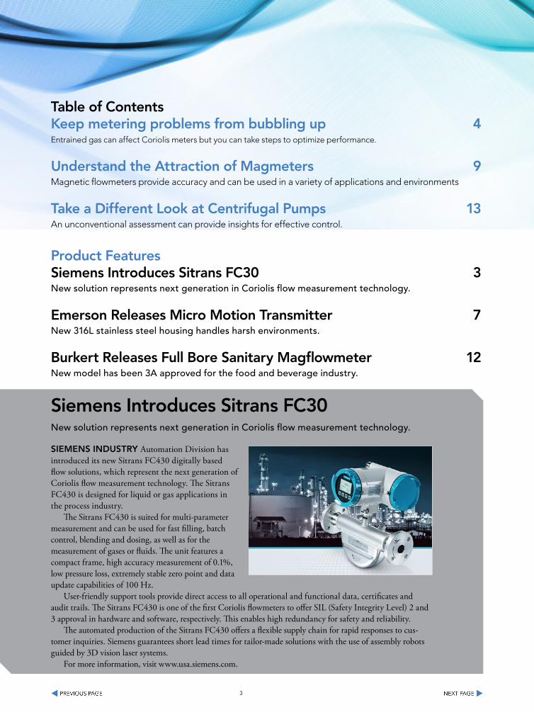
Siemens Introduces Sitrans FC30New solution represents next generation in Coriolis flow measurement technology.
SIeMenS InduStry Automation Division has introduced its new Sitrans FC430 digitally based flow solutions, which represent the next generation of Coriolis flow measurement technology. The Sitrans FC430 is designed for liquid or gas applications in the process industry.
The Sitrans FC430 is suited for multi-parameter measurement and can be used for fast filling, batch control, blending and dosing, as well as for the measurement of gases or fluids. The unit features a compact frame, high accuracy measurement of 0.1%, low pressure loss, extremely stable zero point and data update capabilities of 100 Hz.
User-friendly support tools provide direct access to all operational and functional data, certificates and audit trails. The Sitrans FC430 is one of the first Coriolis flowmeters to offer SIL (Safety Integrity Level) 2 and 3 approval in hardware and software, respectively. This enables high redundancy for safety and reliability.
The automated production of the Sitrans FC430 offers a flexible supply chain for rapid responses to cus-tomer inquiries. Siemens guarantees short lead times for tailor-made solutions with the use of assembly robots guided by 3D vision laser systems.
For more information, visit www.usa.siemens.com.
table of ContentsKeep metering problems from bubbling up 4Entrained gas can affect Coriolis meters but you can take steps to optimize performance.
understand the Attraction of Magmeters 9Magnetic flowmeters provide accuracy and can be used in a variety of applications and environments
take a different Look at Centrifugal Pumps 13An unconventional assessment can provide insights for effective control.
Product FeaturesSiemens Introduces Sitrans FC30 3New solution represents next generation in Coriolis flow measurement technology.
emerson releases Micro Motion transmitter 7New 316L stainless steel housing handles harsh environments.
Burkert releases Full Bore Sanitary Magflowmeter 12New model has been 3A approved for the food and beverage industry.
4
Keep metering problems from bubbling upEntrained gas can affect Coriolis meters but you can take steps to optimize performance.
and environments
By Tim Patten, Micro Motion, Inc.
CorIoLIS MeterS have long been used very successfully on single-phase f luids. However, liquids that contain bubbles (air or gas) cause dynamic changes to a Coriolis meter that are not present in a single-phase f luid and that lead to measurement errors.
A Coriolis meter operates by “driving” one or two tubes at a resonant, or natural, frequency. In the meter, the electronics (or transmitter) send a drive signal to the sensor that tracks the frequen-cy of the tube and maintains the proper vibration amplitude. Driving on the resonant frequency is important because it enables f luid density mea-surement and minimizes power requirements.
All modern Coriolis meters are intrinsically safe (IS), which limits the amount of power that is allowed to drive the sensor. Bubbles moving around in the liquid tremendously increase fluid damping, which results in power requirements that far exceed what IS restrictions permit. So, the tube amplitude significantly decreases. This condi-tion is sometimes called “stall,” although the tubes usually do continue to vibrate to some extent.
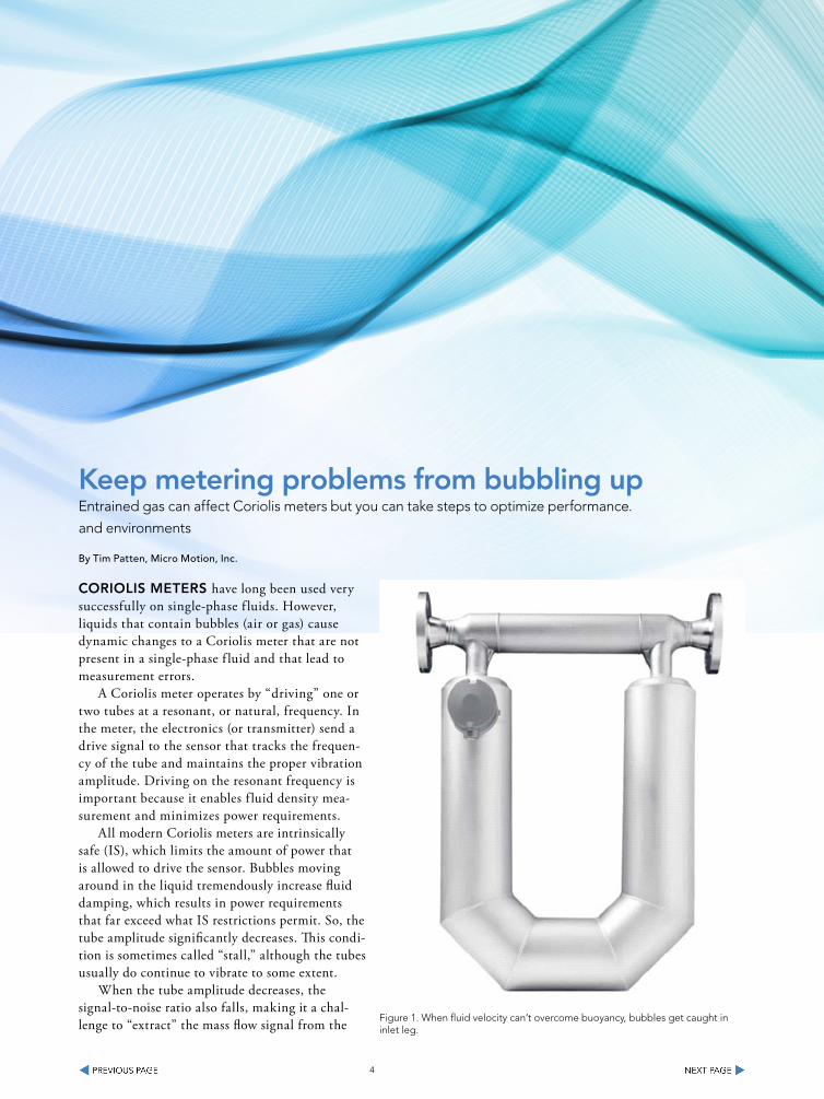
When the tube amplitude decreases, the signal-to-noise ratio also falls, making it a chal-lenge to “extract” the mass flow signal from the Figure 1. When fluid velocity can’t overcome buoyancy, bubbles get caught in
inlet leg.

5
relatively high level of noise. Older analog signal-processing techniques are highly sensitive to entrained air because signal amplitude is low and noise is high; no algorithm is available to enhance the measurement signal, thereby improving the signal-to-noise ratio. In contrast, digital signal processing (DSP) can effectively filter the noise to yield a good stable measurement so long as the tube is vibrating, even at reduced amplitudes.
Note: Even with DSP, when gas is present in a liq-uid stream the meter can only provide total-product density (including the gas), not liquid-only density.
tHe IMPACt oF FLuId dynAMICS
Coriolis meters are not sensitive to flow profile and other disturbances that affect other metering technologies. For instance, since the fundamental measurement of “delta T” comes from the relative values of each of two tubes in bent-tube designs, swirl upstream of the meter doesn’t impact the mea-surement because it doesn’t matter how much flow
goes through one tube or the other. Accuracy is not degraded even when one tube is completely plugged.
However, when gas is present in a liquid, the flow profile can become a concern. Although the fundamental measurement is unaffected (that is, the relative delta T), the tubes can become imbal-anced due to the large density difference between them (air in one, liquid in the other, for instance). An imbalance can cause meter zero errors; there-fore, measuring low flow rates can be problematic.
An equally significant problem occurs at rates too low to sweep bubbles out of the tubes. If the fluid velocity is less than approximately 0.6 m/s, air will “hang up” in tube regions where the flow is against gravity (Figure 1). Bubbles get caught in the inlet tube leg because fluid velocity is not great enough to push the bubbles down and out against gravity forcing the bubbles up. This issue is present in any bent-tube meter design because at some loca-tion in the tube the fluid velocity is fighting gravity.
The solution is to keep flow rate high enough
Figure 2. Even at low flow rate, measurements for 10,000-cP toothpaste with 2-5% void fraction are within specification.

6
such that fluid velocity can purge the sensor of air. A rate of 20% of meter nominal flow (1 m/s in the flow tube) or higher is adequate to completely purge the meter of bubbles and give good perfor-mance. In a U-shaped meter, mounting the sensor in a vertical pipe run with flow going up helps to keep the bubbles moving through the meter.
tHe roLe oF FLuId ProPertIeS
Pressure, f luid temperature and viscosity all impact how a Coriolis meter deals with varying levels of entrained air.
As pressure increases or decreases, the appar-ent void fraction changes, of course. This means, for instance, if two meters are piped in series, the downstream meter is at a distinct disadvantage because the pressure is lower and therefore the void fraction is higher.
Temperature plays a minor role, in that it af-fects viscosity and surface tension. It also impacts void fraction to a small degree (higher tempera-ture results in higher void fraction).
Viscosity is a very important fluid parameter because it directly influences the propensity of the fluid to hold up air (or gas). In a low-viscosity
liquid such as water, air bubbles coalesce from finely distributed small bubbles into large ones that collect at high points in the line. In contrast, if the bubbles stay finely distributed, as happens in high-viscosity liquids, they will be purged from the meter easily and not collect — and metering will be accurate. Figure 2 shows results for toothpaste with a viscosity of 10,000 cP and entrained air level between 2 and 5%. Rates are quite low for a 2-in. meter (<0.6 m/s) yet performance is well within specification.
The opposite viscosity extreme is water where air will always tend to separate. If velocity is high, bubbles tend to stay finely divided, which helps to keep the air well mixed. Figure 3 shows very good performance because mixing is good due to the high flow rate (38,000 kg/h). If the velocity is low, bubbles collect at locations in the meter flow tubes or piping where the flow direction is against gravity. Errors can easily exceed 5% if the velocity is less than 0.6 m/s — and therefore mixing is poor.
Future IMProveMentS
Transmitters in development will enable accurate measurement of lower rates. There will always be a physical limit to the minimum rate that can
Figure 2. Even at low flow rate, measurements for 10,000-cP toothpaste with 2-5% void fraction are within specification.
7
be measured because of the previously described separation issues. However, noise rejection im-provement with new DSP techniques will allow the minimum rate to be pushed lower.
A significant problem with any two-phase flow (water/air, dog food with solids suspended in water, oil/gas, etc.) is at zero flow. When the flow is stopped, the multiple phases separate by gravity, prompting an imbalance in the tube. This imbal-ance causes an apparent meter zero change. Work on signal processing improvements to address this problem is currently a significant area of research.
A SPeCIAL CASe
Empty-full-empty batching can pose a related measure-ment issue. Such batching is most common to avoid cross-contamination of products when filling large tanks such as rail cars or trucks. Therefore, the loading line is purged with air or other inert gas between loads, leaving the meter empty before and after the batch.
Generally, this application is not too difficult because the batches tend to be long (greater than one minute). Any transient meter behavior at the beginning and end of the batch is small compared to the whole batch, so errors are “washed out.”
However, when batches are short (less than one minute), the transient errors can account for a signifi-cant fraction of the total error. Air may be entrained for a brief period, but the main issue is the time it takes to fill the meter with fluid. For instance, an ap-plication running at 3 m/s will take about 0.1 s to fill if the tube length is 0.3 m; an application at 0.3 m/s will take a full second simply to fill the meter. Experi-ence has shown that if the meter fill-time is less than 0.1 sec., good batching performance can be achieved, regardless of the meter’s tube geometry.
tIM PAtten is director of measurement technology for
Micro Motion, Inc., Boulder, Colo. E-mail him at Tim.Pat-
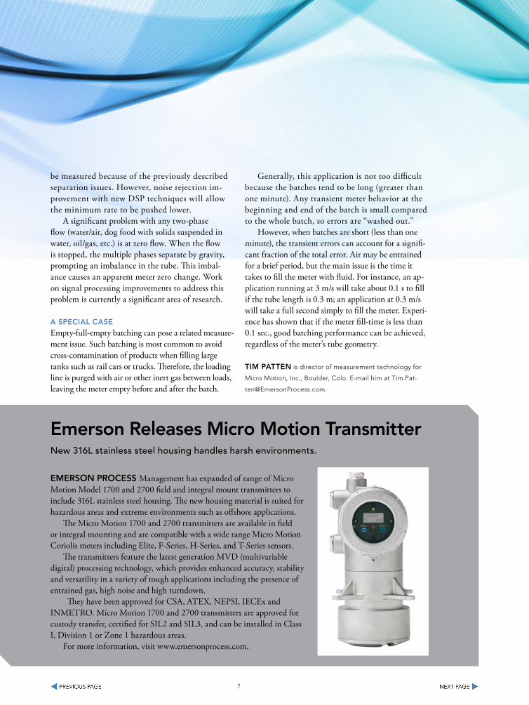
emerson releases Micro Motion transmitterNew 316L stainless steel housing handles harsh environments.
eMerSon ProCeSS Management has expanded of range of Micro Motion Model 1700 and 2700 field and integral mount transmitters to include 316L stainless steel housing. The new housing material is suited for hazardous areas and extreme environments such as offshore applications.
The Micro Motion 1700 and 2700 transmitters are available in field or integral mounting and are compatible with a wide range Micro Motion Coriolis meters including Elite, F-Series, H-Series, and T-Series sensors.
The transmitters feature the latest generation MVD (multivariable digital) processing technology, which provides enhanced accuracy, stability and versatility in a variety of tough applications including the presence of entrained gas, high noise and high turndown.
They have been approved for CSA, ATEX, NEPSI, IECEx and INMETRO. Micro Motion 1700 and 2700 transmitters are approved for custody transfer, certified for SIL2 and SIL3, and can be installed in Class I, Division 1 or Zone 1 hazardous areas.
For more information, visit www.emersonprocess.com.

8
The Emerson logo is a trademark and a service mark of Emerson Electric Co. © 2011 Emerson Electric Co.
YOU CAN DO THAT
Every single flowmeter I calibrateinterrupts my process.There must be a way to verify meterswithout putting my plant and people at risk.
Verify flowmeter performance in place with Micro Motion Smart Meter Verification. Determining measurement integrity and performance of every meter in line means never stopping your process flow. Emerson’s Smart Meter Verification for Micro Motion Coriolis meters is the only automatic diagnostic tool that eliminates the need to break process seals, allowing you to avoid potential safety issues and costly process flow interruptions. So to keep your workers safe and your operation running, go to EmersonProcess.com/Verification

understand the Attraction of MagmetersMagnetic flowmeters provide accuracy and can be used in a variety of applications
and environments
By David W. Spitzer
MAgnetIC FLowMeterS are among the most versatile of f lowmeter technologies. These meters measure liquid velocity, from which the volumetric f low rate is inferred. The measure-ment is linear with liquid velocity and exhibits a relatively large turndown. In addition, the range of accurate f low measurement is relatively large and easy to change after installation.
Straight-run requirements are relatively short, so magnetic f lowmeter technology can be applied where limited straight run is available. In addi-tion, the technology has no Reynolds number constraints, so it can be used for liquids with high or varying viscosity. However, liquid electrical conductivity constraints must be satisfied for these f lowmeters to function.
The only wetted parts of the f lowmeters are the liner and electrodes, both of which can be made from materials that can withstand cor-rosion. This makes the f lowmeters suitable for use in chemical plants where corrosion may be a concern. Two-wire magnetic f lowmeters are available that do not require power wiring. These can replace an existing f lowmeter using the exist-ing conduit or wiring with little or no electrical rework.
PrInCIPLe oF oPerAtIon
Magnetic flowmeters use Faraday’s Law of electro-magnetic induction to determine the velocity of a liquid flowing through a pipe. Following Faraday’s Law, flow of a conductive liquid through a magnetic field will generate a voltage signal. This signal is sensed by electrodes located on the flow tube walls. When the coils are located externally, a non-conductive liner is installed inside the pipe to electrically isolate the electrodes and prevent the signal from being shorted. For similar reasons, non-conductive materials are used to isolate the electrodes for internal coil designs.
The fluid itself is the conductor that will move through the magnetic field and generate a voltage signal at the electrodes. When the fluid moves faster, it generates more voltage. Faraday’s Law states that the voltage generated is proportional to the movement of the flowing liquid. The transmitter processes the volt-age signal to determine liquid flow.
SeLeCtIon FACtorS
Many factors must be considered when selecting a flowmeter, including the ambient conditions to which the flowmeter primary and transmitter will be exposed. For the most part, the ambient temperature rating of the flowmeter primary is higher than that
9

10
of the transmitter and does not limit applicability. Many primary and transmitter enclosures that are rated for NEMA 4X or IP67 provide adequate pro-tection against ambient humidity and precipitation encountered in outdoor installations.
Operating conditions inside the pipe include pressure, temperature and liquid conductivity. In addition, the liquid can be corrosive or abrasive. These conditions are typically addressed using appropriate mechanical design and material selection. Pressure requirements are addressed by appropriate design of the flow tube for the application. One supplier makes a specially designed magnetic flowmeter that can withstand 1,500 to 2,000 bar (more than 20,000 psi).
Many primaries are available with polytetrafluoro-ethylene (PTFE) or perfluoroalkoxy (PFA) liners that are rated to about 266 Degrees F and 356 Degrees F
(130 Degrees C and 180 Degrees C), respectively. Less expensive liners rated to lower temperatures are often available to handle less demanding applications. Appropriate electrode and liner material selection can reduce the effects of corrosion and abrasion. Take care when using ceramic liners because they can shatter when temperature gradient constraints are exceeded.
Whereas the conductivity of the liquid in a typical magnetic flowmeter must be maintained above about 5 mixro-Siemens/cm (micro-S/cm), special low-conduc-tivity designs are available that operate as low as about 0.01 micro-S/cm. Some flowmeters require more than 50 micro-S/cm, however, they are low-cost units that are often applied to water or wastewater service where this conductivity is usually not a constraint.
The amount of straight-run pipe required to achieve the stated accuracy of the flowmeter is a reflection of the quality of the design and the tight-ness of the accuracy specification. In many applica-tions, these flowmeters will function accurately with about three nominal pipe diameters upstream and two nominal pipe diameters downstream of the electrode.
Magnetic flowmeter operation requires good electrical connections between the electrodes and the liquid. The quality of this connection can degrade if an electrode becomes coated or corroded;
this can compromise AC flowmeter accuracy by shifting the zero, and may cause the flowmeter to fail to operate. The advent of DC-pulse excitation transmitters reduced much of the need to address this issue. In addition, some manufacturers have designed their transmitters to exhibit a relatively high input impedance to help decrease the effects of connection quality.
Magnetic flowmeter coils can use and store sig-nificant amounts of energy relative to the amount of energy needed to cause ignition. Most magnetic flow-meter transmitters are designed to be non-incendive, so normal transmitter operation will not cause ignition. However, when installed in some hazardous locations, formal approval is required, and the transmitter must be designed and installed to address the hazard.
A hazard may be present not only in the general location of the primary and transmitter, but also inside the pipe where the electrodes can provide a source of ignition. To mitigate this hazard, the circuits of some designs limit the energy available at the electrodes to an amount less than that required for ignition.
Maintaining equipment is simplified when self-diagnostics are available to help the user. The extent and quality of the diagnostics and their ease of use varies by manufacturer. Changing ranges is easier and more accurately performed in a digital manner. Potentiometer adjustments and step switches are more prone to problems.
otHer ConSIderAtIonS
The market for magnetic flowmeters is competitive, so prices are relatively low. Magnetic flowmeters for water and wastewater service can be economical due to the economies of scale and the relatively low cost of liners and electrodes for this service. However, applying magnetic flowmeters to corrosive or abrasive services can significantly increase the cost of the meters.
Magnetic flowmeters for use in the chemical in-dustry are typically more expensive than vortex shed-ders. In some applications, the cost can rival that of turbine flowmeter or orifice-plate flowmeter systems. Magnetic flowmeters are typically more economical than Coriolis mass flowmeters.

11
FLowMeter PerForMAnCe
The purpose of installing a flowmeter system is to accurately measure flow in a reliable manner. Issues related to physical properties, process parameters, electronic features and interconnections are often given much consideration. Relatively little empha-sis, however, is given as to how well the flowmeter will perform its intended purpose. Adding to the confusion are the differences in how performance is expressed and the incomplete nature of the avail-able information. Nevertheless, the quality of flow measurement should be a concern.
The performance of a flowmeter is quantified by its accuracy statements. The reader must under-stand not only which parameter is being described, but also the manner in which the statement is expressed. In flow measurement, parameters are commonly described in terms of a percentage of the actual flow rate, a percentage of the full scale of rate, or a percentage of the meter capacity. These terms are mathematically related, so it is possible to convert one to another (Table 1). Note that when compared on a common basis, such as percent of rate, these statements describe significantly differ-ent performance.
Other terminology may be used to express these concepts. When this occurs, confirm exactly what the other terms mean so they can be understood.
Performance statements apply to a range of flow or, stated differently, between a minimum and maximum flow velocity. It is important to identify the range in which the statement applies because performance can be significantly degraded or undefined when the flowmeter operates outside of this range.
Complicating the issue are some flowmeters that have different performance statements for differ-ent measurement ranges. For example, a flowmeter may have a reference accuracy of 0.25% of rate from velocities of 1 to 10 m/s, and an absolute er-ror of 0.0025 m/s from 0.1 to 1 m/s. Performance is undefined below 0.1 m/s. Table 2 describes this performance using the above information. Note how performance degrades at low flows.
PerForMAnCe CLAIMS
For the most part, the claims made by suppliers regarding magnetic flowmeters are true statements, even though they may seem extraordinary. The problem is that the statement may be incomplete, and may not include certain facts and information that clarify the statement. Sometimes claims are simplified for convenience and easier understand-ing. However, in many cases, further investigation may reveal other motives for doing so.
For example, consider a magnetic f lowmeter that has a reference accuracy of 0.25% of rate and a turndown of 1,000:1. The implication is that the f lowmeter can measure within 0.25% of rate over a 1,000:1 range of f low. Taken individually, both parts of the claim are likely true statements. Yet when combined, they can be misleading by omission. Further investigation will show that the reference accuracy of 0.25% of rate applies only within a range of f low rates. Below the minimum f low rate of the range, the reference accuracy becomes a fixed absolute error. So as the f low rate decreases, the accuracy expressed as a percentage of rate will increase.
Assuming that the reference accuracy of 0.25% of rate applies between 5% and 100% of meter capacity, and that between 0.1% and 5% of meter capacity, the reference accuracy is fixed at the abso-lute error at 5% of meter capacity. Table 3 calculates reference accuracy throughout the range of flows.
This illustrates that above 0.5 m/s, the reference accuracy is 0.25% of rate and that the turndown is 10/0.01 or 1,000:1, both as claimed. What is not stated in the claim is that the reference accuracy degrades below 0.5 m/s and can approach 12.5% of rate. Also not stated is that in actual installa-tions, flows near meter capacity would rarely be encountered, so the 1,000:1 turndown would rarely be achieved. Assuming a more reasonable full-scale calibration range of 0 to 2 m/s, this flowmeter would achieve a 0.25% of rate reference accuracy from 0.5 to 2 m/s, or a 4:1 turndown, and only a 200:1, or 2/0.01, turndown when the stated perfor-mance at low flow rates is included.

12
In addition to high turndown, some suppliers claim that their f lowmeter operates at extremely low f low rates. Consider a claim to measure velocity as low as 0.01 m/s. For a meter with a capacity of 10 m/s, this corresponds to a 1,000:1 turndown. Although the f lowmeter may operate at this f low rate, Table 3 shows that it does so with a reference accuracy of 12.5% of rate.
Statements about magnetic flowmeters often claim high reference accuracy. What often is not stated is that it may apply over a range of higher flows, and much of this range may not be encoun-tered in actual operation. Furthermore, the refer-ence accuracy as a percentage of rate generally degrades or is undefined at lower flow rates (see tables). When the calibrated full-scale is low, and the high reference accuracy statements are limited to a small range of high flow rates, the stated reference accuracy may not be achieved.
In general, reference accuracy should be clear-ly and completely stated for all flow rates prior to performing any analysis. The range of applicabil-ity of the high accuracy statement and the actual operating flow range should be compared.
Magnetic flowmeters are among the most versatile of flowmeter technologies. However, the user should be aware of the manner in which their application and operation are described in order to ensure that the proper magnetic flowmeter is selected and installed.
dAvId w. SPItzer has more than 25 years of experience in
specifying, building, installing, commissioning and trouble-
shooting process-control instrumentation. Spitzer is a principal
in Spitzer and Boyes LLC, which offers consulting services for
the process industries in addition to product development,
marketing and distribution consulting for manufacturing and
automation companies.
Burkert releases Full Bore Sanitary MagflowmeterNew model has been 3A approved for the food and beverage industry.
BurKert HAS released the sanitary full bore magf lowmeter Type 8056, a new model that has been 3A approved for use in the food & beverage industry. The magf lowmeter comes standard with PTFE lining, 2x 316L SS electrodes, 304ss body and both analog and digital pulse output.
The new model consists of a magnetic sensor fitting Type S056 con-nected to an electronics Type SE56 (blind in compact version or with display in compact or remote version). It is designed for applications with liquids with a minimum conductivity of 5 μS/cm.
Combined with a valve as the actuating element, the complete full bore sanitary magf lowmeter is designed to control high-precision dosing operations and f low measurement in the food & beverage and pharma-ceutical industries. Other features include continuous measurement or batch control; and sanitary version certificate.
For more information, visit www.burkert-usa.com.
13
take a different Look at Centrifugal PumpsAn unconventional assessment can provide insights for effective control.
By Andrew Sloley, Contributing Editor
oFten, CrItICAL understanding of a system comes from turning the common analysis on its head. With centrifugal pumps, this means thinking that flow results from back-pressure on the pump discharge, not that pump discharge pressure varies with flow rate.
This unconventional approach was crucial in addressing a troublesome control system for the overhead of a natural gas liquids plant’s debutanizer, which goes to an accumulator downstream of a reflux pump (Figure 1). Varying the rate of liquid product controls tower pressure. A dual-range controller handles the reflux drum pressure -- one valve lets in fuel gas to pressurize the system when pressure drops, another vents the drum when pressure rises to too high a level.
This rather odd system did not work. The reflux pump cavitated all the time and pressure control was erratic.
The owner, which acquired the unit during a company buy-out, lacked tower drawings, exchanger information, pump curves, control valve informa-tion and historical operating data. Current operating personnel had no experience with the unit and never had seen it work stably.
Lack of information doesn’t justify ignoring the problem. So, let’s examine this system’s fundamentals and explore the most serious shortcomings.
Centrifugal analysis starts by looking at two things: the system curve and the pump curve. The system curve is the head loss required versus flow rate through the system. The pump curve is the dynamic head generated by the centrifugal pump. The intersec-tion of the system and pump curves defines the flow rate the system will get.
We most commonly attain the required flow rate by
adjusting the system curve by adding an extra pressure drop via a control valve. Alternatively, we can change the pump curve using an adjustable speed drive.
In Figure 1, the reflux control valve is a hand-op-erated control valve (HCV). The reflux system doesn’t include an automated pressure drop. It essentially has a fixed system curve. This brings us to thinking about the pump operation: pump flow stems from back-pressure on the pump.
Now, let’s consider the tower pressure-control system. PC3 adjusts the product flow out of the system with the intent of changing the liquid level in the condensers. Varying wetted condenser area on the process side allows for pressure control. This is a simple, fast-acting and effective system for total condensation services.
Meanwhile, the product drum pressure-control system maintains a constant destination pressure for the net product from the reflux pump.
The static head to the top of the tower far exceeds the pressure change between the tower and product drum.
The problem comes from how the systems interact. The pressure control system requires level to exist somewhere up in the heat exchangers. Think of the exchangers and piping as a tall narrow vessel -- if more liquid exits a vessel than goes in, the level drops, and vice versa. The pressure control system should perform similarly to a tight level control system.
The system curve for the reflux stream includes two components: static head and system pressure drop. Static head doesn’t change with flow rate, but system pressure drop does. If static head makes up most of the system curve, the curve is relatively flat. Flat system curves create large flow rate changes from small pressure drop changes.

14
The flow rate out of the vessel (heat exchangers and piping) is very sensitive to changes in the HCV position. The HCV’s purpose is to generate enough pressure drop in the reflux line so the unit can operate in a sweet spot where the pressure control system will work. In this case, we suspect the sweet spot is too small. The back-pressure on the pump imposed by the HCV usually is too low. At low back-pressure the pump capacity exceeds the liquid rate. More liquid is leaving the vessel (heat exchangers and piping) than going in. Liquid level drops quickly. Finally, the pump cavitates.
How can we address this problem?One way is to try to put as much dynamic pres-
sure drop on the HCV as tolerable. This makes the reflux system curve steeper, which gives more stable control. This is cheap and quick.
A second, and better, approach automates the
HCV. Control systems should transfer a disturbance from where it’s important to where it’s not. What’s important here is the flow rate out of the “vessel” -- so we can maintain tight level control. We must move the disturbance to something unimportant. Many different configurations are possible. The cloud in Figure 1 shows one of the simplest and easiest options. A strap-on ultrasonic flow meter along with a bolt-on actuator on the HCV enables fully automated control of the overhead system. The disturbance now is in the valve pressure drop -- an unimportant spot.
There are other ways to approach this problem. But a fundamental understanding of the system comes from looking at the pump backwards.
Andrew SLoLey is a Chemical Processing Contributing
Editor. You can e-mail him at [email protected]
Debutanizer OverheaDFigure 1. Lack of an automated pressure drop in the reflux system made control difficult.

Answers for industry.
Because size and safety matterSITRANS FC430 – the market’s most compact Coriolis solution
usa.siemens.com/Coriolis
Scan to explore the future of fl ow measurement
© 2
01
2 S
iem
ens
Ind
ust
ry,
Inc.
Building on a strong tradition of innova-tive thinking, Siemens has designed the next generation of Coriolis flowmeters for excellence in performance, safety and user-friendliness: the SITRANS FC430.
This digitally-based flow solution features market-leading compactness, very high accuracy of 0.1%, low pressure loss, extremely stable zero point and best-in-class data update with 100 Hz high-speed signal transfer.
Unique support tools provide direct access to all operational and functional data, certificates and audit trails. The SITRANS FC430 is amongst the first Coriolis flowmeters to offer SIL 3 certification on the system, meeting the highest standards of safety and reliability.
With the SITRANS FC430, process optimization has never been easier – or more innovative.
• Smallest footprint – Shortest lay length of any Coriolis sensor in its size class
• SensorFlash – a micro SD card with backup data, settings, certificates and audit trails uploadable to any PC
• Robust Sensor Frame – with high resistance to process noise and vibrations for excellent 0.1% accuracy
Ad SITRANS FC430_Fluid_eHandbook_JULY2012.indd 1 6/19/2012 12:33:45 PM 15

16
Want to learn more about the products highlighted in this eHandbook?
Just click here
Complete the information request form
(pictured below) and we will provide you with additional information as requested by you.