monitoring a criblock retaining wall - … no. cdoh-dtp-r-90-6 monitoring a criblock retaining majid...
TRANSCRIPT

Report No. CDOH-DTP-R-90-6
MONITORING A
CRIBLOCK RETAINING
Majid Derakhshandeh
Colorado Department of Highways 4201 East Arkansas Avenue Denver. Colorado 80222
Final Report December 1990
Prepared in cooperation with the
~ U.S. Department of Transportation o Federal Highway Administration
~
WALL

Technical Report Documentation Page
I. A.,o",' No.
CDOH-DH-R-90-6
4. Ti,l. o"d 5 .. Io'i,l. 5. ~ .,." c •••
Monitoring a Criblock Retaining Wall - .... 1qqn
6. P.,Io",,,,,, O"."i •• 'i"" Cod.
HPR-1567D/74.50 I-:;--~~-:-~ __________________________ --! 8. Po,fo,,,,i,., O,go"i •• ,io" Ro,o,r N •.
I 7. A",horl.)
Majid Derakhshandeh 9. P."O","", O"oniu,io" N_. and Add, ...
Color"ado Department of Highways 4201 East Arkansas Avenue
CDOH-DH-R-90-6 10. Work U,.i, N •• (TRAIS)
II. CO""OCI or G,O"' No.
HPR 1567D !-:D:-::e:-n_v:-e_r..;.,_C_O __ 8..;;0..;;2;.;;2_2 ____ ~-----------------__.j 13. Typ. of R.port o"d P.,iod C.n,.d
12. Spon •• ,i", A,Oftey N.",. oncl Add, ...
Colorado Department of Highways 4201 East Arkansas Avenue Denver, co 80222 15. S"ppl.",.", .. ,. N., ..
Final Report
Prepared in cooperation with the U. S. Department of Transportation, Federal Highway Administration 16. Ab.troct
Two criblock retaining walls were constructed on both ends of a bridge on project BRO 0057(2) on County Road 17 in Pitkin County in western Colorado.
This study was initiated to evaluate the post-construction performance of this proprietary retaining wall system. The walls were completed during March 1989, and their movements were monitored through July 1990.
The results of the monitoring program indicated that the wall movements were limited to less than 3/4 of an inch during the 17 months monitoring period, and the walls appear to be in satisfactory working condition. The appearance of the criblock retaining walls as well as their durability can make this retaining wall system competitive with the other retaining wall systems when applicable.
Implementation
This report will be distributed internally to allow the staff bridge design group, as well as other·branches in the Highway Department, to make their own determinations based on the observations of th"is study.
17. 1C0y w., ••
Criblock, Retaining Wall Monitoring
19. Socurity CI ... II. lof Ifti. ropo,t)
Unclassified
FDrm DOT ~OO.7 (1-72)
No Restrictions: This report is available to the public through the National Information Service springfield, Virginia 22161
20. Socu,ity Cluei'. (or 'hie POlO) 21.N ••• fPo, •• 22. P,iu
Unclassified 27
ReprocluctiOft of campletocl pat. euth.riaocl
i i

TABLE OF CONTENTS
SECTION TITLE PAGE NO.
I. Introduction...................... 1 II. Background. .. . . . . .. . .. . . . . . .. . .. . .. . . . .. .. 1
A) Mechanics of a concrete crib lock retaining wall............ 1
B) History of criblock retaining walls. . . . . . • . . . . . . . . . . . . . . . 3·
III. Project location and geology..... 4 IV. Construction..................... 7
V. Monitoring and data analysis..... 17 VI. Conclusions...................... 19
Vii. Implementation. . . . . . . • . . . . . . . . . . . 21
Bibliography. . . . . . . . . . . . . . . . . . . . . 24 References ............................. 25
iii

I. INTRODUCTION
The Project BRO 0057(2) consisted of a bridge replacement and ,two
retaining walls constructed on a county road in Pitkin County, Colorado .
This project was designed by a consultant, Integrated Engineering
Consultants, for Pitkin County. The consultant proposed and designed the
two concrete cribwalls utilizing a criblock system at each end of the
bridge. This type of retaining wall was requested by Pitkin County for this
project due to the fact that the criblock design would be more compatible
with the aesthetics of the project site.
Due to the proprietary nature of the concrete criblock retaining
wall system, and the requirements of the FHWA concerning proprietary
retaining walls, it was proposed to consider the criblock walls as
experimental features during this project. Therefore, this research study
was initiated to monitor the installation and the long-term performanmce of
the crib lock retaining walls for future references.
II. BACKGROUND
A. Mechanics of a Concrete Criblock Retaining Wall
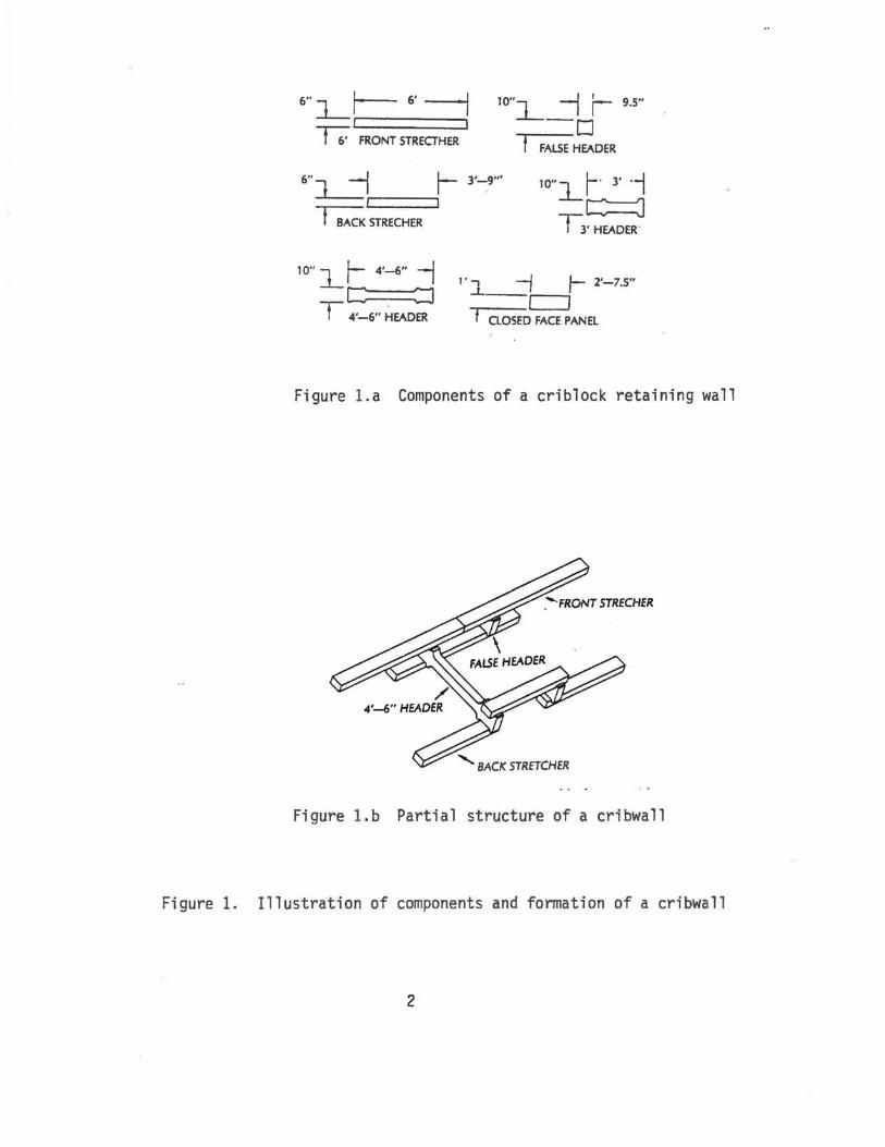
A criblock retaining wall is basically a gravity-type retaining
structure with a face consisting of a grid of precast reinforced concrete
members, as shown in Figure 1. The face is generally inclined at a slope of
four vertical to one horizontal (unless otherwise specified). Horizontal
members of such a grid are termed "front strechers". Where non-standard
I
6"~r- 6'--1 I I
lO"L --j r- 9.5"
-0 -r; FRONT STRECTHER f FALSE HEADER
6" -I r- 3'-9'"
J c=.~ lO"lr-' 3' '-1 c:=::J f BACK STRECHER
10"l.t- 4'-6" --I C ::J
T 4'-6" HEADER
T3' HEADER
1 • .., -j t- 2'-7.5" ..L_-C]
t CLOSED FACE PANEL
Figure l .a Components of a criblock retaining wall
......... BACK STRETCHER
Figure l .b Partial structure of a cribwall
Figure 1. Il lustration of components and formation of a cribwall
2

stretcher lengths are required to complete the end of a wall, they are
termed "closers". The face members are connected by transverse members
termed "headers" to a similar grid of "back stretchers" parallel to the face
and located so that the overall thickness of the wall is not less than three
feet. To complete the wall, some additional spacers, termed false headers,
may also be used if the system requires it. Headers are to be perpendicular
to the face of the wall.
B. History of Criblock Retaining Walls
The criblock retaining structures were introduced to the United states
over a decade ago. Europe has played a bigger role in developing this
technology, but the first documented case history goes back to 1966 1 in
Australia. The literature obtained on this case history indicated that the
first wall was built in Australia and it consisted of concrete panels to
complete the wall.
During the past two decades, the criblock idea has been used to build
various retaining structures utilizing various elements such as concrete
panels, treated wood members, or used tires. The American Wood Preservers
Institute reports of another project2 which consisted of building a 22 foot
high retaining structure with treated wood members bolted together and
filled with rock or other suitable material. The Institute of Civil
Engineers also reports of a case history3 where used tires were used to
build a crib wall 40 M long and 3.7 M high to form a flat parking area.
The unusual construction detail of the wall concerns the use of some 4,000
used tires, which were laid by five men and two mechanics at a rate of up to
3

360 tires per 8 hour day. First, a layer of tires was placed to give
maximum interlock with the previous layer, using link bars where necessary.
Then, a crawler loader placed shale and siltstone fill over the tires, and
workers shovelled the fill into the tires. Finally, a Bomag vibrating
roller compacted and leveled the fill. The sequence was then repeated for
each layer of tires.
The use of criblock retaining walls using concrete panels has become
more popular, and it has found many commercial applications. Some of these
commercial applications include:
a. Highway Applications
b. Slot-cut Walls
c. Sound Barrier
d. Multiple Depth construction/and
e. Landscaping.
III. PROJECT LOCATION AND GEOLOGY
The Project BRO 0057(2) was located on county Road 17, in Pitkin
County, as shown in Figure 2. Construction during this project consisted of
replacing the Gerbiz bridge across the Roaring Fork River, northwest of
Woody Creek. The new bridge replaced the old bridge about 20 feet
upstream, as shown in Figure 3.
Chen and Associates was selected to perform the geological study of
the site and make recommendations on the types of foundations appropriate
4

STATE DEPARTMENT OF HIGHWAYS DIVISION OF HIGHWAYS-STATE OF COLORADO
PLAN AND PROFILE OF PROPOSED
FEDERAL AID PROJECT NO. BRO·QO?1(1)
COUNTY ROAD NO.\l PITKIN COUNTY
ItAc.n", Cltog ...........
011 ........ 1....20 "
~ MGII,. (:::: : ,I: ;~ =-:~ ..... ~ UfIIC _ ,...,.., ,. 8JIOwIt AI GAoI«. IW.,..& .....
__ 0"'1111 STA o.QO
.. .
Figure 2. geological location of project BRO 0057(2)
5

COUNTY ROAD
16
PROPOSE!) \ \
Cl OF NEW ~
BRIDGE \
FLOW /
ROARING FORK
RIVER
.
\ ' \
( = 20'
\
Figure 3. Skematic of the location of the new bridge relative to the old one
6

for this project.
The results of the geological study indicated that the subsurface
conditions encountered at the site consisted of a variable depth of man
placed fill overlying natural gravels and cobbles at the east abutment
boring and sandstone bedrock at the west abutment boring. Ground water
was encountered at the river elevation in the boring near the east abutment.
Based on the laboratory testings and the field observations, it was
recommended to use spread footing foundations for both abutments to support
the bridge structure. It was also calculated that the spread footings may
undergo a total settlement of one inch or less which was categorized as
being acceptable.
Based on the above field investigation and the request of the county,
it was decided to build two criblock retaining walls to retain the soil on
both ends of the bridge and provide an aesthetically desirable look for the
environment.
IV. CONSTRUCTION
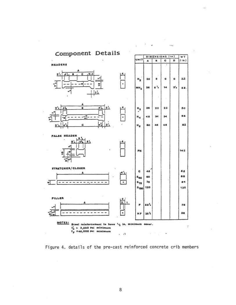
For this project, the two criblock retaining walls were designed by
"retention engineering" and they were constructed using the pre-cast
reinforced concrete crib members as shown in Figure 4.
The wall on the east end of the river was designed to be 95 feet long
and 10 feet high. The segment on the west end of the river was much smaller
7
component Details DI"E"~IO"~ lin I
UNIT ..
"z :Z0
-":II H
":II :III . "4 "'. ". eo
PH
ITMTCKK"/ CLan"
t A I C 4.'
Sea eo
~ 1- - - - - - - - -.- - - - -I S7. 1'.
$,. 120
PILLa"
.. I A I "~I-------------I
P •• J~
"" u\
!2!.!!.:. .,_1 roinforca_nc I. ha.. 1':1 In. mlnln .... n _.r. r~ :; :1,2$0 •• 1 mIni ........ 'It =40,000 .. 1 ",Ift.", .. m
. "
• C D
• 0 0
.7. 14 2 1•
22 22
~ :M
- 41
WT
1111'
:s.:z
•••
So
'1
82
142
'. •• 84
1:110
7.
~.
Figure 4. details of the pre-cast reinforced concrete crib members
8

in length, but was designed to be a few feet higher compared to the one on
the opposite side. Figure 5 shows the details of the cribwa11s for this
project.
The construction of a cribwa11 is basically an easy process. The
originators of cribwa1ls would like to think of this process as a "one man,
one block" operation. The most important criteria to consider is the
preparation of the cribwa1l base. No special concrete slabs are required,
but the base needs to be cleaned and perfectly leveled to the required grade
so that the first cribwall components are placed on the top of a uniform
and firm base providing an adequate foundation for the rest of the wall.
To begin the wall construction, an appropriate amount of excavation
was performed on both ends of the bridge for placement of the crib10ck
components. Excavation on the west end of the river was carried out with
an extreme amount of difficulty due to the presence of sandstone near this
end of the bridge.
The base of the walls was cleaned and compacted using vibratory hand
compactors as shown in Figure 6. Additional soil, gravel, or a mixture was
placed and compacted to create the four vertical to one horizontal slope at
the wall base. During this project, four to five inches of sandy gravel
was used as base material at the bottom of the walls due to the high ground
water elevation encountered at the river level. Figure 7 shows the sa~dy
gravel blanket prior to construction of the walls.
Once the base preparation was completed, the rest of the wall was
9

'LlyATION
.'.
.ll.A.IL
~'i i i.. ' . J
:~ ~:'''1: cu~. It It
'. REVATION to
Figure 5.
• a. ~ ..
DRAWINGS NOT TO SCALE
_ ....... '--r ~- '-"~': ....
...... -..
.. I--.~r ..... _ .. '
- T-:=.=-.... -r ...... -, '" -.-. .u~ .................. _~ ...... --............... - .... ~---- ....... .. :-.:::. -:-::. -:.=.::.:..--:::= ==-=- 1 --~~
...... ' •• e ...... ....................... - .... _ ....... .. ....... _ .... M ....... !I .... _ .... .
UIYD ......
Details of the cribwa l ls in project BRO 0057(2)
10
."'

Figure 6.
Figure 7.
'.,
.I"
" .. ... .... : • .J ..... ',.,.. .~
" "
" . ( ~:. '<'>~ I ~. . .1. .... ..
. ,./ ~ . ~.
Foundation preparation for the east wall
"
Placement of granular soil at the base of the wall
11

erected without much difficulty. The cribwall members were handled by the
laborers present at the site by simply stacking them on top of one another
and making sure the alignment and the required grade were preserved.
The first course of cribwall units was the front and back stretchers
(or closers). This step was carefully done to ensure firm bedding against
the base soils. Figure ~ shows the placement of front and back stretchers
at the east end of the large cribwall.
The cribwall cells were placed in horizontal lifts and they were
backfilled after placement of maximum three lifts. The backfill soils
consisted of granular soils with a large percentage of gravel and free from
organic material. The backfilling was accomplished by a front loader
slowly pouring the backfill soil into the completed cribwall cells.
The next step was to compact the backfill soil contained in the cells.
This was done by using a special hand-held vibrator small enough to be
placed inside the cells and provide 85 percent or higher of AASHTO T-99
compaction at optimum moisture content. The compaction effort was performed
for each foot of backfill soil which was poured into the cribwall cells.
Figures 9 to 16 show the progress of the cribwall construction on the east
end of the river.
The construction of the cribwalls followed a simple procedure and
required no heavy equipment for completion of the walls. The crib members
consisted of precast, reinforced concrete elements light enough to be
handled by one man. The base of the walls required no special treatment
12

Figure 8.
Figure 9.
.,. . :.: ' . ";. ~ "
.~ ' "... ~.;" • "11"'+.' , < ..
.t:t. ." .• ~
Placement of the front and back strechers for the east wa 11
Close-up view of the concrete cribwal l components
13

Figure 10 construction of the east wall in progress
Figure 11 contrast in elevation at different lacations of the east wal l
14

Figure 12 pregress of the east cribwall
Figure 13 compaction of the soil inside the concrete blocks
15

Figure 14.
Figure 15.
completed east cribwall
completed west cribwall
16

Figure 16 view of the completed structures on project BRO 0057(2)
17

except leveling and placing some granular soils to act as a drainage
blanket during the high ground water table.
The crib members were handled by the laborers present on the job
site. Each laborer could carry one element to its designated location
where qualified personnel were building the crib cells by stacking them
on top of each other in an orderly manner. The rest was to level,
maintain the grade, backfill, and compact the soils according to the
provided specifications.
No major difficulties were encountered during the construction, and
the walls were completed in less than 10 working days.
The walls were estimated to cost $15 per square foot of wall face,
but they were bid at $17 per square foot. Based on our experience, this
cost seemed to be competitive with the costs of other retaining wall
systems. Therefore, the construction of the concrete criblock retaining
walls was approved on an experimental basis, and both walls were monitored
to determine their long-term performances.
v. MONITORING AND DATA ANALYSES
After completion of the walls, one station on the west wall and three
stations on the east wall were selected for monitoring of the future wall
settlements. At each station, three points on the top, middle, and lower
part of the wall were selected for monitoring as shown in Figure 17.
18

lOS-
\00
's-~.
is I
\\0
1"5
100
'15
I. ~ ~ -I- ~
"I '" 1 ___ . ____ ~ .. __ ..
zA
i EAsr-_iI
.!Lt4L~ I!:
_'!'·-'1.?':-{~
.. .., 1-.... - .. __ _ _ _
I JA
3~
3C
In ~ -I...,
- __ . I
Figure 17. elevation points on the east and west walls
19
I:

All points were monitored for vertical settlement using the standard
survey techniques and the results are presented in Table 1.
The survey results indicated that during the 14 months following the
construction of the walls, a maximum of 0.05 and 0.06 feet of settlements
had occurred on the east and west walls, respectively. These settlements
were considered to be negligible and tolerable by the walls.
The crib members at the face of the walls (front stretchers)
appeared to be in good shape except for two locations where they had lost
some alignment due to local settlement and adjustment of the backfill
soils behind the walls. This can be seen in Figure~. These local
realignments occurred immediately after the walls were completed, and
they did not improve during the 14 months monitoring period.
VI. CONCLUSIONS
a. The criblock retaining walls are easy to build, and they require
no special heavy equipment for completion of walls.
b. The cost of a criblock retaining wall is competitive with the
other retaining walls built by the CDOH.
c. Crib lock retaining walls can be aesthetically pleasing_ If the
backfill soil is appropriate, some local plants and vegetation can
be planted onto the cells at the front face to further improve the
image of the concrete blocks.

CRIBWAll SETTLEMENT DATA PROJECT BRO 0057(2)
DATE STATION 1+47 STATION 3+03 STATION 3+52 STATION 3+98
1A 1B 1C 2A 2B 2C 3A 3B 3C 4A 4B 4C
05/02/89 106.81 102.77 98.73 101.18 96.17 92.14 100.23 96.21 93.22 99.20 96.19 93.18 05/18/89 106.80 102.76 98.72 101.16 96.16 92.13 100.23 96.17 93.20 99.20 96.17 93.15 05/31/89 106.81 102.77 98.73 101.20 96.16 92.12 100.23 96.20 93.20 99.19 96.18 93.16 07/25/90 106.75 102.72 98.67 101.18 96.14 92.12 100.22 96.19 93.19 99.16 96.14 93.13
SETTLEMEN 0.06 0.05 0.06 0 0.03 0.02 0.01 0.02 0.03 0.04 0.05 0.05 N t->
TABLE 1. THE RESULTS OF THE SURVEY DATA

: ~ (
Figure 18 separation of the concrete blocks due to settelment of the foundation soils
22

VII. IMPLEMENTATION
Based on the experienced gained during this study, the cribwall
system is Buitable where the subsoils beneath the wall are stable and will
not experience significant settlement due to the weight of the wall.
Therefore, this retaining wall system should be included as an alternative
design in the CDOH Retaining Wall selection process.
23

BIBLIOGRAPHY
1. Precast Concrete CriQ Type Gravity Retaining Walls; Goble, Jr. Australian Road Research Board Conference Proc. 1966 Vol 3, Part 2, Paper No. 232, PP 1593-1601.
2. American Wood Preservers Institute; 1651 Old Meadow Road; McLean, Virginia 22101 Report No. HD2 Date: Jan. 1972.
3. Institution of civil Engineers; Now Civil Engineer N239; Apr. 1977, 18PP, 1 Fig., 2 Photo
4. The Stabilizing of Steep Slopes Using Crib Walls; Transport and Road Research Laboratory; TRRL Translation N3407, Nov. 1987, 37P, 6 Ref.
5. Experimental Tied Back Crib WQall With salvaged Guardrail Facing; California Department of Transportation Office of Sacramento, California; Aug. 1984, Final Report English, Report No. FHWA/CA/TL-84/18, Contract No.: R81TL23.
6. Timber Crib Instrumentation Study; Idaho University, College of Engineering, Moscow, Idaho 83843; June 1974, 60 PP; Schuster, RL; Sack, RL; Jones, WV.
24