momommhhmhhlo ehhmmhhmmmu - defense technical … · momommhhmhhlo ehhmmhhmmmu. 1111112 *2 iou! t1....
TRANSCRIPT

-Ri32 619 AN ANALYSIS OF THE ECONOMIC IMPACT OF THE AN/RPS 134 11FLR (FORWARD LOOKIN..(U) NAVAL POSTGRADUATE SCHOOL
RSIFE MONTEREY CA R E DUNN DEC 84F/179N
momommhhmhhloEhhmmhhmmmu

1111112 *2
IOU!
t1.
1*1 lll_ -
IIIIl ____
II I 2 5 III~ 11111I

Ul) NAVAL POSTGRADUATE SCHOOLMonterey, California
DTICSELECTEAPR 19 1985 f
THESISAN ANALYSIS OF THE
ECONOMIC IMPACT OF THE AN/APS-l34 FLAPRETROFIT ON COAST GUARD HC-l30 AIRCRAFT
by S b
Robert Earl Dunn
December 19814
Thesis Advisor Paul M. Carrick
Approved for public release; distributilon un'Limittci.
85- 03 29 041

SECURITY CLASSIFICATION OF THIS PAGE (W~ten Data Entered) _
REPORT DOCUMENTATION PAGE READ INSTRUCTIONSBEFORE COMPLETING FORM
1REPORT NUMBER 2. G VT ACCESSION NO.3 RECIPIENT'S CATALOG NUMBER
4. TITLE (mod Subtitle) S. TYPE OF REPORT & PERIOD COVERED 5An Analysis of the Economic Impact Master's Thesisof the AN/APS-134 FLAR Retrofit on December 1904•Coast Guard HC-130 Aircraft 6. PERFORMING ORG. REPORT NUMBER
7. AUTHOR(#) S. CONTRACT OR GRANT NUMBER(I)
Robert Earl Dunn
9. PERFORMING ORGANIZATION NAME AND ADDRESS 10. PROGRAM ELEMENT. PROJECT, TASKAREA & WORK UNIT NUMBERSNaval Postgraduate SchoolMonterey, California 93943
11. CONTROLLING OFFICE NAME AND ADDRESS 12. REPORT DATE
Naval Postgraduate School December 1984Monterey, California 93943 13. NUMBER OF PAGES
10214. MONITORING AGENCY NAME & ADDRESS(Illdlfferent from Conttolling Olflce) IS. SECURITY CLASS. (of this report)
S"lSa. DECLASSIFICATION/ DOWNGRADING
SCHEDULE
16. DISTRIBUTION STATEMENT (of this Report)
Approved for public release; distribution unlimited.
S
17. DISTRIBUTION STATEMENT (of the abstract entered In Block 20, if different from Report)
ii
IS. SUPPLEMENTARY NOTES
19. KEY WORDS (Continue on reerse side if necessary and Identify by block number)
Coast Guard FLAR, AN/APS-134, HC-130 Aircraft
20. ABSTRACT (Continue on reverse side If necessary and Identify by block number)
Concern over the growing drug smuggling problem and improvednational defense capability are manifest in the need for a newforward looking airborne radar (FLAP) for Coast Guard HC-130aircraft, with a capability of detecting a target of 1 squaremeter radar cro;s section. This thesis reexamines the analysisthat selected t' AN/APS-134 FLAP over other contenders basedon mission need, radar performance and life cycle cost criteria.
DD JAN3 1473 EDITION OF I NOV 65 IS OBSOLETE
S N 0102- LF- 014- 6601 1 SECURITY CLASSIFICATION OF THIS PAGE (When Date Entered)
• . : : :.: .-. .. -:. ... .-- . - . ::. . .: - .. . . . . . . - - . - : . . - -. . _- - - . _. - ,

SaCUNIrY CLASSIVICATION OR TIS IWAGI (ft Doe Kneatm
This thesis presents a better understanding of the resulting
HC-130 force structure based on the impact of FLAP technology.
Accession For
K 7J3
AvailabilitY CdOc.sjAvai1 and/or
iDist~ Special
D0G
NO 0102- LF- 014- 6601
2 SECUORITY CLASSIFICATION OR THI1S PWAOE(WMe Data Entered)
..........................................................

75
Approved for public release; distribution unlimited.
An Analysis of theEconomic Tmpact of the AN/APS-134 FLARRetrofit on Coast Guard HC-130 Aircraft
by
Robert Earl DunnLieutenant, United States Coast GuardB.S., Kansas State University, 1972
Submitted in partial fulfillment of therequirements for the degree of
MASTER OF SCIENCE IN MANAGEMENT
from the
NAVAL POSTGRADUATE SCHOOL
December 1984
Author: ,, vRobert E. Dunn
Approved by: . C /1?. "J..... jPaul M. Cri'.T Ad vi so r
R. Neagle orrest, Second Reader "''
Willis R. Greer, Chairman, epartment ofAdministrative Sciences
_SKneale T." Marshal'l, 49F 6( InfTormation
and Policy Scll s .i '.
a I
. - . ~ a.. .. -,, ,---. ..-. . . . . . . ..I
i l , ' . . . ... . . . . . .. .
ABSTRACT
Concern over the growing drug smuggling problem and
improved national defense capability are manifest in the
need for a new forward looking airborne radar (FLAR) for
Coast Guard HC-130 aircraft, with a capability of detecting
a target of 1 square meter radar cross section. This thesis
reexamines the analysis that selected the AN/APz-I34 FLAR
over other contenders based on mission need, radar
performance and life cycle cost criteria. This thesis
presents a better understanding of the resultinq HC-10
force structure based on the impact of FLAR technology.
4
. . . *~ ... . . .
* .. . . . . . . . .. . . . . . . . . . . . . . . . . . . . . . .
*,.• -' . • ,
TABLE OF CONTENTS
I. INMTRODUCTION------------------------------------- 7
A. THE PROBLEM------------------------------
B. INTENT-------------------------------------- 9
C. METHODOLOGY--------------------------------l10
II. BACKGROUND-------------------------------------- 13
A. HISTORICAL MISSION OVERVIEW--------------13
B. AVIATION SUPPORT------------------------- 14
C. MISSION ANALYSIS-------------------------- 1P
1. Search and Rescue (SAP)------------ 19
2. Enforcement of Laws and-------------22Treaties (ELT)
3. Military Operations---------------- 25
4. Ice Operations--------------------- 26
D. SEARCH THEORY---------------------------- 26
E. LIFE CYCLE COST--------------------------- 41
F. AN/APS-134 BUY DECISION----------------- 41
III-ANALYSIS-------------------------------------- 48
A. MISSION---------------------------------- 4P
1. Base Line Requirements---------------4q
2. Search and Rescue Requirements --- r(
3. Enforcement of Laws and Treaties - 9PRequirements
4. Military Requirements-------------- q
5
5. Mission Requirements Summary -----
B. PERFORMANCE ----------------------------
1. Performance Comparison ------------ 6
2. Performance Summary -------------- 57
C. COST ---------------------------------- 62
1. FLAR Equipped LRS Costs ---------- 63
D. COST EFFECTIVENESS SUMMARY 6------------
IV. CONCLUSIONS AND RCOMMENDATIONS ------------- 74
APPENDIX A. TOTAL LRS EMPLOYMENT HOUR -------------- 76REQUIREMENTS FY87-91
APPENDIX B. SEARCH PATTERNS ------------------------ 7
APPENDIX C. SAMPLE RADAR CROSS SECTIONS -------------
APPENDIX D. FLAR TECHNICAL DATA ------------------ ql
APPENDIX E. SEARCH AND RESCUE ASSISTANCE REPORT --- PS
AND PARTIAL KEY -
APPENDIX F. SEA STATE SUMMARY -- ------------------- 88
APPENDIX G. SUMMARIZED COST DATA; DEVELOPMENT ------ 9
PLAN FOR C-130 AIRCRAFT RADARRETROFIT
APPENDIX H. SUMMARIZED COST DATA; BUDGET ---------- 01
DIVISION, COAST GUARD HEADQUARTERS
APPENDIX I. LRS TOTAL COST TABLE, BY FLAR --------- 93
SYSTEM FOR FY87-91
LIST OF REFERENCES ---------------------------------- 98
BIBLIOGRAPHY I----------------------------------------1
INITIAL DISTRIBUTION LIST -----------------------------102
•--.-.-.....................................-.-...- .......--.'---.V . "..-........... . , ...

-T, T~ N7pon[r)F7 T
~. TH' PP )!ltFA
\' tional d7-efense and law and or der re too m-j or
national issues that have been subject to considerable
debate and have experienced increased national concern
during the late 1 7 Pls and early laqfs. Fol lowinq t~'e
Iranian hostage situation and other events in the Middle
East, the capability of the United States to quickly project
its military power to any spot on the globe and carry out
sustained conventional warfare fell into some question.
Likewise, concern has grown over the expandinq illicit drug
problem in the United States, its adverse impact on all
facets of law and order and on the scope of efforts underway
to combat it.
This increased concern over national security and drua
abuse in the United States has been translated into tangible
commitments through the reordering of national budget
priorities. The reallocation of scarce resources durinq the
first half of this decade was founded upon the belief that
specific military preparedness and readiness capabilities,
and drug interdiction goals could be reached through
increased funding of the responsible agencies and their
programs. It has been the responsibility of each agency to
formulate the specific programs designed to meet articulated
national goals in the most cost effective manner possible.
7
fu... E

The United States Coast Guard has statutory
responsibility as both the nation's primary maritime law
enforcement agency and as one of this country's five armed S
services. While enforcement of laws and treaties and
military preparedness are, but only two, of a myriad of
humanitarian, regulatory and service missions performed by 6
the Coast Guard, they do represent two of the largest and
oldest traditional missions.
The constant challenges that face the Coast Guard in
mission program management are, of course, parallel to those
met by most government agencies once a national goal has
been identified and a willingness to commit scarce resources
has been uiade. First, a strategy and plan must be
formulated to reach the goal. Second, the necessary
organization needs to be created that will be able to 0
realize the goal. This includes establishing the command
and control structure, staffing all required billets with
fully trained and motivated personnel and equippinq the
organization with the materials and equipment needed For
full scale operations. Third, as organizational units
conduct their operations in oursuit of the aqencies assiqned
goals, the agency must evaluate results against taskinn and
adjust existing agency plans and assets while evaluatinn the
possible benefits of alternate strategies, organization,
hardware and technology.
"R
. .. .°
......- - . .. . - .. . . -.. . . . . . . ..- " .'.".- . ..- . -.. , .-. - -.-- ', . i'-' -. .-',. -L- -< .---- - ,< . o . . . -

Having long standing mission tasking in the areas of law
enforcement and military preparedness, the Coast Guard has
ongoing programs addressing each already in place. The
impact of intensified national commitment to these missions
has meant additional funling to reach higher levels of -ruq
interdiction and increased levels of military capability and
readiness primarily through the use of new or improved
technology.
Typical of the various projects now underway to address
upgraded tasking for illicit drug interdiction and improved
military readiness, is the ongoing acquisition of the
AN/APS-134 search radar for Coast Guard long range search
(LRS) aircraft. This radar, when retrofit on the existing
Coast Guard HC-130 fleet, is designed to greatly increase
the aircraft's capability to locate surface targets in the
maritime environment. In turn, other resources will then be
able to board and seize the target, in case of illicit drua-
trafficking, or engage and defeat it, as in the anti-
submarine military mission.
B. INTENT
Although a project to retrofit the Coast Guard HC-1 VI
fleet with the AN/APS-134 search radar is already underway,
the purpose of this thesis is to reevaluate the premise that
the original AN/APS-59B search radar was no longer . -
economically and technically adequate to meet now and
9
_- ,_- - .,.. .. ... ... ... .m - m~rm m ' "l' mm~w am- J mm " ,

growing Coast Guard mission goals and objectives, within the
economic context of life cycle cost effectiveness. The
Development Plan for C-131 Aircraft Radar Retrofit, (Ref 1]
prepared by the Naval Air Development Center, makes
technical evaluations and comparisons of all logical
replacement contenders and presents a limited life cycle
cost analysis of the AN/APS-134 radar. However, no attempt
has been made to provide the decision maker with a life
cycle cost comparison based on a performance standard, or to
address the impact of each alternative on force structure.
This thesis will attempt to address the radar question from
the economic perspective and provide the decision maker with 0
the necessary information upon which to make a choice.
C. METHODOLOGY .
The basic background material reviewed on Coast Guard
programs and goals came from both special and periodic
strategic planning documents. The Coast Guard Roles and
Missions Study, [Ref 21 completed in 1982, provided an
excellent strategic overview of how the Coast Guard expects
to handle anticipated tasking over the next twenty-five
years. The Operating Program Plans for each major mission
(law enforcement, search and rescue, etc.) transforms
strategic thinking into five year olans that are updated
annually. All operating plan resource requests are
integrated into major Coast Guard resource renui r-ments
e
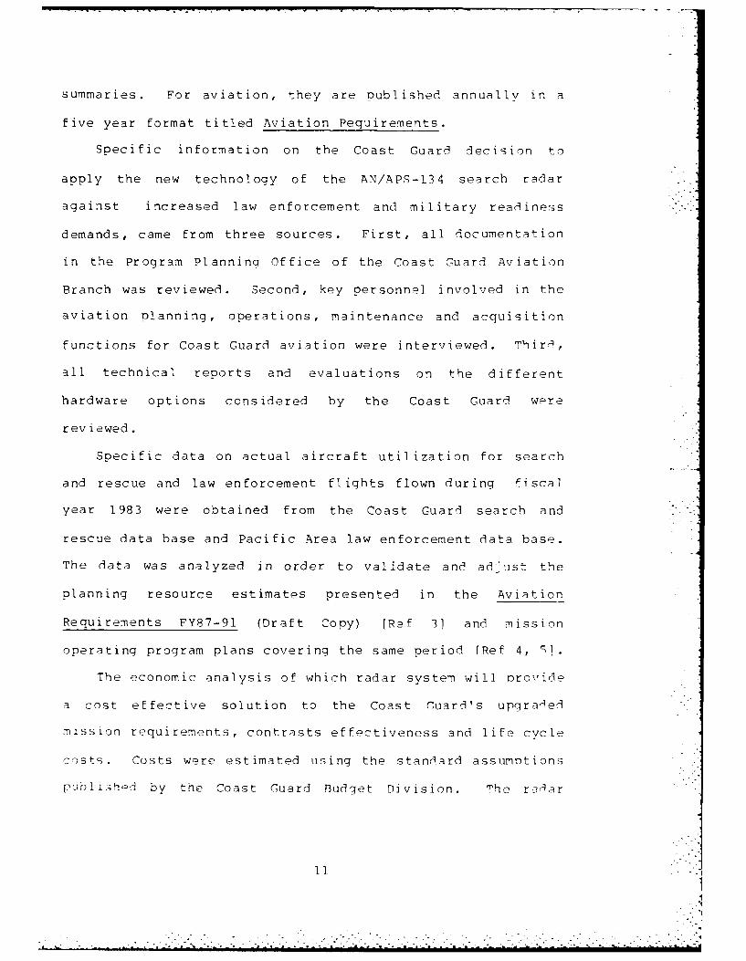
summaries. For aviation, they are oublished annually in a
five year format titled Aviation Pequirements.
Specific information on the Coast Guard decision to
apply the new technology of the AN/APS-134 search radar
against increased law enforcement and military readiness
demands, came from three sources. First, all documentation
in the Program Planninq Office of the Coast Guard Aviation
Branch was reviewed. Second, key personnel involved in the
aviation planning, operations, maintenance and acquisition
functions for Coast Guard aviation were interviewed. Third,
all technical reports and evaluations on the different
hardware options considered by the Coast Guard were
reviewed.
Specific data on actual aircraft utilization for search
and rescue and law enforcement flights flown during fiscal
year 1983 were obtained from the Coast Guard search and
rescue data base and Pacific Area law enforcement data base.
The data was analyzed in order to validate and adjust the
planning resource estimates presented in the Aviation
Requirements FY87-91 (Draft Copy) [Ref 3] and mission
operating program plans covering the same period fRef 4, S].
The economic analysis of which radar system will orovide
a cost effective solution to the Coast Guard's upgraled
mission requirements, contrasts effectiveness and life cycle
costs. Costs were estimated using the standard assumotions
publ ish-I by the Coast Guard Budget Division. The raaar
IlI
. .. ..
.. ,:.- •,., ,,. L "",-- b,. .. . , -..- . . ..-. .- .,- .- . .,.,",
", " - " : '"" = : " : " "" "
'" " ..
most fishing activity takes place, and to cover closed or
restricted areas.
The illegal alien problem is connected primarily to
Haiti and is small relative to the drug interdiction and
fisheries missions. Here, the approaches to Florida from
Haiti are patrolled to interdict illeqal aliens attemotinci
to enter the Uniter States in small, usually unsafe, wooden
vessels. This mission is done in conjunction with Caribbean
drug interdiction operations.
It should be noted that the exoansion of the druc
interdiction mission is the largest driving corce in
creating the LRS shortage, as depicted in Aopendix A,
Summary of Aircraft Requirements FYP7-91.
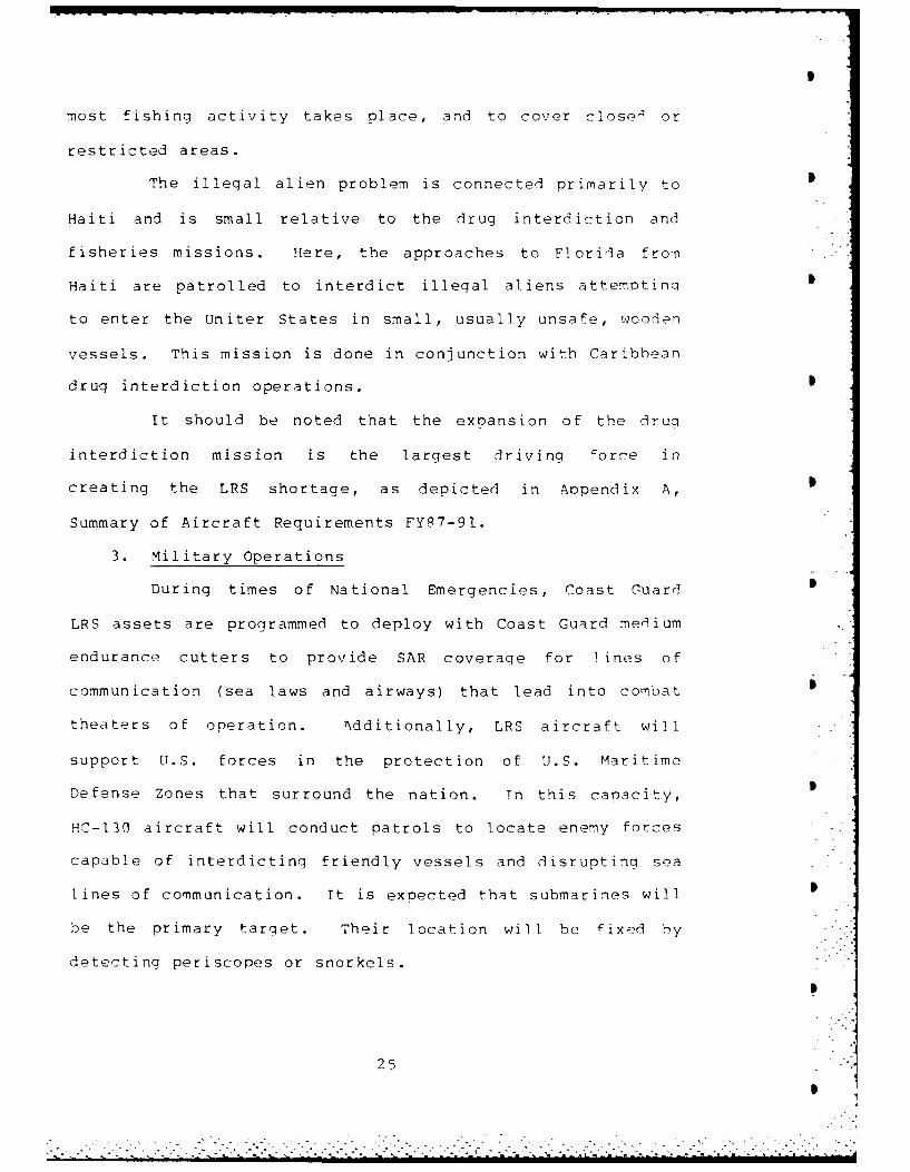
3. Military Operations
During times of National Emergencies, Coast Guard
LRS assets are programmed to deploy with Coast Guard medium
endurance cutters to provide SAR coveraqe for lines of
communication (sea laws and airways) that lead into combat
theaters of operation. Additionally, LRS aircraft wil1
support U.S. forces in the protection of U.S. Maritime
Defense Zones that surround the nation. Tn this canacity,
HC-133 aircraft will conduct patrols to locate enemy forces
capable of interdicting friendly vessels and disrupting sea
lines of communication. It is expected that submarines will 0
be the primary tarqet. Their location will be fixed by
detecting periscopes or snorkels.
2
25"
S
-. . . . . . . .. . . .
- - - - - . .. ., . .

transporter of narcotics from Columbia to II.S. Coastal
waters. The "mothership" is 64-310 feet in length and is
typically a large fishing vessel or small coastal freiohter.
The "contact" boat is a small boat 16-30 feet in length that
transports the contraband from the "mothership" to shore.
These vessels are recreational vessels or small fishing
vessels. Finally, some large sailing and fishing vessels,
from 45-90 feet in length, make the entire trio from South
America to the United States. These vessels tend to stay S
closer to the coast (10q miles) and unload in secluded areas
at night.
Fisheries law enforcement takes place within the ?2q
mile Fisheries Conservation Management Areas (FCMA) adjacent
to the continental United States, Alaska, Hawaii and the
Pacific Island Territories of the United States. Within the
FCMA, all foreign fishinq vessels must be license9 for
fishing by the United States, must abide by U. .
regulations, and submit to inspection. Purther, limited 0
regulation is conducted for U.S. vessels i nvolve i n
critical fisheries such as salmon.
The LRS role in fisheries enforcement is to natro 1
FCMA fishing grounds and locate vessels in violItion of
season and position regulations, and to locate vessels for
periodic boarding by Coast Guard and Mational Marine 0
Fisheries boarding teams. The mission profile for
fisheries' patrols is to follow the 1 0 fathom curve, wh-r,
24 .- ", .
2 . .'
*

transportat ion.
Coast Guard interdiction rates for the early 1980s against
seaborne smuggling is estimated at between 15-20%.
The Caribbean and off Baja, Mexico are the two
primary areas that anti-smuggling efforts are concentrated.
Due to the geography of Columbia, most illicit narcotics
transit the Caribbean to the Southeastern United qtates.
The islands and corresponding oasses (Windward, Yucatan,
Mona, Anegada, etc.) allow the concentration of friendly
forces at "choke points". In the Pacific, geography has
provided no advantages. The West Coast of Columbia is
mountainous and costs the smuggler more to ship from, but
there are no natural barriers that create choke points.
In the Caribbean, LRS aircraft directly supportp
Coast Guard cutters underway in the passes. The aircraft
serve as the eyes of the fleet in locating suspect vessels,
and the cutters provide the boarding capability. Typically,
barrier patrols are flown.
In the Pacific, LRS aircraft frequently fly without
dedicated vessel support due to the vast area through which p
a smuggler can approach the United States. LRS sorties
usually have little intelligence data to work from and are
more random in nature.
Smuggling vessels fall into three broad catagories.
The primary target is the "mothership" and serves as a major
23

a distress is not known. Typically, these sorties are in
response to overdue vessels or when an immediate rpsnonse
flight is unable to locate a vessel in distress or all its
survivors. These missions involve extensive preflight
planning and rely primarily on the LRS crew as vis .-ua,
observers to locate small targets like wreckage, rafts or
people in the water.
2. Enforcement of Laws and Treaties (ELT)
A growing program, [RS sorties have been flown in
support of three main enforcement efforts over the past few
years: narcotics, fisheries, and illegal aliens. \pDendix
A projects that 10,117 hours for 39% of FY87 LPS hours and
13,758 hours for 47% of FY91 LRS hours will be flown for the
ELT program.
Interdiction of narcotics smugglinq vessels
represents the largest investment of Coast Guard LEF effort.
The Enforcement of Laws and Treaties Operating Program Plan
FY87-91 [Ref 12] summarizes the scope of the narcotic
problem as:
Ten to fifteen thousand meteric tons of marijuanaare supplied to the U.S. market from foreion sourcesannually. Of this, approximately 6,000-9,q(V tonsof marijuana are shipped by sea. Columbia accountsfor approximately 75% of all marijuana shipped tothe U.S. Given the enormousprofits to be made fromsmuggling marijuana and other druqs into the UnitedStates a large rate of seizure is necessary in orderto have a deterrent effect. A 70% level ofinterdiction may force smugglers to use othertechniques such as increased aircraft or overland
22
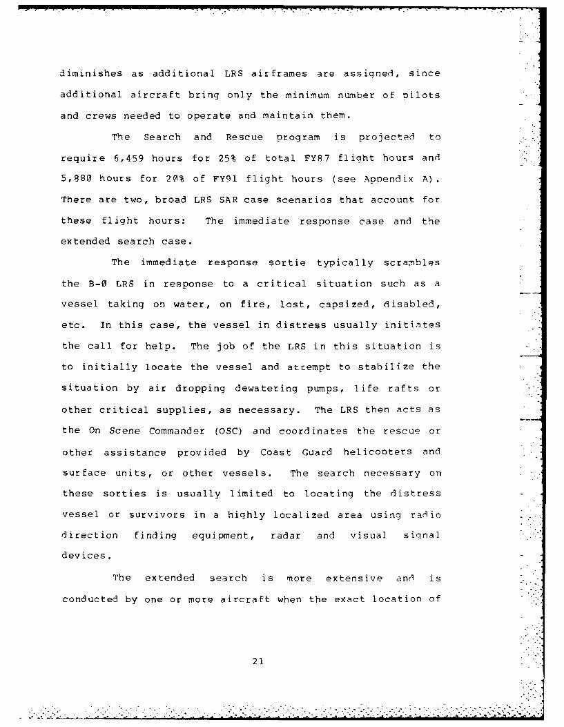
diminishes as additional LRS airframes are assigned, since
additional aircraft bring only the minimum number of pilots
and crews needed to operate and maintain them.
The Search and Rescue program is projected to
require 6,459 hours for 25% of total FY87 flight hours and
5,880 hours for 20% of FY91 flight hours (see Appendix A).
There are two, broad LRS SAR case scenarios that account for
these flight hours: The immediate response case and the
extended search case.
The immediate response sortie typically scrambles
the B-0 LRS in response to a critical situation such as a
vessel taking on water, on fire, lost, capsized, disabled,
etc. In this case, the vessel in distress usually initiates
the call for help. The job of the LRS in this situation is
to initially locate the vessel and attempt to stabilize the
situation by air dropping dewatering pumps, life rafts or
other critical supplies, as necessary. The LRS then acts as
the On Scene Commander (OSC) and coordinates the rescue or
other assistance provided by Coast Guard helicopters and
surface units, or other vessels. The search necessary on
these sorties is usually limited to locating the distress
vessel or survivors in a highly localized area using radio
direction finding equipment, radar and visual siqnal
devices.
The extended search is more extensive and is
conducted by one or more aircraft when the exact location of
21
." .--,'. . ." . .. "-" ---.... .- 'am - ..mmdml~k..... . . . . . . . . . . ..... .. .- -

The Search and Rescue program has established a
requirement that each of the five LRS equipped air stations
maintains one "Bravo Zero" (B-QJ) HC-13g aircraft. A B-q LRS
must be capable of being airborne within In minutes of first
notification, or diverted from the local flying area with a
fully qualified SAR crew and ample fuel, if already
airborne. Accordingly, each air station maintains one
"ready" crew and aircraft on alert at all times [Ref 1(].
The impact of B-0 tasking on the standard
utilization rate method of making LRS aircraft assignments
is two fold. First, based on a historically proven "not
operationally ready" (NOR) rate of 29% per HC-131, due to
maintenance, a minimum of three HC-131 aircraft must be
assigned to each LRS station. This must be done to insure
that at least one aircraft is available 98% of the time. As
presented in Table 2, Aviation Requirements PYR7-ql [Ref I11
has computed the probabilities of having at least one
aircraft available based on a 29% NOR rate.
Table 2: Probability of at Least One LRS Available
Number of LRS NOR Rate1 .71n
2 .0163 .976
Second, additional manning is made to meet the demands that
a 24 hour a day, alert requirement creates. This advantaqe
217
"-i ..'o, ..... '-,i-, -.b < -/ .2 . . ].I .-i -. -b % -' '.- --.i. -. <- ., i. i. G . ] -- I-I.. ,... . .. i ....j. . . A..N&.

Although all Coast Guard Mission programs can receive
LRS support, most only require occasional logistics sorties.
The Search and Rescue, Law Enforcement, Military Operations
and Polar/Domestic Ice Operations missions are all programs
that can make the most frequent and extensive use of the 4"-V-
130 as a search platform. Appendix A provides a aeneral
overview of projected flight hour needs by operational
program, as compiled in Aviation Requests FYP7-ql (draft
copy).
Table 1: Standard LRS utilization assignment rates
Projected LRS Hours Airframes0-1800 2
1801-2600 32601-3400 43401-4200 54201-50010 6
1. Search and Rescue (SAR)
The Search and Rescue program is the foundation upon
which Coast Guard aviation is built. While each Coast Guar.l
facility type (i.e. aircraft, cutters, boats) is by
definition and design a multi-mission platform, each
facility type is tied to a primary program sponsor who is
responsible for its basic budget support. For aviation, the
Search and Rescue program is the facility sponsor.
Accordingly, the Search and Rescue program has immense
influence on the quantity, composition and deployment of
aviation resources.
19 . .'.

forward deployment base on a constant basis, using LRS
assets from Clearwater and Elizabeth City.
C. MISSION ANALYSIS
The greatest impact on the design and composition of
Coast Guard aviation is made by the physical limitations
imposed by mission workload demands, scheduled and
unscheduled maintenance, manpower availability and budgetary
restrictions. Maintenance and manpower demands are tied
together by the fact that Coast Guard aircraft are piloted 0
by the air station's officers and are crewed by the
station's maintenance specialists. This "fix'em-fly'em"
concept is economical but can impose limitations ,quring oeak
periods of aircraft utilization.
The flight hour is the basic unit used for planninq,
programming and budgeting. The historically proven .
utilization rate used for LRS planning is 8(C hours ner
year. This factor is applied to each operational HC-I."
aircraft assigned to a field unit. It should be noted that S
of the total FY84 fleet of 22 HC-130s, only IR were
considered as operationally assigned to field units. The
remaining aircraft are spares and allow for fleet rotation
to overhaul or modification facilities. A 25% overload
factor is considered before an additional airframe is
assigned. Table I lists the standard utilization rates used1
to assign aircraft to field units.
18'I
...........................~~~~~~~~~~~ ~ ...............................................
14-4
4Iu
iti

b. Transportation of three oassengers.c. Total radius of action of 75S miles at
30,101 feet.d. Total radius of action of 370 miles at
2,000 feet.e. Transportation of any significant size or
weight of cargo.
4. If any one of the above is expected to beexceeded during a mission, the LRS would berequired.
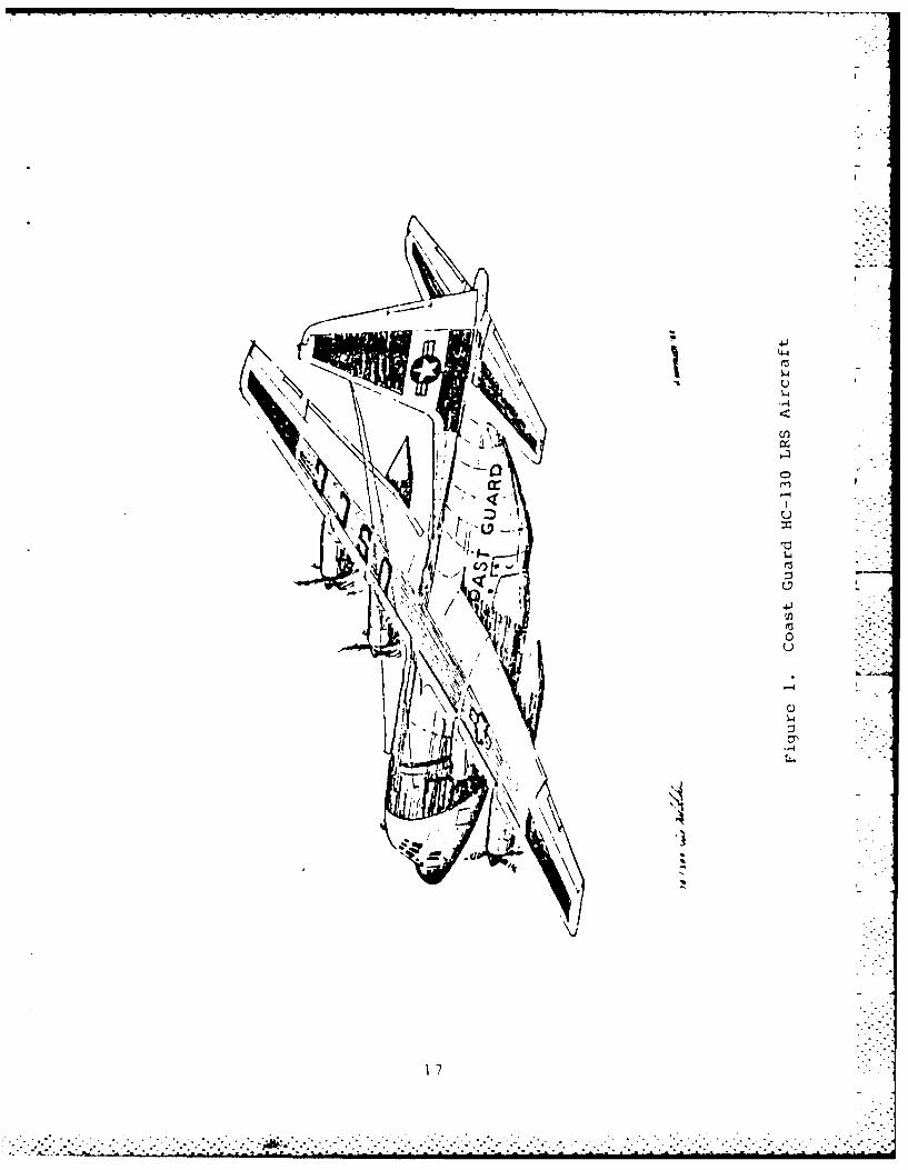
Twenty-two Lockheed HC-13q Hercules aircraft are
currently being used to fill the LRS role. The HC-130 is a
variant of the tough and versatile C-130 turboorop, tactical
airlift aircraft, first developed for the U.S. Air Force in
1955. The Hercules first entered the Coast Guard LRS fleet .
in 1960 and is capable of carrying up to 92 passenqers or
vehicle sized cargos, at a cruise speed of 310 knots at an
altitude up to 33,000 feet (see Figure 1). Long rane -
cruise patrol speed at 1,(0W feet varies between 200 and 234
knots, based on gross weight. Patrol sortie endurance can
be extended from 9 to 12 hours using reduced engine
operations (the HC-130 can patrol using two or three engines
at lighter gross weights when in favorable weather
conditions) and depending on the distance flown at hicrh
altitude to and from the patrol area.
Coast Guard LRS assets are located at five nermanent air
stations: Barbers Point, Hawaii; Kodiak, Alaska;
Sacramento, California; Clearwater, Florida; and Flizabeth
City, North Carolina. Guantanamo Bay, Cuba is used as a
. . . . . . . ... .. .. . ... • . . . . . _ . ... •.. -,. . ......... .. . . . .

Further, the Coast Guard served as the core for a newly
established national Air-Sea Rescue Aqency, monitored
weather and tracked icebergs in the North Atlantic and flew
many of the sea lane control/anti-submarine sorties alona
the Coast of the United States.
Currently, the Coast Guard operates a total of 171 fixed
and rotary wing aircraft from 26 permanent air stations in
support of all Coast Guard mission programs. Different
aircraft types are procured to satisfy each of four distinct
mission need categories. For rotary wing aircraft there are
the Short Range Recovery (SRR) and Medium Range Recovery
(MRR) mission categories, and for fixed wing aircraft there
are the Medium Range Search (MRS) and Long Range Search
(LRS) categories. These catagories are define in the Coast
Guard Aviation Requirements FYR6-90 [Ref 9] planning
document as:
1. An SRR helicopter would be required unless oneof the following was exceeded during a mission.a. Total sortie flight time of 3.0 hours.b. Recovery of three persons from distress.c. Transportation of five passengers.d. Cargo sling capacity of 2,00a pounds.e. Radius of action of 150 nautical miles.
2. If any one of the above is expected to beexceeded during a mission, the MRR helicopterwould be required.
3. An MRS fixed wing aircraft would be requiredunless one of the following was exceeded durinqa mission.a. Total sortie time of four hours.
15
i. i? ,

3. Enforcement of Laws and Treaties4. Short Range kids to Navigation5. Padionavigation6. Bridge Administration7. Commercial Vessel Safety8. Port and Fnvironmental Safety/Marine
Environmental Response9. Waterways Management
10. Military OPerations/Military/Preparedness/Reserve Training
11. Polar Ice Operations12. Domestic Ice Operations13. Marine Science Activities
The Coast Guard operates under the direction of the
Secretary of Transportation except in time of declared war
or as directed by the President, when control is transfered
to the Secretary of Defense for augmentation of U.S. Naval
Forces.
B. AVIATION SUPPORT
Coast Guard interest in the use of aircraft for search
and patrol activities dates back to 1916 when the first few
pilots and crews were trained based on Congressional
authorization to build and equip a coastal network of Coast
Guard air stations. But, appropriations to fund Coast Guard
aviation were not made until 1926, following years of Coast
Guard experimentation and a successful "Prohibition" anti-
smuggling program off Massachusetts using borrowe3 Navy
airplanes fRef 8]. By 1940, the Coast Guard had 51 aircraft
and a network of eleven air stations. During World War Two,
Coast Guard search and rescue, and patrol expertise were
enhanced by the addition of newer, front line aircraft.
14
•.. _- ,"._ _.? ._'.'_.."..-.,_..t _,." _" ., .. .. ... ...... ...... ... . ... _ :......_.7.... ............ . _ .' .. .. _. .. . -'

- I I I ! _- _ • ,
II. BACKGROUND
A. HISTORICAL MISSION OVERVIEW
Originally founded in 1791 to deter maritime smuqglinq
activities, the Revenue Cutter qervice provides the
historical roots for the present day Coast Guard. To its
original role as a civil law enforcement agency came the
role of military service, when, in 1796, Congress authorized
the President to task the tiny Revenue-Marine (its popular
name of the day) with the additional mission of "defending
the Coast and repelling any hostility offered to U.9.
vessels and commerce" [Ref 7].
To this unique blend of a military force and civil
enforcement agency came a wide range of additional maritime
related taskings, when over the following 150 years, the
Steamboat Inspection Service, Lifesaving Service, Bureau of
Navigation, Lighthouse Service, and Bureau of Marine
Inspection and Navigation were all absorbed into one agency.
The United States Coast Guard, as it was renamed in I q15,
now had four major roles: military force; civil l.iw
enforcement agency; regulatory agency; and service agency.
The modern Coast Guard has divided the myriad of
missions that comprise its four basic roles into thirteen
operating programs:
1. Search and Rescue
2. Recreational Boating Safety
13. . . . . . . . . . . . . . . . . . . . . . . . . .. . . . . . . . . . . .
* . . . . . . . . . . . . . . . . . .
,~~~ ~~ .,--; ,- . . . '" ' ' i-, " i - " "' - '' - i" ' ' "

2effectiveness evaluation was based on background material
for analyzing and comparing search radar capabilities. It
was provided primarily by OEG Report 96: Search and
Screening [Ref 6] and various other technical reference
materials found at the Knox Library, Naval Postgraduate
School.
I 2

In peacetime, no dedicated LRS patrols or traininn
flights are flown for the Military Operations nroqra7. 'Ini!
medium and high endurance Coast Guard Cutters re-7ei.e annflU3
training and must qualify in Naval military ooeratimn . -h
lack of an LRS sensor, capable of locatinq 3 .i
submarine's periscope or snorkel, and the lack of ' 3>
LRS resource flight hours, leave the oroor i i -- "
support.
4. Ice Operations
Since the formation of the International T-e Patroi
in 1914, following the Titanic disaster in 1912, the Coast
Guard has provided the bulk of the world's iceberg detection
and tracking capability. Currently, specially equipoed HC-
130 aircraft patrol the North Atlantic each summer. 'hese
special LRS aircraft are equipped with side looking airborne
radar (SLAR) used to locate the ice flows, which are then
marked with an electronic transmission device that is
tracked by satellite.
D. SEARCH THEORY
Before beginning a discussion of the events surroundinq
the Coast Guard decision to refit the HC-131, LRS fleet with
the AN/APS-134 search radar, a quick review of the basic
concepts of search theory is appropriate.
Binary Detection Theory provides the basis for most
detection modeling. In this theory, an obervation is made
26
' "l, " "a, " " 'i'' ' ' i I I I i " " - : I' ."" " - - - : " i ' - " " I " "

of a specific reqion over 9 known ti-), Pr.?iod. This region
can be referred to as an "observation cell". Within an
observation cel , at least one target will be present
(defined as event TI), or no tarqets will be present
(defined as event T) In addition, an observer must either
determine, from the observation data available, that at 0
least one target is present (defined as event n1) , or no
targets are present (defined as event D0) . These four
events are best understood using a Venn diairam (see Figure
2) to describe the possible outcomes for a given observation
cell [Ref 13].3
T, and DI T, and D.
(correct call) (missed detection)
To and D1 T(y ard D"
(false alarm) (correct call)
T] At least one target actually presentT¢ No targets actually presentD Observer determines at least one target
presentD Observer determines no tarq-ts present
Figure 2. Binary Detection Theory Venn Diaqram
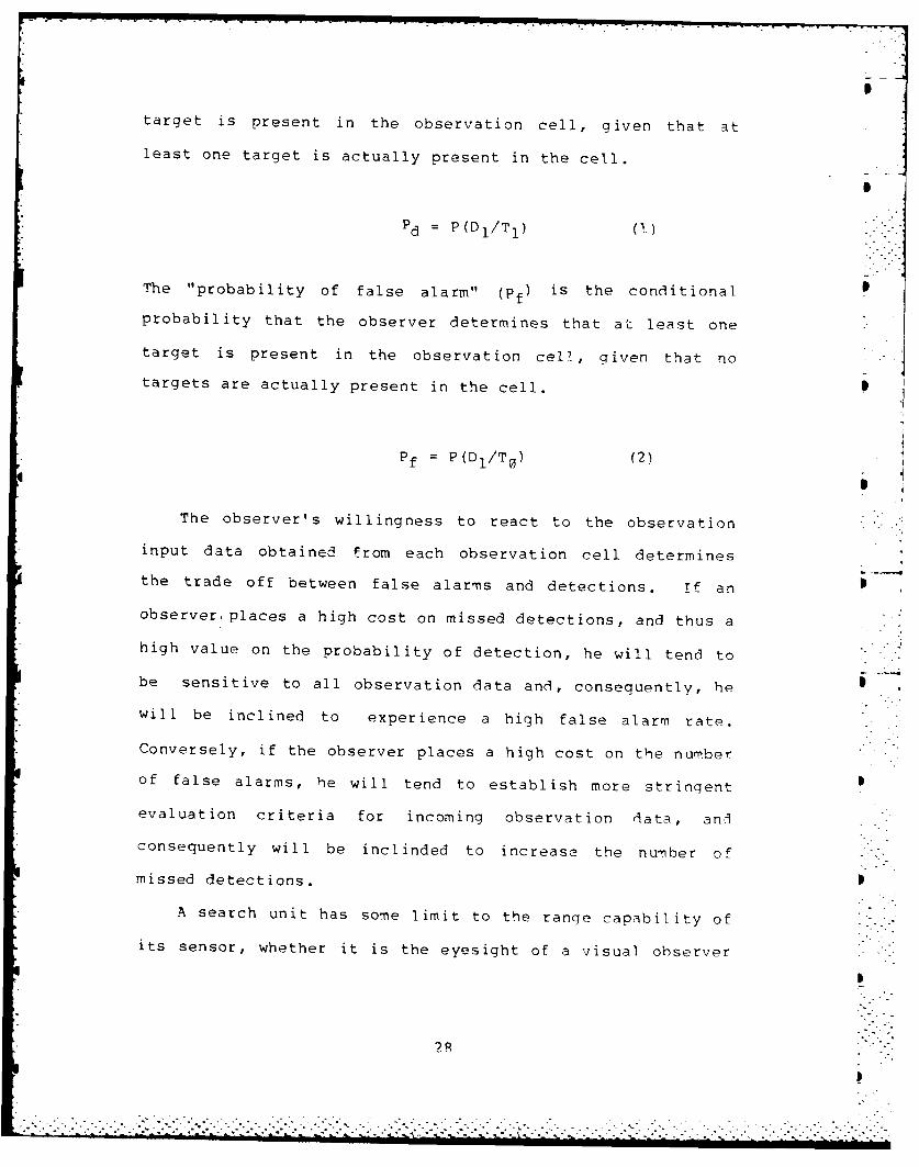
The "probabil ity of detection" (Pd is the ronditinnal
probability that the observer determines that at least one
27
"..
171
target is present in the observation cell, given that at
least one target is actually present in the cell.
S
Pd = P(D 1 /T 1 ) (1)
The "probability of false alarm" (pf) is the conditional
probability that the observer determines that at least one
target is present in the observation cell, given that no
targets are actually present in the cell.
Pf P(DI/TO) (2)fS
The observer's willingness to react to the observation
input data obtained from each observation cell determines
the trade off between false alarms and detections. if an
observer, places a high cost on missed detections, and thus a
high value on the probability of detection, he will tend to
be sensitive to all observation data and, consequently, he
will be inclined to experience a high false alarm rate.
Conversely, if the observer places a high cost on the number
of false alarms, he will tend to establish more stringent
evaluation criteria for incoming observation data, and
consequently will be inclinded to increase the number of -
missed detections.
A search unit has some limit to the range capability of
its sensor, whether it is the eyesight of a visual ohserver
I~k. . .. .... .. ... . b . , . , - . ..- : .- { - : . - <.- -. " ---:--: i--; ;..- , .- _.._.' -.;',. -"....- i, -" i,' ..

or the maximum range of i radar. This distance is known as
the "maximum detection range" (see Figure 3) . Since an
aircraft can sweep its radar back and forth to search both
sides of an aircraft's flight path, or a visual observer can
be posted to search each side, the maximum detection range
is doubled to equal the "maximum detection distance" (see
Figure 3).
MAXIMUM --
DETECTIONRANGE MAXIMUM SWEEP
...... .. DETECTION ..... WIDTH .MAXIMUM DISTANCE
DETECTION - - JRANGE
F.gure 3. Pictorial Presentatio 0 of a Search Sweep
Clearly, any visual observer should understand that his
ability to easily see and identify a target is a function of
his distance from the tarqet in question. When an aircraft,
on a constant course, encounters a surface tarqet (shin,
raft, etc.) the very high speed of the aircraft, relative to
the surface target's speed, creates a straight line
encounter" [Ref 14]. For this kind of encounter the
relative motion of an aircraft 9nd a tarqet are best
depicted as in Figure 4, where the aircraft is at the origin
and the Y axis is aligned with the aircraft's fliqht path.
- t-
. .. , . . . ..- <
. . . . . . . . . . . . . . . . . . . ..,. . . . . . . . . ..,,nl mn¢ lun J j . . _ ,.,,.- -. -. - - - .. -

in the refpronc-2 fraime of fiqure 4, the tarclet woult' annear
to move paral lel to the Y axis at the aircraf t's sneeli in!
at some "lateral ranrme" X. r3teral rarn -e is the horizontal
range at the clos-st point of ar'proach (CPat). CPA is the
tarqet's horizontal1 ranie when the t-irqet intprsects t' - X
axis.
YA ,ITARGET
Fiquire 4. straiiqht TAine Fncounter
For a stra iriht Iline encounter the orohabhlilty of
3etection cain be expressel as a func-tion of th- IlAteral
ranq,: X. In symbols:
P= P(x)()
Fiqur e S de-picts a number of d if fetrent Ilateral r inoe ctirves
to d ?monstr -ite ho-w the C37pabi Ii ty o f ciif ferent systems -ind
molels viry.

The definite ranqe law (Fiqure 5a) defines a simple
yes/no sensor that is assumed to always detect its target
inside a given range, and never outside that maximum range.
"
Aq
'4,)° 4 R
I D
I I p!I I
-, I '
E
Figure 5. Sample Lateral Range Curves
The inverse cube law (Figure rb) serves as the basis forI
aircraft visual searches. Fiqures 5c and 5d represent
modifications to the drfinite range law and inverse cube
law, respectively, and Figure 5e is typical for a radar to
include a low range orobability of detection dip caused by
sea clutter.
.- m,--- . . . . . . . . . . . ...

The mathematical area under the lateral ranqe curve,
represents the effective search (sweep) width W. That is,
W = PWx dx (4)
Figure 6a represents a lateral range curve for an ideal case
in which tarqet lateral ranges are uniformly distributed
across the detection range. Tn this case, the area under
A
ARANT O SG\HT M
MAXIM4dM 06?! eTlaw OITAVOCI - Twice MAX 0--
TARGEIS NOr DE IECIED
Ito OUTSIDE SWEEP WIDTH4
Figure 6. Graphic Presentation of Sweep Width
the curve is proportional to the number of tarqe-ts detectedi
and the area above the curve is proportional to the number
32
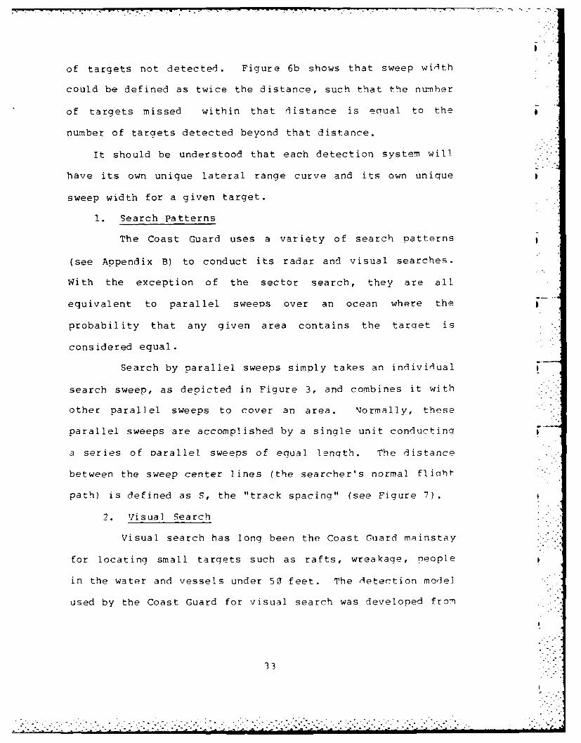
of targets not detected. Figure 6b shows that sweep width
could be defined as twice the distance, such that the number
of targets missed within that distance is equal to the
number of targets detected beyond that distance.
It should be understood that each detection system will
have its own unique lateral range curve and its own unique
sweep width for a given target.
1. Search Patterns
The Coast Guard uses a variety of search patterns
(see Appendix B) to conduct its radar and visual searches.
With the exception of the sector search, they are all
equivalent to parallel sweeps over an ocean where the
probability that any given area contains the tarqet is
considered equal.
Search by parallel sweeps simply takes an individual
search sweep, as depicted in Figure 3, and combines it with
other parallel sweeps to cover an area. Normally, these
parallel sweeps are accomplished by a single unit conductinq
a series of parallel sweeps of equal lenqth. The distance
between the sweep center lines (the searcher's normal flioht
path) is defined as S, the "track spacing" (see Figure 7).
2. Visual Search
Visual search has long been the Coast Guard mainstay
for locating small targets such as rafts, wreakage, people
in the water and vessels under 50 feet. The detection model
used by the Coast Guard for visual search was developed from
33
. . . °
N *......

the basic inverse cube law model, a simplifiod model of
visual detection. For a parallel sweep search, the model
I I w
......... ............................. .......
................. :--D-
Fiur .o Trc pcn n-oeaeFco
(C)Fgur 7TrcSpcnad.Coverage factor(sefqr7)idfnd y
C =-(5)
Using coverage factor, probability o f detection is
determined by using the qrao~hs in figure 9. Multiple curves
are provided to account for the probah i Ii tes created by
researching an area. A\ set of tables (figure P), based on

-,|,-,
J -- - -- --. -l I-
-"
• -, : I ! - "
C::
,-I[-1T -IT '[ i-::;
' • * '~ -'[ :i~::
>1 -~~i
3 -
.'-~
i i~ -
- . .
- - ;U ! J~ --
"
.. - : - , : :ii; -, :.
.
I
..-....
. II

experimental data gained through field testino, have been
developed to easily determine sweep width. The tables are
based on the following operational factors: Aircraft
altitude, target size, meterological conditions and sea
conditions.
U FOLOs SE
THOR7 0
40
20
as o 02 41 04 a0 07 as at to if 12 1 14 Is t 1 I s to I 20
COVIRAGI FACTOR
Figure 9. Probability of Detection
3. Radar Search
The principle of radar is to transm it an
electromagnetic signal and then detect any siinal reflected
back off a target. If a target is not present in an
observation cell, the input to a radar corresponding to the
observation cell equals only noise (non-target reflecte,! or
generated signal). If a target is present, the input equals
noise plus signal. The reflected signal received and the
random "noise" are convetted into a voltaae that produces a
"blip" on a cathode ray tube (scope) if the volt:iqe excee1s
an established threshold.
. . . .

A practical example of binary detection theory is
seen in Figure 10. There, the relative frequency
distributions are given for both noise voltage (no target
present) and noise plus signal voltage (target present).
Using a voltage threshold of Vt , a region of false alarms is
created at the upper end of the noise distribution where
observations exceed Vt • Likewise, an area of missed
detections is created at the lower end of the noise plus
signal distribution for observations less than Vt .
volts -
Figure 10. Decision Voltage Distributions
Althouqh different forward looking raThrs (FLAP) are
designed for such specialized purposes as weather aNoi(13ncR,
surface mapping and maritime search, all rad3r return
signals are subject to the same physicil real ities that
determine basic radar capability. The basic radar equation .-
serves to outline some important factors that eterrrine"
radar capability.
37
- .. . . . "" . . . . . . . . . . . . . . . -. .- . . . . . . . . . - . . - .. . . . , -. '. ,
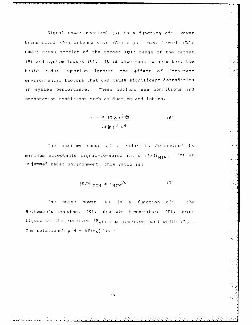
Signal Dower received (3) is a function of: Power
transmitted (?); antenna qain (G); signal wave length (M,) ;
radar cross section of the target (a) ; range of the tarqet
(R) and system losses (L) It is important to note that the
basic radar equation ignores the effect of important
environmental factors that can cause sianificant degradation
in system performance. These include sea conditions and
propagation conditions such as ducting and lobina.
S = P (G?)2 (6)
(4 i. ) 3 R 4
The maximum ranqe of a radar is determine& by
minimum acceptable signal-to-noise ratio (S/1)MTN . For an
unjammed radar environment, this ratio is:
(S/N)MTN = SMTN/N (7)
The noise Dower (N) is a function of: the
Boltzman's constant (K); absolute temoerature (T); noise
figure of the receiver (FN); and receiver band width (Pp).The relationship N = kT(FN) (BR)
• ., .

Using Equation 6, the simple radar equation, andl
Equation 7 qives"
R = P (G) 2 j 2
(4 3 (k) (T) (FM (BR) (SMIN) --
I
By using the signal power SMIN corresponding to the
voltage Vt, it would be possible to use Equation R to
determine the range corresponding to a qiven orobability of
detection and probability of false alarm. Such values
could, in turn, be used to estimate a lateral range curve by
using the technique described in Reference 15. However, a
more desireable way to determine a lateral range curve would
be by using operational data, rather than the method
outlined above [Ref 15J. .
To determine the overall probability of detection
for a radar parallel sweep search, given a lateral ranae
curve from which a sweep width can be determined, the random
search model described by Equation q can be useI.
-w/sP(S) = 1 - e (q)
The random search model yeil,s a more conservative, and some
argue, a more realistic result than does the model that is
based on precise naviiation and the inverse cube 'Law that
the Coast Guard uses. Fioure I 1 crinhically -ni-ts how

target to be detected (smoke, color, sianal mirror, flares,
etc.) can be assumed. The ELT mission does not require a
detection capability below 1(32 meters radar taroet cross
section.
For only the Coast Guard's "peacetime" missions of
SAR and ELT, would it appear possible that a 12 meter
detection capability could suffice, if performance and cost
tradeoffs were necessary. It should be remembered that the
Coast Guard approached the Navy concerninq an anti-submarine
quality FLAR, a point that might lend some focus to overall
Navy interest and funding priorities.
But in summary, to accomplish all search/oatrol
missions satisfactorily a requirement does exist for a FLAP
capable of detecting targets of 12 meter in radar cross
section. This finding is in agreement with the nevelooment
Plan for C-130 Aircraft Radar Retrofit fRef 221 written by
the Naval Air Development Center and Evaluation of U.q.
Coast Guard Forward-Looking Airborne Radars fRef 2 ] written
by the U.S. Coast Guard R & D Center.
B. PEPFORMANCE
Now that the driving mission requirement to satisfy all
search/patrol missions has been established at a 12 meter
detection capability, it is time to look at each soecific
radar system.
53
." -" " ",':"<'"--- - '-..'""."".'.-.""-"..-.-........................-.-.,.,..-.....-.....-,.-

Table 5. Summary of F_'q3 FLT Fstimate- )ar
Radar Cross Section Target Type Time qear-lieA
In Square Meters In Percent
VesselsI(-39 ft
50 Vessels 554n-lq ft
>13 Vessel sover Il1 ft
4. Military Operations Requirements
LRS protection of the sea lanes during a national
emergency would focus almost totally on an anti-sibbmarine S
role. Targets to be detected would include submarine
periscopes and snorkels of approximately 12 meter in siz-.
Visual target detection would be very difficult, since the
targets would be expected to do all possible to foil
detection efforts.
5. Mission Requirements Summary
Only the military mission definitely demands a
meter FLAR detection capability. While the SAR mission
would appear to benefit in 29.r-% of all time spent
searching, the targets in this cateqory would include rafts,
people in the water and small non-metallic boats that would
not provide the necessary 12 meter radar tarqet cross
section in all cases. For small SAR targets visual search
is still a viable alternative, since some effort by the
52
.I
.
• .-•. L . "- ."- - ..<''. ')"" " . . . . ) >"i•'. '.. .' ." -';< '.l .'- . * '•'='."':' L'-'''/id_'J

CuC
crU U )
- r 14 kc U, C l . ' r- C-4 .'4 mN co rN r- (N mN (
() C. t Na C -W - (' (Nr 1 4 l
Q) . c C4 a, *4 cc . s . 0 . .r .~ VI . 4 m U
= w ul ~ %D~ r- -- U r a L)m
(D Li
Li, -c cc-Ct ,r -c
a.0 C -zz...
t- UU, kz C. Ir4r n L -r r M
Q) 1-.0) .0~ 0Ji
M 41 (U'Lqw Q)E
Er-Li J>
>1 -qtn(Lq I A
o eu
(A. > 4 >1.
-4 CD

per aircraft. Clearly, all base line missions can be
accomplished by a minimum LRS fleet of 12 aircraft.
Although, as was discussed in Chapter 2, an actual minimum
LRS fleet size of 15 ooerational and 3 soare aircraft is
required to meet the "Bravo Zero" readiness requirement
levied on the five LRS air stations.
2. Search and Rescue Requirements
The Coast Guard Search and Rescue Assistance Report
(see Appendix E for a sample form and selected portions of
the report key) data base for FYR3 contains 405, off shore,
HC-130 sorties where the time spent searching exceeded on
tenth of an hour. In analyzing all FYP3 LRS SAR data, 42%
of total sortie time was spent searchinq.
Table 4 presents a summary of the FY83 LRS !AR data
broken down into a format based on radar target cross
section and sea state (see Appendix P for definitions of sea
state).
3. Enforcement of Laws and Treaties Requirements
Data available from the Pacific Area FY93 ELT data
base presented few details of interest concerning the FPT
mission. Of total time flown, roughly 81% was soent
searching or maintaining target surveillance. A t rqet
frequency distribution can only be estimated based on the
experience of this writer, and is presented in Table 5.
58-'
. ..... . . . . .
.- . . .". .
:" ": --.::<"'"? "",-," , " ":' " ' ": ' < - ,.-- : "':" :"'":" : .: .- :"' ."'" ." .,: " :. <,/:""-

I. Base Line Requirements
For the purpose of this thesis, base line HC-l3,w
requirements are considered to be the total number of
operational and spare LRS aircraft necessary to meet all
mission categories excluding SAR, ELT and Military
Operations. The reason for estimating this figure is to P
better establish the final impact that various FLAR systems
will have on LRS fleet size.
I
Table 3: Base Line LRS Requirements
FY87 FY88 FYR9 FY90 FYq I
Total 26,081 27,937 29,458 29,396 29,10?
SAR 6,459 6,451 6,305 6,(;q3 5,qRR
ELT 10,117 11,891 13,648 13,758 ] 3 ,7 q
..
MILOPS 6 6 6
Base Line 9,499 9,499 q,4q9 q,,549in Hours
Base Line 12 12 12 12 12in Aircraft
For the purpose of analysis, minimum LRS fleet size
was obtained by subtracting Appenl9ix A; SAP, ELT anti
Military Operations employment hours from Arpendix A; total
aircraft employment hour requirements for FY97-91. The
results are presented in Table 3. Further, Table 3 base
line aircraft estimates are based on 800 annual fliaht hours
49
<,--i ' - .-.i " " " ,'" " -i -' '" -" .i'1-< " . :-' -' -. ": .. ' :1 -.i< . .. -" i -': -.- 1.: -i i i..i- 2 1 -. i ....:- ... ' p

III. ANALYSIS
The purpose of this chapter is to reaccomplish the
analysis that established the need upon which the Coast
Guard based its decision to replace the APN-59B FLAR with
the APS-134 FLAR. Although Chapter Two provided the reader
with historical background data through the summer of IQP4,
the original Coast Guard FLAR analysis was completed in the
spring of 1982. For this reason, the analysis done in this
chapter will also work from the 19P2 time reference.
Therefore, all costs will be in FY82 dollars and the five
year operational planning period of FY87-91 will be usel.
In FY 82, it was believed that this time period represented
the first five year period in which a new APS-134 FLAR could
be fully operational fleet wide.
The analysis of need performed in this chapter will
address the three broad concerns of mission, nerformance,
and cost.
A. MISSION
Chapter Two identified the Search and Rescue,
Enforcement of Laws and Treaties, and Military Prenaredness
missions as the three mission categories that ootentially
will make the most extensive use of the HC-131 as a
search/patrol platform. This section will attempt to add
quantified dimensions to the requirements of each of these
similar but unique mission cateqories.
4q
........................... .......... ...... .... ........ ,--.

provide the FLAR Acquisition Program manager, who is in
engineering officer, with a final overview of the recyuire,9
FLAR capabilities desired, before contract negotiations were
entered into. The requirements were:
a. The radar must be able to detect a one
square meter target from no more than50 feet altitude in sea state five(Beaufort) at a minimum range of ten
miles (fifteen miles desired) with 7R%probability of detection.
b. The radar must be able to detect a li(square meter target from a minimumaltitude of 180 feet in sea state fivefrom a minimum range of 51 miles with78% probability of detection.
c. The radar must be capable of imagingweather and providing navigational
information to a range of 101 miles.d. The radar shall provide a minimum scan
of 180 degrees.e. The radar and associated equipment must be
capable of detecting and interrogating theIFF squawk of aircraft to a range of 110
miles.f. The radar display and controls must be
installed at the Navigator's positionwithout the need to remove any of theequipment currently installed.
g. The radar and associated equipment must becapable of providing latitude and longitudeposition information of selected tarqets.
h. It is desired that an additional radar beinstalled to provide weather detectioninformation to the pilot when the searchradar is operating in the search mode.
47
r -llll...................- i l ... ... . . . I .. ..

of how well the APS-134 performed in the maritime/zSW
environment of the BR-l15(4 aircraft. While findinqs of
these investigations provided some encouraging information
on the maintainability and reliability of the APS-134, it
did reinforce the EAE contention that the system would
require higher levels of maintenance than the Coast Guard
had ever experienced. It was decided that the radar's
exceptional ability to locate targets down to 12 meter
overshadowed the expense and difficulties that would be
experienced to achieve this performance.
The spring of 1984 marked the beqinning of the final
formalization of the APS-134 procurement decision as the
Navy entered the APS-134 FLAR into its FY86-87 POM cycles,
and the Coast Guard requested additional FY86 funds to
suppliment its existing FY82 FLAR monies. The procurement
schedule would be:
FY84 FY85 FYR6 FY-7
Systems 5 - 14 15
Support Equipment 1 - 3 3
Spares Sl.Pm - 4. (m S4.5m
The Coast Guard Chief, Office of Operations, in a letter
sent in July 1984 [Ref 211 , provided the Chief, Office of
Engineering with a listing of operational requirements for
the new LRS radar system. The purpose of this letter was to
46
• .. 4 :: -. '-: , ..................................."i...... .... -,...., l.. -. . . . . . . . . . . . . . . . . ..-....,

In October 1982, 23 AN/APN-215 color weather radars were
purchased as an interim HC-130 radar. The total APN-?15
acquisition cost about 82 million, and the radars would he
used to retrofit the MRR, H-3 helicopter, fleet once a
permanent LRS FLAR was obtained. During this time, flR-?,
the Aviation (operations) Branch, supported the Navy's APS-
134 proposal but EAE, the Aeronautical Engineering r)ivision,
was concerned over the complexity and suoportability of the
system.
In early 1983, some of the APN-215 radars that were
bought for the LRS had to be installed in the HU-2r, since
APS-127 deliveries were still behind schedule. At 'hat time
the first new HC-133 replacement aircraft were due for
delivery and Lockheed offered to supply AN/APS-133 weather
radars as replacement for the pirated APN-215s. This latest
development in the radar shell game called for, roughly,
half the LRS fleet to have temporary APS-133 radars and half
to have APN-215 radars. The HU-25 fleet would have both
APS-127 and APN-215 radars.
In late 19R3, the Coast Guard Research and Development
Center conducted field testing of the APS-127, APS-111 and
APN-219 radars [Ref 19], and compared them to tests of the
APS-134 conducted by the West German Navy [Ref 211.
In January 84, the OSR-2 HC-130 Program Facility Manager
and the EAE Avionics Program Manager visited Naval Air Winc-
Three of the West German Navy to obtain firsthand knowledge
.......................................................

to accomplish scan to scan integration, a key function
required to reduce sea clutter and increase resolution.
Hughes aircraft was the subcontractor for the DVST and
projected unspecified delivery delays on the bulk of the
procurement. The Coast Guard was forced to provide the few
APS-127 sets already on hand to the Falcon Jet Comoany to
avoid contract default and loss of the jets' warranty. As
each Falcon was delivered, its radar was removed and
resupplied to the Falcon Jet Company.
In July 81, The Coast Guard entered into negotiations
with the Navy for the purpose of obtaining a new HC-130 FLAR
replacement based on a NTNO agreement. The Navy saw value
in the retrofit of Coast Guard LRS assets with a PLAP
capable of detecting periscope and snorkel target of I
square meter radar cross section, based on the Coast Guard's
military mission. The Navy, through Naval Air Command and
with Coast Guard financing, tasked the Naval Air Development
Center (NADC) to determine which FLAR would satisfy their
mutual requirements and to write a development plan.
Appendix E is the executive summary of the Development Plan
for C-13(0 Aircraft Radar Retrofit, dated 12 April lq82, and
recommends the AN/APS-134 as the only suitable replacement
based on only the 12 meter detection capability. Tt iS
interesting to note that the executive summary does not
discuss the estimated 1982 life cycle cost of 890 million
that would be necessary to buy and support 34 radar systems ""-
for 25 aircraft.
44
... . . . . . . . . . , . • . . • . .. . . . • . . . . . . . . . . . • .

specifically for maritime search and surveillance.
Reliability of the APN-59B was never high, but due to its
age, mean time between failures (MTBF) had fallen to about I
50 hours.
Coast Guard budgets that included funding for a new FLAP
were submitted in FY79, 80 and 81, but it was not until FYP?
that $15.2 million was approved to acquire a new system.
Approval in FY82 was, in part, a result of the increase
national emphasis on illicit drug interdiction and the Vice
President's initiatives in the Southeast United States.
The FY82 monies were based on the 1979 plan to refit the
LRS fleet with the AN/APS-127 FLAR. The selection of the
APS-127 was to provide the Coast Guard with one FLAR for
both the LRS and the new MRS, the HU-25A Falcon jet, which
was to come into service during the early 1980s. The APS-
127 was developed for the HU-25A under a sole source
contract awarded to Texas Instruments, based on the roast
Guard's need for a maritime search radar of limited size and p
weight.
The Coast Guard felt the need for a new LRS radar was so
critical that a plan was considered in early 1.981 that would
divert APS-127 radar sets, already on order as clovernment
supplied equipment to the Falcon Jet Company for the HU-25A,
to temporary duty on Florida based HC-ls. Unfortunately,
by July 1981 it was clear that the APS-127 was in technical
trouble. The APS-127 uses a Direct View Storage Tube (VST)
43
p

small buys (1, 3, 5 and 4 plane purchases) every to
years to meet the need of a growing LRS work load. Tpy 107 q ,
it was clear that LRS basic annual utilization rates would
be exceeded by most of the five LRS air stations and that
the original 12 airframes would be worn out by the end of
that decade.
The LRS resource plan called for the renewal of the rRPS
fleet through the purchase of replacement HC-13q airframes.
The government would supply Lockheed Georgia with the
engines and high cost electronic equipment; these items were
to be removed from the retiring HC-130s. The expense of
this renewal of the LRS resource base made LRS fleet
expansion in the early 1980s out of the question.
Realizing the constraints on LRS fleet expansion an..
growing LRS mission tasking, Coast Guard aviation planners
looked at the HC-130s FLAR as a way to increase mission
efficiency and effectiveness. Since the rapidly growing ELT
mission used the radar as its primary search sensor, it was
natural to pursue this avenue.
The LRS fleet was equipped with the AN/APN-59B radar as
part of a "Navy type-Navy owned" (NTNO) agreement. Under
this agreement, the Navy had purchased the radars and naid
for all replacement parts. The APN-59B was originally
designed as a navigation/weather radar and wa- ui] t using
vacuum tube technology. Acccrdinqly, the APN-59 uses a
lower power and pulse ratio than does a FLAR desianed
42
. . . ...-

1. When minimum detection range is known:W = (1.7) (minimum detection range)
2. When average detection range is known:W = (1.5) (average detection range)
3. When maximum detection range is known:W = (1.1) (maximum detection range)
4. When no detection range is known:W = ((.5) (range to the horizon)
The few aircrews that attempt to compute FLAP
probability of detection usinq the SAR Manual guidance,
inevitably use the visual coverage factor/orobability of
detection conversion graph (Figure 9), as it is the only onp
provided. Since this graph is based on the inverse cube
law, a simplified theoretical visual search model, and
perfect navigation, the results could be erroneous.
E. LIFE CYCLE COST
The life cycle cost of a system is comorised of all
costs associated with a system over its entire life soan.
typical breakdown structure for a system will divide costsI
into the three major subcategories of: Research
development, test and evaluation costs; production costs;
and operations and maintainance support costs.
F. AN/APS-134 BUY DECISION
The LR9 fleet had grown from the original 1 2 Hr-130s
purchased in the early 1960s to a total inventory of 25 by
January 1978. The additional aircraft had been purchase in
41
I

probability of detection calculated for 3 parallel sweep
search varies between the inverse cube model and the random
search model.
OEFINITE RANGE LAW-r
P~ll INVERSE CUBE LAW
0
Figure 11. Probability of Detection for Parallel Sweep
The Coast Guard provides aircrews with no accurate
way to compute measures of radar search effectiveness.
There is no technical data readily available on FLAR systems
and no charts or nomographs have been produced for field
use. The only guidance provided is in the National Search
and Rescue Manual which states (Ref 17] that "Sweep width
tables for various electronic searches are not as readily
available as visual sweep width tables. Yet a sweep width
should be developed for all types of searches in order to
obtain the probability of detection and track spacin." To
determine the parameters for a radar search, it directs the
use of the "Electronic tocator Transmitter" sweep width
guidelines of (Ref 19]:
403.

The FLAR system comparison shown in Table is presented
in nautical miles of track spacing required to achieve a 78%
probability of detection for a parallel sweep search (Figure
3). For simplicity of computation and the purposes of this
thesis, FLAR sweep width was estimated as double the radar
detection range, based on an instantaneous single radar
sweep encounter, a 78% probability of detection and 11-r
probability of false alarm. Performance was computed for
targets of 12 meter, 102 meter, 502 meter and 1l(2 meter
radar cross section by using the range derivative of the
basic radar equation (Equation 8 and Swerling case 1 tarqet
model charts) . FLAR track spacing was calculated by using
the random search model (Equation 9) and solving for track
spacing, based on a 78% desired probability of detection and
the appropriate estimate of FLAR sweep width.
Table 6. Estimates of Track Spacing Based on 78% P
& Visual APN59 APS127 APNI13 APSI4 AP92,15
1 6.0 2.5 7.3 7.5 16.2 1.7..6* 3.5* 14.8*
10 q.2 4.4 13.0 13.3 28. 1.
50 10.1 6.7 19.3 1 q.9 43.3
10 0 13.2 7.9 23.1 23.6 51. 1 11.
*indicates preferred value based on operational testinq
54

The Coast Guard visual search model described in
Chapter Two was used to orovide a reference for comparison,
based on a 78% probability of detection for each listed
target size. Average, sea state one, search conditions of
1,000 ft. search altitude, 15 miles visibility, 20% cloud
cover and 10 knot winds were used to compute visual target
sweep widths and track spacing. The reader should recall
that the random search model for a parallel sweep search
used for FLAR computations, will yield a more conservative
estimate than will the inverse cube law model used for the
visual computations (see Figure 11).
Research published by the Naval Air Development Command
in Flight Test of the AN/APS-116 (XJ-2) Radar fRef 241, and
by the Naval Weapons Center in Airborne ASW Radar netection:
A Consideration of the Operator Factor for the AN/APq- P
Radar Under Low Sea State Conditions (Ref 251, indicate that
operator skill and alertness are especially critical durinq
small target encounters. During these encounters radar
scope target presentations can be faint, intermittant and
are easily masked or misclassified due to sea clutter. A s
shown in Table 6, data gathered during field testing of
selected FLAR systems by the U.S. Coast Guard and West
German Navy, reflect serious operational sweep width
degradation at the 12 meter target size for all but the APS-
134. Beyond sea state one, only the APS-114 shows a
detection capability aqainst 12 meter targets, with a sweep
5
. ."- -".... .. ... . . . . . . ................. .,,.h, ,',-.._ . .. i5l_.... .. .......a , - d ... '. .. . ..

width of roughly 20 miles in sea state three and 1 mile in
sea state five.
1. Performance Comparison
To compare the impact each system would have on
resource effort, it is necessary to first establish an
estimate for the number of square miles that would be
searched using the standard Coast Guard visual search model.
This was done by taking the estimated portion of each
search/patrol mission category dedicated to search
activities and adjusting it by the area that can be searched
per LRS hour. Or simply:
A = H V S (1()
Where area (A) is in square miles; hours (H) is the total
annual time spent searching; aircraft speed (V) is assumed
to be 200 knots; and track space (S) is the visual track
spacing required to achieve a 78% probability of detection
for a visual parallel sweep search.
HFLAR A/VS (11)
This total annual search effort (A), now represented
in square miles, can be adjusted back into flight hours
(HFLAR) by using the track spacing for each FLAR system and
the random search model. This is done using Equation 11,
56
.. ....

Ib
where area (A) is divided by the FLAP track spacing (q) that
is required to achieve a 78% probability of detection for a
FLAR parallel sweep search, with an aircraft speed (V),
which equals 200 knots.
Table 7 compares FLAR technology in the SAR mission
category for the years of FY87-91. It recognizes that 42%
of total SAR hours are spent searching and that the SAR
employment Hours presented in Appendix A are based on visual
search capability.
Table 8 compares FLAR technology in the ELT mission
category for the years FY87-91. It recognizes that 91% of
total ELT hours are spent searching and that the EL'
employment hours presented in Appendix A are based on APS-
134 search capability. Further, it assumes that a visual
search would take at least 50 percent longer than an APS-134
search for medium and large targets [Ref 261.
Since Coast Guard military search/patrol sorties are.
only conducted during times of national emergency, no sortie
time has been programmed into the oeacetime orojections
presented in Appendix A. But, it is estimated that the APS-
134 would have at least a three fold track soacing arIvantaqe
over a visual search conducted in a sea state one
environment.
2. Performance Summary
Table Q summarizes the total impact that FLAP
technology is capable of generatinq in FY87-ql. Included in
.7

-4 r-ccr-~~ cc r 1 -L r -4 0,r r- C. 4 - Lr r- I: k f t-. r- k
z Z c a:o cr- ~;C 1-4 -4 %r tr UL ULr '(N(NNN allCCr- c
r- -K rr)C4- r .m Cj--s "r~. Cec N krc .c U Ur TLr -L4 C L
MF--Tc ufj m -4 r- -4 _4 c z' c
-4 -4 c' cl CNc. r.w-
>. a. .4 16-1(
.0
(U (N r) r- cc C14 %Nt. r- e- 4 M Lfl .-d CC Ln o LCn c- ' t- co r_- a% ff'
F n cc co cc ~ 'a oc r- MC;M M m m-4 r- -4 -1 C\JrnCN-4 4
0 1- -4C -4r CJr
c.0
Z U)f "C(' r M~ ( NJ C14 IJ( m -4 0 o'c kc-W(N -T ~ - m(N C,4 m -r en f ..C oco0 of r- N 4 -4 -4 U)u'Lr U-)Lrn U-) CN "NCN aO'0 r-'.o
O -- 4_ 4- (4 C14 " CNr.
* 0
r- CO N r- M- r- (N r- U) %D a% r- r-C3, -4 -TLn r- M c 1 %.0~.C r- 10
M0 CD 00C) o CN " -4 -4-4 Ln Ln Ln Ln L r4 N N 4 N a%01)cor- .0(U -. 4 -4 -4 -4-4 ,-4 C1 N"cNrtlJN
-4 in0-

-lq - r- r- %Z fs 0: m ' Ln Lr) rnc nC%
. -4 .- 4 .- 4 -.4 -4
UUEr-
m) C)alm aO -e r lL) U)f lLnL -L f ,O
4J4
m u a 4c- N% D ma M 44,. U')J~~( c4', ~ C -4m )
tr cq4. qwF l - q V t .,I-C O 4N C
0).
En mU) r r , L) 4 - c 0 r-4 qc OC OC0 N-4 'M N .;-4 0. -4 4 .- 4 (1 e N cc ~ all U
Ln C U WMM " nU) f Z
03
U) c r-T -Ln V4)u-r r- - q- S C4v f
-4 - r4 C1~4 4 % f-m 7N-i l -q'W t~r' ) C1 -k %a o w
.00
U 59

mr tr - cc NC m0 ' w% -C t fc f
(nl z -V L - c % 'r4 r- o 0 C. r M Cr- (13 C.l
cr - - CN ' 4 ( (N
-4 a Lfl Oc.m . m ~N a% Lfl V I-, ~ o C-r 4 -
Er c rMC4M ; . o 00 f --T-4 MC 4
-Ioc q T Ul r Ck -4 -4 M(aMc -4 -4 -4
(V m M0(VV0 - r '4r4C
r -4 m --I C'Oa, C(%4 -- 4( CN (N C(4N 4c 0
CL L 60u- Lr Ir 00 - -4 - -. %C r- r- r-0 -41..
r-4 wQ)
-CL
U)4 C-~ r-. -4 (N c ,T ar r- qt : is a, ts .- N C14 (N (Ndii
V- aC'a, r- CO%,- oR ,Mt C- O% N Qia. L CLflL L cc -
4 (4 N qT .r-r-
tr-4 m-44 U
CLI I- I4V M M ma, 1 4(N 0 -c C N k
E-i4-)VU
ootC r -T---- c (NC(-4MN(NND U>i pl rj
-4 4n -4(N(N(N( M W441
.4 ) 34 -4 Cl) -4 crC a
00 0 o 0 0 a
601.

this summary are: The total hours required by each system
to accomplish the search/patrol missions of SAR and FUL7;
total search/patrol hours required and the short fall of Plq
hour LRS aircraft required beyond the base line fleet of 12
aircraft.
The information presented in Table q serves to
reinforce the obvious differences between radar tynes. "he
APN-59 and APN-215 were designed as weather radars. Their
performance as a search radar is barely on a nr with th-
results that could be obtained by condurtini -i - -i
search, given an average day. The APS-12-7 anl - r
roughly equivalent in search performance, with t h Q C*-1.4
superior to all.
Production effectiveness factors (7
calculated by dividing the totil n umber if Visu.....
search/patrol hours required, by the total number of FLAP -
search/patrol hours required. Table 10 presents thn
production effectiveness factors for the hinhest fliqht hour
requirements year of FY90.
Table 10. FLAR Production Effectiveness Factors
Visual APN59 APS127 APSI33 APS14 APN2?15
Hours 19453 19453 11732 11454 r126 lqA51
Factor 1.091 l.( 1.47 I.5(0 ?.35 l. (n
I.................................................................. ... x
C. COST
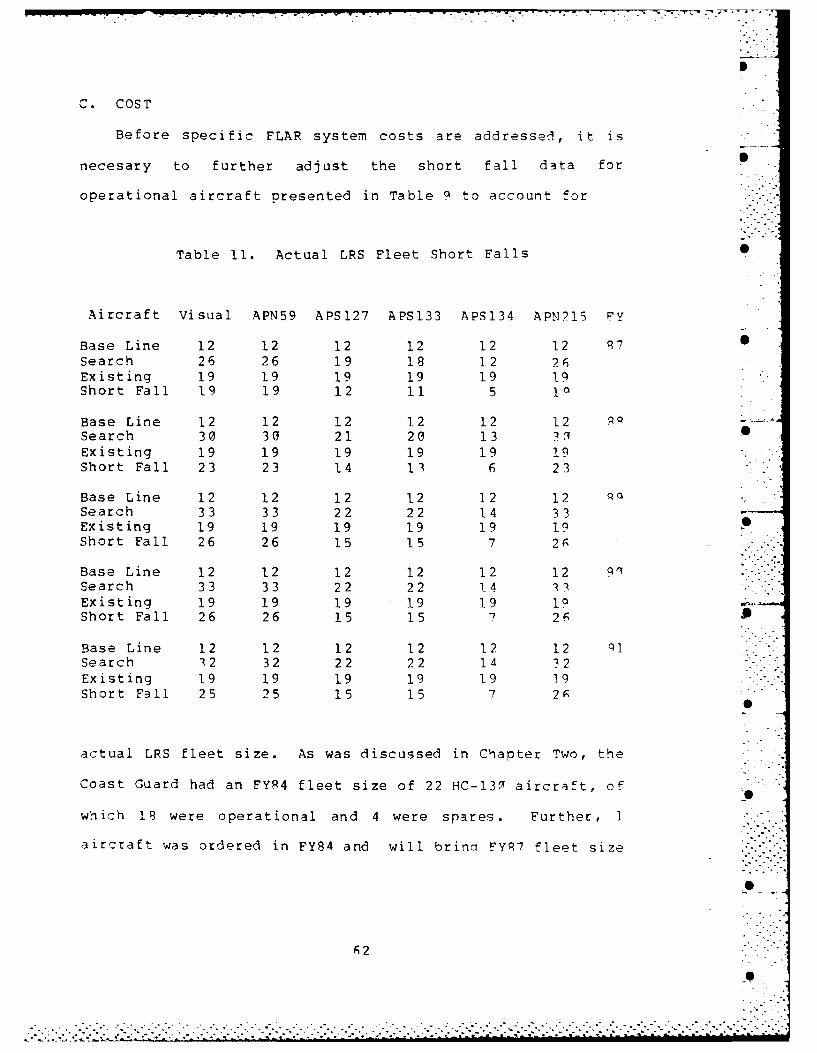
Before specific FLAR system costs are addressed, it is
necesary to further adjust the short fall data for
operational aircraft presented in Table 9 to account for
Table 11. Actual LRS Fleet Short Falls
Aircraft Visual APN59 APS127 APS133 APS134 APN?15 FY
Base Line 12 12 12 12 12 12 97 0
Search 26 26 19 18 12 26Existing 19 19 19 19 19 19Short Fall 19 19 12 11 5 In
Base Line 12 12 12 12 12 12 .Search 30 303 21 20 13 3,l 1Existing 19 19 19 19 19 19Short Fall 23 23 14 13 6 23
Base Line 12 12 12 12 12 12Search 33 33 22 22 14 33Existing 19 19 19 19 19 19Short Fall 26 26 15 15 7 26
Base Line 12 12 12 12 12 12 9.-Search 33 33 22 22 14 3Existing 19 19 19 19 19 InShort Fall 26 26 15 15 7 2r J
Base Line 12 12 12 12 12 12 Cl Search 342 32 22 22 14 32Existing 19 19 19 19 19 19Short Fall 25 25 15 15 7 2f
actual LRS fleet size. As was discussed in Chapter Two, the
Coast Guard had an FY84 fleet size of 22 HC-130 aircraft, of
which 18 were operational and 4 were spares. Further, 1
aircraft was ordered in FY84 and will brina FYR7 fleet size
. . .. . . . . . . . . .0; 2 [i i"
-.. .-- -,., .. .-. .. ... .-........ °.... .,... ...... .- ...... .. -......... .,-,.-.- . ,,°%:,- -,,," . " ....*,' - -- '-.l. =... . . . ..b ..... . . . . . . . . . . . . . . . .

I
to 23 aircraft, of which 19 will be operational and 4 will
be spare. Table 11 presents the LRS aircraft short fall
that results after adjusting for true LRS fleet size. Table 0
11 was calculated by adding the base line of 12 operational
aircraft, to the Table 9 required number of ooerational
aircraft for search patrol, and then subtracting the
existing FY87 operational aircraft inventory of 19.
1. FLAR Equipped LRS Costs
The detailed determination of costs in a purchase
as large and complex as this project, could serve as a
thesis by itself. For this reason heavy reliance has been
placed on existing, general cost data. Appendix G is a
summary of individual FLAR system costs taken primarily from
the Development Plan for C-130 Aircraft Radar Retrofit.
Appendix H is a summary of LRS acquisition and operational
costs provided by the Budget Division of Coast Guard.
Headquarters. All cost analysis will be analyzed in FYP2
dollars.
FLAR costs assume a worst case scenario that iqnores
the "Navy type- Navy owned" advantage being souqht for the
APS-134, where the acquisition, spare parts and periodic
depot maintenance costs would be borne by the Navy. Tiis
scenario recognizes the low project priority the Navy may
have conveyed when, after the Coast Guard approached the
Navy, the Navy asked the Coast Guard to fund the retrofit
. . . .° '.
• . -°
study. Further, it acknowledges the Coast Cuard's
willingness to go it alone, if necessary.
FLAR package costing includes: Acquisition and
installation of systems for all operational and spare
aircraft, to include 5 site spares and 1 training school
spare; the operational costs of a maintenance manoower
differential, maintenance consumables, comoonent rework and
spare parts; and the initial costs of qround supoort
equipment, publications, initial spares and transition
training.
LRS costing includes: Air station personnel; the
operational variable costs for fuel, aircraft maintenance
and depot maintenance; fleet overhead costs for traininq and
administration; and acquisition costs for any operational
aircraft and spares necessary beyond the existing FYP7 LRS
fleet size of 23 HC-30i aircraft.
Four additional assumptions have been male to
simplify the basic costing of the FLAR acquisition. One,
all FLAR and LRS research development test and evaluation
costs are considered sunk. Two, additional recruiting and
basic military training costs for any additional personnel
required have been ignored. Three, no consideration has
been made for additional retirement costs qeneratpd by
options that expand personnel strength. Pour, all
additional aircraft will be assigned to existina LRS air
stations without concern for air station physical capacity.
64
• 1
• . < -. .< _. .. < . .. ;--- . ..-. .-. '- ..-.-. -. ..-. .... . . . . . .."'. . . . . .-' "< -;.. i - .; -. - .; . . . . . .-
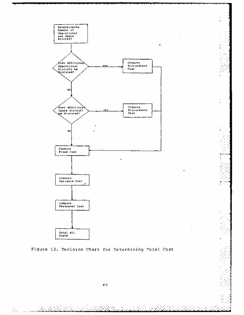
Oe termine theNumber ofOperationaland SpareAircraft
MutAdtoa Compute
Aircrad Costos
< utA-~toa Compute
Spar Arcraft y.- Prcrmn
ComputeFxd Cost
Cost
Figure 12. Decision Chart for Determining Total Cost

900
S 3
100I
APS-127
IcaI
0 10 -
Oprtoa LP Arcaf
Fiur 13 Toa Cos of Aicatb RSse
* I 66
-bedS9,.AP-33imiAN 1

Appendix I provides a table of estimated total costs
for operatinq LRS aircraft under various FLAR configurations
for the five year period of FY87-ql. Appendix I information
was computed using the decision process depicted in Ficure
12. Figure 13 provides a graphic summary of the estimated
system costs listed in Appendix I. From the Figure 1 3
depiction of total cost, it can be seen that all FLAP
systems examined in this thesis can be summarized into three
rough cost curves: The APS-134 curve; the APS-127 curve;
and the APN-59E, APS-133 and APN-215 curve.
D. COST EFFFCTIVENESS SUMMARY
The final stage of this analysis compares the cost and
performance of the AP(-134 FLAR against the other systems
examined. Figures 14 to 17 present the results.
Lev. ls of equal effectiveness (utility) are given by th.
expression:
U = (EAPSl34) (OAPsl34) +(F-System) ((System) (11)
Where (EAPS1 3 4 ) and (FSystem) are FLAR System effectiveness
factors and (QAPsI 3 4 ) and (n1ystem) are the number of
operational HC-130s equipped with each system.
For peacetime missions, where only a l(2 meter detection
capability is required, all FLARS are considered as perfect
substitutes. Thus, there is a constant rate of marginal
67.

xp PFNDTrX .)
FLAR TfN'I T" r''
T.cchnicrn nat, for the '/P-nF FT..-
ANSmITTER:
Frequency 9375 M*zPeak Power 70 KW
Pulse Width 0.35 ps; 4.5 us
PRF 1900 Hz; 180 Hz
.CEIVER:
Type LINEAR; STC - Adjustable Range/Depth to 40 nmi
Noise Figure 9.5 dB
IF Center Freq.IF Bandwidth 6.5 Mz; I Mz
NTENNA:
Gain 30.5 dB
SizeBeamwidth (AZ x EL) 3" x 5-
Peak SidelobePolarization Horizontal
Scan Rate 45 rpm; 15 rpm
ISPLAY: Storage type CRT; PPI format
EIGHT: 180 lbs.
RIME POWER: 115 VAC; 400 Hz 12A25 VDC; 6A
OLUME: 4.53 Cubic Feet
. . . . . . . . . . . . ..
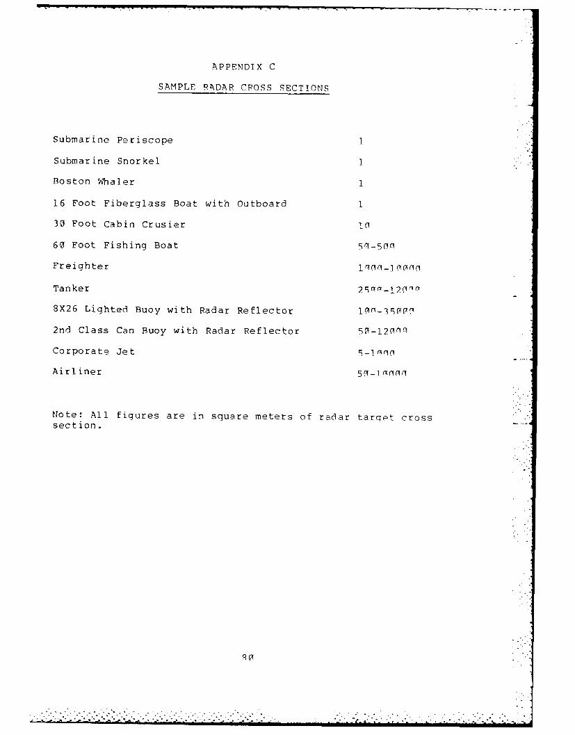
,. .-. . 1 ,**. * I I -a -. - el v-v -
APPENDIX C
SAMPLE RADAR CROSS SECTIONS
Submarine Periscope 1
Submarine Snorkel 1
Boston Whaler 1
16 Foot Fiberglass Boat with Outboard 1
30 Foot Cabin Crusier Ic
60 Foot Fishing Boat
Freighter 1 C-i .C
Tanker
8X26 Lighted Buoy with Radar Reflector
2nd Class Can Buoy with Radar Reflector 50-120nq
Corporate Jet 9_i •
Airliner
Note: All figures are in square meters of radar tarqet crosssection.
." . ."

APPENDIX B
SEARCH PATTEPN!
Parallel search
Sector Search
Expanding Square Search
Barrier Search
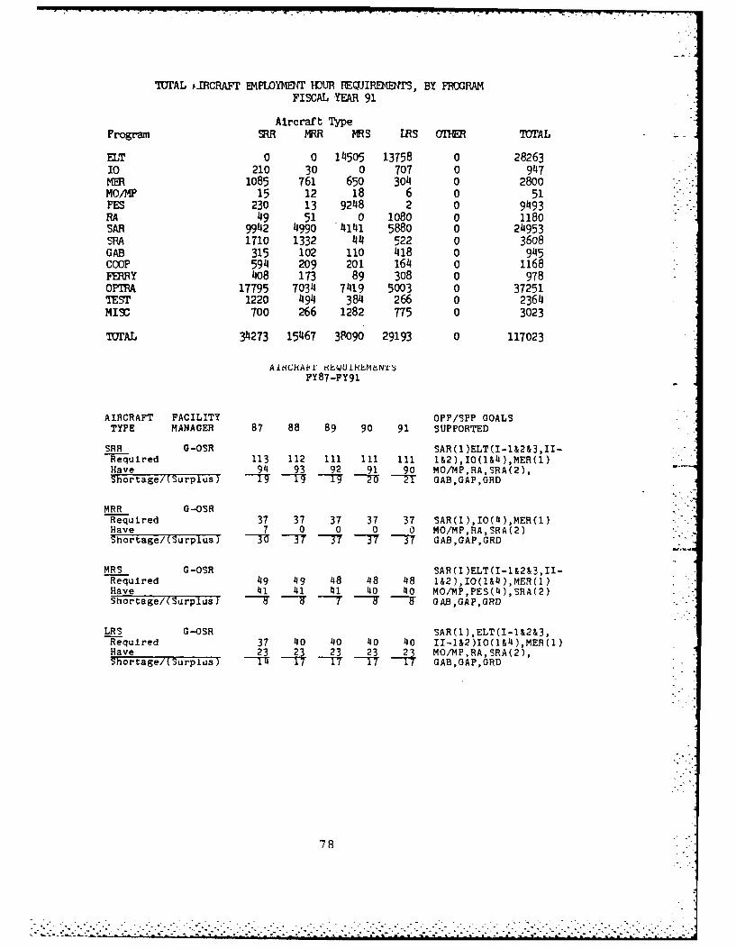
WFrAL #.IRCRAFT EMFLOEIJT IOUR FEJIREMBNTS, BY PROGRAMFISCAL YEAR 91
Aircraft TypeProgram MR MRR MRS IRS HE TTAL _-
ELT 0 0 14505 13758 0 2826310 210 30 0 707 0 947
1085 761 650 304 0 2800MO/MP 15 12 18 6 0 51FES 230 13 9248 2 0 9493RA 49 51 0 1080 0 1180SAR 9942 4990 4141 5880 0 24953SRA 1710 1332 44 522 0 3608GAB 315 102 110 418 0 945COOP 594 209 201 164 0 1168FERRY 408 173 89 308 0 978OPfA 17795 7034 7419 5003 0 37251TEST 1220 494 384 266 0 2364MISC 700 266 1282 775 0 3023
TWrAL 34273 15467 38090 29193 0 117023
A iNHAkl' h?,14U 1 H(t N'1' i
PY87-FY91
AIRCRAFT FACILITY OPP/SPP GOALSTYPE MANAGER 87 88 89 90 91 SUPPORTED
SRR G-OSR SAR(1)ELT(I-l&2&3,II-Required 113 112 111 Iil ill 1&2),IO(1&4 ),MER(1)Have 94 93 92 91 90 MO/MP,RA,SRA(2),Shortage/(Surplus) - -17 -- GAB,GAP,GRD
MRR G-OSRRequired 37 37 37 37 37 SAR(l),IO(*),MER(1)Have 7 0 0 0 0 MO/MP,RA,SRA(2)Shortage/(Surplus) "U -7 -77 -37 -7 GAB,GAP,GRD
MRS G-OSR SAR(1 )ELT(I-1&2&3,II-Required 49 49 4-8 48 48 l&2),IO(l&4 ),MER(1)Have 41 41 41 40 40 MO/MP,PES(4),SRA(2)Shortage/(Surplus) ---T -7 "T "--IT" GAB,GAP,GRD
LRS G-OSR SAR(1),ELT(I-1&2&3,Required 37 140 40 40 40 II-1&2)IO(1&4 ),MER(1)Have 23 2 23 23 23 MO/MP,RA,SRA(2),Shortage/(Surpius) --T'* -17 -T GAB,GAP,GRD
78
---------------- ... .... .... ..... .
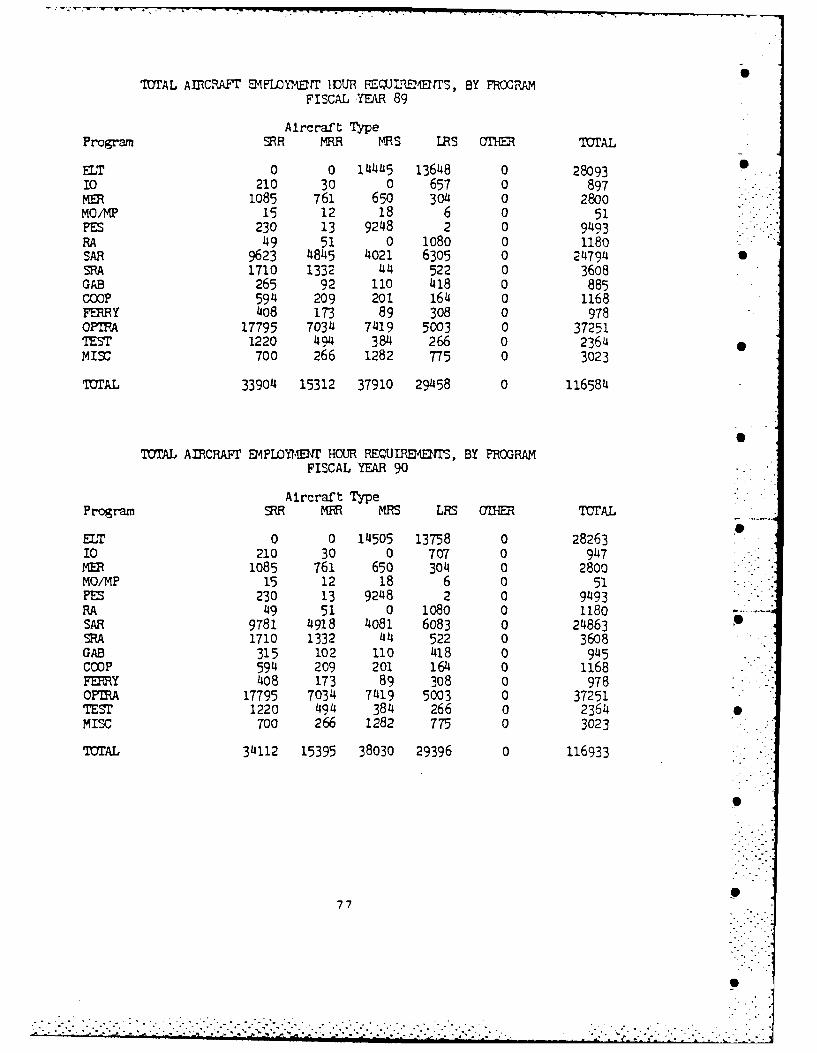
TOTAL AIRCRAFT EMFLOYM4UT IDUR JLWM fTS, BY FRCGRAMFISCAL YEAR 89
Aircraft TypeProgram ERR MRR MRS IRS aT=E TOTAL
ELT 0 0 14445 13648 0 28093 -10 210 30 0 657 0 897ME 1085 761 650 30o4 0 2800mo/MP 15 12 18 6 0 51
PS230 13 92148 2 0 91493R49 51 0 1080 0 1180SAR 9623 4845 4021 6305 0 214794SRA 1710 1332 44 522 0 36o8GAB 265 92 110 418 0 885COOP 5914 209 201 164 0 1168FERRY 4o8 173 89 308 0 978OPIFA 17795 7034 7419 5003 0 37251TEST 1220 494 384 266 0 2364MISC 700 266 1282 775 0 3023
TOTAL 33904 15312 37910 29458 0 116584
TOTAL AIRCRAFT EMPLOYMBI1 HOUR REQUIREENT'S, BY PROGRAMFISCAL YEAR 90
Aircraft TypeProgram MR MRR MRS LRS O=E TOTAL
SELT 0 0 14505 13758 0 2826310 210 30 0 707 0 9147
1085 761 650 3014 0 2800MOM 15 12 18 6 0 51PES 230 13 9248 2 0 9493RA 49 51 0 1080 0 1180SAR 9781 4918 4081 6083 0 24863SRA 1710 1332 44 522 0 3608GAB 315 102 110 418 0 945COOP 594 209 201 164 0 1168FERY 408 173 89 308 0 978OFIRA 17795 7034 7419 5003 0 37251TEST 1220 494 384 266 0 2364MISC 700 266 1282 775 0 3023
TOTAL 34112 15395 38030 29396 0 116933
77
., .. . .

APPENDY "
T072M1 rLRc r.lMPLC0VYMP11T 11n(IR PPOP F-"',Tr FY 0 -- n
IWJAL AIRCRAFT ENPLOYMJTl IDLWR REWIRE4EIMT, BY PROGRAMIFISCAL YEAR 87
Aircraft TypeProgram SRR MRR MRS IRS OTHER TTrAL
ELT 0 0 14415 10117 0 2453210 210 30 0 657 0 897
1085 761 650 304 0 2800MO/MP 15 12 18 6 0 51FES 230 13 9248 2 0 9493RA 49 51 0 1080 0 1180SAR 9314 4702 3909 6459 0 24384SRA 1710 1332 44 522 0 3608GAB 245 82 110 418 0 855COOP 594 209 201 164 0 1168FERY 408 173 89 308 0 978OPT A 17795 7034 7419 5003 0 37251TEST 1220 494 384 266 0 236MIX 700 266 1282 775 0 3023
TOTAL 33575 15159 37769 26081 0 112584
Note: Table does not include special aircraft requirements which are developedindependant ly.
TOTAL AIRCRAFT FIPDYOrr IDUR REQUIRE-OFrS, BY FIORAM"FISCAL YEAR 88
Aircraft TypeProgram SR MRR MRS RS OFlER IOAL
ELT 0 0 14445 11891 0 2633610 210 30 0 657 0 897MER 1085 761 650 304 0 2800MO/MP 15 12 18 6 0 51FES 230 13 9248 2 0 9493RA 49 51 0 1080 0 1180SAR 9467 4771 3965 6541 0 24743SPA 1710 1332 44 522 0 3608GAB 2'15 82 110 418 0 855COOP 594 209 201 164 0 1168FERRY 108 173 89 308 0 978OFTRA 17795 7034 7419 5003 0 37251TEST 1220 194 384 266 0 2364MITC 700 266 1282 775 0 3023
TOTAL 33728 15228 37854 27937 0 114747
7';"
:.':'........................................................................................

All LRS pilots and search planners must be provided with
the proper training and search planning materials necessary
to effectively utilize the capabilities of advanced Coast 0
Guard FLAR sensors. Reliance on the visual model and its
associated planning materials will no longer provide reliable
estimates upon which to plan searches or evaluate results.
Finally, the model used to calculate the probability of
dsetection for parallel sweep searches should be standardized
for both visual and FLAR searches. It is recommended that
the random search model be used. The recommended random
searchm model yields a 63% probability of detection for a
coverage factor of I and a 78% probability of detection at a
coverage factor of 1.5. By comparison the current Coast
Guard visual model yields a 78% probability of detection for
a coverage factor of 1 and a 90% probability of detection for
a coverage factor of 1.5. This readjustment downward of the
detection probabilities (see Figure 11) would more accurately
reflect operational performance realities.
75
-

IV. CONCLUSIONS AN) RECOMMFNDATInNS
The Coast Guard should continue actively pursinq the
acquisition of the APS-134 for retrofit into existing HC-l..
LRS aircraft. The APS-134 is the only FLAR analyze that
meets the search/patrol mission criteria of a detection
capability of 12 meter radar target cross section in
conditions up to sea state five. Further, of the systems
examined, it is the most cost effective solution to meet the
LRS search/patrol requirements projected through the end of
this decade.
Should the Coast Guard find it necessary to fund the APS-
134, instead of the Navy, one word of caution should be
added. if the newly approved LRS fleet (effective in FYRS,
the wording of the authorization is unclear) actually refers
to operational aircraft, instead of a total aircraft ceil ing,
the Coast Guard could field 27 operational plus 5 soare LP..
aircraft. Great care should be taken to fully analyze both
the primary performance need of search/patrol, as well as
other performance needs that might find a larger, mixed LRS
fleet more advantagous. Or, since no additional f und ini
accompanied the LRS fleet ceiling hike, it might be wise to
consider holding the LRS fleet at 26 operational and r soare
aircraft, the optimal to meet forecast search/patrol
requirements.
74

seen that roughly 33 operational, search/patrol, APT - 0E
equipped aircraft (45 total operational) would be necessary
to do the same job. Looking at the budget curves, it can be
seen that 26 operational APS-134 LRS aircraft would cost . ..-.
roughly $460 million to buy (assume original owneshin of 19
operational aircraft) and operate for the five year neriod,
versus roughly $900 million for the 45 operational APN-50F
equipped LRS aircraft capable of doing only the same
workload.
Should funding be available past that amount necessary
to field 26 operational APS-134 aircraft, it might not
always be rational to buy additional APS-134 equipped LRP
aircraft. Should $525 million be available, for example,
three APN-59E eqiupped aircraft could be purchased in the
place of two extra APS-134 equipped aircraft. This point is -
especially important if a secondary performance standard is
in effect, such as maximizing LRS fleet cargo hauling
capacity. In this hypothetical case, a mixed fleet of 29
operational aircraft would be best.
The basic assumptions used to simplify the cost analysis
would only lend more weight to the results presented. The
cost of expanding LRS air station facilites to accomodate 41;
operational LRS aircraft would be cost prohibitive by
itself. Likewise, if the Navy does finally orovide the APS-
134 as a "free good" through a Navy Tyne-Navy Owned
agreement, it would further restrict any other rational
substitute.
73

substitution resulting in iso-effectiveness lines that plot
as straight lines. The slope (M) of the iso-effectiveness
lines are calculated by:
E(APS134) (12)M =(12)-
E (System)
Since all the budget lines are concave and the iso-
effectiveness linci. are straight, a "qualified corner ooint"
solution exists. This means that based on the sinqle
performance factor of search capability, an all APS-13A LPS
fleet should be pursued; but, pursued only to the point
necessary to meet the minimum search/patrol requirements.
Should funding allow the purchase of aircraft in excess oF
those needed to meet search/patrol mission reauirements,
these additional aircraft do not have to be APS-13 4 equipped
to be of value. A mixed force might be more rational at
that point.
Specifically, for this analysis it has already been
established in Table 11 that 7 additional operational LPS
aircraft are necessary, based on specific search/patrol
flight hour requirements. Using Figure 14 as an example of
how each comparison graph is used, enter at the X intercept
of 14 operational, search/patrol, APS-134 equipped aircraft
(26 operational aircraft when the 12 base line aircraft are
added). Following up the iso-effectiveness line, it can be
72
.... .. ., .- :_ .- , ; .i, ['
.- -. . . . - ' - - '- ' - - . .. , ._ .. . - .' . . % . • . . . - . -
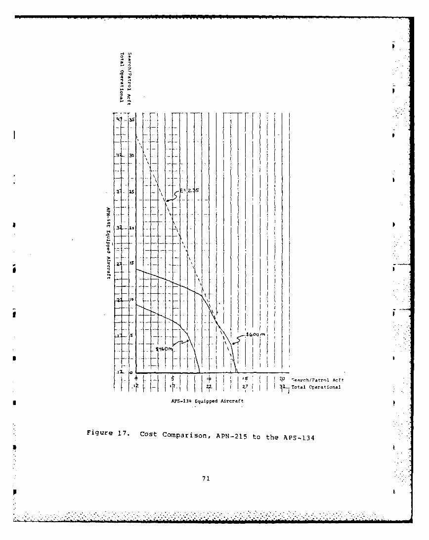
0
1. 0
'0
-0
mm
"1 ,4
n -I
, --
.4
54 - 3
S - ..
- - I ...
';..rc /Patro ... "
APS-134 Equipped Aircraft
Figure 17. Cost Comparison, APN-215 to the APS-134
71
"
-a
'-
I0 M od
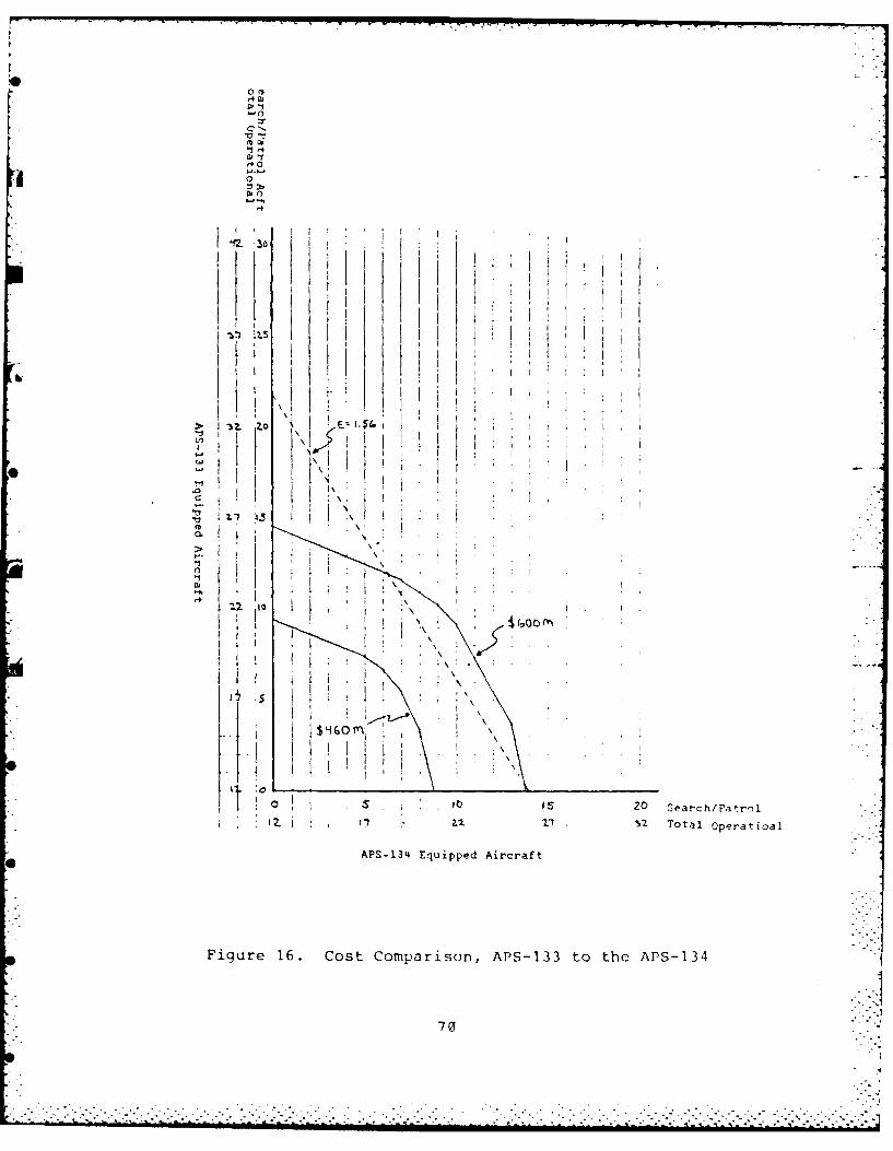
o
.1
*0
07
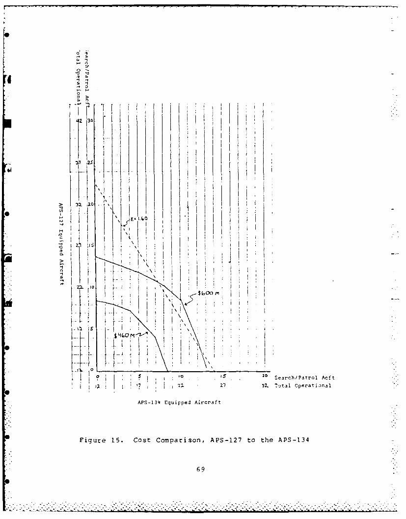
.. 0
*0a, 0
-to-
t-.. t-
0
I12 20 3Z TtlOprtoaAPS-14Eq ippdArrf
Figure 15. ~ CotCmaioAS17t h P 3
LA69
. .

I 2S
10
t *
20 erc/'to0Af
12- 17Z Z Ttl prtoa
AP-3 Eupe Arrf
Fiur 14 otCmaio ,AN5Et h P -3
'I8
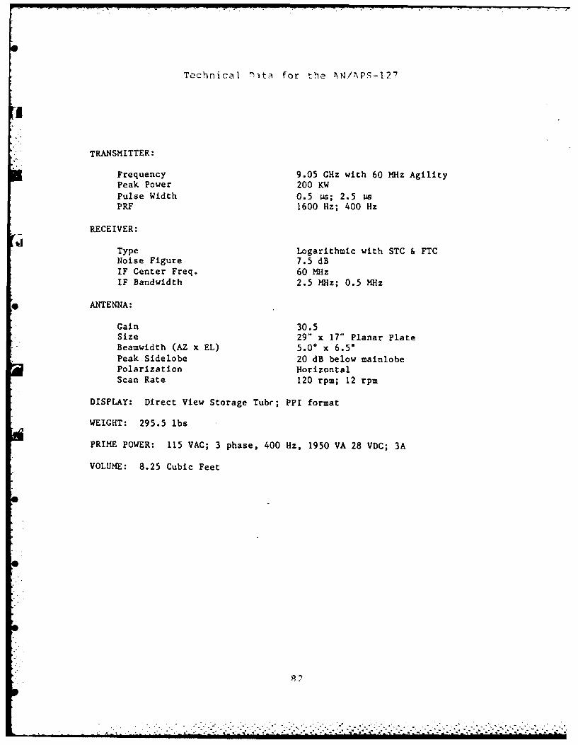
Technical 'Thta for the AN/\PS-127
TRANSMITTER:
Frequency 9.05 GHz with 60 MHz AgilityPeak Power 200 KWPulse Width 0.5 ps; 2.5 PsPRF 1600 Hz; 400 Hz
RECEIVER:
Type Logarithmic with STC & FTCNoise Figure 7.5 dB
IF Center Freq. 60 MHzIF Bandwidth 2.5 MHz; 0.5 MHz
ANTENNA:
Gain 30.5Size 29" x 17" Planar PlateBeamwidth (AZ x EL) 5.00 x 6.5*Peak Sidelobe 20 dB below mainlobePolarization HorizontalScan Rate 120 rpm; 12 rpm
DISPLAY: Direct View Storage Tube; PPI format
WEIGHT: 295.5 lbs
PRIME POWER: 115 VAC; 3 phase, 400 Hz, 1950 VA 28 VDC; 3A
VOLUME: 8.25 Cubic Feet
0
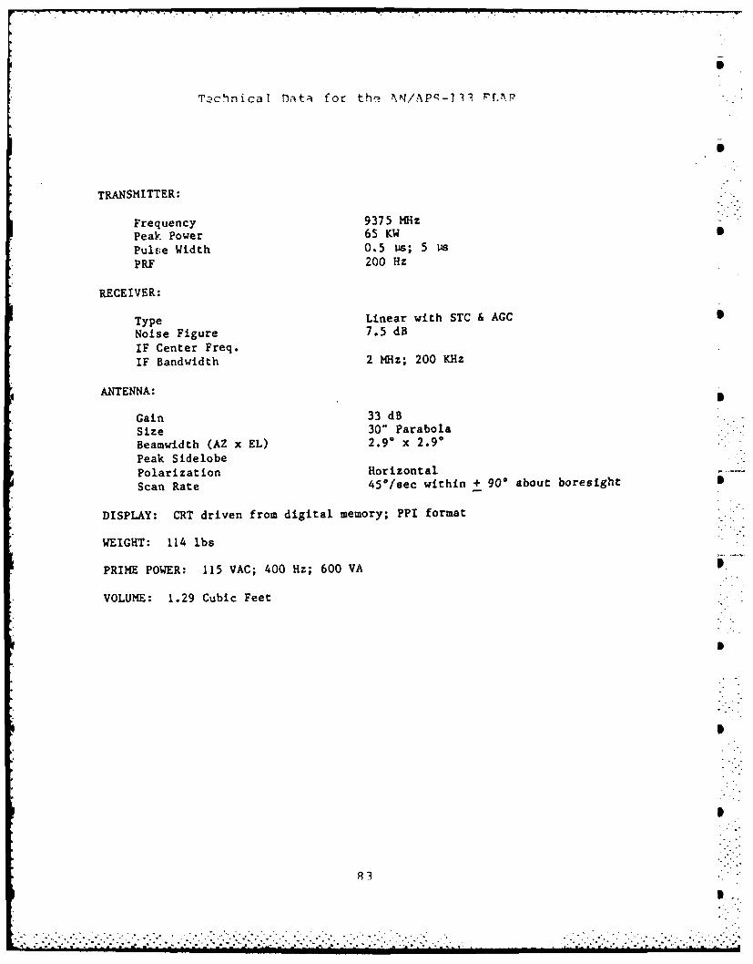
Tachn ica I Daita for th', ?\N/APq-1 11 PrA.
TRANSMITTER:
Frequency 9375 MHzPeak Power 65 KWPulse Width 0.5 vis; 5 lisPRs 200 Hz
RECEIVER:
Type Linear with STC & AGCNoise Figure 7.5 dB
IF Center Freq.IF Bandwidth 2 MHz; 200 KHz
ANTENNA:
Gain 33 dBSize 30" ParabolaBeamwidth (AZ x EL) 2.90 x 2.90Peak SidelobePolarization Horizontal
Scan Rate 45*/sec within + 900 about boresight
DISPLAY: CRT driven from digital memory; PPI format
WEIGHT: 114 lbs
PRIME POWER: 115 VAC; 400 Hz; 600 VA
VOLUME: 1.29 Cubic Feet
83

Technical Data for the 4x/Ap! -14 PfAr
TRANSMITTER,
Frequency 9.5 -10 GHzPeak Power 500 KWPulse Width 0. 5 Psp RF 2000 Hz; 500 Hz
RECEIVER:
hType Pulse Compression with AGC
Noise Figure 5.5 dBIF Center Freq. 1300 MHzIF Bandwidth 500 MHzPulse Compression Ratio 167:1Compressed Pulsewidth 3 ns
ANTENNA:
Gain 35 dBSize 42" x 26" ParabolaBeamwidth (AZ x EL) 2.4* x 4.0*Peak Sidelobe 20 dB below mainlobePolarization HorizontalScan Rate 150 rpm; 40 rpm
DISPLAY: MPD Driven by Scan Converter; PPI format
WEIGHT: 527 lbs
PRIME POWER: 115 VAC; 3 Phase, 400 Hz, 5.4 KVA
VOLUME: 8.87 Cubic Feet
............-..- ... ... .. ... ... .. ... ... ..
. . .. . . . . . . . . . . . . . . . . . . . . . . . . .
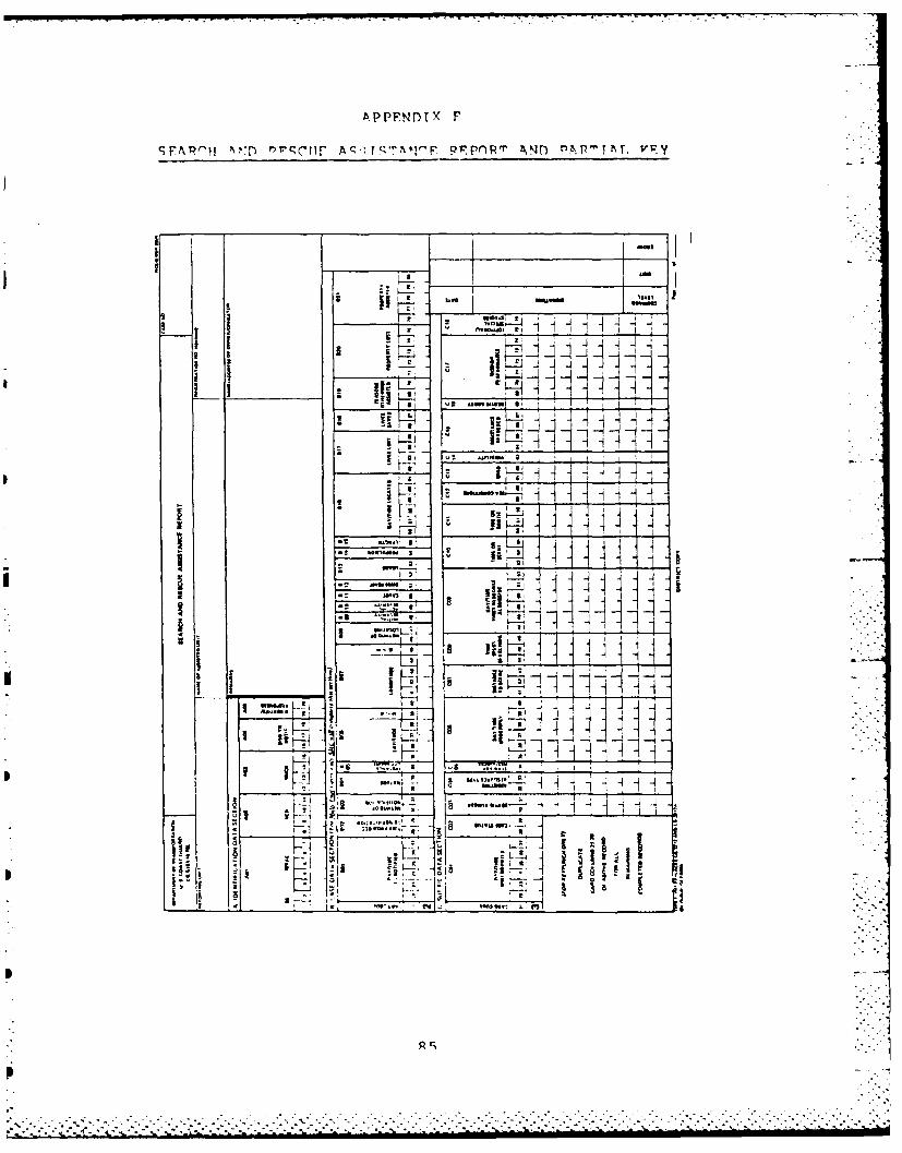
APPFNDIX F
1. FARI- : Aqc!C rF I ' 'Y'F .FPnR' r z , P T I\T, V Y
."
It
-2 , I -
I
. . .. .."
-- . ..... _. . ._. I~i ... ... '- ,: ,
* 4 I'i .
, . L..,...:::::
I ii ~. -. - -i.7"Ii
..: ~~ .. .. . . . . ... . . . .. .*:"

I*E U-E I U E l I I I , . _
A PARTIAL KEY FOR THE SAR ASSISTANCE REPORT
Block B04: Nature of the Incident
Vessel Land Vehicle01 Disabled/adrift 41 Collision
02 Aground 42 Disabled03 Capsized 47 Lost04 Fire/explosion 49 Other Condition05 Flooding/sinking06 Collision Land or Offshore Structure07 Lost/disoriented 51 Flooding08 Beset in ice 52 Fire/explosion09 Other condition 53 Other Condition
Aircraft Personnel
21 Ditch/forced landing 71 Personnel in water22 Crash 72 Man overboard23 Low on fuel 73 Swimmer in danger24 Bail out 74 Sickness/injury25 Fire/explosion 75 Diver in distress26 Mechanical casualty 77 Lost/stranded27 Lost/disoriented 78 Medivac29 Other condition 79 Other condition
Special Condition91 Overdue99 Case evaluated either as a false alarm or hoax
Block B05: Distance Offshore
0 Land 5 20 to 50 miles1 Inland waterways 6 50 to 1SO miles2 0 to 3 miles 7 100 to 150 miles3 3 to 10 miles 8 150 to 300 miles4 10 to 20 miles 9 Greater than 3q0 mil-+.
Block B15: Length of Assisted Vessel
0 Other tah vessel/ 4 40 to 65 feetfalse alarm 5 66 to 100 feet
1 less than 16 feet 6 Ill to 200 feet2 16 to 25 feet 7 201 to 300 feet3 26 to 39 feet 8 Greater than 300 feet
R6:ii
.........................-%.....-~,-... ...
. . . . . . . . . . . .. . . . . . . . . . . . . . . . . .

Block C07: Distance to Scene (Search Area)
The actual distance traveled from homeport, station,patrol area or diversion point to the nearest mile.
Block C08: Time Spent Searching
Actual time spent searching to the tenth of an hour.
Block Cli: Time on Sortie
Actual total time spent iunderway or airborne to thetenth of an hour.
Block C12: Sea Conditions
Greatest wave height to the nearest foot seen durinqthe sortie.
Block C13: Wind
Greatest wind speed encountered during the sortie inKnots.
Block C14: Visibility
Lowest visibility to the mile encountered during the
sortie.
87
........................ o.
. . . . . . . .. . . . . . . . . . . . . . . . . . . . . . . .°.. i..

A PPF Ir) TX Y
, (TATF q!1MN4M\ Y
SEA INDICATIONS WIND WAVES
SEA WAVE HEIGHT IN FEETVELOCITY
STATE RANGEDESCRIPTION DESCRIPTION (KNOTS) AVERAGE MAXIMUM
Sea may look like a min or or smallripples with appearance of scalaam Cair LCsa
0 but without oam crst. to 0-3 0 thanlight ain 6 inches
Wavelets that an short butpronounced. Crests may begin tobreak. Perhaps very few scattered Ughtwhitecaps. to 4.9 6 Inches I
gentle breeze
Large wavelets or small wavesbecoming larger. Fairly frequent Gentlewhitecaps, to
2 moderate 10.13 2 3breze
Small waves becoming larger.Frequent whitecaps.
Moderate$ breeze 14-16 3 S
Moderete waves, pronounced longfoam Many whitecaps. Chance ofsome spray. Fresh
4 breeze 17.19 4.5 7
Moderate to large waves form. Whitefoam crests are more extensiveevery where. Ivbobbility of some Fresh
S spray. to strong 20.24 8 12breeze
Large waves. Ses heaps up. Whitefoam from breaking waves begins tobe blown in streaks along the Strong
6 direction of the wind. May begin to breeze 25-28 11 18see spindrifts __.
Sea hesps up, Streaks long thedirection of wind. Moderately highwave% or greater length. Edges of Moderate
7 crest break into spindrift. The to 29-38 25 40foam is blown in well marked streaks fresh galealong wind direction.
High waves. Dense streaks of foamalong the direction of wind. Seabegins to roll. Visibility limited. Strong
8 Note: for cnnditions above these pie 3944 36 58limits, use Whole Gale, Storm, orHurricane definitlon.
.-%

APPENDIX G
SUMMARTZED COSTS,DEVELOPMENT PLAN FOR C-130 AIRCRAFT RADAR RETROFIT
FLAR FIXED COSTS -.
A. FLAR fixed costs assume an initial investment to
cover: publications,; ground support and test equipment;
initial spares; transition training; plus 6 FLAR systems, 5
for air station spares and 1 for the training school.
B. The cost by system:
1. APN-59E $1,335,0..
2. APS-127 $9,343,P0
3. APS-133 $I,312,000
4. APS-134 $28,90.,nO..
5. APN-215 $ I, 05o',QJ00 [-
FLAR PROCUREMENT COSTS
A. Procurement cost includes the cost per aircraft to
acquire and install the system on all operational and spare
LRS aircraft.
89.. . . . . . . . .. . . . . . . . . . . . . . . . . . . . . . . . . . .

B. The cost by system:
1. APN-59E 857,900~
2. APS-127 $412,500C
3. APS-133 0,90
4. APS-134 $1,206,300
5. APN-215 852,000
FLAR VARIABLE COSTS
A. Variable costs are for a five year peril and cover a
maintainance manpower differential, consumables, component
rework and rep1 enishable spares.
B. The cost by system:
1. APN-59E 2,0
2. APS-127 S9,342,~0
4. APS-134 $28,906,~00
5 . ... .. .. ... .. .. Sl q5 ,
7. 7 .;. . . . .. . . .

APPENDIX H
SUMMARIZED COST DATA; BUDGET DIVISION,
COAST GUARD HEADQUARTERS
LRS FIXED COSTS
A. Fixed costs cover five years of service wide support
costs to incude:
1. ATTC
2. AR&SC
3. SUPTCEN E-City
4. HQ-EAE
5. HQ-OSR2
6. Naval aviator training
7. Misc costs
B. S942,677 for 18 operational aircraft and adjusted by
1% for each additional operational aircraft.
LRS PROCUREMENT JOSTS
A. Procurement costs assume the cost of purchasing LRS
number 1791 reflects the FY82 market value of a fully
equipped LRS. Further, a 1:5 ratio of spares to operational
aircraft is assumed.
91
. . .

B. S14,500,(0 per aircraft
LRS VARIABLE COSTS
A. Variable costs are based on fuel, maintenance and
the aircraft program costs for a five year period.
B. $1746 per flight hour for S6,984,(xcW per R1111 hour
aircraft.
LRS PERSONNEL COSTS
A. Personnel costs assume a base line requirement for
15 (Bravo 0 requirement) operational aircraft operated from
five locations. Additional operational aircraft past 19
will add 18 enlisted and 3 officer. Personnel costs cover a
five year period.
B. $61,340,000 base line plus S2,255,PP per additional
operational aircraft.
92
-7.-...-....-.-...... ".'..->.... "...-...,2."•-",, .---.-... : ...-. ii
'
', k ~ ~~~.. . . . . . . . ..... : _" - '-,- - .._- . '-' -,_."_ ,, -'._. -"."- -, .'..,"" --,

APPENDIX I
C r r c C
.C w0- vr0z Ur c. laO~ 0~n~ vrnom0-w 1 MUto 4 -MUt
w 0 0 ;: CW w0 rur- 0WW U4)DMU w 00 ww - a)w-4 0q>r NO E- >~0f. Er .rn-r > C.Q-O E- bA 0-
"1 E0 CO 0 % 0 0 ft ~ ~ 0' .- 4 %0w0 1-m .0 m:. 0 %aZ om% 0~ m w m 0O . N% mi o mw 4 0%1 mm4 -' .4 -4 'o -cL 4= . 0
Inn: N~~.~ mI l :.-. I N 0 M4OU .%4 M 11 O0 in m fn
-4 -4 - ~ 4 N'
'. 0% m NI 4 O % , - C4 0% m o " Am O~ON W C40% r ufl C4 N mMC4 r.0, . q. C4 %V4 .- 4 4Il4 e N~ . Cf4 N'- 4 4 4 -W- 4 0%
N 0 0 -W M'4 M 0 m 0 S4 % mw %0 M0 4
-'.4 4 1 - -4
LnO O w4~s% mses' -w% 0r C 4N f O NC - b0SO M 4 ' L 40 M eC4 .4 M %C Mm N r. - (4O O tU C4I0 mt , e, M a 4 - 4 iC4 f-o~a N0 .s NI.w C4s~ IJ ,r4 %n N N N Ln -4NN %a. m5-q.' J4U- w U.44 OIJ-40 co.4r w W w.rh-u%4C % %
I . 4 -4 .4 .4 .4
W . MO 11C ~ (WIS~1 (I4*4 .4 C44514CWlp rn %D4 WOW m ' Wl n c
ul .e0 4 4 10 4 4 4 r4 4
u w L, f
93

*~a - C-l r ..
CU C W - C 0) - c a -C C C C'
-~~~ ~ ~ ~ ~ -0cw CCCc
-CQ m Q V) M Ca ) -um C C 0 a -M) M Q j -WL)M C E ,M r r
>- .r - .Q E- U.-o E- - - r EN - > N -. a. &->C .C E- -
m m N % -ON m m E nm . r-E %C EN -CE - Lr -r -
r- n m -- -L -- EN G ;: M mN -C Em - a L
z m Z EN m EN 7 EN -- ENE - E
~~~~C r4~~~Nr ~ ~ ~ ~ N~N ~ ~ ~ r ~ N~
r- a - omc c c - 7 cc C, - - EN mm N c% - cc EN - r EN cc- r
-1 -: - EN - EN - EN EN EN E Na r C cN EN EN EN EN EN ,cc,
N % M %C CN C Lr r4 r r4 C M Cl C4Lr P- ) r94 C
cr~~ ~ ~ is m cc .oMMI rrjmr mmwm M% m%

41 4 41 41 41
CC a)ca)CQ CW -C ) C CDaw c w 0) -w 0C 0
IC0 ' 0Z Cm - 0).:;flum 0) U' =)W 0 -)UL4 M)L U 0"0U M M-
u - - U - V) , um a- tn- a - U) U M (U U) U M 0 Enum Q tn L)
M a) -mo-0 a - ; - m w- - w 0U N NWv w NW
> *Q. cE - (L >Q Q >C - . - u>0-E- W~ - (L . N > N6 a. ~ > CL L
-z k M r a- tsN M -m t -w co m r4 Nc r4 N- NWf) N Nw r
- l) - - 1) - m - -w W w N -4 - N - -w N " W)
ND-o c - 1Wr N 0 N M ) W - L U N C*4 W U) Z f - -W -
o o ,m , c %Qm 7 mD oLc -a mw oLn(7 c Nc: w- 95ar
u ~~~ ~ ~ - -o ac - a McI m rr-Dm o M m r (nr 4%,- m mL. .m 7 %. r-
r- cc m rq cc cc en M r4 cn cc tn L.. . .. . .. . . . . . . . . . . . . . . . . . . .-a, ) 4 ( ( r r Nc.. . ..m
RD-R152 619 RN ANALYSIS OF THE ECONOMIC IMPACT OF THE AN/RPS-i34I FLAR (FORWARD LOOKIN..(U) NAVAL POSTORADUATE SCHOOL
USI FE MONTEREY CR R E DUNN DEC 84F/179 N
7 NLSIID / 79MENOMOEEE
1 0. _ 2-8 2E5
W Wliii'131 .
1-2I*

C -c c C C C
m 0 M1 - . 0 o :3 m 0 M 0 0 0 -0 m 0 I0 C t 0
-C0 LrC. = -11 4 1 .cc1 C4 w -w C4 , m cc . 1
(x , r- ~ 0 ', a,,. m 1 4m w.- to Im cc 4-n, ON %C r ' ,
N - - .d, ' W5 .-w , w .. " I -
. , 0 ,- m ', m -", L-n k 1 w cc
rq %D - .. . m c % w m 4 m a% w v4 -
N 330, -w ff. 0 n i k c -w tt .340 *- 10 03034 LnQ34 G . 0 m- 40
r4&. N eqt N3 U cN N %C (4%0 r4 N %v ('j .nW Nc4 - Nf4
0 a - -- G c M n m% Q% r t.mc NSfnq mr~" is03 ts N ~r- 'cOr m NG rL n -w
N4 NIA Q m e c4N.-%4m r)rUenr NN W 1.N~ (n-N% r.3C (N. m c fl w
a, %c. of ~ * %Dl ~ wCOu~ o ~r ~r- cj 0qwO
w a, im ccN3 ~0 N -w 47 o % %o-w a,~ a'NU hC4C L W (7 -DaW
.- N O ~ ~ S.. S W 5 4O~'~ .... u eS - ..
N -w m" " . .N ko cN40m ?..-4 V " 4 m - ar--N---" ,. , -r
a% - m4m c (" N q'Q im r-N m N N' LMM n On er- %D~ O m - r - N
r4N . r qL 4 r % m c c v 4% rq f W...U c4-N N.n~ N N e4%0 N.-.- N
in c L L m o r i M c r % Lnm ccc mLn w L coko m c 0m c N i ) 0w %om a 9
(. c - % I D - o eD tn c c Nm f4 com n = aat r m -96mlc
%Q %. - , wf- - m -w w a mW f a% -w a, D- w -r4 w v cm %

E--
V r C %P
IC r' I. 04W%Q 'V Im W - -I
N Nh f- M in
N -4 en N
%0 CD ON W
fICO CI N I
m m. f fn
If, NW r, C4 0% .5eq to r N00
-o S n %QN.1 mI 1
tD WC OD~$1
S ~ -' 97

LIST OF REFERENCES
I. Naval Air Development Center Report NADC-AE-60 10, Radar
Cross Sections of a Small Boat, by F. C. Prout, 2
December 1969.
2. Department of Transportation, Cast Guard Roles andMissions Study, March 1982.
3. U. S. Coast Guard, Aviation Requirements FY86-9(.September 1983.
4. U. S. Coast Guard, Search and Rescue Operating ProgramPlan FY 87-91, 5 July 1984.
5. U. S. Coast Guard, Enforcement of Laws and TreatiesOperating Program Plan FY87-91, 11 August 1984.
6. Operations Evaluation Group, Office of the Chief ofNaval Operations Report OEG-56, Search and Screening, byB. 0. Koopman, pp. 1-34, 1946.
7. Bloomfield, H. V. L., The Compact History of the UnitedStates Coast Guard, Hawthorne Books, p. 17, 1966.
8. Bloomfield, H. V. L., The Compact History of the Uniter-States Coast Guard, Hawthorne Books, p. 147, 1966.
9. U. S. Coast Guard, Aviation Requirements FY96-q(y, . 1-13, September 1983.
10. U. S. Coast Guard, Aviation Requirements FY96-9n, o. _-7, September 1983.
11. 0. S. Coast Guard, Aviation Requirements FYR6-oO, o. 1-7, September 1983.
12. U. S. Coast Guard, Enforcement of Laws and TreatiesOperating Program Plan FY87-91, pp. A-I-22 to A-I-23, InAugust 1984.
13. Naval Postgraduate School Report NPS55fO75(341 (Revised),Some Notes on Search, Detection and LocalizationModeling, by R. N. Forrest, pp. 1-3, November lR3.
14. Operations Evaluation Group, Office of the Chief ofNaval Operations Report OEG-56, Search and Screening, byB. 0. Koopman, pp. 22-24, 1946.
99
- 'i

- - r r' w r . ... ..
V-7
15. Operations Analysis Study Group, U. S. Naval Academy,Naval Operations Analysis, op. R5-93, Naval InstitutePress, 1977.
16. Naval Air Development Center Report NADC-AE-7022, Fliqht 0Test of the AN/APS-1l6 (XJ-2) Radar, by F. A. Mebus, 14July 1970.
17. U. S. Coast Guard, CG308, National Search and RescueManual, p. 8-71, 1977.
18. U. S. Coast Guard, CG308, National Search and RescueManual, pp. 8-71 to 8-72, 1977.
19. Naval Air Development Center Report NADC-AE-691l, RadarCross Sections of a Small Boat, by F. C. Prout, 22 -
December 1969. 0
20. Dornier Report KWS-F08-070-RA, KampfwertsteigerungBreguet 1150 Atlantic, L. Chabot, 19R1, VS-E'D (ForOfficial Use Only)
21. Coast Guard Chief, Office of Operations Letter MCC .0Serial 13290/1312q to Coast Guard Chief, Office ofEngineering, Subject: AN/APS-134 Radar, 17 July 19R4.
22. Naval Air Development Center Report NADC-AE-6qla, Raear . . -
Cross Sections of a Small Boat, by F. C. Prout, p. 1-1,22 December 1969.
23. Coast Guard Research and Development Center Peport C.G.-D-17-84, Evaluation of U. S. Coast Guard Forward-Looking Airborne Radar, by H. G. Ketchen and J. qt.Martin, pp. x-xi, March 19R4. -. --
24. Naval Air Development Center Report NADC-AE-7022, FlightTest of the AN/APS-116 (XJ-2) Radar, by E. A. Mebus, 1AJuly 1970.
25. Naval Weapons Center Report NWC-TP-4553, Airborne ASWRadar Detection: A Consideration of the Operator Factor_for the AN/APS-88 Radar Under Low Sea State Conditions,by D. G. Kinney, 1 November 1968.
26. U. S. Coast Guard, Enforcement of Laws and TreatiesOperating Program Plan FY87-91, pp. A-II-F-3 to A-IT-F-4, 10 August 1984.
99
........................................................
9.. 9 . .;]..'

BIBLIOGRAPHY
Acker, A. E., How to Speak Radar, Varian and Associate,October 1966 Revised January 1974.
Applied Physics Laboratory, Johns Hopkins University,Publication NWA-83-004, Threat Analysis Course, Producedunder Navy Contract N00024-936-5301, op. 39-49, January1983.
Barton, D. K., Radar System Analysis, Prentis-Hall, 1q6. A.
Department of Transportation, Coast Guard Roles and MissionsReport, March 1982.tudy, March 1982.
Hitch, C. J., Decision-Making for Defense, University ofCalifornia Press, 1965.
Hitch, C. J. and McKean, R. N., The Economics of nefense inthe Nuclear Age, Harvard University Press, 1963.
Joiner, B. L. and Ryan, B. F., Minitab Student Handbook,Duxbury Press, 1976.
Mayer, H. A. and Meyer, D. P., Radar Target Detection,Academic Press, 1973.
Naval Air Development Center Report NADC-77283-2t, AN/APS-127 Airborne Radar System Evaluation, by 0. Kessler and S.R. Swyers, 30 September 1977.
Rand Report P-4587, N Model for Evaluating VSTOL Versus CTOLCombat Aircraft Systems, by S. Horowitz and P. Shishko,March 1971.
Rao, V. V. L., The Decibel Notation, Chemical Publishing,1946.
Seiler, K., Introduction to Systems Cost-Effectiveness,0 Wiley-Interscience, 1969.
Sherar, R. C. and Rosenthal, J., "Don't Fall Into the RadarHole", U. S. Naval Institute Proceedings, oo. 5December 1973.
Smith, J. M., "AN-APS-134 (V) Maritime Surveillance Radar",IEE Conference Publication Number 216, pp. 39-40, 18 October1982.
100 .-'
I
. .. . . . ...*. .. . . . , . . . - . .*. . . . %. . . -. - . . .. ° ,•,

U3. S. Coast Guard, Aviation Requirements FY87-91 (DraftCopy) , September 1984.
U. S. Coast Guard, Commandant Instruction M16(0l8.1A,Planning and Programming Manual, 2 December 1983.
U. S. Coast Guard, Commandant Instruction 1123.-G, Abstractof Operations; Instructions for, 24 August 1982.

INITIAL DISTRIBUTION LIST
Mo. Copies
1. Defense Technical Information Center 2Cameron StationAlexandria, Virginia 22314
2. Library, Code 0142 2Naval Postgraduate SchoolMonterey, California 93943
3. Commandant (G-PTE-l) 2U. S. Coast Guard2100 2nd Street S. W.Washington D. C. 20593
4. LT Robert E. Dunn 3c/o CDR Bill Jacobs6209 Sodley Church CourtFairfax Station, Virginia 22309
5. Dr. R. N. Forrest, Code 55Fo IOperations Research DepartmentNaval Postgraduate SchoolMonterey, California 39343
6. Dr. P. M. Carrick, Code 54Ca 1_Administrative Sciences DepartmentNaval Postgraduate SchoolMonterey, California 93943
102
-7a..

4.
*FILMED
5-85
DTIC,*~~~~~," Z **.* *~:.K-