module 5: vsmp water quantity requirements - virginia · pdf filemodule 5: vsmp water quantity...
TRANSCRIPT

Plan Review Course
Module 5 | Page 1
Module 5: VSMP Water Quantity Requirements
Module 5 Objectives
After completing this module, you should be able to:
Discuss the Virginia Regulations’ requirements for quantity control and summarize the
conceptual differences between the new criteria and the current (Part IIC) Minimum Standard
19 criteria.
Describe the runoff volume reduction credits built into the Virginia Runoff Reduction Method
and how they are applied to the quantity control requirements for Channel and Flood
Protection.
Explain the concept of the “Stormwater Conveyance System” as applied in the quantity control
requirements for Channel and Flood Protection.
Discuss the “Energy Balance” concept, equation, and application.
Recognize the Curve Number Adjustment as applied using the Virginia Runoff Reduction
Method.
Module 5 Content
5a. VSMP Water Quantity Requirements Overview
5b. Channel Protection Criteria and the Energy Balance Method
5c. Energy Balance Design Example
5d. Flood Protection
5e. Limits of Analysis

Plan Review Course
Module 5 | Page 2
5a. VSMP Water Quantity Requirements Overview
The Evolution of Minimum Standard 19 Channel Protection Criteria
Erosion and Sediment Control Regulations:
Minimum Standard (MS) 19 of the Virginia Erosion and Sediment Control (ESC) Regulations
(9VAC25-840-40.19) requires designers to evaluate the adequacy of the downstream manmade
and/or natural channels to safely convey the developed condition runoff. The criterion of the ESC
regulations requires the designer verify the adequacy of all channels and pipes in the following
manner:
1. Demonstrate that the total drainage area to the point of analysis within the channel is one
hundred times greater than the contributing drainage area of the project (in which case the
channel or pipe system is assumed to be adequate based on the correspondingly small
impact of the project’s runoff to the larger stream or channel system);
2. (a) Natural channels shall be analyzed by the use of a 2-year storm to verify that
stormwater will not overtop channel banks nor cause erosion of channel bed or banks.
(b) All man-made channels shall be analyzed by the use of a 10-year storm to verify that
stormwater will not overtop its banks and by the use of a 2-year storm to demonstrate that
stormwater will not cause erosion of channel bed or banks; and
(c) Pipes and storm sewer systems shall be analyzed by the use of a ten-year storm to verify
that stormwater will be contained within the pipe or system.
If the existing natural or manmade channels or pipes are not adequate, the applicant shall:
(1) Improve the channel to a condition that meets 2(b) above;
(2) Improve the pipe or pipe system so that the 10-year storm is contained within the system;
(3) Develop a site design that:
will not cause the pre-development peak runoff rate from a two-year storm to increase
when runoff outfalls into a natural channel; or
will not cause the pre-development peak runoff rate from a ten-year storm to increase when
runoff outfalls into a man-made channel; or

Plan Review Course
Module 5 | Page 3
(4) Provide a combination of channel improvement, stormwater detention or other measures
which is satisfactory to the VESCP authority to prevent downstream erosion.
The regulations go on to apply numerous provisions to further define the implementation of the
respective solution. These provisions do not necessarily address the complexity of the analysis
required to adequately describe a natural channel and the relative “equilibrium” achieved in
response to the existing watershed hydrology, and the potential change (increased erosion or other
response) to increases in runoff volume, duration, or peak rate of flow.
Virginia Stormwater Management Regulations (Part IIC):
Guidance on the analysis of channel or drainage system adequacy and compliance with the
accompanying criteria is provided in the Virginia ESC Handbook (1992), the Virginia Stormwater
Management (SWM) Handbook (1999), and/or local program guidance. The specific criteria related
to the interpretation of the “site design” or detention option of item (3) has changed for some local
jurisdictions based on the updates to the Virginia SWM Regulations in 1999 with language now
captured in 9VAC25-870-97 of Part IIC (Stream Channel Erosion):
The locality's VSMP authority may determine that some watersheds or receiving stream
systems require enhanced criteria in order to address the increased frequency of bankfull flow
conditions (top of bank) brought on by land-disturbing activities or where more stringent
requirements are necessary. Therefore, in lieu of the reduction of the two-year post-developed
peak rate of runoff, the land development project being considered shall provide 24-hour
extended detention of the runoff generated by the one-year, 24-hour duration storm.
Virginia Erosion and Sediment Control and Stormwater Management Law:
An additional provision was added to the ESC and SWM Laws to establish a “safe harbor” provision
for those projects discharging to an eroded channel that by definition could not be made adequate
without implementing offsite stream restoration and/or stabilization.
The requirement to implement downstream channel improvements or restoration is often
impracticable in urban areas where impacts to stream channels have been ongoing for decades and
the burden of repair or stabilization cannot be equitably assigned to any single new development.
The concept of implementing a “site design” (item (3) above) that will not cause the pre-development peak runoff rate from a two-year storm to increase is a foreshadowing of the goal of the Virginia Runoff Reduction Method (VRRM); however the common interpretation of that language has been (and still is) to implement a detention basin design that limits the peak rate of runoff from the 2-year storm to that of the pre-developed condition.

Plan Review Course
Module 5 | Page 4
Nor can any degree of site design or onsite detention strategies on the new development project
effectively improve or reduce the existing rate of erosion and impact. As such, this lack of an
adequate channel could be interpreted as disallowing any further development in the watershed
until significant stream restoration is accomplished.
While a watershed scale restoration project may be under consideration in a jurisdiction, the “safe
harbor” provision was intended to allow the new development to proceed with on-site
requirements that would minimize additional impacts to the channel to the maximum extent
practicable (within the construct of onsite detention). Thus, yet another option for compliance with
Part IIC (or Part IIB) is provided (§ 62.1‐44.15:28 A.10):
Any land disturbing activity that provides a stormwater management design in accordance with the
following shall satisfy the Virginia stormwater quantity requirements and shall be exempt from any
flow rate capacity and velocity requirements for natural or man‐made channels:
(i) 48 hour Extended Detention of the water quality volume (WQv);
(ii) 24 hour Extended Detention of the runoff resulting from the one year, 24‐hour storm; and
(iii) Proportional reduction of the allowable peak discharge resulting from the 1.5‐, 2-, and
10‐year, 24‐hour storms using forested condition Energy Balance.
Therefore, projects complying with Part IIC have multiple options as may be allowed (or required)
by local ordinances and include various definitions that may be different than those in the new
regulations, including Adequate Channel, WQv, etc.
New Virginia Stormwater Management Regulations (Part IIB):
The Channel Protection criterion of Part IIB of the new SWM Regulations (9VAC25-870-66 Water
Quantity) requires that:
Concentrated stormwater flow must be released into a Manmade, Restored, or Natural
Stormwater Conveyance System and must meet the criteria established for each to the
limits of analysis as described in the regulations.
There are similarities to the old criteria especially for the discharge to the Manmade Channel (Part
IIC) or the Manmade Receiving Channel (Part IIB) where both criteria include ensuring non-erosive
flow velocity for the peak runoff from the 2-year storm event.
There are also differences, the most significant being that the designer is no longer responsible for
documenting the adequacy of natural channels (or more accurately stated: Natural Stormwater
Plan Review Course
Module 5 | Page 5
Conveyance System). Rather, the criterion simply requires the application of the Energy Balance
Method as a design standard that must be implemented when discharging to a natural channel;
regardless of its condition (unless a local watershed plan has identified an alternative criterion).
Another difference is the separation of the Channel Protection and the Flooding criteria into
separate items under the same subsection: 9VAC25-870-66.B. Channel Protection and 9VAC25-
870-66.C. Flood Protection. The following two sections address these two regulatory items.

Plan Review Course
Module 5 | Page 6
5b. Channel Protection Criteria and the Energy Balance Method
The Channel Protection Criteria is broken into three types of receiving Stormwater Conveyance
Systems as follows:
Manmade Stormwater Conveyance System
A Manmade Stormwater Conveyance System is defined as a pipe, ditch, vegetated swale,
or other stormwater conveyance system constructed by man except for restored
stormwater conveyance systems.
The Channel Protection criteria for a manmade conveyance system (9VAC25-870-66.1):
The manmade stormwater conveyance system shall convey the postdevelopment peak flow rate
from the two-year 24-hour storm event without causing erosion of the system. Detention of
stormwater or downstream improvements may be incorporated into the approved land-disturbing
activity to meet this criterion, at the discretion of the VSMP authority; or
The peak discharge requirements for concentrated stormwater flow to natural stormwater
conveyance systems (Energy Balance) shall be met.
Non-erosive capacity for 2-year peak flow and 1% Rule analysis OR
Energy Balance (Natural Stormwater Conveyance)
Photo: Center for Watershed Protection Photo: Center for Watershed Protection

Plan Review Course
Module 5 | Page 7
Restored Stormwater Conveyance System
Restored stormwater conveyance system is defined as a conveyance system that has been
designed and constructed using natural channel design concepts. Restored stormwater
conveyance systems include the main channel and the flood-prone area adjacent to the
main channel.
The Channel Protection criteria for a restored conveyance system (9VAC25-870-66.2):
When stormwater from a development is discharged to a restored stormwater conveyance system
that has been restored using natural design concepts, following the land-disturbing activity, either
The development shall be consistent, in combination with other stormwater runoff, with the design
parameters of the restored stormwater conveyance system that is functioning in accordance with
the design objectives; or
The peak discharge requirements for concentrated stormwater flow to natural stormwater
conveyance systems in subdivision 3 of this subsection shall be met.
Development (density, scale, etc.) and peak flow consistent with design parameters of the restored system and 1% Rule analysis OR
Energy Balance Method (Natural Stormwater Conveyance)
Photo: Williamsburg Environmental Group Photo: City of Charlottesville

Plan Review Course
Module 5 | Page 8
Natural Stormwater Conveyance Systems
Natural stormwater conveyance system is defined as the main channel of a natural stream and the
flood-prone area adjacent to the main channel.
The Channel Protection criteria for a natural conveyance system (9VAC25-870-66.3):
When stormwater from a development is discharged to a natural stormwater conveyance system,
the maximum peak flow rate from the one-year 24-hour storm following the land-disturbing
activity shall be calculated either:
In accordance with the following methodology (Energy Balance):
Q1-yr-Developed ≤ I.F.*(Q1-yr-Pre-developed* RV1-yr-Pre-Developed)/RV1-yr-Developed
Under no condition shall:
Q1-yr-Developed > Q1-yr-Pre-Developed
Q1-yr-Developed < (Q1-yr-Forest * RV1-yr-Forest)/RV1-yr-Developed;
Restore using natural channel design OR
Energy Balance (1-year storm event) OR
Safe Harbor Provision (from SWM Law § 62.1-44.15:28.10)
Photo: Ellanor C. Lawrence Park Fairfax, County

Plan Review Course
Module 5 | Page 9
where
I.F. (Improvement Factor) = 0.8 for sites > 1 acre or 0.9 for sites ≤ 1 acre
Q1-yr-Developed = the allowable peak flow rate of runoff from the developed site
RV1-yr-Developed = the volume of runoff from the site in the developed condition
Q1-yr-Pre-Developed = the peak flow rate of runoff from the site in the pre-developed
condition
RV1-yr-Pre-Developed = the volume of runoff from the site in pre-developed condition
Q1-yr-Forest = the peak flow rate of runoff from the site in a forested condition
RV1-yr-Forest = the volume of runoff from the site in a forested condition
OR
In accordance with another methodology that is demonstrated by the VSMP authority to
achieve equivalent results and is approved by the board.
The Energy Balance Method
The Energy Balance Method is intended to achieve a balance between the “energy” exerted on the
stream by the pre- and post-developed peak discharge. The formula provided does not actually
represent stream energy, but rather a simplification of an effort to balance the hydrologic response
characteristics of a developing watershed: impervious cover, channelization, and other impacts
associated with the developed landscape result in an increase in the volume and peak rate of runoff.
The Energy Balance utilizes the inverse relationship between pre- and post-developed condition
runoff volume to reduce the allowable peak discharge:
As the post-developed volume increases:
the ratio of the Pre to Post volume decreases; and
the allowable 1-year discharge (Q1post) decreases; and
the storage volume required to meet the reduced Q1post increases

Plan Review Course
Module 5 | Page 10
Why Energy Balance?
The Energy Balance could have been given any number of different names, and the Energy Balance
is a good descriptor. The primary driver of the method comes from two places: First is the Fairfax
County “safe harbor” provision that includes the proportional reduction in the allowable peak
discharge from a range of design storms.
The second is the mandate from § 62.1‐44.15:28 of the Code to establish regulations that
encourage Low Impact Development (LID). The use of the post development runoff volume (Post
Vol1) in the peak discharge formula allows the designer to take credit for the various LID or
Environmental Site Design (ESD) strategies that ultimately decrease the post-developed condition
volume of runoff.
The designer may elect to reduce impervious cover which is a self-crediting strategy independent of
the VRRM: less impervious cover means a lower developed condition Runoff Curve Number (CN).
Additional strategies such as minimizing impacts to soils and existing mature vegetation,
preserving open space, and implementing non-structural stormwater BMPs are specifically credited
within the VRRM and result in less stormwater runoff.
In addition to reducing the post-developed condition volume of runoff (Post Vol1) in the energy
balance formula, the reduced curve number as a result of the reduction in impervious cover and the
VRRM Curve Number Adjustment result in a double credit as an incentive to implement ESD
strategies.
The Curve Number Adjustment is discussed later in this Module.
Revisiting the allowable peak discharge equation above:
and reversing the logic in terms of implementing ESD strategies:
As the post-developed volume decreases:
the ratio of the Pre to Post volume increases; and
the allowable 1-year discharge (Q1post) increases; and
the storage volume required to meet the reduced Q1post decreases

Plan Review Course
Module 5 | Page 11
These results provide an incentive for implementing ESD because:
The strategies can achieve water quality compliance without large land intensive
stormwater practices; and
The use of the VRRM and the Energy Balance Method can decrease (or in some cases even
eliminate) the storage volume required for meeting the channel protection criteria
What Is the Improvement Factor?
The Improvement Factor (IF) is a statutory hold over from § 62.1‐44.15:28 that require the
stormwater regulations to improve upon the contributing share of the existing predevelopment
runoff characteristics and site hydrology if stream channel erosion or localized flooding is an
existing predevelopment condition. The Channel Protection criterion for discharges to a Natural
Stormwater Conveyance System assumes that the natural channel is not adequate and therefore
requires that the Energy Balance Method be used to determine the allowable peak discharge (and
storage requirements). It is conceivable that the post developed volume could be reduced through
the use of runoff reduction and ESD strategies that the ratio of Pre Vol1 to Post Vol1 increases to 1,
making the IF the basis for “improving upon the existing condition” by a factor of 10% or 20%
(equivalent to IF of 0.9 or 0.8, respectively).
Energy Balance Terminology
Both the designer and plan reviewer should become familiar with the terminology of the Energy
Balance method as it is documented in the regulations, as well as how various hydrologic methods
use the same values with possibly different definitions.
For example, the most common symbol in stormwater management documentation is that of runoff
peak discharge, Q, measured in cubic feet per second. However, the NRCS Technical Release 55
(TR55), the foundational document for computing urban runoff using NRCS methods, designates
the same runoff peak discharge, measured in the same units of cubic feet per second, with a lower
case q. To keep things interesting, TR55 designates the depth of runoff measured in watershed
inches as upper case Q.
Another important value that can be the cause of possible confusion is the use of RV as the symbol
for Runoff Volume in the Energy Balance equation as published in the regulations and noted above.
(Notice that the rearranged Energy Balance equation version substitutes these values with Pre
Vol1.) The VRRM Compliance spreadsheet uses the term RV to refer to runoff depth in inches, which
can be used in the Energy Balance equation in place of the runoff volume.

Plan Review Course
Module 5 | Page 12
Table 5-1 provides a summary of the different terms used by the different published sources,
along with the corresponding units. There is no absolute right or wrong version of the units,
as long as they are used consistently within the design.
Table 5-1 Hydrology Terminology
Considering the nomenclature distinction provided in Table 5-1, the Energy Balance
Equation:
can be re-written as:

Plan Review Course
Module 5 | Page 13
5c. Energy Balance Design Example
The benefit of the Energy Balance is the credit provided for using ESD and RR practices to reduce
the runoff volume and achieve a CN Adjustment. In principle, when ESD and runoff reduction
practices are used to capture and retain or infiltrate runoff, downstream stormwater management
practices should not have to detain, retain or otherwise treat the volume that has been previously
removed. In other words, the volume of runoff reduction should be removed from the volume
computations for Energy Balance and Channel Protection compliance. The challenge lies in how to
accurately credit the annual volume reduction when performing single-event computations of peak
discharge and detention storage from larger storms.
The following Design Example illustrates the Energy Balance method starting with the Curve
Number adjustment.
Compliance Spreadsheet CN Adjustment
The CN Adjustment computations start with determining CN and computing the corresponding
runoff depth.
Revisiting the Example from Module 4:
Consider design option 1 – no RR Practices: CN = 83 and the corresponding 1-year runoff volume (or
depth measured as watershed inches, RV1) as shown.
Design Option 1: No RR Practices

Plan Review Course
Module 5 | Page 14
Review Question: Where does the depth of runoff (RV1) come from?
Calculate using TR55 Runoff Equations 2-3 and 2-4:
inches
(RV is synonymous with Q in the TR55 Runoff Equations)
OR
Read from TR55 Figure 2-1: Solution of Runoff Equation
OR
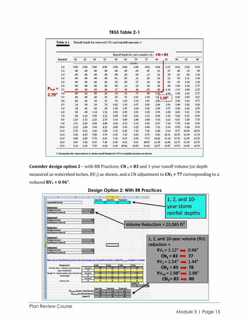
Interpolate from TR55 Table 2-1: Runoff Depth for Selected CN’s and Rainfall Amounts
OR
Use WIN-TR55 or any NRCS based stormwater hydrology software.
TR55 Figure 2-1
Plan Review Course
Module 5 | Page 15
TR55 Table 2-1
Consider design option 2 – with RR Practices: CN 1 = 83 and 1-year runoff volume (or depth
measured as watershed inches, RV1) as shown, and a CN adjustment to CN1 = 77 corresponding to a
reduced RV1 = 0.96”.
Design Option 2: With RR Practices
Plan Review Course
Module 5 | Page 16
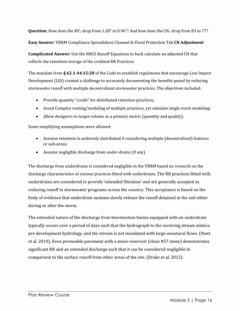
Question: How does the RV1 drop from 1.28” to 0.96”? And how does the CN1 drop from 83 to 77?
Easy Answer: VRRM Compliance Spreadsheet Channel & Flood Protection Tab CN Adjustment
Complicated Answer: Use the NRCS Runoff Equations to back calculate an adjusted CN that
reflects the retention storage of the credited RR Practices.
The mandate from § 62.1‐44.15:28 of the Code to establish regulations that encourage Low Impact
Development (LID) created a challenge to accurately documenting the benefits posed by reducing
stormwater runoff with multiple decentralized stormwater practices. The objectives included:
Provide quantity “credit” for distributed retention practices;
Avoid Complex routing/modeling of multiple practices, yet simulate single event modeling;
Allow designers to target volume as a primary metric (quantity and quality);
Some simplifying assumptions were allowed:
Assume retention is uniformly distributed if considering multiple (decentralized) features
or sub-areas;
Assume negligible discharge from under-drains (if any).
The discharge from underdrains is considered negligible in the VRRM based on research on the
discharge characteristics of various practices fitted with underdrains. The RR practices fitted with
underdrains are considered to provide ‘extended filtration’ and are generally accepted as
reducing runoff in stormwater programs across the country. This acceptance is based on the
body of evidence that underdrain systems slowly release the runoff detained in the soil either
during or after the storm.
The extended nature of the discharge from bioretention basins equipped with an underdrain
typically occurs over a period of days such that the hydrograph to the receiving stream mimics
pre development hydrology, and the stream is not inundated with large unnatural flows. (Hunt
et al. 2010). Even permeable pavement with a stone reservoir (clean #57 stone) demonstrates
significant RR and an extended discharge such that it can be considered negligible in
comparison to the surface runoff from other areas of the site. (Drake et al. 2012).

Plan Review Course
Module 5 | Page 17
Several theoretical methods for modifying the runoff hydrograph to account for retention storage
were considered:
1. Hydrograph Truncation
2. Hydrograph Scalar Multiplication
3. Precipitation Adjustment
4. Runoff Adjustment
5. Curve Number Adjustment
The VRRM utilizes the CN adjustment (Method No. 5 listed above) as a simple and conservative
method for crediting specific runoff reduction values toward peak flow reduction. The method
converts the total annual runoff reduction credit from all the BMPs in the drainage area from cubic
feet (or acre-feet) to watershed-inches of retention storage, and then uses the NRCS TR-55 runoff
equations 2-1 through 2-4 to derive a Curve Number adjustment that reflects the reduced runoff
depth. This new CN can then be used for computing the large storm peak discharge from the
drainage area for determining the storage volume needed for downstream channel or flood
protection requirements.
The total retention storage provided by RR practices, represented by the term R, is subtracted from
the runoff at the end of the storm event, providing a new value for S. A new CN is then back-
calculated from the new value of S using TR55 Equation 2-4.
While it is not easy to predict the absolute runoff hydrograph modification provided by reducing
stormwater runoff volumes, it is clear that reducing runoff volumes will have an impact on the
runoff hydrograph of a development site. Simple routing exercises have verified that this Curve
Number adjustment approach represents a conservative estimate of peak reduction.
Plan Review Course
Module 5 | Page 18
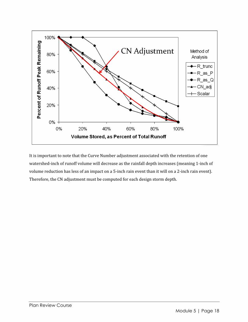
It is important to note that the Curve Number adjustment associated with the retention of one
watershed-inch of runoff volume will decrease as the rainfall depth increases (meaning 1-inch of
volume reduction has less of an impact on a 5-inch rain event than it will on a 2-inch rain event).
Therefore, the CN adjustment must be computed for each design storm depth.

Plan Review Course
Module 5 | Page 19
A graphical representation of how the curve number adjustment for the example provided above
can be graphically solved is provided below:
Back to the Design Example Option 2: with RR
The back-calculated adjusted CN based on the site (or drainage area) RR is shown in the figure
below. The water quality compliance has been verified in the VRRM Compliance spreadsheet Water
Quality Compliance tab, and the Channel & Flood Protection tab provides the corresponding CN
adjustment.
Energy Balance Computation of Allowable One-year Discharge
The pre- and post-developed condition hydrology and peak discharge is required in order to
complete the Energy Balance computation. Table 5-2 provides a summary of the Channel & Flood
Protection tab information, and includes the (previously computed) pre- and post-developed peak
discharge.

Plan Review Course
Module 5 | Page 20
Channel & Flood Protection Tab of the VRRM Compliance Spreadsheet
Table 5-2. 1-year Storm Channel & Flood Protection Tab Data Summary and Peak
Discharge

Plan Review Course
Module 5 | Page 21
The pre-developed peak discharge of 9 cfs is the in the Energy Balance equation:
In order to compare the benefit of implementing ESD and/or RR practices, the Energy Balance and
the volume of storage required will be computed reflecting both design options: with, and without
RR.
Without RR:
With RR
Note that the allowable peak discharge increases with the implementation of RR.
Also, as noted in 9VAC25-870-66:
Under no condition shall be greater than (i.e., the ratio of RVpre1 to RVpost1 cannot
be increased through ESD or RR practices to be greater than 1.25);
nor shall be required to be less than that calculated in the equation:

Plan Review Course
Module 5 | Page 22
Table 5-3. 1-year Storm Channel & Flood Protection Tab Data Summary & Peak Discharge
Note the double benefit of the VRRM: the peak discharge ( ) is reduced, and the allowable peak
discharge ( ) is increased
The designer can calculate the storage volume required with the developed condition peak inflow
(qi) and the allowable peak discharge or outflow (qo). Typically this will involve the use of
computer based Storage Indication or level pool routing software (or can be calculated using a
pencil and paper with the storage indication routing instructions found in the Blue Book).
Another option is the use of TR55 Figure 6-1. This plot provides an estimate of the level pool
routing continuity equation: Inflow – Outflow = ds/dt (the change in storage over time) based on
the design hydrology: the allowable peak outflow ( ), peak inflow ( ), and the volume of runoff
( or ). The method then solves for the required storage ( ).
The method provides an estimate and may be useful for quickly evaluating different design options
or reviewing plans. However, the method should only be used for final design if a 25% margin of
error is acceptable.

Plan Review Course
Module 5 | Page 23
The figure below provides the relevant values from the design example.
Without RR:
With RR:
Plan Review Course
Module 5 | Page 24
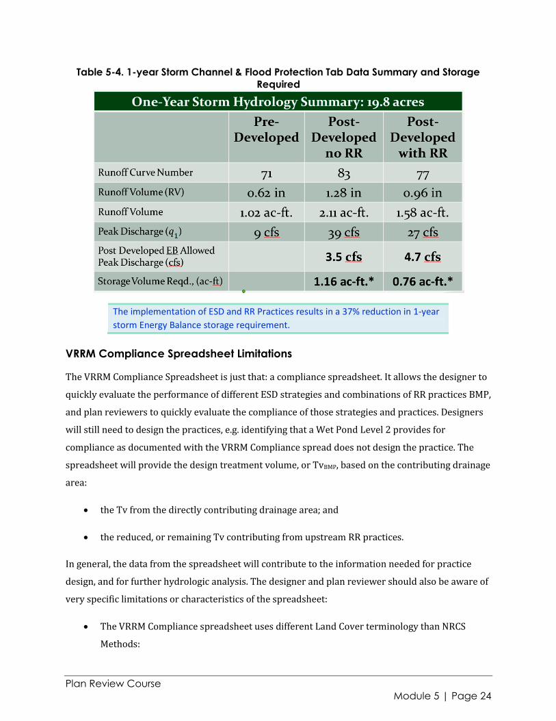
Table 5-4. 1-year Storm Channel & Flood Protection Tab Data Summary and Storage
Required
VRRM Compliance Spreadsheet Limitations
The VRRM Compliance Spreadsheet is just that: a compliance spreadsheet. It allows the designer to
quickly evaluate the performance of different ESD strategies and combinations of RR practices BMP,
and plan reviewers to quickly evaluate the compliance of those strategies and practices. Designers
will still need to design the practices, e.g. identifying that a Wet Pond Level 2 provides for
compliance as documented with the VRRM Compliance spread does not design the practice. The
spreadsheet will provide the design treatment volume, or TvBMP, based on the contributing drainage
area:
the Tv from the directly contributing drainage area; and
the reduced, or remaining Tv contributing from upstream RR practices.
In general, the data from the spreadsheet will contribute to the information needed for practice
design, and for further hydrologic analysis. The designer and plan reviewer should also be aware of
very specific limitations or characteristics of the spreadsheet:
The VRRM Compliance spreadsheet uses different Land Cover terminology than NRCS
Methods:
The implementation of ESD and RR Practices results in a 37% reduction in 1-year
storm Energy Balance storage requirement.

Plan Review Course
Module 5 | Page 25
o VRRM Forest/Open Space includes areas that may be considered meadow or
undisturbed (and unmanaged) pervious areas that are not necessarily forested;
o TR55 Open Space specifically refers to lawn or grass areas (cemeteries, parks, etc.)
and are assigned a CN equivalent to meadow. In the VRRM, these same areas would
be categorized as Managed Turf .
The VRRM Compliance spreadsheet is not a routing model. The VRRM compliance currency
is the reduction in annual volume and annual pollutant load; performance is not measured
for individual storms.
The VRRM spreadsheet does not reflect over-sized practice design
The spreadsheet is not a single event model or routing tool, i.e., additional storage volume
designed into a bioretention basin, or a permeable pavement storage reservoir will not be
reflected in any compliance calculations (water quality or CN adjustment) in the
spreadsheet. The designer will need to evaluate the benefit of the storage through standard
storage indication routing with a stage, storage, discharge curve developed for the
particular practice.
Multiple treatment trains can be difficult to compute and track when outflow diverges to
different downstream practices. When aggregated practices, e.g., several lots of simple
impervious disconnection, do not all flow to the same type of downstream practice, they
must be aggregated on separate DA tabs based on the common downstream practice.
The spreadsheet can’t track the aggregated volume from multiple treatment trains
displayed on separate DA tabs into a single downstream practice. The designer must track
the volume independently of the spreadsheet.
Plan Review Course
Module 5 | Page 26
5d. Flood Protection
Flood Protection criterion are based on an assessment of the current condition of the downstream
Stormwater Conveyance System: Does it currently experience localized flooding during the 10-year
24-hour storm event?
9VAC25-870-66.C: Flood Protection:
1. Discharges to areas that are not experiencing localized flooding must ensure that the
post-development peak flow rate from the 10-year 24-hour storm event is confined within
the stormwater conveyance system. Detention of stormwater or downstream
improvements may be incorporated into the approved land-disturbing activity to meet this
criterion, at the discretion of the VSMP authority.
2. Discharges to areas that are experiencing localized flooding must:
a. Confine the post-development peak flow rate from the 10-year 24-hour storm event
within the stormwater conveyance system to avoid the localized flooding. Detention
of stormwater or downstream improvements may be incorporated into the
approved land-disturbing activity to meet this criterion, at the discretion of the
VSMP authority; or
b. Releases a post-development peak flow rate for the 10-year 24-hour storm event
that is less than the predevelopment peak flow rate from the 10-year 24-hour storm
event. Downstream stormwater conveyance systems do not require any additional
analysis to show compliance with flood protection criteria if this option is utilized.
Localized flooding is defined in the regulations as smaller scale flooding that may occur outside of a
stormwater conveyance system, which may include high water, ponding, or standing water from
stormwater runoff, which is likely to cause property damage or unsafe conditions. Since this
definition may lead to subjective determinations of the presence (or lack of) localized flooding, the
VSMP Authority may identify areas to be subject to item 2.
In all cases, compliance with the requirement to keep the 10-year 24-hour peak flow rate confined
within the downstream stormwater conveyance system includes an allowance for VSMP Authority
discretion in allowing or excluding either on site detention or downstream channel improvements
as an option for demonstrating compliance.

Plan Review Course
Module 5 | Page 27
5e. Limits of Analysis
Channel Protection
The limits of analysis establish how far downstream the designer must verify the adequacy of the
Stormwater Conveyance System. The requirement to analyze the downstream system, and
therefore the criteria for how far downstream to carry the analysis applies only in cases where the
downstream Stormwater Conveyance System has been identified as being adequate to convey or
confine the post-development discharge as required, or the designer has implemented on site
detention and/or downstream improvements in order to establish adequacy. For Channel
Protection, this includes:
2-year peak discharge non-erosive velocity in a Manmade Stormwater Conveyance System,
or
2-year non-erosive velocity and 10-year containment in the system for Restored
Stormwater Conveyance System.
The designer must analyze the stormwater conveyance system using acceptable hydrologic and
hydraulic methodologies to verify that the applicable flow condition exists to the defined limit of
analysis.
Flood Protection
Downstream conveyance system analysis is applicable in the flood protection criteria only when
the designer has determined that the downstream Stormwater Conveyance System does not
experience localized flooding and the system will contain the post-development peak discharge as
required, or has implemented on site detention and/or downstream improvements in order to
alleviate the localized flooding.
The designer must analyze the stormwater conveyance system using acceptable hydrologic and
hydraulic methodologies to verify that the applicable flow condition exists to the defined limit of
analysis.
When the Energy Balance criterion is applied, no analysis of the downstream Stormwater Conveyance System is required.

Plan Review Course
Module 5 | Page 28
Limit of Analysis
The limit of analysis is a function of the site's contributing drainage area as follows:
a. The site's contributing drainage area is less than or equal to 1.0% of the total watershed
area draining to a point of analysis in the downstream stormwater conveyance system; or
b. Based on peak flow rate, the site's peak flow rate from the 10-year 24-hour storm event is
less than or equal to 1.0% of the existing peak flow rate from the 10-year 24-hour storm
event prior to the implementation of any stormwater quantity control measures; or
c. In the case of Flood Control, the stormwater conveyance system enters a mapped floodplain
or other flood-prone area, adopted by ordinance, of any locality.