module 4
DESCRIPTION
nrgTRANSCRIPT

Virtual Environments: Mushroom GillsTiffany Goh | 639188 | Semester 1 2013 | Group 12

Ideation - Mushroom GillsMushroom gills come in a variety of shapes in forms, but the one thing they all retain is the gentle wave-like structure of each cell. This unique aspect can be compared to fractal systems, as each each cell boundary converges and diverges with/from another. Using this information, patterns can be extracted by several different means. Symmetry As the method would suggest, a pattern by means of symmetry entails the extraction of a base element, in this case directly copying the outline of a single mushroom gill cell, and tessallating it on one side. Each base element need not be uniform in size. Repetition is used on the completed side in order to create a reflection of the pattern, providing symmetry. Movement To create movement, the base element chosen is a single contour within a larger one, emulating the folds and creases of the mushroom gill. The elements are repeated, scaled, and rotated, most pointing in a single direction to create dynamics. Balance To achieve balance, the entire image is divided into compartments that are proportionate to one another. A focal point is chosen for the compartment edges to converge. A base element is then chosen to fill in the compartments.
Symmetry Movement Balance

Ideation - Emerging FormsReviewing the previously established recipes, symmetry appeared to be the most appropriate for an adaptation into a paper model. The base element extracted was that of several curved X’s, reminiscent of the manner in which the mushroom gills converge and diverge from one another. Tessallating the X’s in various sizes would eventually form an intricate paper model which in turn casts a similar shadow. However, the curves and twists of such a pattern would prove to be far too difficult to apply to a form, as I realised during digitisation. I would eventually have to simplify it. The first of my proposed clay-model forms was very similar to my pattern, in that it is a series of X’s repeating and building upon each other to form a concave shape. The resulting form would closely resemble the paper model. The second was that of several cones pieced together in repetition, somewhat resembling a flower. While this could have reflected the mush-room’s part in nature, it was too much of a tangible concept and hence discarded. The third form was a spiral that would snake up around the arm, the waviness reflecting the mushroom cells.

Ideation - Precedent Studies
Architecture never fails to be a source of inspiration, especially for a project such as this one. One often has to think of how light will filter through the building and these three styles are what I hoped to somewhat achieve in my lantern. The Kuokkala church (first picture) boasts a series of uniform diamond shapes, each forming cells of their own. The diamond pattern, although geometrical and rigid, somehow appears organic. This is due to the gentle curvature of the roof ’s peak, which balances out the geomet-ric shapes and guides the eye to observe the symmetry each side has of each other. I did eventually integrate these factors into my lantern, although I had to undergo a few redesigns before truly understanding the purpose of my form. The Asmacati Shopping Center utilizes the macro patterning of leaves to form the roof. Scaling and rotation of each base element is used to replicate the scattered placement of leaves amongst themselves, hence enhancing the ‘natural’ experience. Scaling and rotation, a major part of my recipe, also contributed to my final lantern design. The Suzhou Science and Cultural Centre in China utilizes a layering system of randomly generated polygonic elements to create a facade of intricacy, yet it is a simple design. The entirety of the building is parabolic, again reiterating a natural, organic effect that is inherent in nature-based patterned architecture. The process of pattern creation is a simple matter of rotating each polygon; layering the interconnected polygons on top of each other creates a complex-looking matrix even though the design is fairly simple. Together, these three architectural designs form the basis of the pattern I wished to achieve in my lanter : A polygonic yet organic looking desgin that relates to my recipe (scaling, rotation, repetition) The lighting effect I wanted derives from layering and filtering, seen here with the C-Wall. The overlaying of the material casts a dense pattern of shadows on a surface. I sketched an idea of how my pattern could overlay, somewhat causing interference.

Ideation - Reading Responses Pattern Formation The formation process behind the mushroom gills arise from the autocatalytic chemical processes, in which the formation of the pattern depnds on a positive feedback system; each development of an element stimulates the development of the next element, like branching out trees. Although an exact chemical process of the pattern formation cannot be discerned, it is clear that the pattern formation is due to a mass interac-tion of each base element of the pattern,; the elements organise themselves and form from the interactions within themselves e.g the particles within cllusters of sand. The overall pattern resembles that of a fractal system, one of the most common pattern formations there are.
The transformation of the found pattern started with extrusion and repetition. The base element of the curve ‘X’ was repeated throughout to form each cell, and extruded to be in 3D formation. Repetition was further applied to the emergin forms model in the form of symmetry, as the initial pattern model was replicated and then mirrored and stuck to the model in a yin-yang sort of dynamc. Extrusion was done in a simi-lar way. The wavy edges of each structural element adhered to the organic nature of the mushroom gill, all in all forming a very organic looking model.

My initial plan was to use the flower-like form and further simplify it into its basic element - the cone. From there I could make multi-ple cones and attach them together to achieve the form I wanted. However, this shape was far too simple and it was difficult for the audience to grasp a connection to mushroom gills. Hence, I generated a few more shape ideas, taking care to reflect on my recipe and work from there. Out of clay and time, I resorted to sketching my ideas out. The two resultant ideas derived directly from my recipe: I simply extracted the ‘X’ base shape, and gave it a bloated form. From there I made my next shape by bending, achieving two downwards pointing arms. The curvature of the shape would provide the overlaying needed to achieve the desired lighting effect. The pattern I decided to use was a hexagonal, as it could easily resemble mushroom gills in polygonal form.. Problems arose in terms of the pattern’s disability to triangulate on the surface of the digitised model. Having used the ‘bend’ function on one of the models, (to the right), small creases and folds appeared on the model, making it impossible to apply a pattern to properly. Hence, I opted to use the unbent model. The same problems arose in disability to triangulate properly. Hence, I generated a new pattern, this time pre-triangulated.
Design - Refining

To the right are the scaled drawings used for the digitisation of the final model. They are the front view and the top view respectively. The top view clearly conveys the recipe of my pattern - using a wavy ‘X’ as a base element for the form. The front view emulates the random curves on the edges of each mushrom gill cell, and the middle is bloated to allow the diffusion of light when put in context. I have lost the actual digitised model, and only have for show the model which has already been patterned. I used profile sectional contouring to create the model. Using a pre-triangulated hexagonal shape, I applied it as a pattern on my form. This resulted in in easily distinguishable units on the model, the edges converging and diverging from each other like the mushroom gills.
Design - Digitisation
From then on, I utilised the ‘offset edges’ option under paneling tools to create holes of varying sizes and edge widths on the form. The main areas I aimed to place those holes were the middle and at the ends of where the middle inclines. This simulates the randomness of mushroom gill pattern - though the base elements are the same, they vary in size and angle. The subtle asymmetry of the model also reflects this.

Design - Readings
Composition Strategy To create my design, I maximised the use of the basic element, sticking them to each other to create a 3 dimensional sheet of cell structures. The main idea behind this was to emulate structural form of organic matters; the waviness of the edges avoid the sharpness and blockiness of inorganic geometry. The clay lantern model itself was shaped with complimenting the ‘organic’ look in mind. Curvatures were placed in a way that it also emulated the ‘wavy’ form, while in the three dimensional format. Another model idea was to use drew inspiration from the DNA double helix, integrating the base element as the whole composition of this. The third model idea utilised assemblage, it drew inspiration from the kusudama flower, which consists of separate conical shapes to form a single flower. Each flower could be put together to eventually form a ball. Another com-position strategy was used in mind while designing the models - Interference patterns. Two layers of patterns were intended to overlap and create a ‘shimmer effect’.
Abstraction and Reduction Abstraction is the consolidation of the convoluted infinity of the world to a minimalistic, describable point, whereas reduction is about find-ing a way to transform the entirety of the information without losing its meaning; paraphrasing, in a material sense. Abstraction was used in con-junction with the process analysis of module one, wherein the complex pattern was brought down to a simpler series of base elements. Reduction was used in that that series of base elements are intended to form a part of an emerging form; transforming it yet retaining the base information. It is continually used in the development of the models, as the shape and form is played around with, yet the information remains the same.

Fabrication - Unrolling I
I decided to jump straight into full-scale, full model prototyping to get a sense of what I’d need to change in terms of the entire model.
For the first unrolling, I decided to first separate a seam down the length of the model to serve as a 'zipper' later on. The rest of the unrolled strips would connect to this 'zipper'. This serves as a 'spine' for the model to be constructed around.There were tabs of 0.5 cm width on both sides of one unrolled strip. I used grasshopper's tabbing and dashed features to create the tabs and the dashed lines for folding.As the model had several faces and directions of folding, I figured that all fold lines should be dashed. Using grasshopper eased the need to indi-vidually select lines to dash.
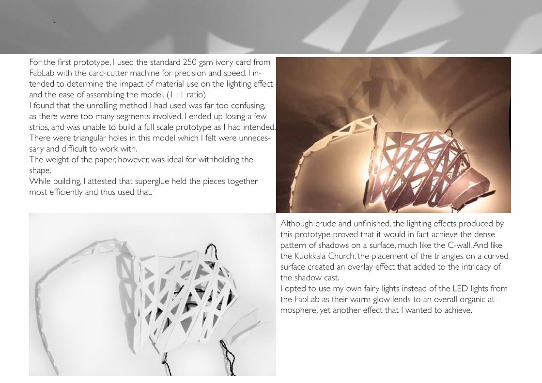
Fabrication - Prototype 1For the first prototype, I used the standard 250 gsm ivory card from FabLab with the card-cutter machine for precision and speed. I in-tended to determine the impact of material use on the lighting effect and the ease of assembling the model. (1 : 1 ratio)I found that the unrolling method I had used was far too confusing, as there were too many segments involved. I ended up losing a few strips, and was unable to build a full scale prototype as I had intended. There were triangular holes in this model which I felt were unneces-sary and difficult to work with.The weight of the paper, however, was ideal for withholding the shape. While building, I attested that superglue held the pieces together most efficiently and thus used that.
Although crude and unfinished, the lighting effects produced by this prototype proved that it would in fact achieve the dense pattern of shadows on a surface, much like the C-wall. And like the Kuokkala Church, the placement of the triangles on a curved surface created an overlay effect that added to the intricacy of the shadow cast. I opted to use my own fairy lights instead of the LED lights from the FabLab as their warm glow lends to an overall organic at-mosphere, yet another effect that I wanted to achieve.
Fabrication - Unrolling 2
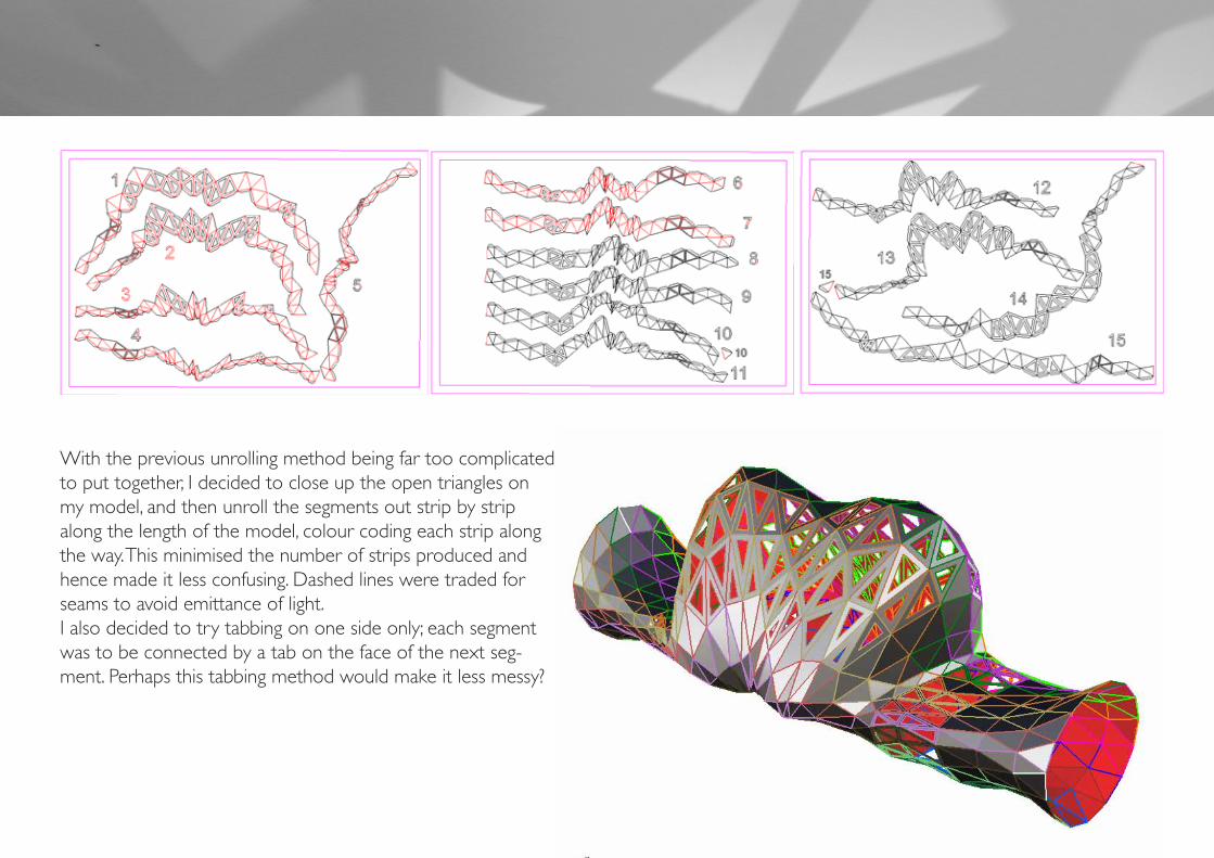
With the previous unrolling method being far too complicated to put together, I decided to close up the open triangles on my model, and then unroll the segments out strip by strip along the length of the model, colour coding each strip along the way. This minimised the number of strips produced and hence made it less confusing. Dashed lines were traded for seams to avoid emittance of light.I also decided to try tabbing on one side only; each segment was to be connected by a tab on the face of the next seg-ment. Perhaps this tabbing method would make it less messy?

Fabrication - Prototype III wanted to test out the black card on the card-cutter and used one of the two types available: the 200gsm (1 : 1 ratio)Unfortunately, the 200 gsm black card proved to be far too thin. The card-cutter ripped through the page on the first try. It became obvi-ous that I had to add a large number of seams to the edges in order for the paper to stay in place.When gluing the segments together, I realised that tabbing on only one side actually made it far messier than tabbing on both sides and letting the tab extrude inwards. In addition, the super-glue did not seem to stick properly on the thinner paper. I attribute this to the fact that it was more porous, letting the glue seep through before it can stick. As a result, I had to use craft glue, which resulted in an unsightly and messy prototype.Once again, I was unable to build a full-scale prototype due to the problems at hand.
Black paper, being more opaque, allowed clean cuts of light to shine through. No light filtered through the paper. However, the same ‘overlaying’ effect was achieved as with prototype 1. The cleaner cuts of light, however, didn’t seem to cast the same ‘organic’ atmosphere as the white paper. I resolved to once again use the 250gsm ivory card for my final model.

Fabrication - Final I
For convience, I decided to use the unrolling method for Prototype II on the final. The only thing I had changed was the inclusion of tabbing on both sides of each strip. As I continually worked on the model, however, I came to the realisation that the longer length of each strip prevented the entire model to bend correctly. Another problem arose fromthe leack of perforated lines. The seams were stiff, and only allowed a clean fold in one direction. My lantern requires both valleys and folds. The tabs were increasingly difficult to work with due to their small sizes. The superglue failed me as well. Due to the tremendous difficulty in building the model this way, I had to resort to building it out flat, and then forcing and bending it into shape. While doing this, however, I noticed how the tabs seemed to emulate the texture of the mushroom gills. I made a note to integrate this into future models.

Fabrication - Final I
Due to the problems arising during fabrication, Final 1 turned out incredibly messy and haphazardly made; fas-tened together by staplers as a last resort. However, what can be salvaged is the lighting effect. Although scattered and dissonant, it demonstrated exactly how the curvature of the model would create the densely patterned, intri-cate shadows on the wall. The lantern is meant to be held by the openings at either ends of its ‘arms. However, the manner in which it was built made it too flimsy to demonstrate on.

Fabrication - Readings
Architecture in the Digital Age - Design and ManufacturingDigital Fabrication Processes:●Two dimensional fabrication is a fabrication process which merely involves cutting (CNC cutting), involving two axis of motion for the cutters. These cutters can involve laser beams, water jets and plasma arcs. Laser cutters can precisely cut light-absorption material up to 5/8 inches cost- effectively, whereas a water jet can cut much thicker materials.●Subtractive fabrication involves the removal of a specified volume of material from an object. This usually utilises 3 axis: the X, Y and Z axis. It mills in these directions.●Additive Fabrication functions by adding layers of material on top of each other; also known as layered manufacturing, solid freeform fabrication, rapid prototyping or desktop manufacturing. The digital model is sliced into 2D layers before fabrication●Formative fabrication involves the use of heat and steam; applied to materials so that it can mould the desired shape via deformation.The use of the CNC card cutter has brought about several pros and cons. On the positive side, it greatly minimises the time needed to cut theshape of the unrolled model out, as opposed to the time that would have been needed with manual cutting. It also provided clean, precisely cutlines which would not have been achievable with manual cutting. However, the cardcutter tends to malfunction, and may fail to cut somesegments specified. It also has a tendency to tear or catch in cuts already made in the paper. This wastes a good amount of time and material.●
Digital fabrications: architectural and material techniques● The transition of 2D drawing to 3D digital drawing and fabrication put forward changes to innovation and expanded the boundaries of architectural form and construction. CAD programs were replaced with 3D modelling programs, and so the evolution of building designs began to occur over a relatively short period of time. Design projects such as William Massie’s concrete formwork, Greg Lynn’s typologies, and Bernard Cache’s surface manipulations, demonstrated the capabilities of digital fabrication for architects to control the building process as well as aesthetic aspects.Tessellation has been utilised for many generations. The patterns were used to filter light and define shapes, such as in mosaics and the stained glass windows of gothic cathedrals. Digital fabrication offered more variety and modulation for tessellation. Working digitally allowed a means to transition easily from 3D models to 2D vector line files, to manufacturing methods. This significantly reduced the labour processes needed due to the repetition involved in tessellation. It has become the result of using industrialised products e.g. tiles and bricks. Usually, in 3D modelling, a digital surface is first modelled, and the tessellation is applied to it.The fabrication process of my lantern is mainly based on tessellation. The ability of the triangle to tessellate made it ideal as the pattern for the model as it would produce no holes. I made a pattern out of triangles, which ‘triangulates’ the model when applied to it. This made unrolling easier as each strip could easily be defined.

Refinement of Final
Taking into account the encouragement from my tutors to integrate the tabbing as part of the lantern design, I set out to re-model my final. Instead of sticking the tabs together on the inside of the lantern, they would protrude fromt he surface of the lantern, emulating the texture of the mushroom gills. This enhances the segmented patterning on the lantern, an also lends a 3D aspect to it. As for unrolling, I re-visited the methods I had used in Prototype I. Without the open triangles this time, it would be less confusing. I also used Grasshopper once again to created perforated lines for the ability to fold alternately. Once again, I unzipped a strip along the length of the lantern, and unrolled the rest along the breadth. When putting the model together, this should held the form more sturdily than Proto-type II’s unrolling method. I also took care to colour code and name each strip accordingly.

Fabrication - Final II
Following more advice from my tutors, I used bull-clips to hold the tabs in place while I glued the others together. Instead of superglue, which caused the tabs to be transparent, I used PVC glue. The steps were simple: Simply join the unrolled strips to the ‘zipper’ strip, building them up layer by layer. I had also increased the length of the tabs to 1cm. This, coupled with seal-ing them together one the outer rather than inner surface of the lantern, proved to be a significantly easier task than Final I had been. The zipper’s tabs are on the inner surface, providing a channel for the lighting’s wiring to run through.

Final II
The end result: The addition of the tabbing increased the coolness factor by 50% yeah. One can truly see the relation to mushroom gills. This may be subjective, but it is also rather relaxing to run your fingers across the lantern’s surface to feel the tabbing’s texture. If mushroom gills were tough instead of soft, they’d feel like this


Exploded Isometric View
North-West Isometric View
The process is simple - The segments that have been pulled out represent how the lantern is put together. It is a simple linear progression of attaching each unrolled strip to the zipper, and to each other, mak-ing shure to bend it in the right ways and to attach to the right triangle.

Wiring and Lighting
The fairy lights were fed into the channel left by the zipper’s tabs and duct taped there. Extra lengths were taped to blind spots in the lantern e.g. the inner surface of where the inclining starts. The duct tape as painted over with white paint as an effort to better conceal them. The switch, when in use, is to be tucked in under the sleeves of the lantern holder, along with the remaining length of wire.

Wiring and Lighting
Overall, the lighting effect was neat and exactly as I wantedL Denselt patterned on to the surface and organic.

Lighting the Context
Lighting in context demonstrated: Holding the lantern up by the holes at either ends of its arms.

ReflectionThe last 10 weeks of this subject has truly shed light on how far digital technology has come. From 3D digitising to fabrication tools such as the card-cutter, the laser cutter and the 3D printer, technology has eased and accelerated the design process. They can be used to cre-ate scaled prototypes of an environment, or as we have done, to create art forms such as the lantern. Prototyping has become an integral part of design, as opposed to the simply building straight from schematics. It provides us with valuable feedback on how the design can be improved, how it could possibly impact the environment, what problems need to be rectified, and so on. However, I have realised that the fundamental components of the design process remains the same. No matter what, it is alway a cyclic process of looking back at the initial brief/recipe, and making sure that you have not gone off base.
Craft: a skill developed over time and in direct relationship to making and working with materials (Peggy Deamer and Phillip G. Bernstein, 2008). This has essentially been what the design process of my lantern has been about, with the added delight of digital modelling. My de-sign process has been a continual cycle of forming abstract constructs from the patterns of nature. I had mediated between various tools and materials as well as imagination to produce the techniques needed to form the end result – the lantern. Tools: The initial digitisation of the model and the subsequent use of the card cutter. And then: the testing of the materials (ivory card, black card, types of glue) and the subsequent adjustments to designs resulting from evaluations of prototypes. Risks: The design risk I was most concerned with was the aesthetics – Was the lantern reflecting my recipe? Did it please any eye or does it only please the beholder’s eye? As a result, I had to look back constantly on my recipe, and keep revising my final form design and method of construction. A health and safety risk to consider would have been the use of the Card-cutter tool. Although the card-cutter reduces risk to the amount of labour needed to complete the lantern, one must use it with care – long hair has to be tied back so it does not get caught, no limbs should be placed on the surface as the cutter cuts. But in an increasingly digitised working environment, risks are being reduced gradually. Aesthetics can be revised to satisfaction easily in the digital environment. Fabrication thereafter is mostly to evaluate the effectiveness of the design in full scale. The process of creating and re-creating using real-world materials is next to nullified.

BibliographyC-Wall - http://matsysdesign.com/tag/paper/
Poling, Clark (1987): Analytical Drawing In Kandisky’s Teaching at the Bauhaus Rizzoli, New York, pp. 107-122
Tooling / Aranda, Lasch. New York : Princeton Architectural Press, 2006 Ball, Philip (2012): Pattern Formation in Nature, AD: Architectural Design, Wiley, 82 (2), March, pp. 22-27 Scheurer, F. and Stehling, H. (2011): Lost in Parameter Space? IAD: Architectural Design, Wiley, 81 (4), July, pp. 70-79 Architecture in the Digital Age - Design and Manufacturing /Branko Kolarevic. Spon Press, London, c2003 Digital fabrications: architectural and material techniques / Lisa Iwamoto. New York : Princeton Architectural Press, c2009.
The third Industrial Revolution / Jeremy Rifkin. Palgrave Macmillan, C2011.pp107-126 Building the Future: Recasting Labor in Architecture/ Philip Bernstein, Peggy Deamer. Princeton Architectural Press. c2008. pp 38-42