modular panelboard system - steven engineering · pdf fileul 891 standard for dead-front...
TRANSCRIPT
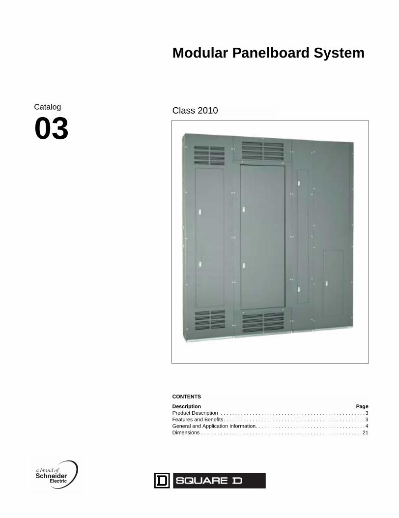
Modular Panelboard System
Class 2010
CONTENTS
Description PageProduct Description . . . . . . . . . . . . . . . . . . . . . . . . . . . . . . . . . . . . . . . . . . . . . . . . . . 3Features and Benefits. . . . . . . . . . . . . . . . . . . . . . . . . . . . . . . . . . . . . . . . . . . . . . . . . 3General and Application Information. . . . . . . . . . . . . . . . . . . . . . . . . . . . . . . . . . . . . . 4Dimensions . . . . . . . . . . . . . . . . . . . . . . . . . . . . . . . . . . . . . . . . . . . . . . . . . . . . . . . . 21
Catalog
03

Modular Panelboard SystemProduct Description
11/03
Modular Panelboard System
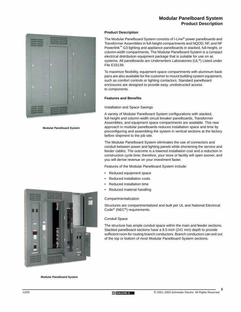
Modular Panelboard System
Product Description
The Modular Panelboard System consists of I-Line® power panelboards and Transformer Assemblies in full-height compartments and NQOD, NF, and NF Powerlink™ G3 lighting and appliance panelboards in stacked, full-height, or column-width compartments. The Modular Panelboard System is a compact electrical distribution equipment package that is suitable for use on ac systems. All panelboards are Underwriters Laboratories (UL®) Listed under File E33139.
To maximize flexibility, equipment space compartments with aluminum back pans are also available for the customer to mount building system equipment, such as comfort controls or lighting contactors. Standard panelboard enclosures are designed to provide easy, unobstructed access to components.
Features and Benefits
Installation and Space Savings
A variety of Modular Panelboard System configurations with stacked, full-height and column-width circuit breaker panelboards, Transformer Assemblies, and equipment space compartments are available. This new approach in modular panelboards reduces installation space and time by preconfiguring and assembling the system in vertical sections at the factory before shipment to the job site.
The Modular Panelboard System eliminates the use of connectors and conduit between power and lighting panels while shortening the service and feeder cables. The outcome is a lowered installation cost and a reduction in construction cycle time; therefore, your store or facility will open sooner, and you will derive revenue on your investment faster.
Features of the Modular Panelboard System include:
• Reduced equipment space
• Reduced installation costs
• Reduced installation time
• Reduced material handling
Compartmentalization
Structures are compartmentalized and built per UL and National Electrical Code® (NEC®) requirements.
Conduit Space
The structure has ample conduit space within the main and feeder sections. Stacked panelboard sections have a 9.5-inch (241 mm) depth to provide sufficient room for routing branch conductors. Branch conductors can exit out of the top or bottom of most Modular Panelboard System sections.
3© 2001–2003 Schneider Electric All Rights Reserved
Modular Panelboard SystemGeneral and Application Information
© 2001–2003 Schneider Electric All Rights Reserved4
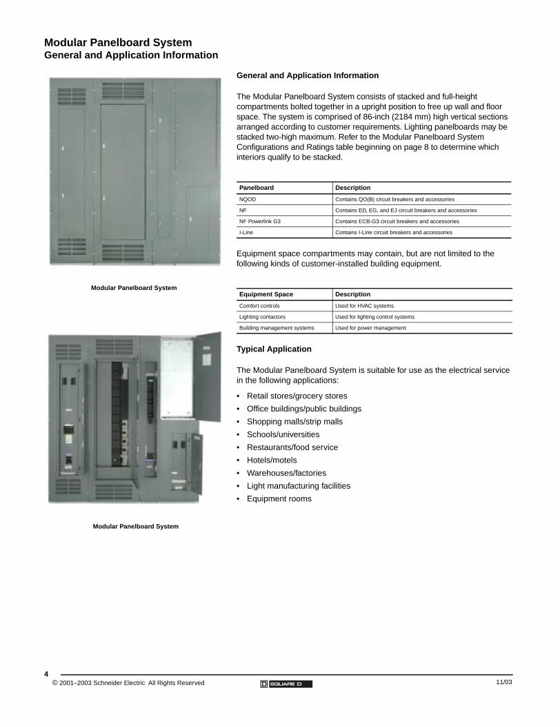
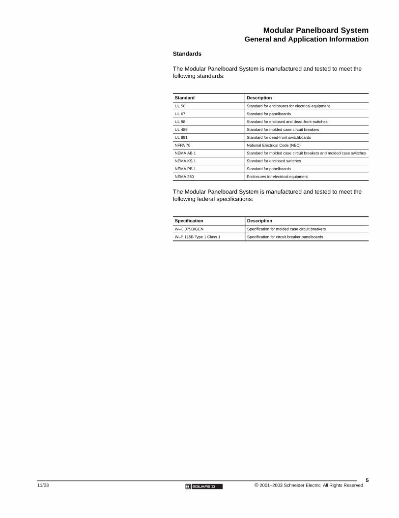
Modular Panelboard System
Modular Panelboard System
General and Application Information
The Modular Panelboard System consists of stacked and full-height compartments bolted together in a upright position to free up wall and floor space. The system is comprised of 86-inch (2184 mm) high vertical sections arranged according to customer requirements. Lighting panelboards may be stacked two-high maximum. Refer to the Modular Panelboard System Configurations and Ratings table beginning on page 8 to determine which interiors qualify to be stacked.
Equipment space compartments may contain, but are not limited to the following kinds of customer-installed building equipment.
Typical Application
The Modular Panelboard System is suitable for use as the electrical service in the following applications:
• Retail stores/grocery stores
• Office buildings/public buildings
• Shopping malls/strip malls
• Schools/universities
• Restaurants/food service
• Hotels/motels
• Warehouses/factories
• Light manufacturing facilities
• Equipment rooms
Panelboard Description
NQOD Contains QO(B) circuit breakers and accessories
NF Contains ED, EG, and EJ circuit breakers and accessories
NF Powerlink G3 Contains ECB-G3 circuit breakers and accessories
I-Line Contains I-Line circuit breakers and accessories
Equipment Space Description
Comfort controls Used for HVAC systems
Lighting contactors Used for lighting control systems
Building management systems Used for power management
11/03
Modular Panelboard SystemGeneral and Application Information
11/03
Standards
The Modular Panelboard System is manufactured and tested to meet the following standards:
The Modular Panelboard System is manufactured and tested to meet the following federal specifications:
Standard Description
UL 50 Standard for enclosures for electrical equipment
UL 67 Standard for panelboards
UL 98 Standard for enclosed and dead-front switches
UL 489 Standard for molded case circuit breakers
UL 891 Standard for dead-front switchboards
NFPA 70 National Electrical Code (NEC)
NEMA AB 1 Standard for molded case circuit breakers and molded case switches
NEMA KS 1 Standard for enclosed switches
NEMA PB 1 Standard for panelboards
NEMA 250 Enclosures for electrical equipment
Specification Description
W–C 375B/GEN Specification for molded case circuit breakers
W–P 115B Type 1 Class 1 Specification for circuit breaker panelboards
5© 2001–2003 Schneider Electric All Rights Reserved
Modular Panelboard SystemGeneral and Application Information
© 2001–2003 Schneider Electric All Rights Reserved6
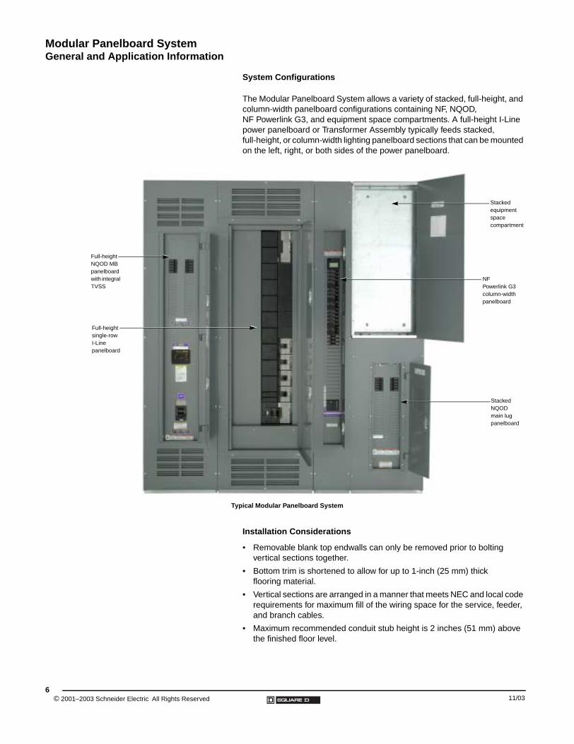
System Configurations
The Modular Panelboard System allows a variety of stacked, full-height, and column-width panelboard configurations containing NF, NQOD, NF Powerlink G3, and equipment space compartments. A full-height I-Line power panelboard or Transformer Assembly typically feeds stacked, full-height, or column-width lighting panelboard sections that can be mounted on the left, right, or both sides of the power panelboard.
Typical Modular Panelboard System
Full-height NQOD MB panelboard with integral TVSS
Full-height single-row I-Line panelboard
Stacked equipment space compartment
NF Powerlink G3 column-width panelboard
Stacked NQOD main lug panelboard
Installation Considerations
• Removable blank top endwalls can only be removed prior to bolting vertical sections together.
• Bottom trim is shortened to allow for up to 1-inch (25 mm) thick flooring material.
• Vertical sections are arranged in a manner that meets NEC and local code requirements for maximum fill of the wiring space for the service, feeder, and branch cables.
• Maximum recommended conduit stub height is 2 inches (51 mm) above the finished floor level.
11/03
Modular Panelboard SystemGeneral and Application Information
11/03
MPS Layout Guidelines
To comply with the NEC wiring space requirements, Modular Panelboard System layouts shall not exceed the following guidelines:
• Interiors rated 125 A maximum—Up to six sections (12 stacked interiors) on each side of a power panel
• Interiors rated 225/250 A maximum—Up to three sections (six stacked interiors) on each side of a power panel
• Interiors rated 225/250 A maximum—Up to six full-height interiors on each side of a power panel
• Interiors rated 400 A maximum—Up to four full-height interiors on each side of a power panel
• Interiors rated 600 A maximum—Up to two full-height interiors on each side of a power panel
Notes:
• Guidelines are based on:
— 3P4W interiors
— Copper conductors sized at 100% of the mains rating
— Type XHHW copper conductor
— Conductor sized per NEC table 310.16 (75 degree table)
• The installing contractor must comply with NEC wiring space requirements and local codes as interpreted by the jurisdiction having authority (local inspector).
• For short-circuit current ratings and interrupting ratings, refer to the appropriate panelboard catalog or the Switchboard/Panelboard Short-Circuit Current Ratings data bulletin.
MPS Shipping Configuration Options
• MPS Bolted Together (Ahead)—Tubs are shipped ahead to the job site completely bolted together in shipping splits up to 84 in. (2134 mm) wide. Interiors and trims are shipped at a later date.
• MPS Bolted Together (Ship Tog)—Tubs are bolted together at the factory in shipping splits up to 84 in. (2134 mm) wide. Tubs, interiors, and trims are shipped to the job site as one shipment. (Interiors and trims are not factory-installed.)
• MPS Bolted Together (Ship Asy)—Tubs, interiors, and trims are completely assembled at the factory and shipped to the job site in shipping splits up to 84 in. (2134 mm) wide.
NOTE: These systems also can be factory-wired when the power cable option is selected.
• MPS Individual Section (Ahead)—Tubs are shipped ahead to the job site as individual full-height sections. Interiors and trims are shipped at a later date. With this option, individual sections must be bolted together at the job site.
• MPS Individual Sections (Ship Tog)—Tubs are shipped from the factory as individual sections along with individual interiors and trims. With this option, individual sections must be bolted together at the job site. (Interiors and trims are not factory-installed.)
7© 2001–2003 Schneider Electric All Rights Reserved
Modular Panelboard SystemGeneral and Application Information
© 2001–2003 Schneider Elec8
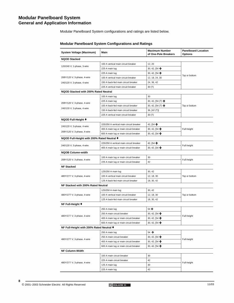
Modular Panelboard System configurations and ratings are listed below.
Modular Panelboard System Configurations and Ratings
System Voltage (Maximum) MainMaximum Number of One-Pole Breakers
Panelboard Location Options
NQOD Stacked
120/240 V; 1-phase, 3-wire100 A vertical main circuit breaker 12, 20
Top or bottom
225 A main lug 30, 42, [54 ❖ ]
208Y/120 V; 3-phase, 4-wire
240/120 V; 3-phase, 4-wire
225 A main lug 30, 42, [54 ❖ ]
100 A vertical main circuit breaker 12, 18, 24, 30
150 A back-fed main circuit breaker 24, 36, 42
225 A vertical main circuit breaker 30 (T)
NQOD Stacked with 200% Rated Neutral
208Y/120 V; 3-phase, 4-wire
240/120 V; 3-phase, 4-wire
100 A main lug 30
Top or bottom
225 A main lug 30, 42, [54 (T) ❖ ]
100 A back-fed main circuit breaker 30, 42, [54 (T) ❖ ]
150 A back-fed main circuit breaker 36, [42 (T)]
225 A vertical main circuit breaker 30 (T)
NQOD Full-Height ♦
240/120 V; 3-phase, 4-wire
208Y/120 V; 3-phase, 4-wire
225/250 A vertical main circuit breaker 42, [54 ❖ ]
Full-height400 A main lug or main circuit breaker 30, 42, [54 ❖ ]
600 A main lug or main circuit breaker 30, 42, [54 ❖ ]
NQOD Full-Height with 200% Rated Neutral ♦
240/120 V; 3-phase, 4-wire225/250 A vertical main circuit breaker 42, [54 ❖ ]
Full-height400 A main lug or main circuit breaker 30, 42, [54 ❖ ]
NQOB Column-width
208Y/120 V; 3-phase, 4-wire100 A main lug or main circuit breaker 30
Full-height225 A main lug or main circuit breaker 42
NF Stacked
480Y/277 V; 3-phase, 4-wire
125/250 A main lug 30, 42
Top or bottom100 A vertical main circuit breaker 12, 18, 30
125 A back-fed main circuit breaker 18, 30, 42
NF Stacked with 200% Rated Neutral
480Y/277 V; 3-phase, 4-wire
125/250 A main lug 30, 42
Top or bottom100 A vertical main circuit breaker 12, 18, 30
125 A back-fed main circuit breaker 18, 30, 42
NF Full-Height ♦
480Y/277 V; 3-phase, 4-wire
250 A main lug 54 ❖
Full-height250 A main circuit breaker 30, 42, [54 ❖ ]
400 A main lug or main circuit breaker 30, 42, [54 ❖ ]
600 A main lug or main circuit breaker 30, 42, [54 ❖ ]
NF Full-Height with 200% Rated Neutral ♦
480Y/277 V; 3-phase, 4-wire
250 A main lug 54 ❖
Full-height250 A main circuit breaker 30, 42, [54 ❖ ]
400 A main lug or main circuit breaker 30, 42, [54 ❖ ]
600 A main lug or main circuit breaker 30, 42, [54 ❖ ]
NF Column-Width
480Y/277 V; 3-phase, 4-wire
100 A main circuit breaker 30
Full-height225 A main circuit breaker 42
125 A main lug 30
225 A main lug 42
tric All Rights Reserved 11/03
Modular Panelboard SystemGeneral and Application Information
11/03
NF Powerlink G3 Stacked ❑ †
480Y/277 V; 3-phase, 4-wire
125 A back-fed main circuit breaker 42
Top or bottom100 A vertical main circuit breaker 30
225 A main lug 30, 42
NF Powerlink G3 Full-Height ♦ ❑ †
480Y/277 V; 3-phase, 4-wire
250 A main circuit breaker 30, 42, [54 ❖ ]
Full-height400 A main lug only or main circuit breaker 30, 42, [54 ❖ ]
600 A main lug only or main circuit breaker 30, 42, [54 ❖ ]
NF Powerlink G3 Column-Width ‡ ❑ †
480Y/277 V; 3-phase, 4-wire
100 A main circuit breaker 30
Full-height225 A main circuit breaker 42
125 A main lug 30
225 A main lug 42
I-Line
600 V
400–1200 A main lug99-inch and 108-inch mounting without main lug only kit
Full-height
600–1200 A main circuit breaker72-inch and 108-inch mounting without main circuit breaker
Single-Row I-Line
480Y/277 V; 3-phase, 4-wire800 A back-fed main circuit breaker or main lug
54-inch mounting without main circuit breaker or main lug only kit
Full-height
Equipment Space
43 x 20 x 9.5 inches ■
With hinged trim and aluminum back pan
Top or bottom
86 x 10 x 9.5 inches ■
Full-height86 x 20 x 9.5 inches ■
86 x 26 x 9.5 inches ■
Blank Space
43 x 20 x 9.5 inches ■ With blank covers and box studs; no back pan or elevating brackets Top or bottom
Wireway
86 x 10 x 9.5 inches ■ Hinged screw-on cover Full-height
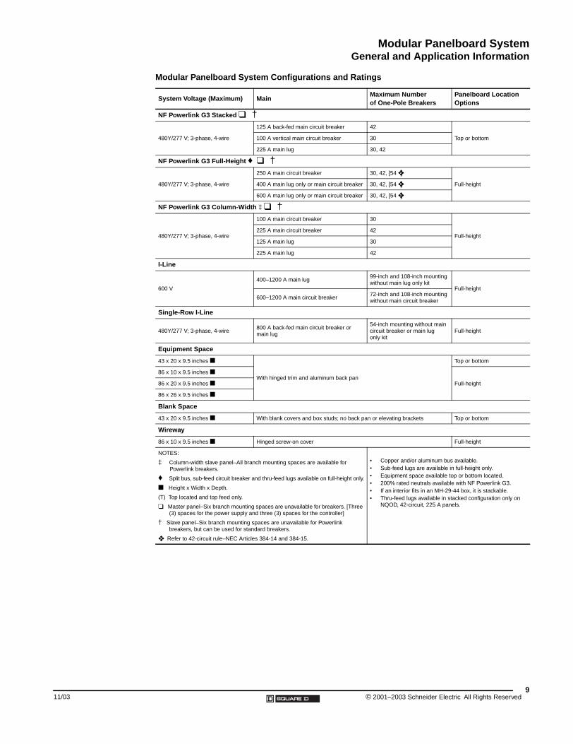
NOTES:
‡ Column-width slave panel–All branch mounting spaces are available for Powerlink breakers.
♦ Split bus, sub-feed circuit breaker and thru-feed lugs available on full-height only.
■ Height x Width x Depth.
(T) Top located and top feed only.
❑ Master panel–Six branch mounting spaces are unavailable for breakers. [Three (3) spaces for the power supply and three (3) spaces for the controller]
† Slave panel–Six branch mounting spaces are unavailable for Powerlink breakers, but can be used for standard breakers.
❖ Refer to 42-circuit rule–NEC Articles 384-14 and 384-15.
• Copper and/or aluminum bus available.• Sub-feed lugs are available in full-height only.• Equipment space available top or bottom located.• 200% rated neutrals available with NF Powerlink G3.• If an interior fits in an MH-29-44 box, it is stackable.• Thru-feed lugs available in stacked configuration only on
NQOD, 42-circuit, 225 A panels.
Modular Panelboard System Configurations and Ratings
System Voltage (Maximum) MainMaximum Number of One-Pole Breakers
Panelboard Location Options
9© 2001–2003 Schneider Electric All Rights Reserved
Modular Panelboard SystemGeneral and Application Information
© 2001–2003 Schneider Electric All Rights Reserved10
Elevating Brackets
Hole with Edge Guards for Cable Transition
Removable Bottom Plate
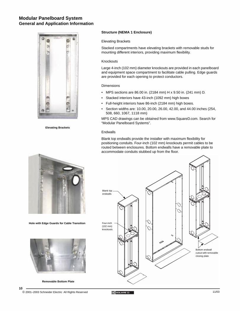
Structure (NEMA 1 Enclosure)
Elevating Brackets
Stacked compartments have elevating brackets with removable studs for mounting different interiors, providing maximum flexibility.
Knockouts
Large 4-inch (102 mm) diameter knockouts are provided in each panelboard and equipment space compartment to facilitate cable pulling. Edge guards are provided for each opening to protect conductors.
Dimensions
• MPS sections are 86.00 in. (2184 mm) H x 9.50 in. (241 mm) D.
• Stacked interiors have 43-inch (1092 mm) high boxes
• Full-height interiors have 86-inch (2184 mm) high boxes.
• Section widths are: 10.00, 20.00, 26.00, 42.00, and 44.00 inches (254, 508, 660, 1067, 1118 mm)
MPS CAD drawings can be obtained from www.SquareD.com. Search for “Modular Panelboard Systems”.
Endwalls
Blank top endwalls provide the installer with maximum flexibility for positioning conduits. Four-inch (102 mm) knockouts permit cables to be routed between enclosures. Bottom endwalls have a removable plate to accommodate conduits stubbed up from the floor.
Blank top endwalls
Four-inch (102 mm) knockouts
Bottom endwall cutout with removable closing plate
11/03
Modular Panelboard SystemGeneral and Application Information
11/03
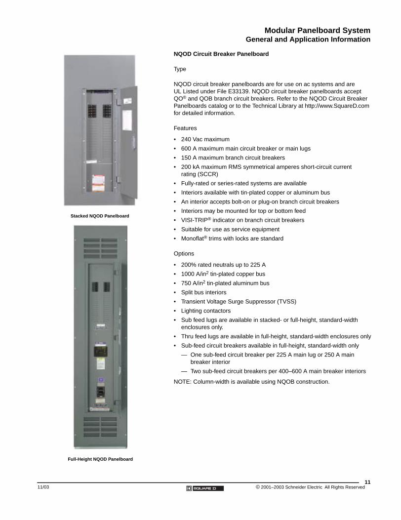
Stacked NQOD Panelboard
Full-Height NQOD Panelboard
NQOD Circuit Breaker Panelboard
Type
NQOD circuit breaker panelboards are for use on ac systems and are UL Listed under File E33139. NQOD circuit breaker panelboards accept QO® and QOB branch circuit breakers. Refer to the NQOD Circuit Breaker Panelboards catalog or to the Technical Library at http://www.SquareD.com for detailed information.
Features
• 240 Vac maximum
• 600 A maximum main circuit breaker or main lugs
• 150 A maximum branch circuit breakers
• 200 kA maximum RMS symmetrical amperes short-circuit current rating (SCCR)
• Fully-rated or series-rated systems are available
• Interiors available with tin-plated copper or aluminum bus
• An interior accepts bolt-on or plug-on branch circuit breakers
• Interiors may be mounted for top or bottom feed
• VISI-TRIP® indicator on branch circuit breakers
• Suitable for use as service equipment
• Monoflat® trims with locks are standard
Options
• 200% rated neutrals up to 225 A
• 1000 A/in2 tin-plated copper bus
• 750 A/in2 tin-plated aluminum bus
• Split bus interiors
• Transient Voltage Surge Suppressor (TVSS)
• Lighting contactors
• Sub feed lugs are available in stacked- or full-height, standard-width enclosures only.
• Thru feed lugs are available in full-height, standard-width enclosures only
• Sub-feed circuit breakers available in full-height, standard-width only
— One sub-feed circuit breaker per 225 A main lug or 250 A main breaker interior
— Two sub-feed circuit breakers per 400–600 A main breaker interiors
NOTE: Column-width is available using NQOB construction.
11© 2001–2003 Schneider Electric All Rights Reserved
Modular Panelboard SystemGeneral and Application Information
© 2001–2003 Schneider Electric All Rights Reserved12
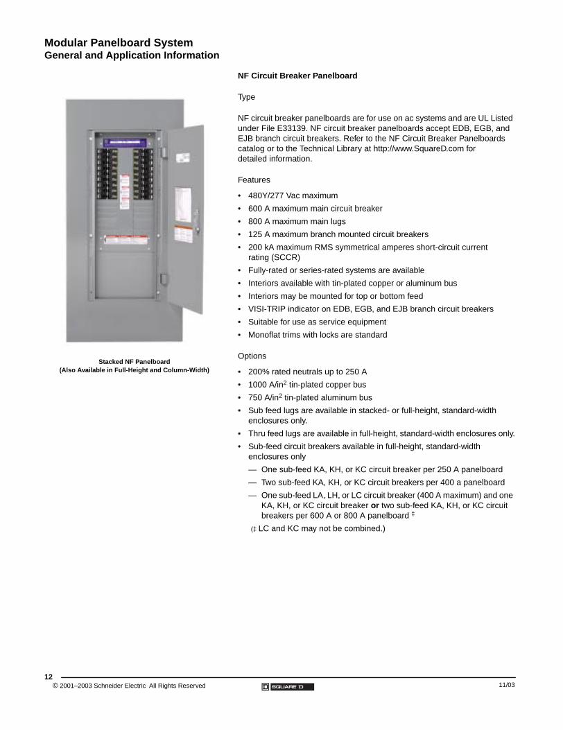
Stacked NF Panelboard(Also Available in Full-Height and Column-Width)
NF Circuit Breaker Panelboard
Type
NF circuit breaker panelboards are for use on ac systems and are UL Listed under File E33139. NF circuit breaker panelboards accept EDB, EGB, and EJB branch circuit breakers. Refer to the NF Circuit Breaker Panelboards catalog or to the Technical Library at http://www.SquareD.com for detailed information.
Features
• 480Y/277 Vac maximum
• 600 A maximum main circuit breaker
• 800 A maximum main lugs
• 125 A maximum branch mounted circuit breakers
• 200 kA maximum RMS symmetrical amperes short-circuit current rating (SCCR)
• Fully-rated or series-rated systems are available
• Interiors available with tin-plated copper or aluminum bus
• Interiors may be mounted for top or bottom feed
• VISI-TRIP indicator on EDB, EGB, and EJB branch circuit breakers
• Suitable for use as service equipment
• Monoflat trims with locks are standard
Options
• 200% rated neutrals up to 250 A
• 1000 A/in2 tin-plated copper bus
• 750 A/in2 tin-plated aluminum bus
• Sub feed lugs are available in stacked- or full-height, standard-width enclosures only.
• Thru feed lugs are available in full-height, standard-width enclosures only.
• Sub-feed circuit breakers available in full-height, standard-width enclosures only
— One sub-feed KA, KH, or KC circuit breaker per 250 A panelboard
— Two sub-feed KA, KH, or KC circuit breakers per 400 a panelboard
— One sub-feed LA, LH, or LC circuit breaker (400 A maximum) and one KA, KH, or KC circuit breaker or two sub-feed KA, KH, or KC circuit breakers per 600 A or 800 A panelboard ‡
(‡ LC and KC may not be combined.)
11/03
Modular Panelboard SystemGeneral and Application Information
11/03
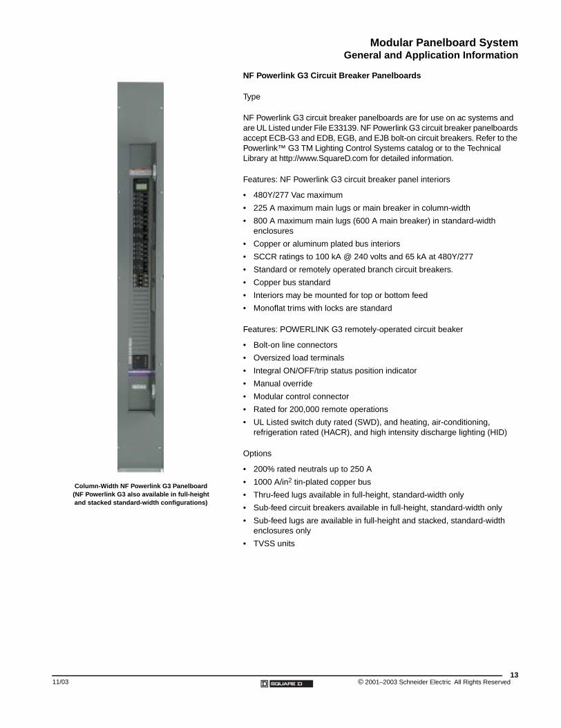
Column-Width NF Powerlink G3 Panelboard(NF Powerlink G3 also available in full-height and stacked standard-width configurations)
NF Powerlink G3 Circuit Breaker Panelboards
Type
NF Powerlink G3 circuit breaker panelboards are for use on ac systems and are UL Listed under File E33139. NF Powerlink G3 circuit breaker panelboards accept ECB-G3 and EDB, EGB, and EJB bolt-on circuit breakers. Refer to the Powerlink™ G3 TM Lighting Control Systems catalog or to the Technical Library at http://www.SquareD.com for detailed information.
Features: NF Powerlink G3 circuit breaker panel interiors
• 480Y/277 Vac maximum
• 225 A maximum main lugs or main breaker in column-width
• 800 A maximum main lugs (600 A main breaker) in standard-width enclosures
• Copper or aluminum plated bus interiors
• SCCR ratings to 100 kA @ 240 volts and 65 kA at 480Y/277
• Standard or remotely operated branch circuit breakers.
• Copper bus standard
• Interiors may be mounted for top or bottom feed
• Monoflat trims with locks are standard
Features: POWERLINK G3 remotely-operated circuit beaker
• Bolt-on line connectors
• Oversized load terminals
• Integral ON/OFF/trip status position indicator
• Manual override
• Modular control connector
• Rated for 200,000 remote operations
• UL Listed switch duty rated (SWD), and heating, air-conditioning, refrigeration rated (HACR), and high intensity discharge lighting (HID)
Options
• 200% rated neutrals up to 250 A
• 1000 A/in2 tin-plated copper bus
• Thru-feed lugs available in full-height, standard-width only
• Sub-feed circuit breakers available in full-height, standard-width only
• Sub-feed lugs are available in full-height and stacked, standard-width enclosures only
• TVSS units
13© 2001–2003 Schneider Electric All Rights Reserved

Modular Panelboard SystemGeneral and Application Information
© 2001–2003 Schneider Electric All Rights Reserved14
I-Line Panelboard Type HCR-U
I-Line® Circuit Breaker Power Distribution Panelboard
Type
I-Line® circuit breaker power distribution panelboards are for use on ac systems and are UL Listed under File E33139. I-Line circuit breaker power distribution panelboards have HCW, HCWM, and HCR-U interiors rated400–1200 A. Refer to the I-Line Circuit Breaker Panelboards catalog or to the Technical Library at http://www.SquareD.com for detailed information.
Features
• 600 Vac maximum
• 1200 A maximum main circuit breaker or main lugs
• UL Listed for use on ac systems up to 200 kA maximum RMS symmetrical amperes available fault current when using current limiting main or branch circuit breakers
• Fully-rated and series-rated systems
• Interiors available with plated aluminum or copper bus
• Interiors may be mounted for top or bottom feed
• Interior, front, and circuit breakers require only a screwdriver for installation
• Circuit breakers do not require any additional external mounting hardware
• Circuit breaker connections are “blow-on” type that draw the plug-on jaws together, providing a firmer grip under high level short-circuit conditions
• Well-suited for rearranging circuits
• Suitable for use as service equipment
Options
• 200% rated neutrals up to 600 A
• 1000 A/in2 tin-plated copper bus
• Micrologic® microprocessor and/or thermal magnetic main and branch circuit breakers
• Equipment ground fault protection available on main or branch circuit breaker
• Six-circuit QO plug-on distribution panel
• Sub-feed lugs through 1200 A
• Locks are available with optional door kits
11/03
Modular Panelboard SystemGeneral and Application Information
11/03
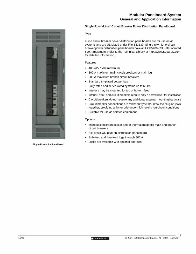
Single-Row I-Line Panelboard
Single-Row I-Line® Circuit Breaker Power Distribution Panelboard
Type
I-Line circuit breaker power distribution panelboards are for use on ac systems and are UL Listed under File E33139. Single-row I-Line circuit breaker power distribution panelboards have an HCP5486-8SU interior rated 800 A maximum. Refer to the Technical Library at http://www.SquareD.com for detailed information.
Features
• 480Y/277 Vac maximum
• 800 A maximum main circuit breakers or main lug
• 600 A maximum branch circuit breakers
• Standard tin-plated copper bus
• Fully-rated and series-rated systems up to 65 kA
• Interiors may be mounted for top or bottom feed
• Interior, front, and circuit breakers require only a screwdriver for installation
• Circuit breakers do not require any additional external mounting hardware
• Circuit breaker connections are “blow-on” type that draw the plug-on jaws together, providing a firmer grip under high level short-circuit conditions
• Suitable for use as service equipment
Options
• Micrologic microprocessor and/or thermal magnetic main and branch circuit breakers
• Six-circuit QO plug-on distribution panelboard
• Sub-feed and thru-feed lugs through 800 A
• Locks are available with optional door kits
15© 2001–2003 Schneider Electric All Rights Reserved
Modular Panelboard SystemGeneral and Application Information
© 2001–2003 Schneider Electric All Rights Reserved16
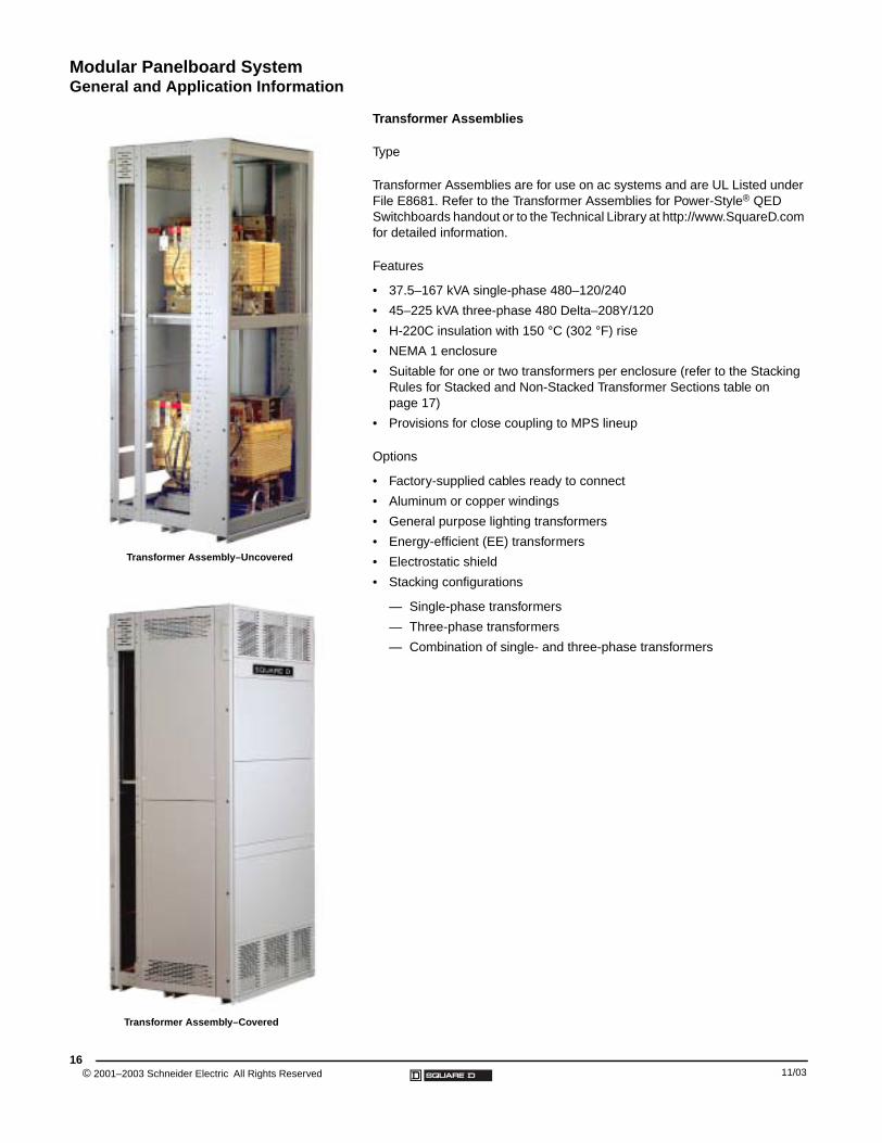
Transformer Assembly–Uncovered
Transformer Assembly–Covered
Transformer Assemblies
Type
Transformer Assemblies are for use on ac systems and are UL Listed under File E8681. Refer to the Transformer Assemblies for Power-Style® QED Switchboards handout or to the Technical Library at http://www.SquareD.com for detailed information.
Features
• 37.5–167 kVA single-phase 480–120/240
• 45–225 kVA three-phase 480 Delta–208Y/120
• H-220C insulation with 150 °C (302 °F) rise
• NEMA 1 enclosure
• Suitable for one or two transformers per enclosure (refer to the Stacking Rules for Stacked and Non-Stacked Transformer Sections table on page 17)
• Provisions for close coupling to MPS lineup
Options
• Factory-supplied cables ready to connect
• Aluminum or copper windings
• General purpose lighting transformers
• Energy-efficient (EE) transformers
• Electrostatic shield
• Stacking configurations
— Single-phase transformers
— Three-phase transformers
— Combination of single- and three-phase transformers
11/03
Modular Panelboard SystemGeneral and Application Information
11/03
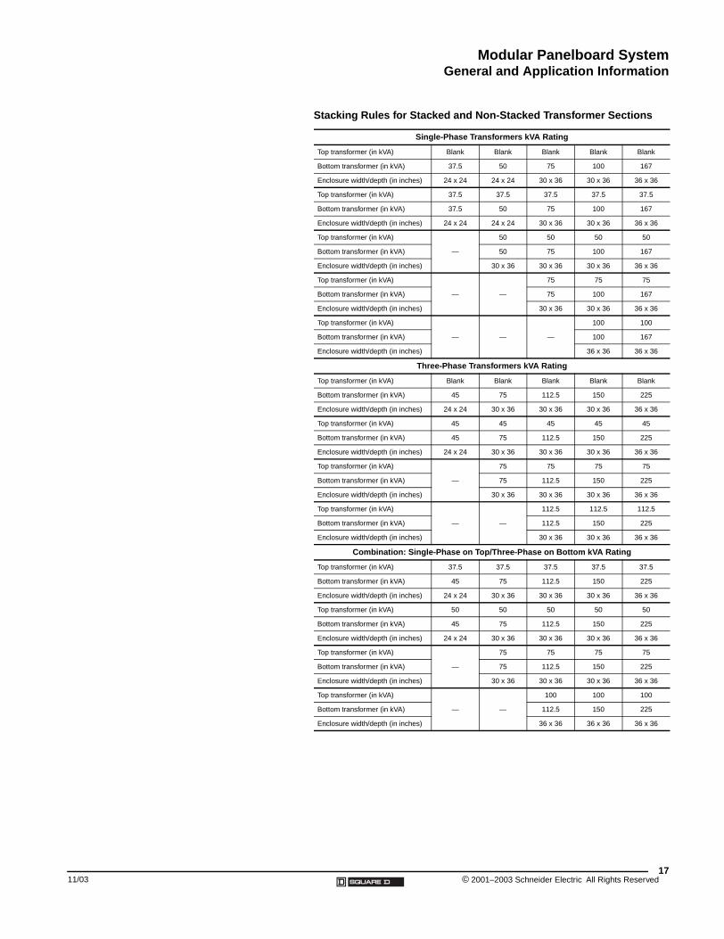
Stacking Rules for Stacked and Non-Stacked Transformer Sections
Single-Phase Transformers kVA Rating
Top transformer (in kVA) Blank Blank Blank Blank Blank
Bottom transformer (in kVA) 37.5 50 75 100 167
Enclosure width/depth (in inches) 24 x 24 24 x 24 30 x 36 30 x 36 36 x 36
Top transformer (in kVA) 37.5 37.5 37.5 37.5 37.5
Bottom transformer (in kVA) 37.5 50 75 100 167
Enclosure width/depth (in inches) 24 x 24 24 x 24 30 x 36 30 x 36 36 x 36
Top transformer (in kVA)
—
50 50 50 50
Bottom transformer (in kVA) 50 75 100 167
Enclosure width/depth (in inches) 30 x 36 30 x 36 30 x 36 36 x 36
Top transformer (in kVA)
— —
75 75 75
Bottom transformer (in kVA) 75 100 167
Enclosure width/depth (in inches) 30 x 36 30 x 36 36 x 36
Top transformer (in kVA)
— — —
100 100
Bottom transformer (in kVA) 100 167
Enclosure width/depth (in inches) 36 x 36 36 x 36
Three-Phase Transformers kVA Rating
Top transformer (in kVA) Blank Blank Blank Blank Blank
Bottom transformer (in kVA) 45 75 112.5 150 225
Enclosure width/depth (in inches) 24 x 24 30 x 36 30 x 36 30 x 36 36 x 36
Top transformer (in kVA) 45 45 45 45 45
Bottom transformer (in kVA) 45 75 112.5 150 225
Enclosure width/depth (in inches) 24 x 24 30 x 36 30 x 36 30 x 36 36 x 36
Top transformer (in kVA)
—
75 75 75 75
Bottom transformer (in kVA) 75 112.5 150 225
Enclosure width/depth (in inches) 30 x 36 30 x 36 30 x 36 36 x 36
Top transformer (in kVA)
— —
112.5 112.5 112.5
Bottom transformer (in kVA) 112.5 150 225
Enclosure width/depth (in inches) 30 x 36 30 x 36 36 x 36
Combination: Single-Phase on Top/Three-Phase on Bottom kVA Rating
Top transformer (in kVA) 37.5 37.5 37.5 37.5 37.5
Bottom transformer (in kVA) 45 75 112.5 150 225
Enclosure width/depth (in inches) 24 x 24 30 x 36 30 x 36 30 x 36 36 x 36
Top transformer (in kVA) 50 50 50 50 50
Bottom transformer (in kVA) 45 75 112.5 150 225
Enclosure width/depth (in inches) 24 x 24 30 x 36 30 x 36 30 x 36 36 x 36
Top transformer (in kVA)
—
75 75 75 75
Bottom transformer (in kVA) 75 112.5 150 225
Enclosure width/depth (in inches) 30 x 36 30 x 36 30 x 36 36 x 36
Top transformer (in kVA)
— —
100 100 100
Bottom transformer (in kVA) 112.5 150 225
Enclosure width/depth (in inches) 36 x 36 36 x 36 36 x 36
17© 2001–2003 Schneider Electric All Rights Reserved
Modular Panelboard SystemGeneral and Application Information
© 2001–2003 Schneider Electric All Rights Reserved18
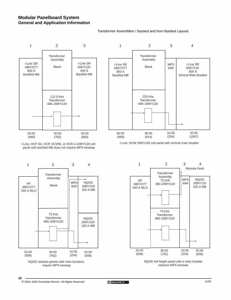
Transformer Assemblies / Stacked and Non-Stacked Layouts
I-Line SR 480Y/277
800 A Backfed MB
Transformer Assembly
BlankI-Line SR 208Y/120
400 A Backfed MB
112.5 kVa Transformer
480–208Y/120
I-Line, HCP-SU, HCP, HCWM, or HCR-U 208Y/120 volt panel with backfed MB does not require MPS wireway
26.00 (660)
30.00 (762)
26.00 (660)
1 2 3
I-Line SR 480Y/277
800 A Backfed MB
Transformer Assembly
BlankI-Line SR 208Y/120
600 A Vertical Main Breaker
225 kVa Transformer
480–208Y/120
26.00 (660)
MPS WW
36.00 (914)
10.00 (254)
42.00 (1067)
I-Line, HCW 208Y/120 volt panel with vertical main breaker
1 2 3 4
Transformer Assembly
Blank
75 kVa Transformer
480–208Y/120
MPS WW
10.00 (254)
NQOD 208Y/120 100 A MB
NQOD 208Y/120 100 A MB
NF 480Y/277
250 A MLO
20.00 (508)
20.00 (508)
30.00 (762)
NQOD stacked panels with main breakers require MPS wireway
1 2 3 4
75 kVa Transformer
480–208Y/120
MPS WW
10.00 (254)
NQOD 208Y/120 225 A MB
NF 480Y/277
400 A MLO
20.00 (508)
20.00 (508)
30.00 (762)
Transformer Assembly
75 kVA 480–208Y/120
NQOD full-height panel with a main breaker requires MPS wireway
Remote Feed1 2 3 4
11/03
Modular Panelboard SystemGeneral and Application Information
11/03
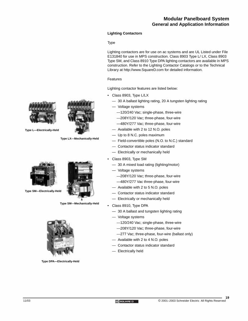
Type L—Electrically-Held
Type LX—Mechanically-Held
Type SM—Electrically-Held
Type SM—Mechanically-Held
Type DPA—Electrically-Held
Lighting Contactors
Type
Lighting contactors are for use on ac systems and are UL Listed under File E131840 for use in MPS construction. Class 8903 Type L/ LX, Class 8903 Type SM, and Class 8910 Type DPA lighting contactors are available in MPS construction. Refer to the Lighting Contactor Catalogs or to the Technical Library at http://www.SquareD.com for detailed information.
Features
Lighting contactor features are listed below:
• Class 8903, Type L/LX
— 30 A ballast lighting rating, 20 A tungsten lighting rating
— Voltage systems
—120/240 Vac; single-phase, three-wire
—208Y/120 Vac; three-phase, four-wire
—480Y/277 Vac; three-phase, four-wire
— Available with 2 to 12 N.O. poles
— Up to 8 N.C. poles maximum
— Field-convertible poles (N.O. to N.C.) standard
— Contactor status indicator standard
— Electrically or mechanically held
• Class 8903, Type SM
— 30 A mixed load rating (lighting/motor)
— Voltage systems
—208Y/120 Vac; three-phase, four-wire
—480Y/277 Vac three-phase, four-wire
— Available with 2 to 5 N.O. poles
— Contactor status indicator standard
— Electrically or mechanically held
• Class 8910, Type DPA
— 30 A ballast and tungsten lighting rating
— Voltage systems
—120/240 Vac; single-phase, three-wire
—208Y/120 Vac; three-phase, four-wire
—277 Vac; three-phase, four-wire (ballast only)
— Available with 2 to 4 N.O. poles
— Contactor status indicator standard
— Electrically held
19© 2001–2003 Schneider Electric All Rights Reserved
Modular Panelboard SystemGeneral and Application Information
© 2001–2003 Schneider Electric All Rights Reserved20
Options
Lighting contactor options are listed below:
• Factory-installed contactor options
— Lighting contactors (no wiring)
— Lighting contactors with lineside wiring (branch breakers to lineside)
— Lighting contactors with lineside and loadside wiring (branch breaker to lineside, loadside to terminal blocks)
• Lighting contactor enclosure dimensions
— 20 in. (W) x 43 in. (H) x 9.5 in. (D) (508 x 1092 x 241 mm) (stacked)
— 10 in. (W) x 86 in. (H) x 9.5 in. (D) (254 x 2184 x 241 mm) (full-height)
— 20 in. (W) x 86 in. (H) x 9.5 in. (D) (508 x 2184 x 241 mm) (full-height)
— 26 in. (W) x 86 in. (H) x 9.5 in. (D) (660 x 2184 x 241 mm) (full-height)
Refer to data bulletin 2010DB0201, Lighting Contactors and Terminal Blocks in Modular Panelboard System (MPS) and Integrated Power Center (IPC) or to the Panelboard Product Selector Help screens for panelboard/lighting contactor short-circuit current ratings.
Contactor Layout Guide
Use the following contactor layout guide to determine the correct MPS equipment space for your application.
• Class 8903, Type L; 8903 Type SM; or 8910 Type DPA electrically-held contactors with Type 9080 GR6/GC6 terminal blocks:
— Eight (8) contactors maximum in a stacked 20 in. (508 mm) (W) x 43 in. (1092 mm) (H) equipment space
— Eight (8) contactors maximum in one (1) full-height 10 in. (254 mm) (W) x 86 in. (2184 mm) (H) equipment space
— 16 contactors maximum in one (1) full-height 20 in. (508 mm) (W) x 86 in. (2184 mm) (H) equipment space
— 16 contactors maximum in one (1) full-height 26 in. (660 mm) (W) x 86 in. (2184 mm) (H) equipment space
• Class 8903, Type LX or Class 8903, Type SM mechanically-held contactors with Type 9080 GR6/GC6 terminal blocks:
— Six (6) contactors maximum in a stacked 20 in. (508 mm) (W) x 43 in. (1092 mm) (H) equipment space
— Six (6) contactors maximum in one (1) full-height 10 in. (254 mm) (W) x 86 in. (2184 mm) (H) equipment space
— 12 contactors maximum in one full-height 20 in. (508 mm) (W) x 86 in. (2184 mm) (H) equipment space
— 12 contactors maximum in one full-height 26 in. (660 mm) (W) x 86 in. (2184 mm) (H) equipment space
11/03
Modular Panelboard SystemDimensions
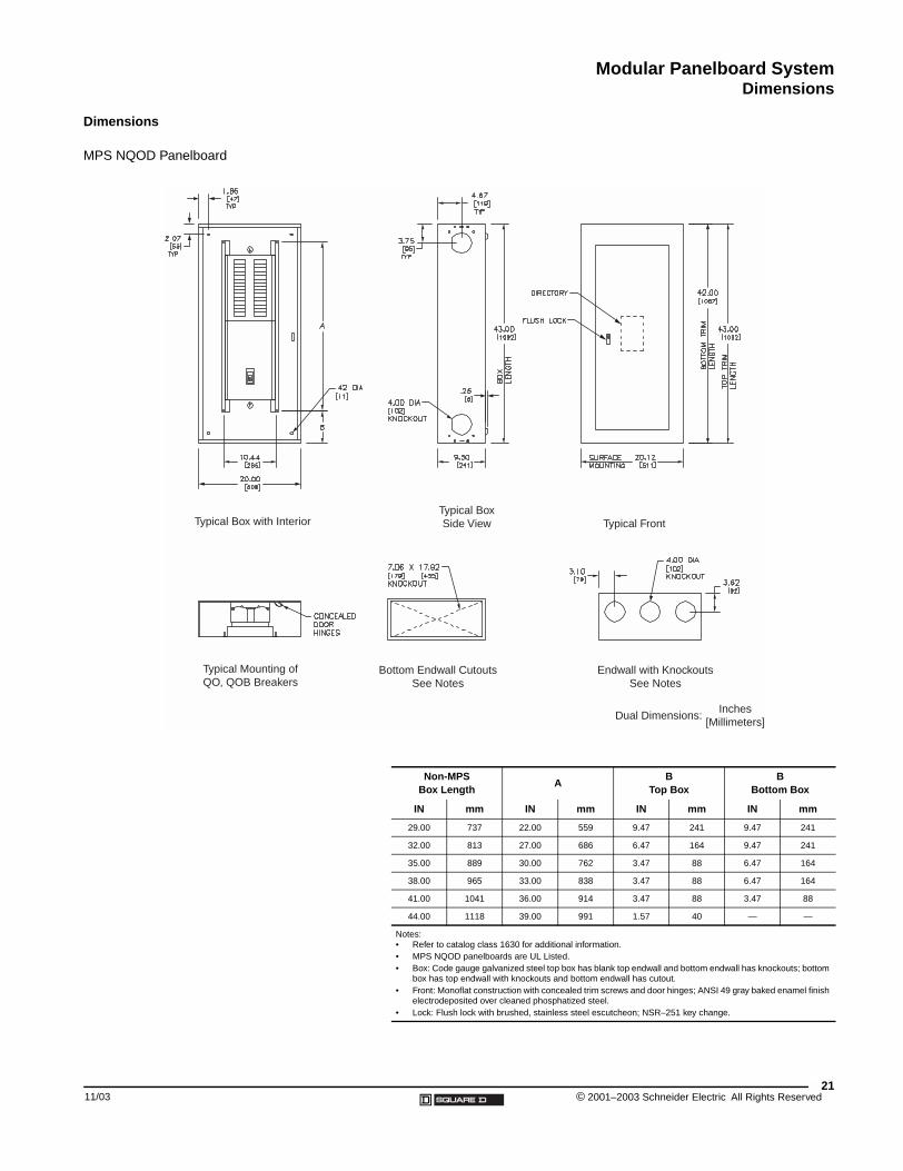
Dimensions
MPS NQOD Panelboard
Typical Box with InteriorTypical Box Side View Typical Front
Typical Mounting of QO, QOB Breakers
Bottom Endwall Cutouts See Notes
Endwall with Knockouts See Notes
Dual Dimensions:Inches
[Millimeters]
11/03
Non-MPS Box Length
AB
Top BoxB
Bottom Box
IN mm IN mm IN mm IN mm
29.00 737 22.00 559 9.47 241 9.47 241
32.00 813 27.00 686 6.47 164 9.47 241
35.00 889 30.00 762 3.47 88 6.47 164
38.00 965 33.00 838 3.47 88 6.47 164
41.00 1041 36.00 914 3.47 88 3.47 88
44.00 1118 39.00 991 1.57 40 — —
Notes:• Refer to catalog class 1630 for additional information.• MPS NQOD panelboards are UL Listed.• Box: Code gauge galvanized steel top box has blank top endwall and bottom endwall has knockouts; bottom
box has top endwall with knockouts and bottom endwall has cutout.• Front: Monoflat construction with concealed trim screws and door hinges; ANSI 49 gray baked enamel finish
electrodeposited over cleaned phosphatized steel.• Lock: Flush lock with brushed, stainless steel escutcheon; NSR–251 key change.
21© 2001–2003 Schneider Electric All Rights Reserved
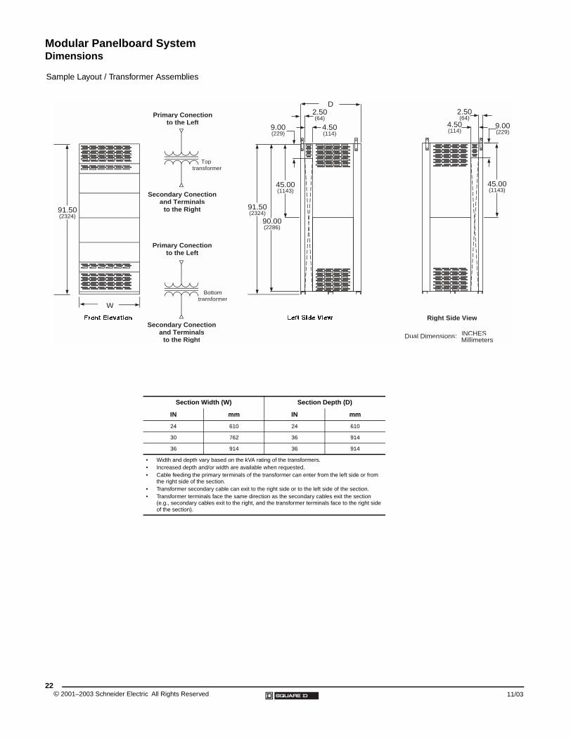
Modular Panelboard SystemDimensions
Sample Layout / Transformer Assemblies
Primary Conectionto the Left
Secondary Conectionand Terminals
to the Right
Primary Conectionto the Left
Secondary Conectionand Terminals
to the Right
91.50(2324)
Dual Dimensions: INCHESMillimeters
91.50(2324)
90.00(2286)
45.00(1143)
9.00(229)
2.50(64)
4.50(114)
4.50(114)
2.50(64)
9.00(229)
45.00(1143)
Right Side View
W
D
Top transformer
Bottomtransformer
© 2001–2003 Schneider Ele22
Section Width (W) Section Depth (D)
IN mm IN mm
24 610 24 610
30 762 36 914
36 914 36 914
• Width and depth vary based on the kVA rating of the transformers.• Increased depth and/or width are available when requested.• Cable feeding the primary terminals of the transformer can enter from the left side or from
the right side of the section.• Transformer secondary cable can exit to the right side or to the left side of the section.• Transformer terminals face the same direction as the secondary cables exit the section
(e.g., secondary cables exit to the right, and the transformer terminals face to the right side of the section).
ctric All Rights Reserved 11/03


Catalog No. 2010CT0001R11/03 November 2003 © 2001–2003 Schneider Electric All Rights Reserved Replaces 2010CT0001R4/02 , dated 04/02.
Schneider Electric252 North TippecanoePeru, IN 47970 USA1-888-SquareD(1-888-778-2733)www.SquareD.com
Schneider Canada Inc.19 Waterman Avenue, M4B 1 Y2Toronto, Ontario1-800-565-6699www.schneider-electric.ca