modulair - fullbucket.de · modulair manual page 5 architecture modulair is a modular synthesizer...
TRANSCRIPT

ModulAirPolyphonic Modular Synthesizer
Version 1.0
© 2018-2019 by Björn Arlt @ Full Bucket Musichttp://www.fullbucket.de/music
VST is a trademark of Steinberg Media Technologies GmbH
Windows is a registered trademark of Microsoft Corporation
The Audio Units logo is a trademark of Apple Computer, Inc.

ModulAir Manual Page 2
Table of Contents
Introduction....................................................4Acknowledgments............................................4Architecture....................................................5Common Section.............................................6Modules.........................................................7
Oscillators Modules..............................................8Oscillator...............................................................8Dual Oscillator........................................................8Linear FM Oscillator.................................................9Formant Oscillator...................................................9Wavetable Oscillator..............................................10Dual Noise............................................................10
Filter Modules...................................................11Filter (Ladder).......................................................11Filter (K35)...........................................................11Filter (Comb)........................................................12Resonators...........................................................12St.Filter (Ldr.), St.Filter (K35), St.Filter (Comb), St.Resonators.......................................................13Equalizer..............................................................13Parametric Equalizer..............................................13
Amplifier Modules..............................................14Amplifier..............................................................14Mixer...................................................................14Signal Processor....................................................15Blender................................................................15
Processor Modules.............................................16Ring Modulator......................................................16Audio S/H.............................................................16Hilbert.................................................................17Bit Reducer...........................................................18Dual Saturator......................................................18
Modulator Modules............................................19Envelope..............................................................19Dual Envelope.......................................................19Quad Envelope......................................................20Dual Linear Envelope.............................................20LFO.....................................................................21Dual LFO..............................................................21Sample & Hold......................................................22
Sequencer Modules............................................23Sequencer............................................................23Beat Sequencer.....................................................23Sequential Switch..................................................24Audio Switch.........................................................24
Effect Modules..................................................25BBD Delay............................................................25Dual Delay Line.....................................................25Reverb.................................................................26
Tool Modules.....................................................27Voltage Processor..................................................27LAG/Adder............................................................27

ModulAir Manual Page 3
Sample Delay.......................................................28Modulation Signal Delay/M2G..................................28Gate Tools............................................................29
Miscellaneous Functionality..............................30Options Menu...................................................30MIDI Learn.......................................................30Custom Tuning..................................................30MIDI CC Sources...............................................30
Frequently Asked Questions.............................31

ModulAir Manual Page 4
IntroductionModulAir is a polyphonic modular software synthesizer plug-in for Microsoft Windows (VST) and Apple macOS (VST/AU). It is written in native C++ code for high performance even on “lighter” systems. The main features are:
● Fully modular architecture● Up to 18 modules per patch● Polyphonic (up to 64 voices) and monophonic Master modules● External signal processing possible● TUN/SCL/KBM micro-tuning file import● MIDI Learn – all parameters can be controlled by MIDI CC● Double precision audio processing● Plug-in supports Windows and macOS (32 bit and 64 bit)
ModulAir is (although now officially released) a work in progress with only a bunch of quirky presets and a lousy documentation. Note that I am constantly adding modules and stuff to it.
If you experience any problems that you cannot resolve by following the suggestions in the Frequently Asked Questions: Please send a mail to [email protected] . Please tell me what OS (Windows, MacOSX, 32 or 64 bit) and Host/DAW software you are using! Also send me a mail if you have suggestions or comments.
And please note: I will not add “virtual cables” dangling on the screen. Instead I will stay with the “plug” concept that I already use with my other plug-ins (FB-3X00 series, blooo, scrooo, qyooo, etc.).
Acknowledgments First I wanted to thank Cockos and Oli Larkin for developing and maintaining the
WDL(-OL)/IPlug framework, and Laurent Bergman for his French manuals.
The TUN/SCL file handling source code is adapted from Mark Henning at https://www.mark-henning.de/.
Furthermore a BIG THANKS to Tim Stinchcombe and Will Pirkle for their in-depth analysis of the K35 filter chip.
Last not least another THANK YOU! to Manfred Hasenfus and to the KVR Audio community, especially to bjporter, BlackWinny, Halomusic, Dee.P.Tree, fmr, andmartin_l.

ModulAir Manual Page 5
ArchitectureModulAir is a modular synthesizer that can hold up to 18 modules. Each module can either be a polyphonic Voice module or a monophonic Master module:
• Voice modules are used for the individual synthesizer voices (typically oscillators, filters, modulators etc.).
• Master modules are used for overall sound processing of all voices (e.g. effects like delay or reverb).
However, there is no limitation in the way that modules are used – it is perfectly OK tocreate a (in this case necessarily monophonic) synthesizer completely out of Master modules. And it is also possible to add Reverb as a Voice module (which then of course will only reverberate the individual voice). The following diagram shows the signal flow of ModulAir.
The voice signals generated by the Voice modules are shaped by individual ADSR envelope generators and then summed up to form the Voices Sum stereo signal. This signal along with an external input signal can be used to feed the Master modules. The final output can then be selected from the output of a Master module (if applicable) or the Voices Sum signal.
While audio signals cannot be sent directly from Voice modules to Master modules or vice versa, it is possible to send modulation and/or gate/trigger signals from Master modules to Voice modules. This way one can create global LFOs or sequencers and trigger sources.
Voice Modules(polyphonic)
VoicesADSR + Sum
Master Modules(monophonic)
MasterSum
External Input
ModulAir Manual Page 6
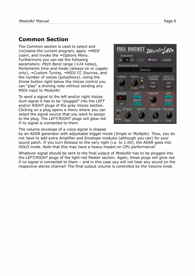
Common SectionThe Common section is used to select and(re)name the current program, apply MIDI Learn, and invoke the Options Menu.Furthermore you can set the followingparameters: Pitch Bend range (±24 notes), Portamento time and mode (always on or Legatoonly), Custom Tuning, MIDI CC Sources, andthe number of voices (polyphony). Using the Drone button right below the Voices control youcan “play” a droning note without sending anyMIDI input to ModulAir.
To send a signal to the left and/or right VoicesSum signal it has to be “plugged” into the LEFTand/or RIGHT plugs of the gray Voices section.Clicking on a plug opens a menu where you canselect the signal source that you want to assignto the plug. The LEFT/RIGHT plugs will glow redif no signal is connected to them.
The volume envelope of a voice signal is shapedby an ADSR generator with adjustable trigger mode (Single or Multiple). Thus, you do not have to add extra Amplifier and Envelope modules (although you can) for your sound patch. If you turn Release to the very right (i.e. to 1.00), the ADSR goes into HOLD mode. Note that this may have a heavy impact on CPU performance!
Whatever signal should be sent to the final output of ModulAir has to be plugged into the LEFT/RIGHT plugs of the light-red Master section. Again, these plugs will glow red if no signal is connected to them – and in this case you will not hear any sound on therespective stereo channel! The final output volume is controlled by the Volume knob.

ModulAir Manual Page 7
ModulesCurrently there are 44 different module types available of which 18 different modules can be used per program at the same time. The module types are divided into the following groups:
• Oscillators (6 types)
• Filters (6 + 4 stereo versions)
• Amplifiers (4)
• Processors (5)
• Modulators (7)
• Sequencers (4)
• Effects (3)
• Tools (5)
You can add/change a module by clicking the header of the respective slot and selecting the desired module from a context menu. If you right-click the header you can move the module to a different slot. Alternatively you can drag & drop the moduleto the new location. If you drag it to the Common section, its outputs will be automatically plugged to the output plugs of the respective section (Voice or Master). Of course this will only work for modules that feature at least one audio output (like oscillators, amplifiers or filters).
Clicking on the top-left button (labelled with “V” for Voice or “M” for Master) will change a Voice module to a Master module or vice versa.
To patch a module plug just click on the plug symbol and select the required source signal from the context menu. Audio signals are color-coded in blue, modulation signals in yellow, and Gate signals in orange.

ModulAir Manual Page 8
Oscillators Modules
Oscillator
The Oscillator module is a standard band-limited oscillator withthe following parameters:
Waveform: Selects the current waveform (Sine, Saw or Pulse).
Sync: Source oscillator for Hard Sync.
Pitch: Shifts the frequency up or down in semitones by amaximum of two octaves.
Tune: Fine tuning in cents of plus/minus one semitone.
Reset: Gate/trigger source for resetting the oscillator’s phase.
Phase: Phase (in degrees) to which the oscillator will be reset.
(Phase) Mod: Source for reset phase modulation.
Shape: Shape of the waveform. If Pulse is selected this willcorrespond to pulse width modulation.
(Shape) Mod: Source and amount for shape modulation.
(Frequency) Mod: Source and amount for frequency modulation.
The Oscillator module has one audio and one Sync output.
Dual Oscillator
The Dual Oscillator module features two band-limited oscillators A and B with the following parameters:
Waveform A/B: Selects the current waveform (Sine, Saw or Pulse).
Pitch A/B: Shifts the frequency up or down in semitones by amaximum of two octaves.
Tune A/B: Fine tuning in cents of plus/minus one semitone.
Shape A/B: Shape of the waveform. If Pulse is selected this willcorrespond to pulse width modulation.
Mod A/B: Source and amount for frequency modulation.
The Dual Oscillator module has two audio and two Sync outputs(one per oscillator A and B).

ModulAir Manual Page 9
Linear FM Oscillator
The Linear FM Oscillator module is a band-limited oscillator thatallows for linear frequency modulation. It has the followingparameters:
Waveform: Selects the current waveform (Sine, Saw or Pulse).
Sync: Source oscillator for Hard Sync.
Pitch: Shifts the frequency up or down in semitones by amaximum of two octaves.
Tune: Fine tuning in cents of plus/minus one semitone.
Reset: Gate/trigger source for resetting the oscillator’s phase.
Phase: Phase (in degrees) to which the oscillator will be reset.
(Phase) Mod: Source for reset phase modulation.
Lin. FM: Source and amount for linear FM.
(Lin. FM) Mod: Source and amount for linear FM modulation.
(Frequency) Mod: Source and amount for frequency modulation.
The Linear FM Oscillator module has one audio and one Sync output.
Formant Oscillator
The Formant Oscillator module is an oscillator that generateswaveforms with an adjustable spectrum relative to the basefrequency or a fixed frequency. It has the following parameters:
Mode: Selects the oscillator mode.
• Fixed: The spectrum will be centered at a fixed frequency.
• Partial: The spectrum will be centered relative to a partial ofthe base frequency.
• Ring: The spectrum will be centered relative to a fractionalmultiple of the base frequency.
(Formant Frequency): Fixed frequency/partial/multiple of thecenter of the spectrum.
Spread: Adjusts the bandwidth of the generated spectrum.
(Formant Frequency) Mod: Source and amount for Formantfrequency modulation.
Pitch: Shifts the frequency up or down in semitones by a maximum of two octaves.
Tune: Fine tuning in cents of plus/minus one semitone.
(Frequency) Mod: Source and amount for frequency modulation.
The Formant Oscillator module has one audio and one Sync output.
ModulAir Manual Page 10
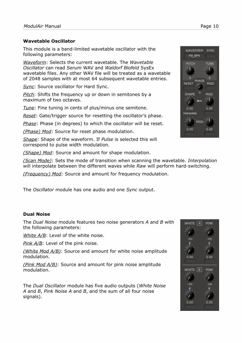
Wavetable Oscillator
This module is a band-limited wavetable oscillator with thefollowing parameters:
Waveform: Selects the current wavetable. The WavetableOscillator can read Serum WAV and Waldorf Blofeld SysExwavetable files. Any other WAV file will be treated as a wavetableof 2048 samples with at most 64 subsequent wavetable entries.
Sync: Source oscillator for Hard Sync.
Pitch: Shifts the frequency up or down in semitones by amaximum of two octaves.
Tune: Fine tuning in cents of plus/minus one semitone.
Reset: Gate/trigger source for resetting the oscillator’s phase.
Phase: Phase (in degrees) to which the oscillator will be reset.
(Phase) Mod: Source for reset phase modulation.
Shape: Shape of the waveform. If Pulse is selected this willcorrespond to pulse width modulation.
(Shape) Mod: Source and amount for shape modulation.
(Scan Mode): Sets the mode of transition when scanning the wavetable. Interpolation will interpolate between the different waves while Raw will perform hard-switching.
(Frequency) Mod: Source and amount for frequency modulation.
The Oscillator module has one audio and one Sync output.
Dual Noise
The Dual Noise module features two noise generators A and B withthe following parameters:
White A/B: Level of the white noise.
Pink A/B: Level of the pink noise.
(White Mod A/B): Source and amount for white noise amplitudemodulation.
(Pink Mod A/B): Source and amount for pink noise amplitudemodulation.
The Dual Oscillator module has five audio outputs (White NoiseA and B, Pink Noise A and B, and the sum of all four noisesignals).
ModulAir Manual Page 11
Filter Modules
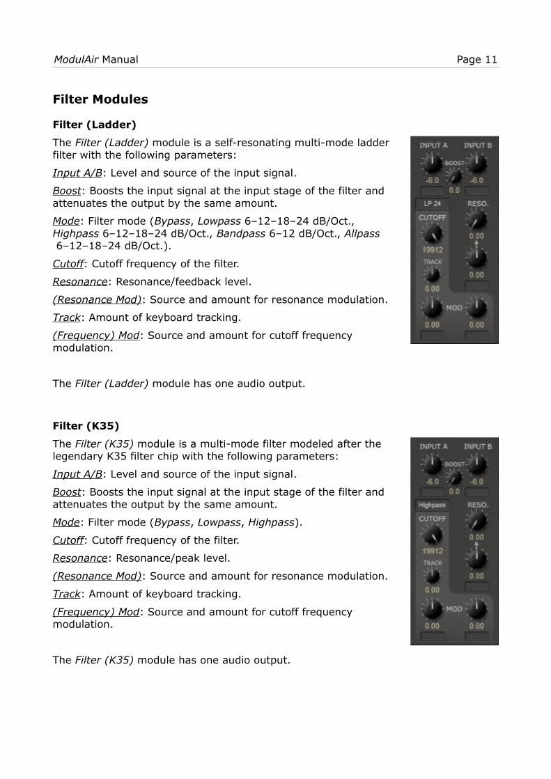
Filter (Ladder)
The Filter (Ladder) module is a self-resonating multi-mode ladderfilter with the following parameters:
Input A/B: Level and source of the input signal.
Boost: Boosts the input signal at the input stage of the filter andattenuates the output by the same amount.
Mode: Filter mode (Bypass, Lowpass 6–12–18–24 dB/Oct., Highpass 6–12–18–24 dB/Oct., Bandpass 6–12 dB/Oct., Allpass 6–12–18–24 dB/Oct.).
Cutoff: Cutoff frequency of the filter.
Resonance: Resonance/feedback level.
(Resonance Mod): Source and amount for resonance modulation.
Track: Amount of keyboard tracking.
(Frequency) Mod: Source and amount for cutoff frequencymodulation.
The Filter (Ladder) module has one audio output.
Filter (K35)
The Filter (K35) module is a multi-mode filter modeled after thelegendary K35 filter chip with the following parameters:
Input A/B: Level and source of the input signal.
Boost: Boosts the input signal at the input stage of the filter andattenuates the output by the same amount.
Mode: Filter mode (Bypass, Lowpass, Highpass).
Cutoff: Cutoff frequency of the filter.
Resonance: Resonance/peak level.
(Resonance Mod): Source and amount for resonance modulation.
Track: Amount of keyboard tracking.
(Frequency) Mod: Source and amount for cutoff frequencymodulation.
The Filter (K35) module has one audio output.
ModulAir Manual Page 12
Filter (Comb)
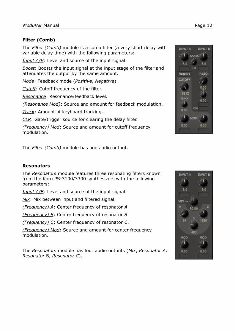
The Filter (Comb) module is a comb filter (a very short delay withvariable delay time) with the following parameters:
Input A/B: Level and source of the input signal.
Boost: Boosts the input signal at the input stage of the filter andattenuates the output by the same amount.
Mode: Feedback mode (Positive, Negative).
Cutoff: Cutoff frequency of the filter.
Resonance: Resonance/feedback level.
(Resonance Mod): Source and amount for feedback modulation.
Track: Amount of keyboard tracking.
CLR: Gate/trigger source for clearing the delay filter.
(Frequency) Mod: Source and amount for cutoff frequencymodulation.
The Filter (Comb) module has one audio output.
Resonators
The Resonators module features three resonating filters knownfrom the Korg PS-3100/3300 synthesizers with the followingparameters:
Input A/B: Level and source of the input signal.
Mix: Mix between input and filtered signal.
(Frequency) A: Center frequency of resonator A.
(Frequency) B: Center frequency of resonator B.
(Frequency) C: Center frequency of resonator C.
(Frequency) Mod: Source and amount for center frequencymodulation.
The Resonators module has four audio outputs (Mix, Resonator A, Resonator B, Resonator C).

ModulAir Manual Page 13
St.Filter (Ldr.), St.Filter (K35), St.Filter (Comb), St.Resonators
These four modules are stereo versions of the filter modules mentioned above.
Left/Right: Level and source of the left/right input signal.
For additional parameters see the respective “mono” modules.
The stereo modules have exactly two audio outputs (Left and Right).
Equalizer
The Equalizer module is a 10-stage graphic equalizer with thefollowing parameters:
Input A/B: Level and source of the input signal.
(Mono/Stereo): Switch from mono (A+B) to stereo input (A|B).
Frequency Bands (16kHz – 30Hz): Level of the respectivefrequency band in decibel.
The Equalizer module has two audio outputs.
Parametric EQ
The Parametric EQ module is a 5-stage parametric equalizer withthe following parameters:
Input A/B: Level and source of the input signal.
(Mono/Stereo): Switch from mono (A+B) to stereo input (A|B).
Frequency 1 – 5 (16kHz – 16000Hz): Frequency of the respectiveband in Hertz.
Level 1 – 5: Level of the respective frequency band in decibel (-18to +18 dB).
The Parametric EQ module has two audio outputs.
ModulAir Manual Page 14
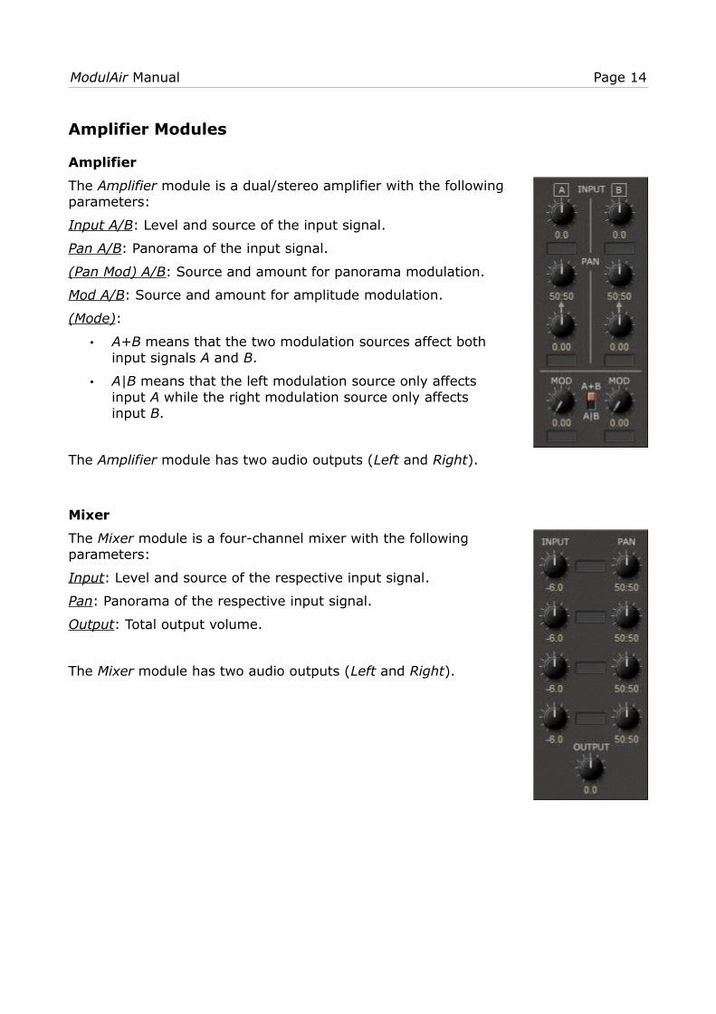
Amplifier Modules
Amplifier
The Amplifier module is a dual/stereo amplifier with the followingparameters:
Input A/B: Level and source of the input signal.
Pan A/B: Panorama of the input signal.
(Pan Mod) A/B: Source and amount for panorama modulation.
Mod A/B: Source and amount for amplitude modulation.
(Mode):
• A+B means that the two modulation sources affect bothinput signals A and B.
• A|B means that the left modulation source only affectsinput A while the right modulation source only affectsinput B.
The Amplifier module has two audio outputs (Left and Right).
Mixer
The Mixer module is a four-channel mixer with the followingparameters:
Input: Level and source of the respective input signal.
Pan: Panorama of the respective input signal.
Output: Total output volume.
The Mixer module has two audio outputs (Left and Right).

ModulAir Manual Page 15
Signal Processor
The Signal Processor module features four amplifiers with thefollowing parameters:
Input A/B/C/D: Source of the input signal.
Mod A/B/C/D: Source and amount for amplitude modulation.
The Signal Processor module has five audio outputs (Signal A to Dand Summed Output).
Blender
The Blender module features two amplifiers that can blendbetween two signal inputs. It has the following parameters:
Inputs A/B: Source of the two input signals of each section.
(Blend) A/B: Source and amount for blending between the twoinputs of each blender section.
The Blender module has two audio outputs (Blender A and B).

ModulAir Manual Page 16
Processor Modules
Ring Modulator
The Ring Modulator module features two Ring modulators with thefollowing parameters:
Input A1/A2: Sources of the inputs for Ring modulator A.
Input B1/B2: Sources of the inputs for Ring modulator B.
Amount: Intensity of Ring modulation.
Mod: Source and amount for Ring intensity modulation.
The Ring Modulator module has two audio outputs (RingModulator A and B).
Audio S/H
The Audio S/H module resamples the incoming signal at adifferent rate. It has the following parameters:
Input: Source of the input.
Tonality: Typically, the resampled signal is constructed of band-limited pulse steps. With this control the steps can be graduallychanged to a saw-like shape.
(Fixed Frequency On/Off): Switches between keyboard-controlledand fixed frequency.
(Fixed Frequency): Fixed resample frequency (when fixedfrequency is on).
Pitch: Shifts the resample frequency up or down in semitones by amaximum of two octaves (when fixed frequency is off).
Tune: Fine tuning of the resample frequency in cents ofplus/minus one semitone (when fixed frequency is off).
Mod: Source and amount for resample frequency modulation.
The Audio S/H module has one audio output.
ModulAir Manual Page 17
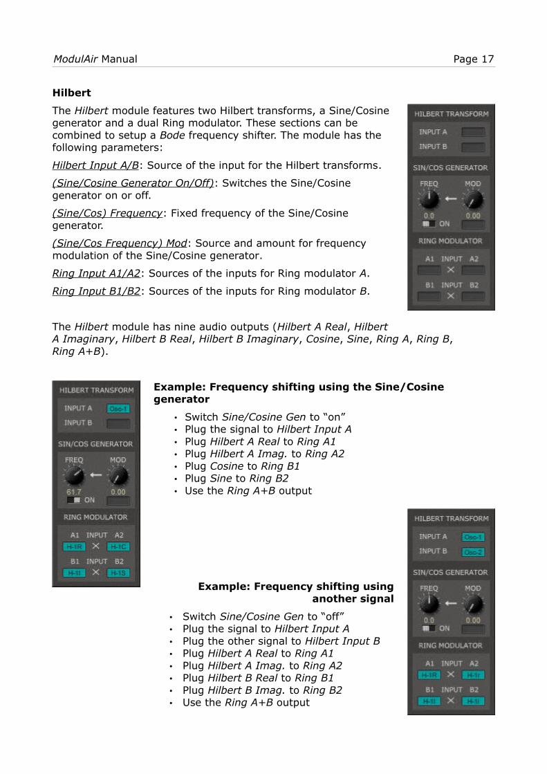
Hilbert
The Hilbert module features two Hilbert transforms, a Sine/Cosinegenerator and a dual Ring modulator. These sections can becombined to setup a Bode frequency shifter. The module has thefollowing parameters:
Hilbert Input A/B: Source of the input for the Hilbert transforms.
(Sine/Cosine Generator On/Off): Switches the Sine/Cosinegenerator on or off.
(Sine/Cos) Frequency: Fixed frequency of the Sine/Cosinegenerator.
(Sine/Cos Frequency) Mod: Source and amount for frequencymodulation of the Sine/Cosine generator.
Ring Input A1/A2: Sources of the inputs for Ring modulator A.
Ring Input B1/B2: Sources of the inputs for Ring modulator B.
The Hilbert module has nine audio outputs (Hilbert A Real, HilbertA Imaginary, Hilbert B Real, Hilbert B Imaginary, Cosine, Sine, Ring A, Ring B, Ring A+B).
Example: Frequency shifting using the Sine/Cosine generator
• Switch Sine/Cosine Gen to “on”• Plug the signal to Hilbert Input A• Plug Hilbert A Real to Ring A1• Plug Hilbert A Imag. to Ring A2• Plug Cosine to Ring B1• Plug Sine to Ring B2• Use the Ring A+B output
Example: Frequency shifting usinganother signal
• Switch Sine/Cosine Gen to “off”• Plug the signal to Hilbert Input A• Plug the other signal to Hilbert Input B• Plug Hilbert A Real to Ring A1• Plug Hilbert A Imag. to Ring A2• Plug Hilbert B Real to Ring B1• Plug Hilbert B Imag. to Ring B2• Use the Ring A+B output

ModulAir Manual Page 18
Bit Reducer
The Bit Reducer module features two bit reducers with thefollowing parameters:
Input A/B: Source and level of the input.
Scale A/B: Scale (pre-amplification) of the input signal.
Bits A/B: Number of (virtual) bits of reduction.
Mod A/B: Source and amount for bit reduction modulation.
The Bit Reducer module has two audio outputs (A and B).
Dual Saturator
The Dual Saturator module features two saturation/distortion unitswith the following parameters:
Input A/B: Source and level of the input.
Drive A/B: Amount of saturation/distortion of the input signal.
(Drive) Mod A/B: Source and amount for saturation/distortionmodulation.
Compensate A/B: Amount of output level compensation.
The Dual Saturator module has two audio outputs (A and B).
ModulAir Manual Page 19
Modulator Modules
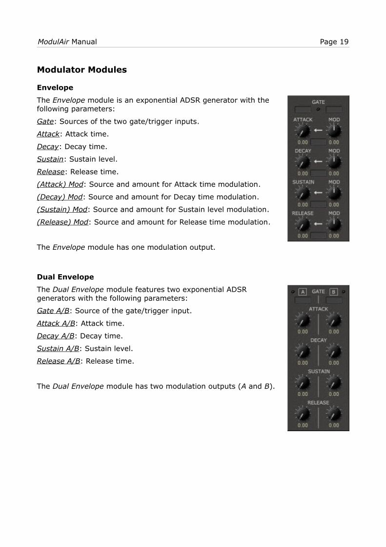
Envelope
The Envelope module is an exponential ADSR generator with thefollowing parameters:
Gate: Sources of the two gate/trigger inputs.
Attack: Attack time.
Decay: Decay time.
Sustain: Sustain level.
Release: Release time.
(Attack) Mod: Source and amount for Attack time modulation.
(Decay) Mod: Source and amount for Decay time modulation.
(Sustain) Mod: Source and amount for Sustain level modulation.
(Release) Mod: Source and amount for Release time modulation.
The Envelope module has one modulation output.
Dual Envelope
The Dual Envelope module features two exponential ADSRgenerators with the following parameters:
Gate A/B: Source of the gate/trigger input.
Attack A/B: Attack time.
Decay A/B: Decay time.
Sustain A/B: Sustain level.
Release A/B: Release time.
The Dual Envelope module has two modulation outputs (A and B).

ModulAir Manual Page 20
Quad Envelope
The Quad Envelope module features four exponential ADgenerators with the following parameters:
Gate A/B/C/D: Source of the gate/trigger input.
Attack A/B/C/D: Attack time.
Decay A/B/C/D: Decay time.
The Quad Envelope module has four modulation outputs (A to D).
Dual Linear Envelope
The Dual Linear Envelope module features two linear ADSRgenerators with the following parameters:
Gate A/B: Source of the gate/trigger input.
Attack A/B: Attack time.
Decay A/B: Decay time.
Sustain A/B: Sustain level.
Release A/B: Release time.
The Dual Linear Envelope module has two modulation outputs(A and B).
ModulAir Manual Page 21
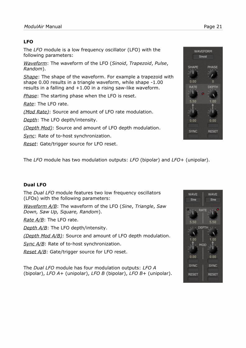
LFO
The LFO module is a low frequency oscillator (LFO) with thefollowing parameters:
Waveform: The waveform of the LFO (Sinoid, Trapezoid, Pulse, Random).
Shape: The shape of the waveform. For example a trapezoid withshape 0.00 results in a triangle waveform, while shape -1.00results in a falling and +1.00 in a rising saw-like waveform.
Phase: The starting phase when the LFO is reset.
Rate: The LFO rate.
(Mod Rate): Source and amount of LFO rate modulation.
Depth: The LFO depth/intensity.
(Depth Mod): Source and amount of LFO depth modulation.
Sync: Rate of to-host synchronization.
Reset: Gate/trigger source for LFO reset.
The LFO module has two modulation outputs: LFO (bipolar) and LFO+ (unipolar).
Dual LFO
The Dual LFO module features two low frequency oscillators(LFOs) with the following parameters:
Waveform A/B: The waveform of the LFO (Sine, Triangle, SawDown, Saw Up, Square, Random).
Rate A/B: The LFO rate.
Depth A/B: The LFO depth/intensity.
(Depth Mod A/B): Source and amount of LFO depth modulation.
Sync A/B: Rate of to-host synchronization.
Reset A/B: Gate/trigger source for LFO reset.
The Dual LFO module has four modulation outputs: LFO A (bipolar), LFO A+ (unipolar), LFO B (bipolar), LFO B+ (unipolar).

ModulAir Manual Page 22
Sample & Hold
The Sample & Hold module features two Sample & Hold units andan additional noise generator. It has the following parameters:
White: Level of the white noise.
Pink: Level of the pink noise.
Rate A/B: The Sample & Hold rate.
Trigger A/B: Trigger source for Sample & Hold (overrides Rate).
Input: The input source for Sample & Hold.
The Sample & Hold module has two audio outputs (White Noiseand Pink Noise) and two modulation outputs (A and B).

ModulAir Manual Page 23
Sequencer Modules
Sequencer
The Sequencer module is an eight-step analog-style sequencerwith the following parameters:
Clock: Trigger source for the sequencer clock.
Reset: Trigger source for the sequencer reset.
Link: Modulation source for sequencer link; when linking thesequencer with another sequencer module, the output of the othermodule should be added to the Link input.It works as follows: If the sequencer is in non-looping mode andhas finished the last sequence step, then the output of thesequencer will be determined by the Link input.
(Loop): Switches the sequencer from looping to non-looping.
Steps: The number of active sequencer steps.
Step 1–8: The value of the respective sequencer step.
The Sequencer module has one modulation output and twelvetrigger outputs: Clock, Clock Link (clocks only in non-looping mode when the sequencer has finished the last sequence step), Reset (clocks when the sequencer resets to step 1), Stop, Step 1–8 (clocks for each individual step).
Beat Sequencer
The Beat Sequencer module features four sixteen-step triggersequencers with the following parameters:
Clock: Trigger source for the sequencer clock.
Reset: Trigger source for the sequencer reset.
Div: Clock division factor.
(Loop): Switches the sequencer from looping to non-looping.
Steps: The number of active sequencer steps.
Step 1–16 A/B/C/D: The status (on/off) of the respectivesequencer step.
The Beat Sequencer module has nine trigger outputs: Clock, Clock Div, Clock Link (clocks only in non-looping mode when thesequencer has finished the last sequence step), Reset (clockswhen the sequencer resets to step 1), Stop, Line A–B (clocks forthe individual sequencer lines).

ModulAir Manual Page 24
Sequential Switch
The Sequential Switch module is an eight-step sequencer thatswitches between up to eight modulation inputs. It has thefollowing parameters:
Rate: The sequencer rate.
Clock: Trigger source for the sequencer clock (overrides Rate).
C.Div: Clock division factor.
Reset: Trigger source for the sequencer reset.
Link: Modulation source for sequencer link; when linking thesequencer with another sequencer module, the output of the othermodule should be added to the Link input.It works as follows: If the sequencer is in non-looping mode andhas finished the last sequence step, then the output of thesequencer will be determined by the Link input.
(Loop): Switches the sequencer from looping to non-looping.
Steps: The number of active sequencer steps.
In 1–8: The modulation source inputs of the respective step.
The Sequential Switch module has one modulation output and fourteen trigger outputs: Clock, Clock Div, Clock Link (clocks only in non-looping mode when the sequencer has finished the last sequence step), Reset (clocks when the sequencer resets to step 1), Stop, Step Active (clocks each time a step with active modulation input is reached), Step 1–8 (clocks for each individual step).
Audio Switch
The Audio Switch module is an eight-step sequencer that switchesbetween up to eight audio inputs. It is identical to the SequentialSwitch module with the difference that it switches audio signalsinstead of modulation signals.

ModulAir Manual Page 25
Effect Modules
BBD Delay
The BBD Delay module simulates a bucket brigade delay with thefollowing parameters:
Input A/B: Level and source of the input signal.
Time: Delay time.
(Time Range): Range of the delay time.
(Time) Mod: Source and amount for delay time modulation.
Freeze: Freezes the delay signal.
(Freeze Trigger): Trigger signals to freeze the delay signal.
Feedback: Feedback amount.
Mix: Mix between original and effect signal.
Quality: The quality of the effect signal.
The BBD Delay module has one audio outputs.
Dual Delay Line
The Dual Delay Line module features two delay lines with thefollowing parameters:
Input A/B: Level and source of the input signal.
Delay A/B: Delay time.
Clear A/B: Gate/trigger source for clearing the delay line.
Feed Forward: Feed forward coefficient of the delay line.
Feed Back: Feed back coefficient of the delay line.
Setting the Feed Forward coefficient to the exact negative value ofthe Feed Back coefficient will result in an Allpass filter delay.
The Dual Delay Line module has two audio outputs (A and B).

ModulAir Manual Page 26
Reverb
The Reverb module simulates a stereo reverb with the followingparameters:
Input A/B: Level and source of the input signal.
(Mono/Stereo): Switch from mono (A+B) to stereo input (A|B).
Predelay: Predelay time.
Size: Size of the reverberation room.
Damp: Damping of the reverb.
Length: Length of the reverb.
Spread: Stereo spread of the reverb signal.
Mix: Mix between original and effect signal.
The Reverb module has two audio outputs (Left and Right).
ModulAir Manual Page 27
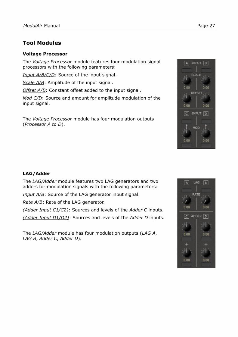
Tool Modules
Voltage Processor
The Voltage Processor module features four modulation signalprocessors with the following parameters:
Input A/B/C/D: Source of the input signal.
Scale A/B: Amplitude of the input signal.
Offset A/B: Constant offset added to the input signal.
Mod C/D: Source and amount for amplitude modulation of theinput signal.
The Voltage Processor module has four modulation outputs(Processor A to D).
LAG/Adder
The LAG/Adder module features two LAG generators and twoadders for modulation signals with the following parameters:
Input A/B: Source of the LAG generator input signal.
Rate A/B: Rate of the LAG generator.
(Adder Input C1/C2): Sources and levels of the Adder C inputs.
(Adder Input D1/D2): Sources and levels of the Adder D inputs.
The LAG/Adder module has four modulation outputs (LAG A, LAG B, Adder C, Adder D).

ModulAir Manual Page 28
Sample Delay
The Sample Delay module features six sample delays with thefollowing parameters:
Input A–F: Source of the input signal.
Delay A–F: Delay of the input signal (1 to 15 samples).
Since each module of ModulAir delays its input signal by onesample, the Sample Delay is useful for compensating the delaybetween different signal paths. For example if you mix two audiosignals A and B where B is routed through an extra module (e.g. afilter), the signal “phase” between A and B will differ by onesample. If you pass signal A through a Sample Delay, the resultingsignals will be “in sync” again.
The Sample Delay module has six audio outputs (Delay A to F).
Modulation Signal Delay/M2G
The Modulation Signal Delay/M2G module features a modulationsignal delay, a modulation signal adder and two Modulation–to–Gate converters. It has the following parameters:
(Delay) Input A/B: Source of the delay input signal.
Delay: Delay time.
Feedback: Feedback of the delay.
(Adder Input 1/2): Sources and levels of the adder inputs.
(M2G Input A/B): Source of the M2G input signal.
(M2G Threshold A/B): Threshold of the M2G. If the input signal ishigher than the threshold, the gate output of the M2G will beactive, else it will be inactive.
The Modulation Signal Delay/M2G module has two modulationoutputs (Delay, Adder) and two gate/trigger outputs (M2G A, M2G B).

ModulAir Manual Page 29
Gate Tools
The Gate Tools module features two gate modifiers, two triggerdividers and a gate/trigger signal join. It has the followingparameters:
(Modifier Input A/B): Source of the Modifier input signal.
Length A/B: Length of the modified gate signal.
(Length) Mod A/B : Source and amount for length modulation ofthe modified gate signal.
(Divide Input C/D): Source of the Divider input signal.
(Divisor C/D): Divisor of the Divider.
(Join Input 1–4): Source of the Join input signal.
The Gate Tools module has five gate/trigger outputs (Gate A, Gate B, Divider C, Divider D, Join E).

ModulAir Manual Page 30
Miscellaneous Functionality
Options Menu
When clicking on the Menu button, a context menu opens with the following options:
Copy Program Copy current program to internal clipboard
Paste Program Paste internal clipboard to current program
Load Program Load a program file containing a patch to ModulAir's current program
Save Program Save ModulAir's current program to a program file
Load Bank Load a bank file containing 64 ModulAir patches
Save Bank Save ModulAir’s 64 patches to a bank file
Init Program Initialize the current program
Check Online for Update
When connected to the Internet, this function will check if a newer version of ModulAir is available at fullbucket.de
Visit fullbucket.de Open fullbucket.de in your standard browser
MIDI Learn
Assigning MIDI controllers to ModulAir parameters is done via the MIDI Learn function. To activate MIDI Learn, click on the respective button and wiggle both the MIDI controller and ModulAir’s parameter that you want to link. If you want to unlearnthe assignment, right-click the MIDI Learn button (the label now reads “UNLEARN”) and activate it. Now wiggle the MIDI controller or the parameter that you want to unlearn.
Custom Tuning
For micro-tonal playing, you can load a TUN or SCL and KBM micro-tuning definition file by clicking on the Custom Tuning FILE button. Once you have loaded such a file you can switch micro-tuning on and off. For more information about micro-tuning check the Microtonal Synthesis website at http://www.microtonal-synthesis.com/ and Mark Henning’s website at https://www.mark-henning.de/.
MIDI CC Sources
16 MIDI controller signals can be used as modulation sources. To assign a MIDI CC to one of the 16 sources press the SET button and choose the respective controller. The same way works to unassign a controller.

ModulAir Manual Page 31
Frequently Asked Questions
How do I install ModulAir (Windows 32 bit version)?Just copy the files modulair.dll from the ZIP archive you have downloaded to your system's or favorite DAW's VST plug-in folder. Your DAW should automatically register the ModulAir VST plug-in the next time you start it.
How do I install ModulAir (Windows 64 bit version)?Just copy the file modulair64.dll from the ZIP archive you have downloaded to your system's or favorite DAW's VST plug-in folder. Your DAW should automatically register the ModulAir VST plug-in the next time you start it.
Note: You may have to remove any existing (32 bit) modulair.dll from your VST plug-in folder or else your DAW may screw the versions up...
How do I install ModulAir (Mac VST/AU universal 32/64 bit)?Locate the downloaded PKG package file modulair_1_0_0_mac.pkg in Finder (!) and do a right- or control-click on it. In the context menu, click on “Open”. You will be asked if you really want to install the package because it comes from an “unidentified developer” (me ). Click “OK” and follow the installation instructions.
What is the plug-in ID of the ModulAir?The ID is fbMD.
Will you support ModulAir?Yes. If you have problems, found a bug, or have some suggestions about ModulAir please send me a mail: [email protected] .
How do I know if a new version of ModulAir is available?When connected to the Internet, open the Options menu (see section Options Menu)by clicking the disk icon and select the entry “Check Online for Updates”. If a new version of ModulAir is available on fullbucket.de the respective information will be shown in a message box.
It crashes…!You have been warned: Introduction
I get no sound!Have you checked that a signal is connected to the overall output plugs in the Common Section?