modis level 1b in-granule calibration code (mod … level 1b in-granule calibration code (mod_pr02)...
TRANSCRIPT

MODIS Level 1B In-Granule Calibration Code (MOD_PR02) High-Level Design
Version 5.0.6 (PFM-Terra) Version 5.0.7 (FM1-Aqua)
SGS F C S B R
MCST Internal Memorandum # M1057
Prepared by
Members of the MODIS Characterization Support Team For
NASA/Goddard Space Flight Center Greenbelt, MD 20771
August 16, 2006
This document is released pending final approval and may be subject to further revision.

MCST L1B MODIS Level 1B Calibration Software High-Level Design Page ii Software Support Team MOD_PR02 V5.0.6 (TERRA)/V5.0.7 (AQUA) August 16, 2006
TABLE OF CONTENTS Section 1 Introduction _________________________________________________ 1
1.1 Identification and Scope 1
1.2 Purpose and Objectives 1
1.3 Document Organization 1
Section 2 Overview of Function, Operation and Architecture__________________ 2
2.1 Overview of Code Function and Processing Context 2
2.2 Code Input, Output and Ancillary Files 4 2.2.1 Files Needed and Typical File Sizes_____________________________ 4 2.2.2 Process Control File (PCF) ___________________________________ 10 2.2.3 Metadata Configuration File (MCF)____________________________ 12 2.2.4 Input Lookup Table Files ____________________________________ 13 2.2.5 MOD01 Input Granule ______________________________________ 13 2.2.6 MOD03 Input Granule ______________________________________ 13
2.3 Code Language and Library Usage 14
2.4 Code Compilation and Execution 14
2.5 General Architectural Design Considerations 15
Section 3 Top Level Code Design _______________________________________ 17
3.1 Short Descriptions of "main" and its Immediate Child Functions 17
3.2 Flow charts or PDL for "main" and Important Child Functions 21
Section 4 Code Function Tree __________________________________________ 31
Section 5 Miscellaneous Implementation Notes ____________________________ 33
5.1 Variance and Standard Deviation Formulas Used in Level 1B 33
5.2 Platform-Dependent Behavior In Math Functions 33
5.3 Presence of Band 26 SDSs and Implementation 34
5.4 Detector Order Conventions 35
5.5 Impact of Missing MOD01 Scan Data 36
5.6 Split Scans 36
Section 6 Acronyms __________________________________________________ 38
Section 7 References and Other Applicable Documents _____________________ 40
7.1 Libraries 40
7.2 File Specifications 40
MCST L1B MODIS Level 1B Calibration Software High-Level Design Page iii Software Support Team MOD_PR02 V5.0.6 (TERRA)/V5.0.7 (AQUA) August 16, 2006
7.3 Algorithm Documents 40
7.4 Other documents 42
7.5 Standards and Requirements 42
FIGURES Figure 2.1 Processing Context of the Level 1B code (MOD_PR02) 3 Figure 2.2 Illustration of principal input and output files for one execution of
MOD_PR02 4
TABLES Table 2.1 MOD_PR02 Input-Related Files 5 Table 2.2 Output generated by MOD_PR02 6 Table 2.3 Typical File Sizes of MOD_PR02 Input and Output Related Files 6 Table 2.4 Data Volume Breakdown in MOD01 granule 7 Table 2.5 Approximate Data Volume in 203-Scan L1B 250m EV product 7 Table 2.6 Approximate Data Volume in 203-Scan L1B 500m EV product 7 Table 2.7 Approximate Data Volume in 203-Scan L1B 1km EV product 8 Table 2.8 Approximate Data Volume in 203-Scan L1B On-Board Calibrator
product (MOD02OBC) 8 Table 2.9 Significant Process Control File (PCF) Logical Units Used by
MOD_PR02 11 Table 2.10 MOD_PR02 Source Files 16 Table 5.1 Summary of Detector Order Convention in Files related to
MOD_PR02 35

MCST L1B MODIS Level 1B Calibration Software High-Level Design Page 1 Software Support Team MOD_PR02 V5.0.6 (TERRA)/V5.0.7 (AQUA) August 16, 2006
1
Section 1 Introduction
1.1 Identification and Scope This document describes the high-level design of the Level 1B in-granule calibration code designated as MOD_PR02 which is used in the processing of MODIS data from both the Terra (PFM) and Aqua (FM1) platforms. The MODIS Characterization Support Team (MCST) is responsible for development of the Level 1B calibration algorithms and the implementation of those algorithms in MOD_PR02. MOD_PR02 is run by the NASA Goddard Space Flight Center MODIS Adaptive Processing System (MODAPS) and generates the calibrated Earth view products archived at ECS and available to users. Also run by MODAPS but not within the scope of this document is the Level 1B QA code, MOD_PR02QA, which copies metadata from the Earth view products to relatively small, ASCII file products. Other parts of the Level 1B calibration system, such as the cross-granule Solar diffuser processing code, are run at MCST and generate internal products used to support MCST data analysis, lookup table generation and validation. These other parts are also not included within the scope of this document. Separate platform-specific versions of the code exist for use (Version 5.0.6 for the Terra/PFM platform and Version 5.0.7 for the Aqua/FM1 platform), but the number of differences between the code versions is small. Differences between Terra and Aqua implementations, when they exist, are clearly marked in this document.
1.2 Purpose and Objectives The main objective of this document is to record high-level design information about the current architecture of MOD_PR02. Included are descriptions of the processing context of the code, code inputs and outputs and code execution.
1.3 Document Organization The major sections of the document are as follows:
Section 1 Introduction (this section) Section 2 Overview of the Function, Operation and Architecture Section 3 References and Other Applicable Documents Section 4 Top-Level Code Design Section 5 Code Function Tree Section 6 Miscellaneous implementation notes Section 7 Acronyms

MCST L1B MODIS Level 1B Calibration Software High-Level Design Page 2 Software Support Team MOD_PR02 V5.0.6 (TERRA)/V5.0.7 (AQUA) August 16, 2006
2
Section 2 Overview of Function, Operation and Architecture In this section we describe:
an overview of the code function and processing context, code input, output and ancillary files used, how the code is executed, the code language (C) and library usage, and general architectural design considerations.
2.1 Overview of Code Function and Processing Context Figure 2.1 illustrates the general flow of data products through MOD_PR02. The function of the Level 1A code (MOD_PR01) is to decommutate the telemetry packets in the binary Level 0 file, containing approximately 2 hours of raw MODIS data, into a set of Hierarchical Data Format (HDF) files, each containing 5 minutes of MODIS data. The geolocation code (MOD_PR03) calculates geolocation parameters, adds data to the intermediate L1A granule (producing the final L1A granule) and writes the geolocation granule. MOD_PR01 and MOD_PR03 are run together by MODAPS within PGE01. The function of MOD_PR02 is to apply calibration algorithms to the data in one L1A granule to produce three Earth view (EV) HDF product files and one on-board calibrator (OBC) HDF product file. Downstream Level 2 processes use the EV products. The OBC product is used by MCST to support analysis and generation of lookup tables (input parameters). The Level 1B QA code, MOD_PR02QA, copies ECS and other metadata from the 1km EV product into a separate ASCII file. MOD_PR02QA was derived from a similar code used by the LAND team, and will not be discussed further in this document. Not shown in Figure 2.1 is the fact that MOD_PR02 may use data from the leading and following (in time) L1A files. This is explained later in this document. The ASCII ".met" files generated along with each HDF file are also not shown. These ASCII metadata files contain a copy of the ECS core and archive metadata that are present in the associated HDF file. These metadata files are inserted into the ECS database.

MCST L1B MODIS Level 1B Calibration Software High-Level Design Page 3 Software Support Team MOD_PR02 V5.0.6 (TERRA)/V5.0.7 (AQUA) August 16, 2006
3
1km EV QA file (ASCII)
Intermediate L1A file (HDF)
Processing at Computer Resources of MCST (CROM)
Level 2 Processing
L1B LUT files
(or)
Level 1A code (MOD_PR01)
geolocation code (MOD_PR03)
L1A file (HDF)
Level 1B In-Granule Calibration code (MOD_PR02)
OBC file (HDF) 1km EV file (HDF) 500m EV file (HDF) 250m EV file (HDF)
Level 1B In-Granule QA code
(MOD_PR02QA)
L1B Cross Granule Special Product code
Solar Diffuser Special Product
L1B Solar Diffuser Analysis Code
L1B LUTs: m1, σm1
SRCA Special Product
L1B Cross Granule SRCA Calibration Preprocessor (Xgran_SRCA_Preproc)
Set of ASCII files (number and format depend on SRCA mode)
L1B Cross Granule SRCA Calibration code (Xgran_SRCA)
Processing by MODAPS
geolocationfile (HDF)
Level 0 file (binary)
MCST QA Database Software
PGE01
PGE02
Figure 2.1 Processing Context of the Level 1B code (MOD_PR02). Diagram does not
show that three consecutive L1A granules may be input to MOD_PR02 and that the cross-granule code may require several successive OBC files.

MCST L1B MODIS Level 1B Calibration Software High-Level Design Page 4 Software Support Team MOD_PR02 V5.0.6 (TERRA)/V5.0.7 (AQUA) August 16, 2006
4
2.2 Code Input, Output and Ancillary Files
2.2.1 Files Needed and Typical File Sizes Figure 2.2, below, summarizes the inputs and outputs for MOD_PR02 when run with Terra data. Inputs include three MOD01 granules, one MOD03 granule, three lookup table files and four metadata configuration files. The previous and following MOD01 granules are optional. Outputs include four product files, each accompanied by an associated metadata file. (Production of 500m and 250m resolution output files may be turned off for “night mode” data through the Process Control File or PCF. For details, see below.) For Aqua data processing, replace "MOD" with "MYD" on all input and output data, LUT files and MCF files. (For the remainder of this document, file names will be described in terms of the Terra file names.) Data from MOD_PR01 and MOD_PR03:
MOD01 file
(optional)
MOD01file
MOD03file
(previous 5 min. of MODIS data) (current 5 min. of MODIS data) (following 5 min. of MODIS data)
Level 1B Lookup Table Files: Metadata Configuration Files:
MOD02_Emissive_LUTs.hdf MOD02_Reflective_LUTs.hdf MOD02_QA_LUTs.hdf
MOD021KM.mcf MOD02HKM.mcf MOD02QKM.mcf MOD02OBC.mcf
MOD01 file
(optional)
MOD_PR02
Level 1B Output Products:
(1km product and metadata file)
(500m product and metadata file)
(250m product and metadata file)
(OBC product and metadata file)
MOD02OBC....hdf file MOD02OBC....met file
MOD02QKM....hdf file MOD02QKM....met file
MOD02HKM....hdf file MOD02HKM....met file
MOD021KM....hdf file MOD021KM....met file
Figure 2.2 Illustration of principal input and output files for one execution of MOD_PR02 on Terra data (for Aqua data processing, replace "MOD" with "MYD" for
all input data, output data, LUT, and MCF file names).
MCST L1B MODIS Level 1B Calibration Software High-Level Design Page 5 Software Support Team MOD_PR02 V5.0.6 (TERRA)/V5.0.7 (AQUA) August 16, 2006
5
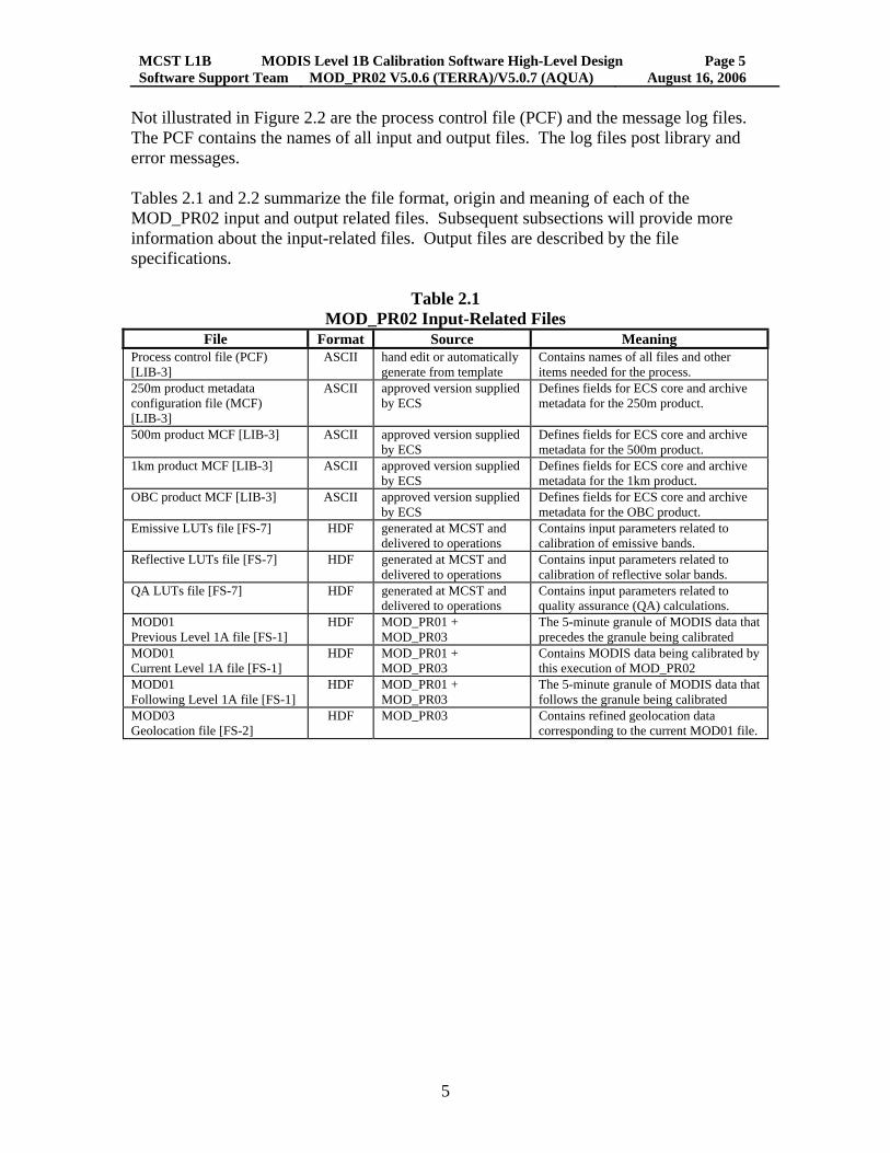
Not illustrated in Figure 2.2 are the process control file (PCF) and the message log files. The PCF contains the names of all input and output files. The log files post library and error messages. Tables 2.1 and 2.2 summarize the file format, origin and meaning of each of the MOD_PR02 input and output related files. Subsequent subsections will provide more information about the input-related files. Output files are described by the file specifications.
Table 2.1 MOD_PR02 Input-Related Files
File Format Source Meaning Process control file (PCF) [LIB-3]
ASCII hand edit or automatically generate from template
Contains names of all files and other items needed for the process.
250m product metadata configuration file (MCF) [LIB-3]
ASCII approved version supplied by ECS
Defines fields for ECS core and archive metadata for the 250m product.
500m product MCF [LIB-3] ASCII approved version supplied by ECS
Defines fields for ECS core and archive metadata for the 500m product.
1km product MCF [LIB-3] ASCII approved version supplied by ECS
Defines fields for ECS core and archive metadata for the 1km product.
OBC product MCF [LIB-3] ASCII approved version supplied by ECS
Defines fields for ECS core and archive metadata for the OBC product.
Emissive LUTs file [FS-7] HDF generated at MCST and delivered to operations
Contains input parameters related to calibration of emissive bands.
Reflective LUTs file [FS-7] HDF generated at MCST and delivered to operations
Contains input parameters related to calibration of reflective solar bands.
QA LUTs file [FS-7] HDF generated at MCST and delivered to operations
Contains input parameters related to quality assurance (QA) calculations.
MOD01 Previous Level 1A file [FS-1]
HDF MOD_PR01 + MOD_PR03
The 5-minute granule of MODIS data that precedes the granule being calibrated
MOD01 Current Level 1A file [FS-1]
HDF MOD_PR01 + MOD_PR03
Contains MODIS data being calibrated by this execution of MOD_PR02
MOD01 Following Level 1A file [FS-1]
HDF MOD_PR01 + MOD_PR03
The 5-minute granule of MODIS data that follows the granule being calibrated
MOD03 Geolocation file [FS-2]
HDF MOD_PR03 Contains refined geolocation data corresponding to the current MOD01 file.

MCST L1B MODIS Level 1B Calibration Software High-Level Design Page 6 Software Support Team MOD_PR02 V5.0.6 (TERRA)/V5.0.7 (AQUA) August 16, 2006
6
Table 2.2
Output generated by MOD_PR02 File Format Meaning
MOD02QKM 250m EV file [FS-3]
HDF Earth view calibrated product for 250m resolution bands.
MOD02HKM 500m EV file [FS-4]
HDF Earth view calibrated product for 500m resolution bands (includes 250m bands aggregated to appear at 500m resolution).
MOD021KM 1 km EV file [FS-5]
HDF Earth view calibrated product for 1 km resolution bands (includes 250m and 500m bands aggregated to appear at 1 km resolution).
MOD02OBC On-board-calibration (OBC) product [FS-6]
HDF Engineering telemetry and raw digital numbers for the blackbody (BB), space-view (SV), spectroradiometric calibration assembly (SRCA) and Solar diffuser (SD).
[250m EV file name].met ASCII Copy of ECS core and archive metadata from 250m HDF file. [500m EV file name].met ASCII Copy of ECS core and archive metadata from 500m HDF file. [1 km EV file name].met ASCII Copy of ECS core and archive metadata from 1 km HDF file. [OBC file name].met ASCII Copy of ECS core and archive metadata from OBC HDF file. LogReport, LogStatus, LogUser
ASCII Files that support the Status message facility (SMF). The LogStatus and LogReport files contain error messages written explicitly by the code (the same message is written to both files). Other messages (such as toolkit version and local time) are written to these files by the SDP toolkit.
Some of the MOD_PR02 input and output files are large in volume and have a significant impact on the design of the code. Table 2.3 displays typical file sizes for the types of files listed in Tables 2.1 and 2.2. When commanded to operate in "night-mode", the Terra and Aqua satellites only transmit MODIS Band 20 through 36 data. The mechanism causing this is discussed later in this section.
Table 2.3 Typical File Sizes of MOD_PR02 Input and Output Related Files
File or File Type
Format
Day mode (MB)
Night mode (MB) (if different)
Input-related Process control file (PCF) ASCII 0.03 Any product MCF ASCII 0.01 Emissive Lookup Tables file HDF 0.23 Reflective Lookup Tables file HDF 1.93 QA Lookup Tables file HDF 0.05 MOD01 (203-scan) HDF 574.14 189.76 MOD03 HDF 60.67 Output-related MOD02QKM HDF 286.05 22.19* MOD02HKM HDF 275.06 22.19* MOD021KM HDF 343.36 142.71 MOD02OBC HDF 58.94 Any ".met" file ASCII 0.02 Log files ASCII ** * Are not produced in night mode if production of high resolution data in night mode is
turned off. ** The file size of each "Log" file is very small assuming that the contents of previous
executions of MOD_PR02 are not retained. If the Log files are cumulative, they can grow to be quite large in size.
MCST L1B MODIS Level 1B Calibration Software High-Level Design Page 7 Software Support Team MOD_PR02 V5.0.6 (TERRA)/V5.0.7 (AQUA) August 16, 2006
7
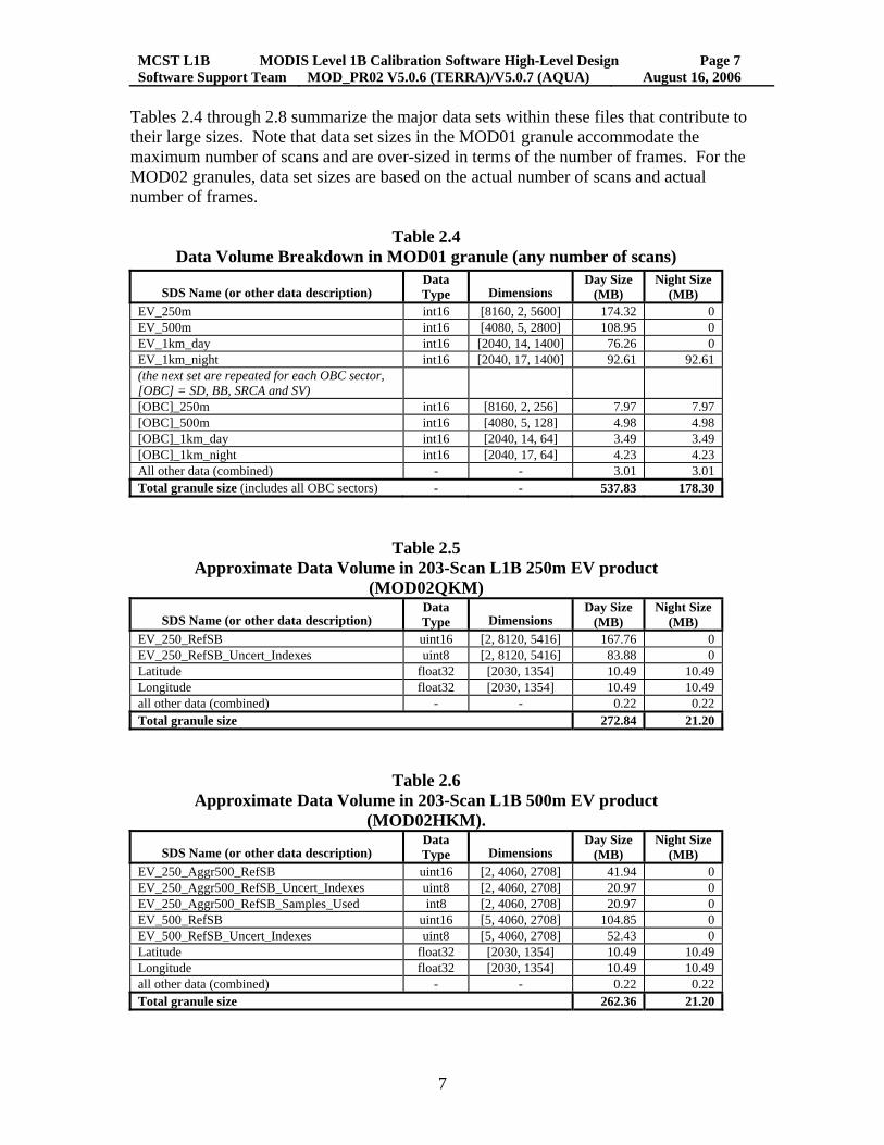
Tables 2.4 through 2.8 summarize the major data sets within these files that contribute to their large sizes. Note that data set sizes in the MOD01 granule accommodate the maximum number of scans and are over-sized in terms of the number of frames. For the MOD02 granules, data set sizes are based on the actual number of scans and actual number of frames.
Table 2.4 Data Volume Breakdown in MOD01 granule (any number of scans)
SDS Name (or other data description)
Data Type
Dimensions
Day Size (MB)
Night Size (MB)
EV_250m int16 [8160, 2, 5600] 174.32 0 EV_500m int16 [4080, 5, 2800] 108.95 0 EV_1km_day int16 [2040, 14, 1400] 76.26 0 EV_1km_night int16 [2040, 17, 1400] 92.61 92.61 (the next set are repeated for each OBC sector, [OBC] = SD, BB, SRCA and SV)
[OBC]_250m int16 [8160, 2, 256] 7.97 7.97 [OBC]_500m int16 [4080, 5, 128] 4.98 4.98 [OBC]_1km_day int16 [2040, 14, 64] 3.49 3.49 [OBC]_1km_night int16 [2040, 17, 64] 4.23 4.23 All other data (combined) - - 3.01 3.01 Total granule size (includes all OBC sectors) - - 537.83 178.30
Table 2.5 Approximate Data Volume in 203-Scan L1B 250m EV product
(MOD02QKM)
SDS Name (or other data description) Data Type
Dimensions
Day Size (MB)
Night Size (MB)
EV_250_RefSB uint16 [2, 8120, 5416] 167.76 0 EV_250_RefSB_Uncert_Indexes uint8 [2, 8120, 5416] 83.88 0 Latitude float32 [2030, 1354] 10.49 10.49 Longitude float32 [2030, 1354] 10.49 10.49 all other data (combined) - - 0.22 0.22 Total granule size 272.84 21.20
Table 2.6 Approximate Data Volume in 203-Scan L1B 500m EV product
(MOD02HKM).
SDS Name (or other data description) Data Type
Dimensions
Day Size (MB)
Night Size (MB)
EV_250_Aggr500_RefSB uint16 [2, 4060, 2708] 41.94 0 EV_250_Aggr500_RefSB_Uncert_Indexes uint8 [2, 4060, 2708] 20.97 0 EV_250_Aggr500_RefSB_Samples_Used int8 [2, 4060, 2708] 20.97 0 EV_500_RefSB uint16 [5, 4060, 2708] 104.85 0 EV_500_RefSB_Uncert_Indexes uint8 [5, 4060, 2708] 52.43 0 Latitude float32 [2030, 1354] 10.49 10.49 Longitude float32 [2030, 1354] 10.49 10.49 all other data (combined) - - 0.22 0.22 Total granule size 262.36 21.20
MCST L1B MODIS Level 1B Calibration Software High-Level Design Page 8 Software Support Team MOD_PR02 V5.0.6 (TERRA)/V5.0.7 (AQUA) August 16, 2006
8
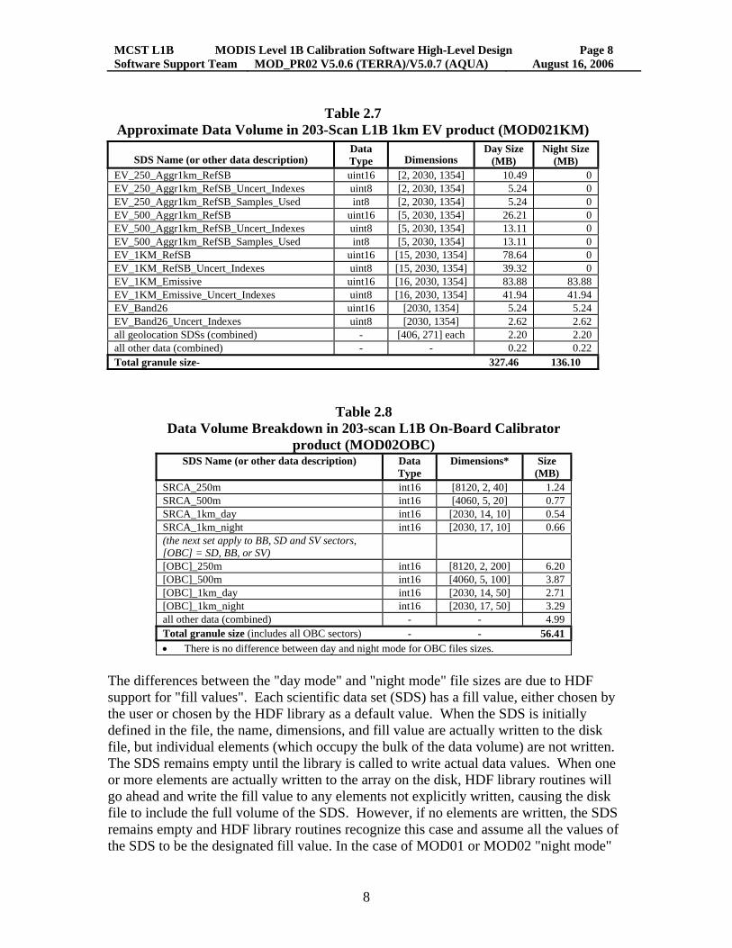
Table 2.7
Approximate Data Volume in 203-Scan L1B 1km EV product (MOD021KM)
SDS Name (or other data description) Data Type
Dimensions
Day Size (MB)
Night Size (MB)
EV_250_Aggr1km_RefSB uint16 [2, 2030, 1354] 10.49 0 EV_250_Aggr1km_RefSB_Uncert_Indexes uint8 [2, 2030, 1354] 5.24 0 EV_250_Aggr1km_RefSB_Samples_Used int8 [2, 2030, 1354] 5.24 0 EV_500_Aggr1km_RefSB uint16 [5, 2030, 1354] 26.21 0 EV_500_Aggr1km_RefSB_Uncert_Indexes uint8 [5, 2030, 1354] 13.11 0 EV_500_Aggr1km_RefSB_Samples_Used int8 [5, 2030, 1354] 13.11 0 EV_1KM_RefSB uint16 [15, 2030, 1354] 78.64 0 EV_1KM_RefSB_Uncert_Indexes uint8 [15, 2030, 1354] 39.32 0 EV_1KM_Emissive uint16 [16, 2030, 1354] 83.88 83.88 EV_1KM_Emissive_Uncert_Indexes uint8 [16, 2030, 1354] 41.94 41.94 EV_Band26 uint16 [2030, 1354] 5.24 5.24 EV_Band26_Uncert_Indexes uint8 [2030, 1354] 2.62 2.62 all geolocation SDSs (combined) - [406, 271] each 2.20 2.20 all other data (combined) - - 0.22 0.22 Total granule size- 327.46 136.10
Table 2.8 Data Volume Breakdown in 203-scan L1B On-Board Calibrator
product (MOD02OBC) SDS Name (or other data description) Data
Type Dimensions* Size
(MB) SRCA_250m int16 [8120, 2, 40] 1.24 SRCA_500m int16 [4060, 5, 20] 0.77 SRCA_1km_day int16 [2030, 14, 10] 0.54 SRCA_1km_night int16 [2030, 17, 10] 0.66 (the next set apply to BB, SD and SV sectors, [OBC] = SD, BB, or SV)
[OBC]_250m int16 [8120, 2, 200] 6.20 [OBC]_500m int16 [4060, 5, 100] 3.87 [OBC]_1km_day int16 [2030, 14, 50] 2.71 [OBC]_1km_night int16 [2030, 17, 50] 3.29 all other data (combined) - - 4.99 Total granule size (includes all OBC sectors) - - 56.41 • There is no difference between day and night mode for OBC files sizes.
The differences between the "day mode" and "night mode" file sizes are due to HDF support for "fill values". Each scientific data set (SDS) has a fill value, either chosen by the user or chosen by the HDF library as a default value. When the SDS is initially defined in the file, the name, dimensions, and fill value are actually written to the disk file, but individual elements (which occupy the bulk of the data volume) are not written. The SDS remains empty until the library is called to write actual data values. When one or more elements are actually written to the array on the disk, HDF library routines will go ahead and write the fill value to any elements not explicitly written, causing the disk file to include the full volume of the SDS. However, if no elements are written, the SDS remains empty and HDF library routines recognize this case and assume all the values of the SDS to be the designated fill value. In the case of MOD01 or MOD02 "night mode"

MCST L1B MODIS Level 1B Calibration Software High-Level Design Page 9 Software Support Team MOD_PR02 V5.0.6 (TERRA)/V5.0.7 (AQUA) August 16, 2006
9
SDSs, these SDSs are defined in the file for 250m and 500m resolution data but the arrays are never actually written. Hence, they occupy no significant disk space. The user also has the option to turn off production of “night mode” 250m and 500m resolution output files entirely, since no high resolution data are produced for “night mode” scans. See the discussion of the Process Control File (PCF) for specifics. The large volumes in the Earth view data sets in the MOD01 input granules and the MOD02 output granules make it impractical to hold these data sets entirely in memory (either reading in the data sets or writing out the data sets). Thus, MOD_PR02 is designed to loop through scans, accomplishing the processing one scan at a time. HDF library calls are used to read subsets of data from the MOD01 granule and write the corresponding subsets of data to the MOD02 output granules. In this way, the actual memory requirements for the code are greatly reduced from a design where an entire data set is held in memory. For both MODIS instruments, the algorithms that involve averaging of data over scan utilize data from either the OBC sectors or engineering telemetries (specifically, temperatures). Thus, these averaging-over-scan calculations can be done in memory.
MCST L1B MODIS Level 1B Calibration Software High-Level Design Page 10 Software Support Team MOD_PR02 V5.0.6 (TERRA)/V5.0.7 (AQUA) August 16, 2006
10
2.2.2 Process Control File (PCF) The process control file [Appendix C in LIB-3] is the single most important "input" file to MOD_PR02. It contains the names of all other input and output files. The name of the PCF is supplied to the SDP Toolkit library by a UNIX environment variable. SDP toolkit library [LIB-3] functions are used to read data from the PCF. The format of the PCF comes from a template supplied by ECS in each new SDP toolkit version. Developers add information to the format (as described below) but may not remove items. Appendix C in reference [LIB-3] and Appendix H of [STD-2] provide examples of the PCF. The directory locations and file names of all other input files, the four HDF output files and the three log files must be placed into the PCF file. In addition to the physical file names, the MOD01 input granules, MOD03 input granule and the lookup table (LUT) input files also need universal reference (UR) names entered in the PCF file. These URs are placed in the ECS core metadata (InputPointer and AncillaryInputPointer fields). Within the ECS database, the URs provide the means to trace back to the individual input granules. The information for each file is placed on one line of the PCF, which begins with a logical identifier number. Developers cannot arbitrarily change the logical identifiers, even if the code will work on the development platform. When new information is added to the PCF, SDST is the single point of contact with ECS for defining the actual values of the new logical identifiers.

MCST L1B MODIS Level 1B Calibration Software High-Level Design Page 11 Software Support Team MOD_PR02 V5.0.6 (TERRA)/V5.0.7 (AQUA) August 16, 2006
11
Table 2.9
Significant Process Control File (PCF) Logical Units Used by MOD_PR02
Input Data Files Logical Unit # Example Remarks
500000 MOD01.A2002176.0625.003.2002176200522.hdf |/L1A | |UR_MOD01.A2002176.0625.003.2002176200522.hdf |MOD01.A2002176.0625.003.2002176200522.hdf |1
Optional Leading L1A Input Granule
500001 MOD01.A2002176.0630.003.2002176200906.hdf |/L1A | |UR_MOD01.A2002176.0630.003.2002176200906.hdf |MOD01.A2002176.0630.003.2002176200906.hdf |1
L1A Input Granule
500002 MOD01.A2002176.0635.003.2002176201226.hdf |/L1A | |UR_MOD01.A2002176.0635.003.2002176201226.hdf |MOD01.A2002176.0635.003.2002176201226.hdf |1
Optional Trailing L1A Input Granule
600000 MOD03.A2002176.0625.003.2002176200522.hdf |/L1AGEO | |UR_MOD03.A2002176.0625.003.2002176200522.hdf |MOD03.A2002176.0625.003.2002176200522.hdf |1
L1A Geolocation Input Granule
Static Input files
Logical Unit # Example Remarks 700050 MOD02_Reflective_LUTs.hdf |/SRCA/MOD_PR02_TERRA |
|UR_MOD02_Reflective_LUTs.hdf | |1 Reflective Lookup Tables File
700060 MOD02_Emissive_LUTs.hdf |/SRCA/MOD_PR02_TERRA | |UR_MOD02_Emissive_LUTs.hdf | |1
Emissive Lookup Tables File
700070 MOD02_QA_LUTs.hdf |/SRCA/MOD_PR02_TERRA | |UR_MOD02_QA_LUTs.hdf | |1
Quality Assurance Lookup Tables File
700250 MOD02QKM.mcf |/SRCA/MOD_PR02_TERRA | | | |1 250m resolution output metadata configuration file (MCF)
700251 MOD02HKM.mcf |/SRCA/MOD_PR02_TERRA | | | |1 500m resolution output MCF 700252 MOD021KM.mcf |/SRCA/MOD_PR02_TERRA | | | |1 1km resolution output MCF 700253 MOD02OBC.mcf |/SRCA/MOD_PR02_TERRA | | | |1 On-board calibration data MCF
Output Files
Logical Unit # Example Remarks 700000 MOD02QKM.2002176.0630.4.1.1x.hdf |/V4.1.1x |
|UR_MOD02QKM.2002176.0630.4.1.1x.hdf |MOD02QKM.2002176.0630.4.1.1x.hdf |1
250m resolution output file
700001 MOD02HKM.2002176.0630.4.1.1x.hdf |/V4.1.1x | |UR_MOD02HKM.2002176.0630.4.1.1x.hdf |MOD02HKM.2002176.0630.4.1.1x.hdf |1
500m resolution output file
700002 MOD021KM.2002176.0630.4.1.1x.hdf |/V4.1.1x | |UR_MOD021KM.2002176.0630.4.1.1x.hdf |MOD021KM.2002176.0630.4.1.1x.hdf |1
1km resolution output file
700010 MOD02OBC.2002176.0630.4.1.1x.hdf |/V4.1.1x | |UR_MOD02OBC.2002176.0630.4.1.1x.hdf |MOD02OBC.2002176.0630.4.1.1x.hdf |1
On-board calibration output file
Other LUNs
Logical Unit #
Name Example Remarks
800510 Satellite AM1M AM1M=Terra, PM1M=Aqua 800600 ReprocessingPlanned further update is
anticipated Set by MCST management
800605 ReprocessingActual processed once Set by MCST management 800610 MCSTLUTVersion 3.1.0.1_Terra T he MCST Version number, which is checked against
the LUT version number in the LUT HDF files. 800615 Write_Night_Mode_HiRes_Data 0 This parameter determines whether the 250m and 500m
data sets are created when all scans in a granule are NIGHT mode. 1 = Create night mode High Resolution data; 0 = Creation disabled. Typically set to 0 in production processing.
800620 ProcessingCenter GSFC Set by data processing location.

MCST L1B MODIS Level 1B Calibration Software High-Level Design Page 12 Software Support Team MOD_PR02 V5.0.6 (TERRA)/V5.0.7 (AQUA) August 16, 2006
12
2.2.3 Metadata Configuration File (MCF) The metadata configuration file (MCF) is an ASCII file with an easily identifiable format. There is one MCF for each output product of MOD_PR02. Each MCF identifies all mandatory and optional fields in the ECS core and archive metadata for the associated product. The difference between core and archive metadata is that the fields of the core metadata are (in principle) searchable by users through the LADS web site. Archive metadata are not searchable. Each field in either core or archive metadata is registered in the ECS data base and developers cannot arbitrarily add or delete fields or the product will be rejected (it will not insert into the data base). SDST is the point of contact for adding or deleting fields from either core or archive metadata. Because of the need to promote stability in the ECS system, additions or deletions to the metadata will be made only infrequently. If additions or deletions from the metadata are required, the developer can hand-edit the MCF for testing purposes. However, ultimately, all changes have to be approved by ECS. When approved, ECS will deliver (to SDST) new MCFs to be used with the code. The developer should then re-test the code with these official MCFs and deliver these with the code for any future code deliveries. In the MCF, the "Data Location" identifies who is responsible for supplying the data to the core or archive metadata. For the developers of MOD_PR02, those fields with Data Location = "PGE" must be explicitly assigned within the code. Any field that has Mandatory = "True" in the MCF must appear in the product or it will not insert into the ECS database when run in MODAPS. Fields with Mandatory = "False" may be optionally assigned. The MCF is read within the call to the SDP toolkit function PGS_MET_Init (where the appropriate logical identifier is passed into the function). When this occurs, any value that is defined in the MCF (has a "Value = ..." included) becomes initialized and will be written to the product metadata without any explicit code statements. Examples of this feature in MOD_PR02, are the ECS core metadata fields "ShortName" and "VersionID". The SDP toolkit functions treat the ECS core metadata as one block of text containing textual representations of all field values. Similarly, the archive metadata is treated as one block of text. When metadata are determined within the code itself, they must be placed in strings and then "inserted" into the core or archive metadata using calls to SDP toolkit functions. When the ECS core and archive metadata appear in the HDF product files, they each are implemented as one file attribute (of type char8), where all field values of the appropriate metadata are lumped together in the attribute. In addition to [LIB-3], see the SDST MODIS Science Computing Facility Software Delivery Guide [STD-2] for more information about ECS metadata in the MODIS products and the toolkit functions used. This document contains formats for some of the metadata values, such as the LocalGranuleID (naming convention for the product files).

MCST L1B MODIS Level 1B Calibration Software High-Level Design Page 13 Software Support Team MOD_PR02 V5.0.6 (TERRA)/V5.0.7 (AQUA) August 16, 2006
13
2.2.4 Input Lookup Table Files The MOD_PR02 lookup table (LUT) files contain input parameters that affect the calibration algorithms or affect values that are written to the output products. The three lookup table files are standard HDF-4 files and are described in reference [FS-7]. The information that defines each LUT is placed in the MOD_PR02 source files: L1B_Tables.c and .h. The LUT files are generated by MCST using the utility program "generate_luts", which also links to certain MOD_PR02 source files.
2.2.5 MOD01 Input Granule Normally, there are three MOD01 input granules defined in the PCF file for MOD_PR02. These three granules represent successive 5-minute chunks of MODIS data. A MOD_PR02 execution has the purpose of calibrating the raw data input from the "middle" or "current" MOD01 granule. The reason that the previous and following granules are supplied as input to MOD_PR02 is that the emissive bands calibration algorithm refreshes the linear calibration coefficients on each scan through a moving average of OBC blackbody measurements. Data from the previous and following granules, if available, are used to supply the full baseline in calculating these averages. MOD_PR02 checks the data collection times of the previous and following granules against the collection time of the input granule. If the previous/following granule does not have a collection time immediately preceding/following (respectively) that of the input granule, it is treated as a missing granule and not used for emissive calibration. If there are up to 5 scans dropped between the previous/following granule and the middle granule, the previous/following granule may still be used for emissive calibration.
2.2.6 MOD03 Input Granule The main purpose of ingesting the MOD03 granule that coincides with the current MOD01 granule is to supply subsets of geolocation information to the MOD_PR02 output files. Additionally, two algorithms in MOD_PR02 utilize information from the MOD03 granule:
Determining if the moon is in the space-view port (uses the Moon Vector) Determining if day mode bands are telemetered at night (uses SD Sun azimuth
and zenith) The only consistency checks that are made in MOD_PR02 between the input MOD03 granule and the current MOD01 granule are that the number of scans must be the same in each and that the satellite must be the same. Thus, for some local testing purposes, the MOD_PR02 developer can use any geolocation file that has the correct number of scans

MCST L1B MODIS Level 1B Calibration Software High-Level Design Page 14 Software Support Team MOD_PR02 V5.0.6 (TERRA)/V5.0.7 (AQUA) August 16, 2006
14
and the correct satellite platform. For generation of delivery comparison files, however, the geolocation file must match the current MOD01 file.
2.3 Code Language and Library Usage The MOD_PR02 code is written in ANSI C and uses the HDF [LIB-1], HDF-EOS [LIB-2] and the SDP Toolkit [LIB-3] libraries. The developer cannot use the full complement of the C language and must conform to certain in-code documentation standards specified by ECS. In general, all file access (opening, closing, reading, and writing) must be accomplished using calls to the three libraries defined above. The developer cannot use the standard I/O C library (stdio.h). The MODIS Software Development Standards and Guidelines document [STD-1] describes the proper format for prologs to functions and include files, prohibited functions and other general restrictions. Additionally, prohibited functions cannot be made legal by putting them inside preprocessor statements [STD-3]. Although not prohibited, the use of "malloc" to dynamically allocate memory in-line has been discouraged by SDST to maximize robustness when running in the ECS operations environment. Consequently, "malloc" is rarely used in MOD_PR02 and is not used for any substantial memory allocation. Rather, all variables requiring appreciable random access memory are created using explicitly defined arrays -- either individually or as structure members. These arrays become allocated as automatic variables when functions are invoked. According to SDST staff, when a UNIX process requests more memory through automatic-variable allocation, the process will automatically go into a "wait" mode if the memory is not immediately available. When memory becomes available, then the process can latch onto the memory and continue running. On the other hand, if memory is not available when malloc is invoked, the code developer must either:
terminate the code with an "out of memory" error message, or write additional code, which accomplishes the "waiting" function, thereby
attempting the re-allocation at a later time. The problem with simply killing a major process like MOD_PR02 in a production environment is that the following-on processes which need the outputs of the process that is killed will also die. Consequently, processing halts and the restart of the chain of processes may be difficult.
2.4 Code Compilation and Execution In order to compile and execute MOD_PR02, various environment variables need to be defined (these are related to the HDF, HDF-EOS and SDP libraries). Within a UNIX "C" shell (csh), the user needs to "source" two files which contain these environment variables (NOTE: path names may be machine dependent):
MCST L1B MODIS Level 1B Calibration Software High-Level Design Page 15 Software Support Team MOD_PR02 V5.0.6 (TERRA)/V5.0.7 (AQUA) August 16, 2006
15
source /usr/local/SDPTK/TOOLKIT/bin/dec/pgs-dev-env.csh source /usr/local/SDPTK/TOOLKIT/hdfeos/bin/dec/hdfeos_env.csh
Examples of the compilation-related environment variables that become defined are: CC -- defines the platform C compiler CFLAGS -- defines compilation flags for the platform HDFINC -- defines location of HDF include files HDFLIB -- defines location of HDF libraries There are also environment variables for the HDF-EOS and SDP Toolkit libraries. The compilation-related environment variables are used within the makefile that accompanies the source code. Prior to executing the code, the user must develop a process control file (PCF), as described earlier in this section. The name of the PCF is supplied to the code through the environment variable “PGS_PC_INFO_FILE”. Names of all other files are contained in the PCF. After creating the PCF and defining the PGS_PC_INFO_FILE environment variable, the user simply enters the name of the code executable on the command line to actually execute the code. Within MCST, MOD_PR02 has been successfully compiled and executed on SGI, Linux, and DEC ALPHA machines. Execution times on a single processor are on the order of 15 to 20 minutes of CPU (20 to 30 minutes of clock time because of intensive I/O operations). RAM requirements are on the order of 70 MB. If a fatal error occurs when executing MOD_PR02, any files that have been generated should be discarded. This is due to the fact that open HDF accesses and files are not closed in a fatal error termination. Thus, files that may have been created could appear to be empty or defective and may occupy a large volume on the disk.
2.5 General Architectural Design Considerations MOD_PR02 is designed and coded as a top-down, sequential processing code. There are no substantial object-oriented design features. The MOD_PR02 code is organized into modules that roughly subdivide the functional requirements of the calibration process. Table 2.10 summarizes the source files in terms of the intended functionality.

MCST L1B MODIS Level 1B Calibration Software High-Level Design Page 16 Software Support Team MOD_PR02 V5.0.6 (TERRA)/V5.0.7 (AQUA) August 16, 2006
16
Table 2.10
MOD_PR02 Source Files Module Purpose
L1B.c Contains "main", controls overall flow in the code. L1B_Tables.c L1B_Tables.h
Read all lookup tables into arrays held in memory.
Preprocess.c Preprocess.h PreprocessP.h
Opens the MOD01 middle granule (for duration of code) and reads essential data. Accomplish pre-calibration calculations for emissive and or reflective processing; write the bulk of the OBC file.
L1B_Setup.c L1B_Setup.h L1B_SetupP.h
Open output EV granules, set up HDF-EOS swaths, calculate some metadata, and initialize arrays used in calculating some QA statistics.
Emissive_Cal.c Emissive_Cal.h
Calibrate one scan of EV pixels for thermal emissive bands
Reflective_Cal.c Reflective_Cal.h Reflective_CalP.h
Calibrate one scan of EV pixels for reflective solar bands. Includes applying SWIR out of band correction for SWIR bands (5, 6, 7, 26).
Granule.c Granule.h GranuleP.h
Contains functions to read a scan of MOD01 EV sector data, write a scan of MOD02 science data to output granules, post error message, close granules
Metadata.c Metadata.h MetadataP.h
Accomplish granule-level metadata calculations. Write the ECS core and archive metadata
HDF_Lib.c HDF_Lib.h
General purpose functions for reading and writing HDF-4 objects.
Fnames.h Define Logical Identifier Numbers (logical identifiers) used in the PCF PGS_Error_Codes.h PGS_MODIS_36100.h
Define macros for error codes that are used with the PGS error reporting system.
The header files named "[module_name].h" contain macros and other declarations that are used in other modules. The header files named "[module_name]P.h" contain macros and declarations that are used only in the file "[module_name].c". This organization helps to separate out those data that are used only within a given module. Despite the seemingly logical organization indicated above, there is a significant amount of intertwining of the modules. For example, input and output files are often opened in one part of the code and closed in a different, unrelated part of the code. Thus, changes to MOD_PR02 generally need to be designed by looking globally throughout the code. Ramifications of a change in one part of the code to other parts of the code must always be thoroughly examined.

MCST L1B MODIS Level 1B Calibration Software High-Level Design Page 17 Software Support Team MOD_PR02 V5.0.6 (TERRA)/V5.0.7 (AQUA) August 16, 2006
17
Section 3 Top Level Code Design This section will describe details of the design for a few of the top-level MOD_PR02 functions. Specifically, "main" and its immediate child functions are described: main
Open_and_Read_L1A Read_L1B_Tables Determine_Other_Missing_Scans Preprocess_L1A_Data L1B_Setup Read_L1A_EV_Scan Emissive_Cal Reflective_Cal Aggregate_L1B Band_26_Crosstalk_Correction Copy_Band_26_Data Fill_Dead_Detector_SI Write_L1B_EV_Scan Write_L1B_ScanMeta Gran_Meta_Cal Write_Gran_Metadata Close_L1A_Granule Close_L1B_Granule
The next subsection will give brief descriptions of each of the above. Following that subsection, flow charts or program design language (PDL) are provided for some of the above.
3.1 Short Descriptions of "main" and its Immediate Child Functions main Controls the entire flow of calculations within MOD_PR02. Open_and_Read_L1A This function opens the L1A granule to be processed and reads in data for all members of the L1A_granule_t structure. The file remains open (both SD and Vdata) upon function exit. Read_L1B_Tables Read all lookup tables (LUTs) into arrays held in memory. These include emissive, reflective and QA LUTs. In a few cases, additional values are calculated from the LUT values read and assigned to arrays for later processing.

MCST L1B MODIS Level 1B Calibration Software High-Level Design Page 18 Software Support Team MOD_PR02 V5.0.6 (TERRA)/V5.0.7 (AQUA) August 16, 2006
18
Determine_Other_Missing_Scans This function examines validity of certain L1A data and, based on options defined in the LUTs, determines additional scans to be treated as completely missing (meaning that data will not be calibrated for any band of the scan). Preprocess_L1A_Data This routine performs a number of functions:
Calculates the Response vs. Scan Angle (RVS) correction parameters for use in both emissive and reflective calibration.
Reads OBC and engineering data from the MOD01 files Computes emissive band parameters with a sliding average over scan
(necessitating the use of the previous and following MOD01 granules, if available).
Computes temperature quantities in engineering units Calculates frame averaged SV counts and standard deviation with outlier rejection
for all bands Writes the bulk of the OBC file (ECS and other metadata are added later). The
OBC file is created within this function and closed upon exit. Other functions will re-open the OBC file to add additional data.
Opens, reads calibration information from, and closes the previous and following MOD01 granules (if present).
L1B_Setup This routine performs a variety of functions in preparation for EV calibration:
Opens SDS access to each of the four MOD01 file EV SDSs (which remain open after function exit)
Calculates radiance and reflectance coefficients used in Reflective_Cal Sets the radiance, reflectance and emissive scales and offsets for the L1B data
products Creates HDFEOS Swaths and data fields for each MOD_PR02 output file (file
pointers remain open after function exit) Creates band-subsetting SDSs Opens SDS access for each of the EV SDSs in the MOD_PR02 EV files and
create attributes for all (accesses remain open after function exit) Reads subsampled SDSs from geolocation file and writes those data and their
attributes into the 1km file Assigns nadir-frame latitude and longitude to members of L1B_Scan_Meta to be
written later in Write_L1B_ScanMeta Assigns members of the L1B_Scan_Meta to be written to the L1B EV files later
in Write_L1B_ScanMeta Initializes the QA values of total number of pixels, number of valid pixels,
number of saturated pixels, number of missing pixels, pixels representing negative values below noise, and pixels for which Emissive calibration coefficients cannot be computed.

MCST L1B MODIS Level 1B Calibration Software High-Level Design Page 19 Software Support Team MOD_PR02 V5.0.6 (TERRA)/V5.0.7 (AQUA) August 16, 2006
19
Read_L1A_EV_Scan For the input scan index, S, corresponding to a "Day" mode, this routine reads Earth view (EV) data from the current MOD01 granule for that scan from each of the four L1A EV SDSs: EV_250m, EV_500m, EV_1km_day, EV_1km_night. If the scan is not a "Day" mode scan, then only the data from the EV_1km_night SDS is read. Emissive_Cal This routine accomplishes the calibration of one scan of EV pixels for Emissive bands. Corrections to the digital numbers are applied for electronic background and for the angular dependence of the response of the scan mirror (RVS). For the MODIS/Terra instrument (PFM), correction may also be applied for cross-talk for PC bands (the leak from band 31 to band 32, 33, 34, 35, and 36) depending on the switch value in the lookup table. The radiance is computed after the corrections. If the radiance can be computed and is in a valid range, it is converted to a scaled integer in the range of [0-32767]. If a valid value cannot be computed, the scaled integer is set to a value in the range of [32768-65535]. Specific values in the range of [32768-65535] are used to denote why a valid value could not be obtained (a list of these is in the L1B file specifications). This routine also computes the uncertainty in the radiance product for every pixel, and converts the uncertainty to a 4-bit uncertainty index, stored in the 4 least significant bits of an 8-bit unsigned integer. Computed values for this scan are stored in memory and are written to the L1B product files in the function Write_L1B_EV_Scan. Reflective_Cal This routine accomplishes the calibration of one scan of EV pixels for Reflective Solar Bands. Raw digital signals, DN, are corrected for known instrumental effects to produce corrected digital signals, dn* for every scan, frame, subframe, band and detector. Corrections are applied for the effect of instrument and focal plane temperature on detector responsivity, for the electronic background, for the angular dependence of the response of the scan mirror, for non-linearities in the Analog to Digital Converters, and for the effect of an out-of-band spectral leak in the SWIR bands 5, 6 and 7. Detectors within each spectral band are placed on a common scale by scaling dn* by relative calibration coefficients of the detectors in each band, to produce dn**. Each final dn** value, if valid, is scaled to an integer in the range of [0-32767] and placed in an unsigned, 16-bit integer variable (which has a full range of [0-65535]). If a valid value cannot be computed, the scaled integer is set to a value in the range of [32768-65535]. Specific values in the range of [32768-65535] are used to denote why a valid value could not be obtained (a list of these is in the L1B file specifications). This routine also computes the uncertainty in the reflectance product for every pixel, and converts the uncertainty to a 4-bit uncertainty index, stored in the 4 least significant bits of an 8-bit unsigned integer. Computed values for this scan are stored in memory and are written to the L1B product files in the function Write_L1B_EV_Scan. Aggregate_L1B For one "Day" mode scan of calibrated Earth view data, this routine performs spatial integration (or aggregation) of each of the higher resolution bands (250m or 500m) to the lower resolution appropriate for the 500m or 1km L1B granule products. In addition to

MCST L1B MODIS Level 1B Calibration Software High-Level Design Page 20 Software Support Team MOD_PR02 V5.0.6 (TERRA)/V5.0.7 (AQUA) August 16, 2006
20
aggregating the scaled integer and uncertainty index values, the number of samples used in the aggregation is saved for later writing to the L1B products. Computed values for this scan are stored in memory and are written to the L1B product files in the function Write_L1B_EV_Scan. Band_26_Crosstalk_Correction This function corrects Band 26 data. For one “Day” mode scan of calibrated Earth view data, a crosstalk correction is applied to the Band 26 data using the values of the aggregated Band 5 scaled integers and correction terms derived from a lookup table. Copy_Band_26_Data This function copies band 26 data from the EV_1km_RefSB structure member of L1B_Scan to the appropriate Band_26 structure member. The values are written to the 1km product file in function Write_L1B_EV_Scan. (See the implementation note on Band 26 SDS in Section 6) Fill_Dead_Detector_SI This function fills in reasonable pixel values in one Level 1B EV product file SDS for pixels that correspond to dead detectors. Values from adjacent (live) detectors are used to determine the values to assign to the dead-detector pixels. If possible, a linear average from adjacent pixels is calculated. This operation is applied only to the native resolution L1B data sets, not aggregated data sets. Write_L1B_EV_Scan This routine writes one scan of L1B EV data, including scaled integers, uncertainty indices and samples used, as appropriate. For a day-mode scan, all resolutions are written. For a night mode scan, only data for the emissive bands and for the band 26 SDS are written. Write_L1B_ScanMeta This routine writes Level 1B scan metadata into the three Earth view (EV) L1B product files. The Level 1B scan metadata are implemented in the lone Vdata "Level 1B Swath Metadata" in the EV files. This routine also writes the "Bit QA Flags" into OBC file as an SDS. The OBC file is re-opened and subsequently closed for this operation. Gran_Meta_Cal This routine computes various statistics such as percent of missing data that are written to the MOD_PR02 product files. Also, many values previously calculated are copied from different structures into the L1B_Gran_Meta structure. Write_Gran_Metadata This function writes many individual HDF file attributes of metadata to the MOD_PR02 output products and also writes the ECS core and archive metadata. Many of the values for the ECS metadata are copied from in the current MOD01 granule within this function. Some values come from previous calculations within MOD_PR02.
MCST L1B MODIS Level 1B Calibration Software High-Level Design Page 21 Software Support Team MOD_PR02 V5.0.6 (TERRA)/V5.0.7 (AQUA) August 16, 2006
21
Close_L1A_Granule This routine ends access to all L1A SDSs and ends the SD and Vdata interfaces to the current MOD01 granule file, closing the file. Close_L1B_Granule This routine ends SDS access to all open MOD02 EV SDSs and ends swath interface to all MOD02 EV granule files.
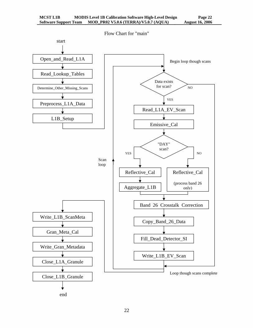
3.2 Flow charts or PDL for "main" and Important Child Functions The following pages contain flow charts or PDL for "main" and some of the immediate child functions of "main". The function tree in the next section indicates the full scope of MOD_PR02 functions.
MCST L1B MODIS Level 1B Calibration Software High-Level Design Page 22 Software Support Team MOD_PR02 V5.0.6 (TERRA)/V5.0.7 (AQUA) August 16, 2006
22
Flow Chart for "main" start
Begin loop though scans
YES
NO YES
Scanloop
Read_Lookup_Tables
Determine_Other_Missing_Scans
L1B_Setup
Read_L1A_EV_Scan
Emissive_Cal
Reflective_Cal
"DAY" scan?
Aggregate_L1B
Write_L1B_EV_Scan
Gran_Meta_Cal
Write_Gran_Metadata
Close_L1A_Granule
Close_L1B_Granule
Write_L1B_ScanMeta Copy_Band_26_Data
NO
Data exists for scan?
Reflective_Cal
(process band 26 only)
Band 26 Crosstalk Correction
Open_and_Read_L1A
Preprocess_L1A_Data
Fill_Dead_Detector_SI
Loop though scans complete
end
MCST L1B MODIS Level 1B Calibration Software High-Level Design Page 23 Software Support Team MOD_PR02 V5.0.6 (TERRA)/V5.0.7 (AQUA) August 16, 2006
23
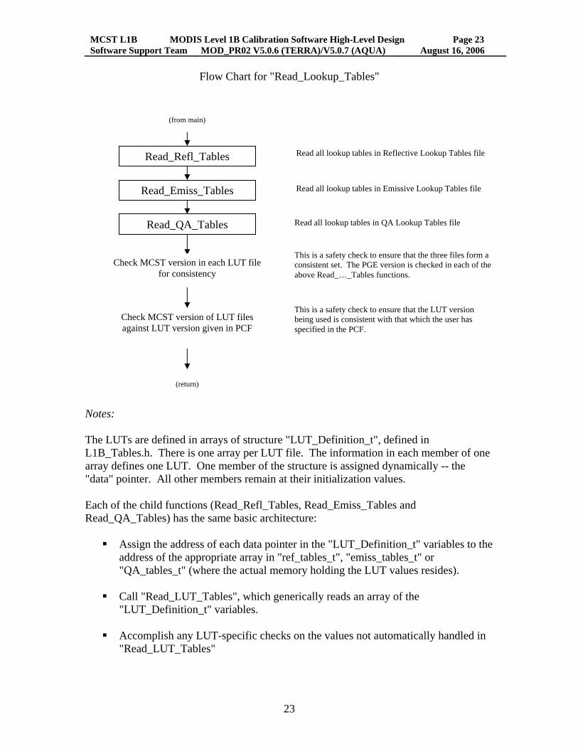
Flow Chart for "Read_Lookup_Tables" (from main)
Read all lookup tables in Reflective Lookup Tables file Read_Refl_Tables
Read_Emiss_Tables Read all lookup tables in Emissive Lookup Tables file
Check MCST version in each LUT file for consistency
Read_QA_Tables Read all lookup tables in QA Lookup Tables file
This is a safety check to ensure that the three files form a
consistent set. The PGE version is checked in each of the above Read_…_Tables functions.
This is a safety check to ensure that the LUT version being used is consistent with that which the user has specified in the PCF.
Check MCST version of LUT files against LUT version given in PCF
(return) Notes: The LUTs are defined in arrays of structure "LUT_Definition_t", defined in L1B_Tables.h. There is one array per LUT file. The information in each member of one array defines one LUT. One member of the structure is assigned dynamically -- the "data" pointer. All other members remain at their initialization values. Each of the child functions (Read_Refl_Tables, Read_Emiss_Tables and Read_QA_Tables) has the same basic architecture:
Assign the address of each data pointer in the "LUT_Definition_t" variables to the
address of the appropriate array in "ref_tables_t", "emiss_tables_t" or "QA_tables_t" (where the actual memory holding the LUT values resides).
Call "Read_LUT_Tables", which generically reads an array of the "LUT_Definition_t" variables.
Accomplish any LUT-specific checks on the values not automatically handled in "Read_LUT_Tables"

MCST L1B MODIS Level 1B Calibration Software High-Level Design Page 24 Software Support Team MOD_PR02 V5.0.6 (TERRA)/V5.0.7 (AQUA) August 16, 2006
24
Note: the code "generate_luts" links to the L1B_Tables modules and uses the same "LUT_Definition_t" arrays to write out the LUTs to the HDF file. When the definition of a LUT changes or LUTs are added or deleted, the "generate_luts" code needs to be recompiled.

MCST L1B MODIS Level 1B Calibration Software High-Level Design Page 25 Software Support Team MOD_PR02 V5.0.6 (TERRA)/V5.0.7 (AQUA) August 16, 2006
25
Flow Chart for "Preprocess_L1A_Data"
(from main) Calculate the frame-by-frame RVS correction terms for the reflective solar
bands and thermal emissive bands and store in the RSB_Cal_Coeff and Emiss_Cal_Coeff structures respectively.
Calculate RVS Correction
Compute the DN OBC averages for all reflective solar bands. Store in DN_OBC_Avg for writing to the OBC file and store in PP_Refl for use in reflective calibration.
Read data from following MOD01 granule needed for emissive calibration preprocessing from a subset of the total number of scans from the leading or trailing L1A granule. These data include the blackbody and space-view DNs, mirror side flags and engineering temperatures.
Read data from previous MOD01 granule needed for emissive calibration preprocessing from a subset of the total number of scans from the leading or trailing L1A granule. These data include the blackbody and space-view DNs, mirror side flags and engineering temperatures.
Read telemetry fields for Ecal-on for different kinds of bands, i.e. PV VIS, PV NIR, PV SM, PV LW and PC LW bands. If either A or B is on, set Ecal_On values for the corresponding bands for current scan to be true. If Ecal is on, the corresponding SV data can not be used for calibration.
For each scan of the middle granule, determine if the center of the moon lies within the space-view (SV) keep-out box (KOB). This sets values to be used later in determining the DN offset and for writing one of the "bit QA flags" in the scan metadata. (See [ALG-6])
Check if the nadir aperture door (NAD) door is closed. If the door is closed during any scan within the granule, set the dn_star_Min value to be -40 for those bands where dn_star_Min was set to 0. This allows system noise to be studied by MCST.
Open the current MOD01 granule for both SD and Vdata interface and read granule-related information needed for processing inside and outside the Preprocess module. File interfaces remain open after this function has executed and are not closed until after all scan-to-scan processing is completed.
Read_L1A_OBCEng
Adjust_dn_star_Min
Check_For_Moon_in_SV_KOB
Check_For_Ecal_ON
Read_Overlap_OBCEng
Read_Overlap_OBCEng
Process_OBCEng_Refl
Write OBC target scientific data sets and preprocess data scientific data sets, and copy scan level metadata scientific data sets, pixel quality scientific data sets, engineering memory scientific data sets, engineering vdata, SD Sun Azimuth, SD Sun Zenith, and DN OBC averages into L1B OBC file
Preprocess OBC and engineering data for Emissive Calibration. Calculate temperatures averaged over the granule and the ratio of the averaged temperature variance to prelaunch values, and the emissive calibration coefficients.
Process_OBCEng_Emiss
Write_L1B_OBCEng
(return)
MCST L1B MODIS Level 1B Calibration Software High-Level Design Page 26 Software Support Team MOD_PR02 V5.0.6 (TERRA)/V5.0.7 (AQUA) August 16, 2006
26
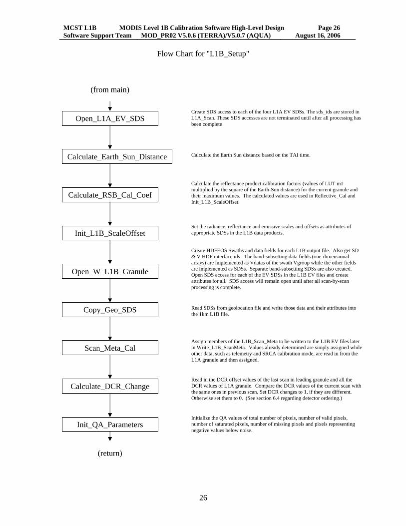
Flow Chart for "L1B_Setup"
(from main) Create SDS access to each of the four L1A EV SDSs. The sds_ids are stored in
L1A_Scan. These SDS accesses are not terminated until after all processing has been complete
Open_L1A_EV_SDS
Calculate_Earth_Sun_Distance Calculate the Earth Sun distance based on the TAI time.
Calculate the reflectance product calibration factors (values of LUT m1 multiplied by the square of the Earth-Sun distance) for the current granule and their maximum values. The calculated values are used in Reflective_Cal and Init_L1B_ScaleOffset.
Calculate_RSB_Cal_Coef
Set the radiance, reflectance and emissive scales and offsets as attributes of appropriate SDSs in the L1B data products.
Init_L1B_ScaleOffset
Create HDFEOS Swaths and data fields for each L1B output file. Also get SD & V HDF interface ids. The band-subsetting data fields (one-dimensional arrays) are implemented as Vdatas of the swath Vgroup while the other fields are implemented as SDSs. Separate band-subsetting SDSs are also created. Open SDS access for each of the EV SDSs in the L1B EV files and create attributes for all. SDS access will remain open until after all scan-by-scan processing is complete.
Open_W_L1B_Granule
Copy_Geo_SDS Read SDSs from geolocation file and write those data and their attributes into the 1km L1B file.
Assign members of the L1B_Scan_Meta to be written to the L1B EV files later in Write_L1B_ScanMeta. Values already determined are simply assigned while other data, such as telemetry and SRCA calibration mode, are read in from the L1A granule and then assigned.
Scan_Meta_Cal
Read in the DCR offset values of the last scan in leading granule and all the DCR values of L1A granule. Compare the DCR values of the current scan with the same ones in previous scan. Set DCR changes to 1, if they are different. Otherwise set them to 0. (See section 6.4 regarding detector ordering.)
Calculate_DCR_Change
Initialize the QA values of total number of pixels, number of valid pixels, number of saturated pixels, number of missing pixels and pixels representing negative values below noise.
Init_QA_Parameters
(return)

MCST L1B MODIS Level 1B Calibration Software High-Level Design Page 27 Software Support Team MOD_PR02 V5.0.6 (TERRA)/V5.0.7 (AQUA) August 16, 2006
27
PDL for "Emissive_Cal" BEGIN PDL Initialize some indexes and variables, check inputs. LOOP through all bands of the 1km night resolution
IF band is band 26 (a reflective band) Increment detector index by 10 and skip to next band.
END IF LOOP through all detectors
Accomplish uncertainty-related calculations that are independent of frame. LOOP through all frames
Assign DN_ev from appropriate L1A array element. IF L1A DN value corresponds to missing
Assign L1A_DN_MISSING_SI to the scaled integer variable. Assign BAD_DATA_UI to the uncertainty index variable. Increment the missing pixels variable. Decrement the valid pixels variable. Trip the bad data flag variable. Skip to next frame.
END IF (make similar checks as above for dead detector, sector rotation, saturated pixel, moon in space view port, invalid space view DN average, and negative calibration coefficient)
Compute dn by subtracting the average space view DN value from the DN value.
IF PCX correction switch is on and instrument is MODIS/Terra (PFM) IF band is band 31
Save the dn value in an array for use with subsequent bands ELSE IF band is one of the MODIS bands 32 through 36
Form the cross talk correction to dn and add to dn END IF
END IF Compute L_ev radiance using algorithms in the algorithms documents. IF radiance exceeds the maximum for scaling to SI
Assign TEB_OR_RSB_GT_MAX_SI to the scaled integer variable. Assign BAD_DATA_UI to the uncertainty index variable. Increment the missing pixels variable. Decrement the valid pixels variable. Trip the bad data flag variable. Skip to next frame.
END IF IF radiance is less than - NeDL (the LUT value)
Flip the "flag" to 1 (used to set a QA item later)

MCST L1B MODIS Level 1B Calibration Software High-Level Design Page 28 Software Support Team MOD_PR02 V5.0.6 (TERRA)/V5.0.7 (AQUA) August 16, 2006
28
Increment variable negative_value_below_noise_pixels Decrement valid pixels variable Trip the bad data flag for this band
(note that we do not set an unusable data value for SI) END IF Convert the radiance to scaled integer and store in the L1B scan (if the
radiance is less than the minimum for scaling, set SI to 0, which is equivalent to saying that the radiance equals the minimum for scaling)
IF radiance <= 0 or dn is <= 0 or the nadir aperture door is closed Set uncertainty index to BAD_DATA_UI
ELSE compute and assign uncertainty index
END IF END LOOP over frames
END LOOP over detectors increment B_emiss
END LOOP over bands IF the "flag" value has been tripped
Set the Bit_QA_Flags value that negative below noise occurred END IF
END PDL
MCST L1B MODIS Level 1B Calibration Software High-Level Design Page 29 Software Support Team MOD_PR02 V5.0.6 (TERRA)/V5.0.7 (AQUA) August 16, 2006
29
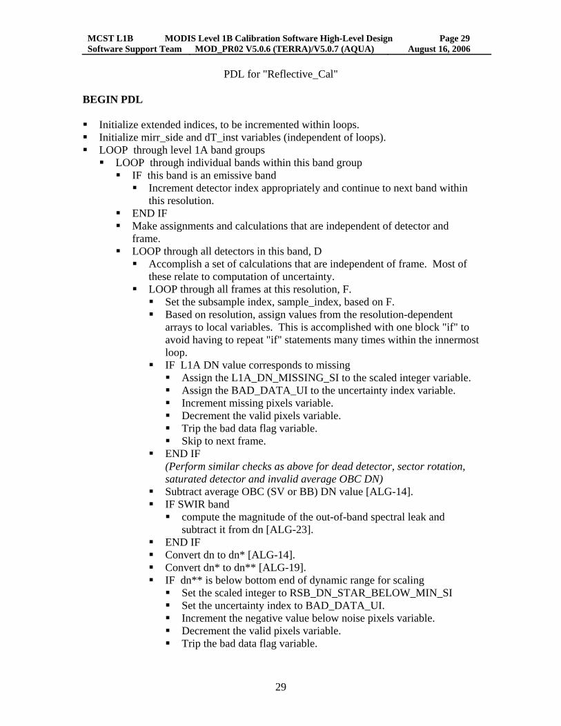
PDL for "Reflective_Cal" BEGIN PDL Initialize extended indices, to be incremented within loops. Initialize mirr_side and dT_inst variables (independent of loops). LOOP through level 1A band groups
LOOP through individual bands within this band group IF this band is an emissive band
Increment detector index appropriately and continue to next band within this resolution.
END IF Make assignments and calculations that are independent of detector and
frame. LOOP through all detectors in this band, D
Accomplish a set of calculations that are independent of frame. Most of these relate to computation of uncertainty.
LOOP through all frames at this resolution, F. Set the subsample index, sample_index, based on F. Based on resolution, assign values from the resolution-dependent
arrays to local variables. This is accomplished with one block "if" to avoid having to repeat "if" statements many times within the innermost loop.
IF L1A DN value corresponds to missing Assign the L1A_DN_MISSING_SI to the scaled integer variable. Assign the BAD_DATA_UI to the uncertainty index variable. Increment missing pixels variable. Decrement the valid pixels variable. Trip the bad data flag variable. Skip to next frame.
END IF (Perform similar checks as above for dead detector, sector rotation, saturated detector and invalid average OBC DN)
Subtract average OBC (SV or BB) DN value [ALG-14]. IF SWIR band
compute the magnitude of the out-of-band spectral leak and subtract it from dn [ALG-23].
END IF Convert dn to dn* [ALG-14]. Convert dn* to dn** [ALG-19]. IF dn** is below bottom end of dynamic range for scaling
Set the scaled integer to RSB_DN_STAR_BELOW_MIN_SI Set the uncertainty index to BAD_DATA_UI. Increment the negative value below noise pixels variable. Decrement the valid pixels variable. Trip the bad data flag variable.

MCST L1B MODIS Level 1B Calibration Software High-Level Design Page 30 Software Support Team MOD_PR02 V5.0.6 (TERRA)/V5.0.7 (AQUA) August 16, 2006
30
Skip to next frame. ELSE IF dn** is above the end of dynamic range for scaling
Set the scaled integer to TEB_OR_RSB_GT_MAX _SI Set the uncertainty index to BAD_DATA_UI. Increment the negative value below noise pixels variable. Decrement the valid pixels variable. Trip the bad data flag variable. Skip to next frame.
ELSE Convert dn** to the scaled integer
END IF IF nadir aperture door is closed
Set the most significant bit of the scaled integer, up to the maximum specified in the file specs.
END IF IF dn <= 0 or dn* <= 0 or temperature correction was not valid or
NAD is closed Set uncertainty index to BAD_DATA_UI
ELSE Compute percent uncertainty [ALG-21] Convert to uncertainty index
END IF END LOOP over frames at resolution
END LOOP over detectors END LOOP over bands
END LOOP over resolutions END PDL
MCST L1B MODIS Level 1B Calibration Software High-Level Design Page 31 Software Support Team MOD_PR02 V5.0.6 (TERRA)/V5.0.7 (AQUA) August 16, 2006
31
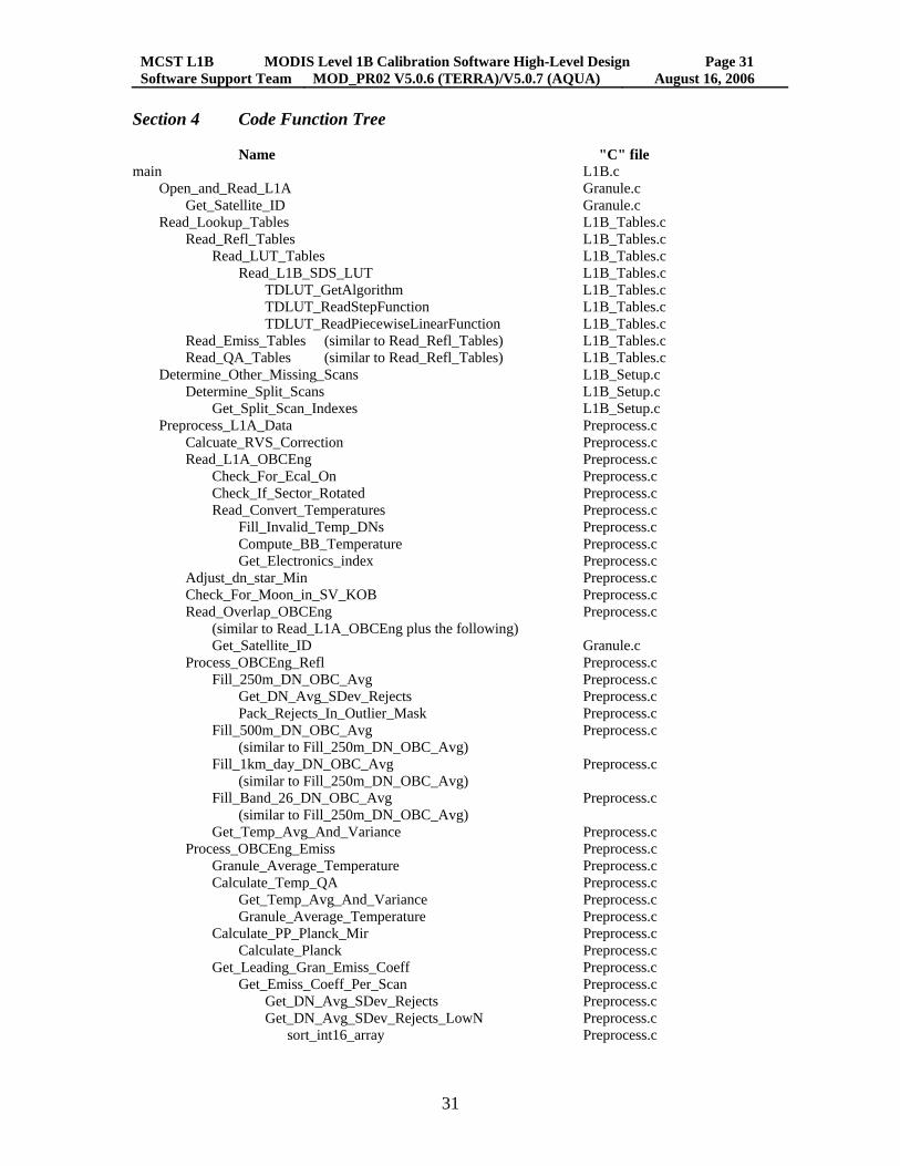
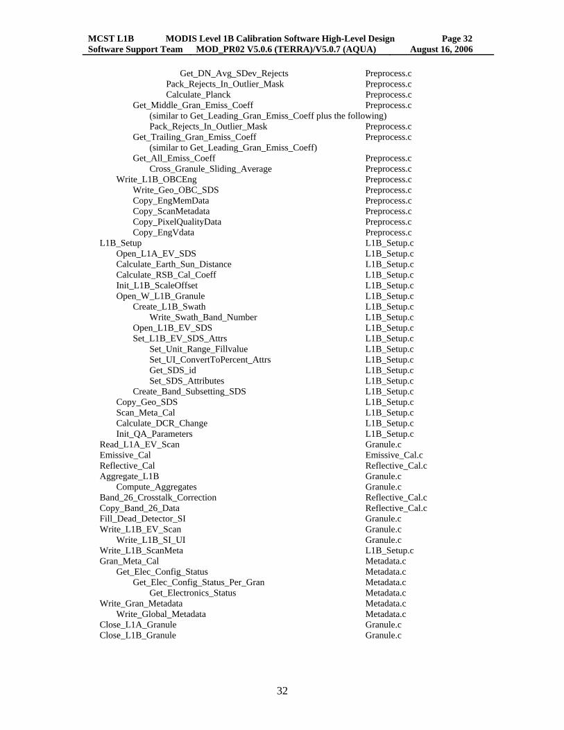
Section 4 Code Function Tree Name "C" file main L1B.c Open_and_Read_L1A Granule.c Get_Satellite_ID Granule.c Read_Lookup_Tables L1B_Tables.c Read_Refl_Tables L1B_Tables.c Read_LUT_Tables L1B_Tables.c Read_L1B_SDS_LUT L1B_Tables.c TDLUT_GetAlgorithm L1B_Tables.c TDLUT_ReadStepFunction L1B_Tables.c TDLUT_ReadPiecewiseLinearFunction L1B_Tables.c Read_Emiss_Tables (similar to Read_Refl_Tables) L1B_Tables.c Read_QA_Tables (similar to Read_Refl_Tables) L1B_Tables.c Determine_Other_Missing_Scans L1B_Setup.c Determine_Split_Scans L1B_Setup.c Get_Split_Scan_Indexes L1B_Setup.c Preprocess_L1A_Data Preprocess.c Calcuate_RVS_Correction Preprocess.c Read_L1A_OBCEng Preprocess.c Check_For_Ecal_On Preprocess.c Check_If_Sector_Rotated Preprocess.c Read_Convert_Temperatures Preprocess.c Fill_Invalid_Temp_DNs Preprocess.c Compute_BB_Temperature Preprocess.c Get_Electronics_index Preprocess.c Adjust_dn_star_Min Preprocess.c Check_For_Moon_in_SV_KOB Preprocess.c Read_Overlap_OBCEng Preprocess.c (similar to Read_L1A_OBCEng plus the following) Get_Satellite_ID Granule.c Process_OBCEng_Refl Preprocess.c Fill_250m_DN_OBC_Avg Preprocess.c Get_DN_Avg_SDev_Rejects Preprocess.c Pack_Rejects_In_Outlier_Mask Preprocess.c Fill_500m_DN_OBC_Avg Preprocess.c (similar to Fill_250m_DN_OBC_Avg) Fill_1km_day_DN_OBC_Avg Preprocess.c (similar to Fill_250m_DN_OBC_Avg) Fill_Band_26_DN_OBC_Avg Preprocess.c (similar to Fill_250m_DN_OBC_Avg) Get_Temp_Avg_And_Variance Preprocess.c Process_OBCEng_Emiss Preprocess.c Granule_Average_Temperature Preprocess.c Calculate_Temp_QA Preprocess.c Get_Temp_Avg_And_Variance Preprocess.c Granule_Average_Temperature Preprocess.c Calculate_PP_Planck_Mir Preprocess.c Calculate_Planck Preprocess.c Get_Leading_Gran_Emiss_Coeff Preprocess.c Get_Emiss_Coeff_Per_Scan Preprocess.c Get_DN_Avg_SDev_Rejects Preprocess.c Get_DN_Avg_SDev_Rejects_LowN Preprocess.c sort_int16_array Preprocess.c
MCST L1B MODIS Level 1B Calibration Software High-Level Design Page 32 Software Support Team MOD_PR02 V5.0.6 (TERRA)/V5.0.7 (AQUA) August 16, 2006
32
Get_DN_Avg_SDev_Rejects Preprocess.c Pack_Rejects_In_Outlier_Mask Preprocess.c Calculate_Planck Preprocess.c Get_Middle_Gran_Emiss_Coeff Preprocess.c (similar to Get_Leading_Gran_Emiss_Coeff plus the following) Pack_Rejects_In_Outlier_Mask Preprocess.c Get_Trailing_Gran_Emiss_Coeff Preprocess.c (similar to Get_Leading_Gran_Emiss_Coeff) Get_All_Emiss_Coeff Preprocess.c Cross_Granule_Sliding_Average Preprocess.c Write_L1B_OBCEng Preprocess.c Write_Geo_OBC_SDS Preprocess.c Copy_EngMemData Preprocess.c Copy_ScanMetadata Preprocess.c Copy_PixelQualityData Preprocess.c Copy_EngVdata Preprocess.c L1B_Setup L1B_Setup.c Open_L1A_EV_SDS L1B_Setup.c Calculate_Earth_Sun_Distance L1B_Setup.c Calculate_RSB_Cal_Coeff L1B_Setup.c Init_L1B_ScaleOffset L1B_Setup.c Open_W_L1B_Granule L1B_Setup.c Create_L1B_Swath L1B_Setup.c Write_Swath_Band_Number L1B_Setup.c Open_L1B_EV_SDS L1B_Setup.c Set_L1B_EV_SDS_Attrs L1B_Setup.c Set_Unit_Range_Fillvalue L1B_Setup.c Set_UI_ConvertToPercent_Attrs L1B_Setup.c Get_SDS_id L1B_Setup.c Set_SDS_Attributes L1B_Setup.c Create_Band_Subsetting_SDS L1B_Setup.c Copy_Geo_SDS L1B_Setup.c Scan_Meta_Cal L1B_Setup.c Calculate_DCR_Change L1B_Setup.c Init_QA_Parameters L1B_Setup.c Read_L1A_EV_Scan Granule.c Emissive_Cal Emissive_Cal.c Reflective_Cal Reflective_Cal.c Aggregate_L1B Granule.c Compute_Aggregates Granule.c Band_26_Crosstalk_Correction Reflective_Cal.c Copy_Band_26_Data Reflective_Cal.c Fill_Dead_Detector_SI Granule.c Write_L1B_EV_Scan Granule.c Write_L1B_SI_UI Granule.c Write_L1B_ScanMeta L1B_Setup.c Gran_Meta_Cal Metadata.c Get_Elec_Config_Status Metadata.c Get_Elec_Config_Status_Per_Gran Metadata.c Get_Electronics_Status Metadata.c Write_Gran_Metadata Metadata.c Write_Global_Metadata Metadata.c Close_L1A_Granule Granule.c Close_L1B_Granule Granule.c

MCST L1B MODIS Level 1B Calibration Software High-Level Design Page 33 Software Support Team MOD_PR02 V5.0.6 (TERRA)/V5.0.7 (AQUA) August 16, 2006
33
Section 5 Miscellaneous Implementation Notes This section provides miscellaneous implementation notes that are of importance to developers:
Variance and Standard Deviation Formulas Used in Level 1B Platform-Dependent Behavior In Math Functions Presence of Band 26 SDSs and Implementation Detector order conventions Impact of missing MOD01 scan data Split scans
5.1 Variance and Standard Deviation Formulas Used in Level 1B The variance is defined to be the square of the standard deviation, σ. Calculations of variance or σ are used in several places in Level 1B. This section summarizes the formulas used and the implementation issues. Approximation to variance of probability distribution:
var =1
N −1(xi − x
i=1
N
∑ )2 (5.1.1)
Mathematically equivalent formula:
var =1
N −1[ xi
2
i=1
N
∑ − 1N ( xi )(
i=1
N
∑ xi )]i=1
N
∑ (5.1.2)
We use Equation 5.1.2 in Level 1B because it is simpler to code and is computationally more efficient than Equation 5.1.1. However, Eq. 5.1.2 was found to be numerically inaccurate at the float32 precision level for some calculations in Level 1B. Essentially, two very large numbers were being subtracted from each other and needed precision was lost. These calculations affected only the temperature QA metadata. We have implemented the code using double precision in all places (type "double") to reduce the loss of accuracy in these calculations.
5.2 Platform-Dependent Behavior in Math Functions When porting MOD_PR02 from the development SGI platform to a DEC ALPHA, discrepancies arose due to the use of some math library functions ("pow", for example). Although there were no warnings generated in compilation, the DEC ALPHA required
MCST L1B MODIS Level 1B Calibration Software High-Level Design Page 34 Software Support Team MOD_PR02 V5.0.6 (TERRA)/V5.0.7 (AQUA) August 16, 2006
34
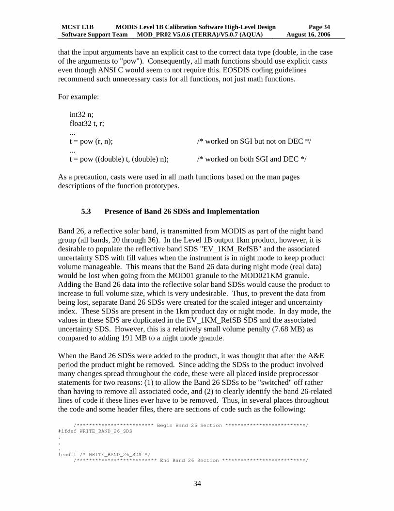
that the input arguments have an explicit cast to the correct data type (double, in the case of the arguments to "pow"). Consequently, all math functions should use explicit casts even though ANSI C would seem to not require this. EOSDIS coding guidelines recommend such unnecessary casts for all functions, not just math functions. For example:
int32 n; float32 t, r; ... t = pow (r, n); /* worked on SGI but not on DEC */ ... t = pow ((double) t, (double) n); /* worked on both SGI and DEC */
As a precaution, casts were used in all math functions based on the man pages descriptions of the function prototypes.
5.3 Presence of Band 26 SDSs and Implementation Band 26, a reflective solar band, is transmitted from MODIS as part of the night band group (all bands, 20 through 36). In the Level 1B output 1km product, however, it is desirable to populate the reflective band SDS "EV_1KM_RefSB" and the associated uncertainty SDS with fill values when the instrument is in night mode to keep product volume manageable. This means that the Band 26 data during night mode (real data) would be lost when going from the MOD01 granule to the MOD021KM granule. Adding the Band 26 data into the reflective solar band SDSs would cause the product to increase to full volume size, which is very undesirable. Thus, to prevent the data from being lost, separate Band 26 SDSs were created for the scaled integer and uncertainty index. These SDSs are present in the 1km product day or night mode. In day mode, the values in these SDS are duplicated in the EV_1KM_RefSB SDS and the associated uncertainty SDS. However, this is a relatively small volume penalty (7.68 MB) as compared to adding 191 MB to a night mode granule. When the Band 26 SDSs were added to the product, it was thought that after the A&E period the product might be removed. Since adding the SDSs to the product involved many changes spread throughout the code, these were all placed inside preprocessor statements for two reasons: (1) to allow the Band 26 SDSs to be "switched" off rather than having to remove all associated code, and (2) to clearly identify the band 26-related lines of code if these lines ever have to be removed. Thus, in several places throughout the code and some header files, there are sections of code such as the following: /************************* Begin Band 26 Section **************************/ #ifdef WRITE_BAND_26_SDS . . . #endif /* WRITE_BAND_26_SDS */ /************************** End Band 26 Section ***************************/

MCST L1B MODIS Level 1B Calibration Software High-Level Design Page 35 Software Support Team MOD_PR02 V5.0.6 (TERRA)/V5.0.7 (AQUA) August 16, 2006
35
The code lines enclosed in the #ifdef block are only Band-26-related lines of code. Currently, the macro WRITE_BAND_26_SDS is defined (Granule.h). If the definition is removed or commented out, then the Band 26 SDSs will not be written to the 1km product and no other changes should occur in any other data item in the products. The Band 26 product is currently being produced, however (as of August 16, 2006).
5.4 Detector Order Conventions There are two detector order conventions implicit within the Level 1B data products: "SBRS order": Increasing detector number is opposite to the satellite track direction
(this is the convention of the manufacturer -- Santa Barbara Research Systems). "product order": Increasing detector number is along the satellite track direction (this
allows consecutive scans to be easily concatenated to form an image). Table 5.1 below summarizes the conventions implied in the input and output data for MOD_PR02 (Level 0 is not an input, but is included for reference):
Table 5.1 Summary of Detector Order Convention in Files related to MOD_PR02
File type Convention: data applied to Level 0 SBRS order: all data MOD01 product order: sector DN data (EV, BB, SD, SRCA, SV)
SBRS order: all other data Level 1B LUT HDF files product order: all data MOD021KM, MOD02HKM, MOD02QKM
product order: all data
MOD02OBC SBRS order: "fpa_dcr_offsets", "raw_pv_gains" product order: all other data
The ordering of all data in the Level 0 file follows the SBRS convention. MOD_PR01 ingests the Level 0 file and reverses the detector order of the digital number data for the Earth view (EV), blackbody (BB), space-view (SV), solar diffuser (SD) and spectroradiometric calibration assembly (SRCA) sectors. All other data in the MOD01 granule remain in SBRS order. All detector-dependent lookup table inputs to MOD_PR02 are in product order. Since MOD_PR01 has already reversed the detector order of the sector DN data, no detector order reversal is needed within MOD_PR02 to calibrate the science data. However, to obtain all data in the EV products to have detector order in "product" order, the detector order of the DCR SDSs of MOD01 (in SBRS order) are reversed in function Calculate_DCR_Change to yield product order for all DCR change SDSs in the MOD02 products. No other detector order reversals are accomplished in MOD_PR02.

MCST L1B MODIS Level 1B Calibration Software High-Level Design Page 36 Software Support Team MOD_PR02 V5.0.6 (TERRA)/V5.0.7 (AQUA) August 16, 2006
36
The net result of the above is that all three EV products of MOD_PR02 have the product order convention for all data. However, two data sets in the OBC file remain in SBRS order.
5.5 Impact of Missing MOD01 Scan Data The following situations have occurred: (1) a MOD01 granule has scans flagged as completely missing (containing no valid data) and (2) a MOD01 granule may be "empty" (the number of scans is zero). In MOD01 test granules provided by SDST, the situation of completely missing scans occurred one time. A test granule had the first 32 scans of sector data missing (although the engineering Vdata for these scans did not appear to be missing). For the scans identified as having no valid data:
the first element of the MOD01 SDS "Scan quality array" for those scans were set
to 0 (zero), the "Mirror Side" values were set to -1 (not described in the current MOD01 file
specification), the "Scan Type" was set to "Other", and the sector DN values for those scans were set to -32767 (not described in the
current MOD01 file specification) rather than -1 (which should be that "missing" DN value).
Within MOD_PR02, the above conditions influenced the design of "main" and various functions called by "Preprocess_L1A_Data". Within "main", the Scan quality array is used to determine a completely missing scan. Since the mirror side is used as an index in arrays, it must be checked prior to use. In the initial MODIS data processed at the GDAAC, some "empty" MOD01 granules were produced. These granules had the "Number of Scans" attribute set to zero. If this occurs for the current MOD01 granule, MOD_PR02 errors out under the assumption that processing for higher order PGEs should not be carried out. A special failure exit code of 233 is used as a flag for operations personnel (all other failures result in an exit code of 1). However, if this occurs for the previous or following MOD01 granule, MOD_PR02 will continue processing the scans of the current granule. When sliding averages over scan are computed which normally would need the scan data from the previous or following granules, the code essentially ignores the missing scans, resulting in a reduced baseline of data for the averages near the temporal boundary of the current granule.
5.6 Split Scans A single scan which "splits" may appear in the MOD01 product as the result of corruption in the Level 0 packet header (such as a corrupted timestamp). The characteristics of the split scan are typically:

MCST L1B MODIS Level 1B Calibration Software High-Level Design Page 37 Software Support Team MOD_PR02 V5.0.6 (TERRA)/V5.0.7 (AQUA) August 16, 2006
37
A repeated time, such as SD start time, A repeated mirror side value, and A low frame count on some sectors in one scan and a low frame count on the other
sectors of the adjacent scan. The consequences of the split scan include EV missing data in the Level 1B images, greater than 204 scans in some granules and missing calibration sector data in some scans, preventing calibration of the EV data. In Version 2.4.1 of the MOD_PR02 code, the following was incorporated to address the split scan problem:
Macros were raised to allow up to 208 scans (the previous limit was 204 scans). An algorithm was included to detect a split scan. When a split scan is detected, the code treats the EV data as "entirely missing
scan" (65535 value of scaled integer), for both parts of the split scan. MOD_PR01 code has been modified to reduce (but not eliminate) the incidences of split scans. To maximize the calibrated output, the L1B code was modified to make detection of these optional (through a control switch in a LUT). One of the consequences of the MOD_PR01 code modification is that the second element of the scan quality array was often negative due to a counting bug in L1A code, though this has since been fixed. Rather than treating the scan as missing, a control switch allows the L1B code to ignore the invalid value and calibrate the scan.

MCST L1B MODIS Level 1B Calibration Software High-Level Design Page 38 Software Support Team MOD_PR02 V5.0.6 (TERRA)/V5.0.7 (AQUA) August 16, 2006
38
Section 6 Acronyms ASCII American Standard Code for Information Interchange, a machine-portable
data file format, used to represent text. BB Black Body (one of the on-board calibrators of MODIS) DAAC Distributed Data Active Archive Center DN Digital number -- upper case refers to uncorrected (raw) value as recorded
by the MODIS instrument dn Digital Number -- lower case refers to DN corrected for the electronic
background (zero point) DN value. dn* For reflective bands, this is dn corrected for all known instrument effects
such as temperature effects and mirror side response vs. scan angle (RVS). ECS EOS Core System EOS Earth Observing System. EV Earth View FPA focal plane assembly geolocation The geolocation code (same as MOD_PR03) ingests an intermediate L1A
granule and generates geolocation quantities (latitude, longitude, etc.) for the 5-minute granule.
GSFC Goddard Space Flight Center GDAAC Goddard Space Flight Center Distributed Data Active Archive Center HDF Hierarchical Data Format. The format was developed and is maintained by
the National Center for Supercomputing Applications (NCSA) at the University of Illinois at Urbana-Champaign
HDF-EOS Hierarchical Data Format-Earth Observing System and the software library that implements it.
L1A Level 1A -- in general, the algorithms and code which transform the 2-hour binary Level 0 MODIS file to a set of 5-minute duration HDF files.
L1B Level 1B -- in general, the algorithms and code which are used to calibrate the MODIS data stored in a Level 1A file.
LUT Look-Up Table. Generally an input value or array to the L1B code which resides in one of three files: the Emissive Lookup Tables file, the Reflective Lookup Tables file, or the QA Lookup Tables file.
LWIR Long-Wave Infrared -- usually refers to MODIS bands 27-36. MCF Metadata configuration file -- a necessary input for the SDP toolkit for
creating ECS core and archive metadata. Defined the basic structure and valid contents for the metadata. In some cases, values placed into the output products are defined within the MCF.
MCST MODIS Characterization Support Team MODIS Moderate Resolution Imaging Spectro-Radiometer MODAPS MODIS Adaptive Processing System MOD_PR MODIS Process -- leading part of the name of any major processing code
in the MODIS data processing system (the L1A code is MOD_PR01, the L1B code is MOD_PR02, etc.)

MCST L1B MODIS Level 1B Calibration Software High-Level Design Page 39 Software Support Team MOD_PR02 V5.0.6 (TERRA)/V5.0.7 (AQUA) August 16, 2006
39
MWIR Medium-Wave Infrared -- usually refers to MODIS bands 20, 21, 22, 23, 24, 25
NASA National Aeronautics and Space Administration NCSA National Center for Supercomputing Applications -- the developers of
HDF. NIR Near Infrared -- usually refers to the following MODIS bands: 1, 2, 13lo,
13hi, 14lo, 14hi, 15, 16, 17, 18, 19 OBC On Board Calibrator -- usually one of the following: Solar diffuser (SD),
spectro-radiometric calibration assembly (SRCA), blackbody (BB), space-view (SV).
PCF Process Control File -- a necessary input for any process which utilizes the SDP toolkit. Contains the logical unit numbers (LUNs) and universal references (URs) for the input files, LUT files, and output files for the code being run as well as LUNs for other inputs and outputs.
PFM Prototype Flight Model -- the MODIS instrument on board the Terra satellite.
PGE Process Generation Executive -- Run by MODAPS, contains one or more processes generating the data products stored by MODAPS. PGE01 contains MOD_PR01 and MOD_PR03. PGE02 contains MOD_PR02 and MOD_PR02QA.
QA Quality Assurance RSB or RefSB
Reflective Solar bands -- MODIS bands 1-12, 13lo, 13hi, 14lo, 14hi, 15-19, 26
SD Solar Diffuser (one of the on-board calibrators of MODIS) or Science Data (in the context of HDF).
SDP Science Data Processing -- Name for the toolkit developed and used by ECS for the MODIS project.
SDS Scientific Data Set. One of the basic HDF data types. Consists of a self-describing multi-dimensional array of numbers and various attributes associated with those numbers.
SDST Science Data Support Team SRCA Spectro-Radiometric Calibration Assembly (one of the on-board
calibrators of MODIS) SV Space-View (used to establish the electronic zero point of MODIS
detectors) SWIR Short-wave infrared -- generally refers to MODIS bands 5,6,7 and 26 TBD To Be Defined or Determined TEB Thermal emissive bands -- MODIS bands 20-25, 27-36 UR Universal Reference Vdata One of the basic HDF data types. Equivalent to a data base or table having
a set of records with each record having a common set of fields. VIS Visual -- refers to the following MODIS bands: 3, 4, 8, 9, 10, 11, 12
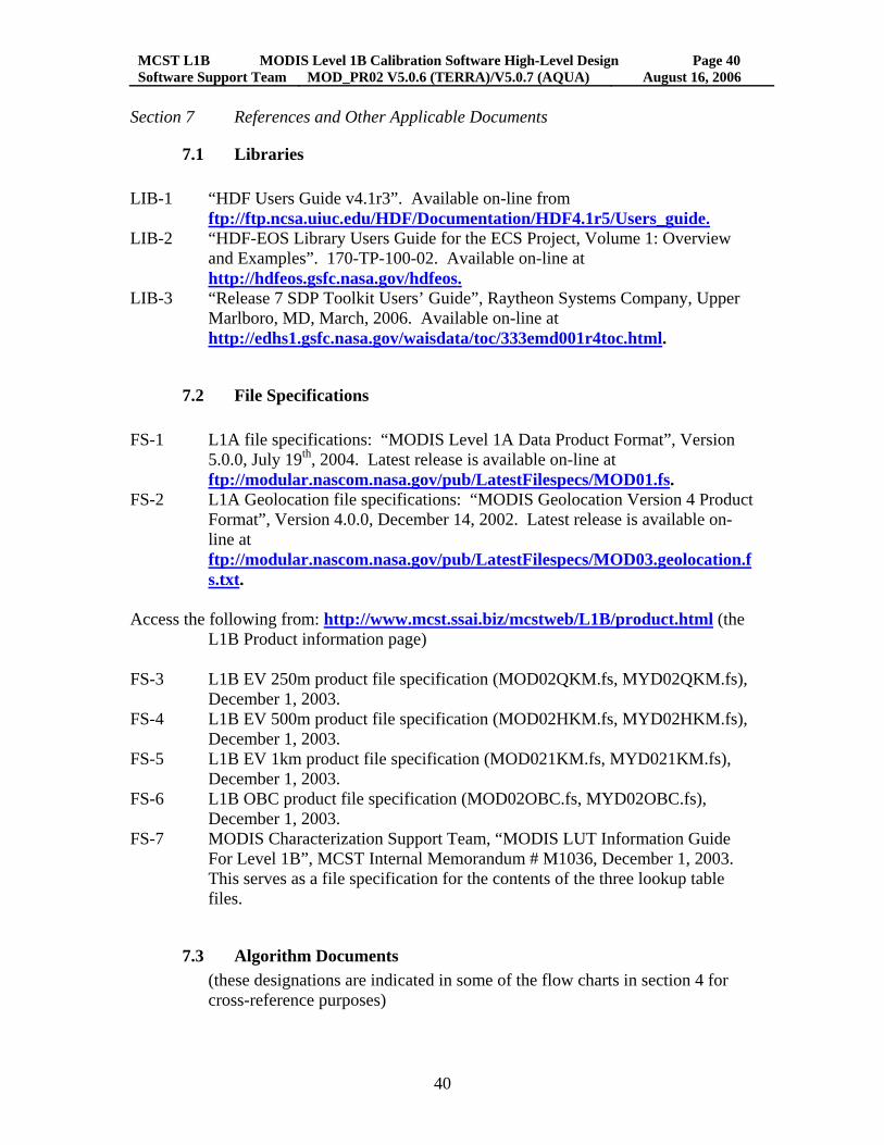
MCST L1B MODIS Level 1B Calibration Software High-Level Design Page 40 Software Support Team MOD_PR02 V5.0.6 (TERRA)/V5.0.7 (AQUA) August 16, 2006
40
Section 7 References and Other Applicable Documents
7.1 Libraries LIB-1 “HDF Users Guide v4.1r3”. Available on-line from
ftp://ftp.ncsa.uiuc.edu/HDF/Documentation/HDF4.1r5/Users_guide.LIB-2 “HDF-EOS Library Users Guide for the ECS Project, Volume 1: Overview
and Examples”. 170-TP-100-02. Available on-line at http://hdfeos.gsfc.nasa.gov/hdfeos.
LIB-3 “Release 7 SDP Toolkit Users’ Guide”, Raytheon Systems Company, Upper Marlboro, MD, March, 2006. Available on-line at http://edhs1.gsfc.nasa.gov/waisdata/toc/333emd001r4toc.html.
7.2 File Specifications FS-1 L1A file specifications: “MODIS Level 1A Data Product Format”, Version
5.0.0, July 19th, 2004. Latest release is available on-line at ftp://modular.nascom.nasa.gov/pub/LatestFilespecs/MOD01.fs.
FS-2 L1A Geolocation file specifications: “MODIS Geolocation Version 4 Product Format”, Version 4.0.0, December 14, 2002. Latest release is available on-line at ftp://modular.nascom.nasa.gov/pub/LatestFilespecs/MOD03.geolocation.fs.txt.
Access the following from: http://www.mcst.ssai.biz/mcstweb/L1B/product.html (the
L1B Product information page) FS-3 L1B EV 250m product file specification (MOD02QKM.fs, MYD02QKM.fs),
December 1, 2003. FS-4 L1B EV 500m product file specification (MOD02HKM.fs, MYD02HKM.fs),
December 1, 2003. FS-5 L1B EV 1km product file specification (MOD021KM.fs, MYD021KM.fs),
December 1, 2003. FS-6 L1B OBC product file specification (MOD02OBC.fs, MYD02OBC.fs),
December 1, 2003. FS-7 MODIS Characterization Support Team, “MODIS LUT Information Guide
For Level 1B”, MCST Internal Memorandum # M1036, December 1, 2003. This serves as a file specification for the contents of the three lookup table files.
7.3 Algorithm Documents (these designations are indicated in some of the flow charts in section 4 for cross-reference purposes)

MCST L1B MODIS Level 1B Calibration Software High-Level Design Page 41 Software Support Team MOD_PR02 V5.0.6 (TERRA)/V5.0.7 (AQUA) August 16, 2006
41
ATBD "MODIS Level 1B Algorithm Theoretical Basis Document Version 2.0 [ATBD-MOD-01]", Draft, MCM-ATBD-01-U-DNCN, May, 1997
(The ATBD has been amended/superceded by the following)
ALG-1 Guenther, B., G. D. Godden, X. Xiong, E.J. Knight, S. Y. Qiu,
H. Montgomery, M. M. Hopkins, M. G. Khayat, and Z. Hao, “Prelaunch Algorithm and Data Format for the Level 1B Calibration Products for the EOS AM-1 Moderate Resolution Imaging Spectroradiometer (MODIS)”, IEEE Transactions on Geoscience and Remote Sensing, 36, 1142 (1998).
ALG-2 “Reflective Band Calibration Algorithm Change Design Document for Version 2.1 of the MODIS Level 1B Software System”, MODIS Characterization Support Team (MCST).
ALG-3 Xiong, X., and Dorman, T., “Preliminary Investigation of the On-Board Calibrator (OBC) Blackbody Temperature Calibration Algorithm”, MCST Internal Memorandum, March 24, 1998.
ALG-4 Xiong, X., “Prototype On-Orbit L vs. DN Algorithm for MODIS Thermal Emissive Bands (Update 2)”, MCST Internal Memorandum # M0133, March 10, 1998.
ALG-5 Xiong, X., and G. Godden, “MODIS PC Bands Crosstalk Correction Algorithm for L1B Coding”, MCST Internal Memorandum # M0215, March 9, 1998.
ALG-6 Godden, G. et. al., "A common algorithm for handling the instrument and electronic backgrounds for the reflective and thermal bands", MCST Internal Memorandum # M0656, April 28, 1999.
ALG-7 McKay, A., miscellaneous notes, dated February 2, 1999. ALG-8 Rogers, J., "Moon in Space View Port -- notes on translation of Al McKay's
Algorithm to Equations for input to L1B". ALG-9 Berriman, G.B. and G. Fireman, "Handling of Reflectance and Radiance
Calibration Scales of Reflective Solar Bands Inside Level 1B", MCST Internal Memorandum # M0652, April 22 1999. (Revised May 7, 1999)
ALG-10 Fireman, G. and B. Berriman, , "Handling of Saturation of PFM Reflective Band Detectors inside Level 1B", MCST Internal Memorandum # M0657, April 28 1999.
ALG-11 Chiang, K.,and X. Xiong, "Changes in the Calibration Algorithm and LUT due to RVS and the Updated Fitting Method for Thermal Emissive Infrared Bands", MCST Internal Memorandum # M0651, April 22, 1999.
ALG-12 Xiong, X., X. Wang and G. Godden, "LUT Formats for OBC Emissivity, OBC Temperature Offset, and Scan Cavity Emissivity (Update 1)", MCST Internal Memorandum # M0639, May 6, 1999.
ALG-13 Xiong, X., et. al., “A Common Algorithm for Computing the Instrument Temperature in the L1B Code and New LUT Format”, MCST Internal Memorandum # MO677, May 9, 1999.
ALG-14 Berriman, B. and G. Reichert, "Level 1B Uncertainty Calculations for Reflective Solar Bands", MCST Internal Memorandum # M0703, May 27, 1999.

MCST L1B MODIS Level 1B Calibration Software High-Level Design Page 42 Software Support Team MOD_PR02 V5.0.6 (TERRA)/V5.0.7 (AQUA) August 16, 2006
42
ALG-15 Xiong, X. et. al., "Thermal Sensors Selected for MODIS Scan Cavity Temperature and its Computing Algorithm", MCST Internal Memorandum # M0678, May 12, 1999.
ALG-16 Rogers, J. and X. Xiong, "Algorithm Modification for Computing MODIS Instrument Temperature in L1B Code", MCST Internal Memorandum # M0681, May 13, 1999.
ALG-17 Adimi, F. et. al., "ADC Correction Algorithm for all bands", MCST Internal Memorandum # M0765, July 30, 1999.
ALG-18 Fireman, G., "Detector Quality Flag LUT Criteria Revision", MCST Internal Memorandum # M0914, June 23, 2000.
ALG-19 Berriman, B., "Calculation of the Digital Signals Written to the Level 1B Data Products for the Reflective Solar Bands", MCST Internal Memorandum # M0825, October 27, 1999.
ALG-20 Chiang, K. et. al., "PFM Reflectance Uncertainty Algorithm (ReflUncert) - update 2", MCST Internal Memorandum, November 24, 1999.
ALG-21 Chiang, K., "PFM TEB Radiometric Uncertainty and LUT Format -- Update 2", MCST Internal Memorandum # M0792, December 6, 1999.
ALG-22 Esposito, J., and B. Berriman, "How to Determine Whether the MODIS Nadir Pixel Sees Day or Night", November 1, 1999.
ALG-23 Xiong, X., "SWIR Correction Algorithm Change in L1B", MCST Internal Memo, December 1, 2000.
7.4 Other documents OTH-1 “MODIS Command, Telemetry, Science and Engineering Description”,
Document 151840, Release C, Santa Barbara Research Center, August 2000. Available on-line at ftp://ftp.mcst.ssai.biz/pub/permanent/IOT/document_archive/SBRS_151840_Rev_C.zip.
7.5 Standards and Requirements STD-1 "MODIS Software Development Standards and Guidelines", SDST-022C,
Change Notice 1, September 11, 1997. STD-2 "MODIS Version 2 Science Computing Facility Software Delivery Guide",
SDST-096, Revision B, Change Notice 1, December 3, 1998. STD-3 "MODIS V2 SSI&T Procedures and Agreement with the GDAAC", GSFC
Distributed Active Archive Center (DAAC), March 9, 1998. STD-4 "Software Requirements Specification for the Moderate Resolution Imaging
Spectroradiometer (MODIS) Level 1B Software System", Developed by MCST, PD-200-CD-001-001, June 8, 1998.
(The following documents are largely out of date.)
STD-5 "MODIS Level 1B Software Management Plan", Draft, August 22, 1995.

MCST L1B MODIS Level 1B Calibration Software High-Level Design Page 43 Software Support Team MOD_PR02 V5.0.6 (TERRA)/V5.0.7 (AQUA) August 16, 2006
43
STD-6 "MODIS Level 1B Software Development Plan", MCST document G006, November 17, 1995.
STD-7 Software Test Plan for the Moderate Resolution Imaging Spectroradiometer (MODIS) Level 1B Software System", Developed by MCST, M350-CD-001-001, December 18, 1995.