modes: stereo, mono l+r , mono l , mono r … · locked lights up when the unit settings are...
TRANSCRIPT

LOCKEDLights up when the unit settings are locked.
INPUTThe LED correspond-ing to the selected input lights up.
MEMORYShows the selected memory number and indications for saving/recalling a setting.
INPUTInput selector knob
MEMORYMemory selectorknob
Analog outputs(LINE/BALANCED)
Channel A Channel B Channel C Channel DChannel
DChannel
CChannel
BChannel
A
Power switch
ENCODER parameter selector knobFUNCTION selector knob
MEMORY selector knobINPUT selector knob
Memory displayShows the selected memory number and save/recall information
Input indicatorsThe LED for the selected input lights up
Digital inputs HS-LINK / COAXIAL / OPTICAL
Digital output HS-LINK
Analog inputs LINE / BALANCED
AC power supply ★connector
Divider units
STEREO operation121 dB121 dB116 dB
MONO operation123 dB123 dB117 dB
COAXIAL/OPTICALHS-LINKAnalog Input
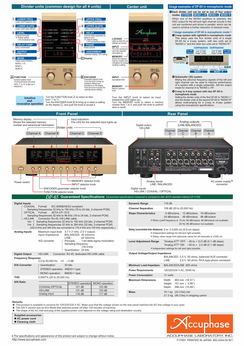
❶ 2-way system with right/left in monophonic mode This setup uses the four divider units of a single
DF-65 for a 2-way system, with two units set to "MONO L" and the other two units set to "MONO R".
❷ Subwoofer (3D) system Mixing the ultra-low frequency signals of the left and
right channel can be used to improve performance of a system with a single subwoofer. Set the output mode for channel A to "MONO L+R".
❸ 2-way to 4-way system with two DF-65 in monophonic mode
Setting the divider units of the first DF-65 to "MONO L" and the divider units of the second DF-65 to "MONO R" allows multi-amping for a 2-way to 4-way system using the monophonic specifications.
Cutoff frequenciesFor left channel
For right channel
Lowrange
Preamplifier
Highrange
Cutoff frequencies
Lowrange
Highrange
DF-65 Channel A
MONO LChannel B Channel D
MONO RChannel C
L
R
Digital Inputs COAXIAL Format: IEC 60958/AES3 compliant Sampling frequencies 32 kHz to 192 kHz (16 to 24 bits, 2-channel PCM) OPTICAL Format: JEITA CP-1212 Sampling frequencies 32 kHz to 96 kHz (16 to 24 bits, 2-channel PCM) HS-LINK Connector: RJ-45, HS-LINK cable Ver. 1 Sampling frequencies 32 kHz to 192 kHz (24 bits, 2-channel PCM) Ver. 2 Sampling frequencies 32 kHz to 384 kHz (32 bits, 2-channel PCM) (352.8 kHz and 384 kHz are converted to 176.4 kHz and 192 kHz respectively.)Analog Inputs Maximum input level 3.7 V (1 kHz, 2.5 V output) Input impedance BALANCED: 40 kilohms LINE: 20 kilohms A/D converter Principle: 1-bit delta sigma modulation Sampling frequency: 176.4 kHz Quantization: 24 bitsDigital Output HS-LINK Connector: RJ-45, dedicated HS-LINK cableFrequency Response 2.0 to 50,000 Hz +0 –3 dBD/A Converter Quantization: 32 bits STEREO operation: 4MDS++ type MONO operation: 8MDS++ typeTHD 0.0007% (20 to 20,000 Hz)
S/N Ratio
Dynamic Range 118 dB
Channel Separation 108 dB (20 to 20,000 Hz)
Slope Characteristics 6 dB/octave, 12 dB/octave, 18 dB/octave 24 dB/octave, 48 dB/octave, 96 dB/octave *When cutoff frequency is 10 Hz: 48 dB/octave, 96 dB/octave not available 20 Hz: 96 dB/octave not available
Delay (converted into distance) 0 to ±3,000 cm (0.5-cm steps) * Independent settings for left and right possible. * Delay value range limit (absolute value) for all channels is 3,000 cm.
Level Adjustment Range "Analog ATT" OFF: –40 to + 12.0 dB (0.1-dB steps) "Analog ATT" ON: –50 to + 2.0 dB (0.1-dB steps) *Independent settings for left and right possible.
Output Voltage/Output Impedance BALANCED: 2.5 V, 50 ohms, balanced XLR connector LINE: 2.5 V, 50 ohms, RCA-type phono connector
Minimum Load Impedanc BALANCED/LINE 600 ohms
Power Requirements 120/220/230 V AC, 50/60 Hz
Power Consumption 31 watts
Maximum Dimensions Width 465 mm (18.31˝) Height 151 mm (15.95˝) Depth 396 mm (15.59˝)
Mass 15.1 kg (33.3 lbs) net 21.0 kg (46.3 lbs) in shipping carton
● High-speed DSP realizes fully digital signal processing in channel divider units ● Standard configuration allows 4-channel (4-way) system setup ● 59 selectable cutoff frequency points ● Highly accurate 96 dB/oct attenuation slope ● Time alignment function allows delay time setting in 0.5-cm steps ● Delay compensator offsets signal delays in filter circuitry ● Further refined MDS++ D/A converter● Selectable monophonic output mode for further enhanced specifications
Rear PanelFront Panel
Divider units (common design for all 4 units) Center unit
Intuitiveand
innovative operation
Display
UPPER FREQUpper cutoff frequency (Hz)
UPPER SLOPEUpper cutoff slope (dB/oct)
DELAYChannel delay expressed as distance (cm)* Default setting: L=R simultaneous mode PHASEPhase selector
ASSIGNMENTCharacter display, OFF setting
LOWER FREQLower cutoff frequency (Hz)
LOWER SLOPELower cutoff slope (dB/oct)
LEVELChannel level (dB)* Default setting: L=R simultaneous mode
MODEOutput mode STEREO,MONO L+R,MONO L,MONO R
OUTPUTOutput ON/OFF
DELAY COMPDelay compensator
<Usage examples of DF-65 in monophonic mode>
Usage examples of DF-65 in monophonic mode
Guaranteed Specifications [Guaranteed specifications measured in compliance with JEITA standard method CP-2150]
Turn the INPUT knob to select an input (respective LED lights up).Turn the MEMORY knob to select a memory number from 1 to 5, and push the knob to perform save or recall.
Turn the FUNCTION knob A to select an item from ① to ⑪.Turn the ENCODER knob B to bring up a value or setting on the display C, and push the knob to accept it.
ENCODERParameter selector knob(Turn the knob to bring up available settings and indications on the display. Push the knob to accept the currently shown setting.)
FUNCTIONFunction selector knob(Turning the knob will cause LEDs ① to ⑩ to light up in sequence.)
■Each divider unit can be set to one of four output modes: STEREO , MONO L+R , MONO L , MONO R When one of the MONO positions is selected, the DAC output for the left and right channel circuits in the unit are combined and driven in parallel, which can be used to achieve a further reduction of residual noise.
※特色:マゼンダはDIC-160 シアンは指定色で
F1705Y PRINTED IN JAPAN 850-2204-00(B1)5年間保証
Remarks This product is available in versions for 120/220/230 V AC. Make sure that the voltage shown on the rear panel matches the AC line voltage in your area.
The 230 V version has an Eco Mode that switches power off after 120 minutes of inactivity. The shape of the AC inlet and plug of the supplied power cord depends on the voltage rating and destination country.
● The specifications and appearance of this product are subject to change without notice.
★★★
Supplied accessories● AC power cord● Cleaning cloth

High-speed 40-bit floating point DSP
Assembly with high-speed DSP chip
DF-65 Block Diagram
Block Diagram of MDS++ Converter
Time Alignment Principle
Assembly with HS-LINK digital input and output connectors, line input connectors, MDS++ D/A converters for 4 channels, line output connectors etc.
Thick aluminum top plate with elegant hairline finish
AnalogAttenuator
ON/OFF
AnalogAttenuator
ON/OFF
OpticalReceiver
MonoON/OFF
A/DConverter
HS-LINKTransmitter
CoaxialReceiver
HS-LINKReceiver
Display
Line
Balanced
DigitalInputs
AnalogInputs
LeftAnalogOutputs
RightAnalogOutputs
Line
Balanced
Digital Filter
Frequency
Master Level
Level
Phase Slope
Delay Delay Comp
Output
DSP
Floating Point
DSP: Digital Signal Processor
DAIDecoder
Date/ClockDistributor
Micro-ComputerEncoder
DigitalOutput
Channel A
Channel D
Channel C
Channel B Same as Channel A
Same as Channel A
Same as Channel A
Balanced
HS-LINK
Line
Coaxial
HS-LINK
Optical
MDS++D/A Conversion System × 4
MDS++ D/A Conversion System × 4
DAC
Digital Filter
DAC
CoefficientMemory
Buffer
Buffer
Buffer
Buffer
<Operation principle of delay compensator>
t2
Input
When OFF, ⓐ is slowest, delayed by t2 seconds versus ⓑ
Using the slowest ⓐ as reference (0), ⓑ is delayed
ⓑ is delayed by t2 seconds
[Delayed by t2 seconds when ON]
(Low-pass filter)
[Channel A]
[Channel B]
(High-pass filter)
Delay: t2 s
Delay: 0 s
0
t2
(ⓐ compensationtime)
(ⓑ compensationtime)ON/OFF
ON/OFF
DELAY COMP function ON
DELAY COMPfunction
Time lag (delay) ofoutput signal with regard to input in each channel
When DELAY COMP is OFF, the output signals in each channel will be time-shifted due to the delay.
Output ⓐ
Output ⓑ
When OFF When ON
WhenON/OFF
Actual delay compensator indication is in cm, converted from the above compensation time value.
When passing through the different filter circuits, the signals will be delayed by a certain amount as compared to the input.
When DELAY COMP is ON, the time difference between output signals ⓐ and ⓑ is eliminated.
[Channel A]
[Channel B]
t seconds
t secondsd cm
Input
L
Delay
DelayTime
Start time
Delay function delays Ⓗ waveform by t seconds
H H
L
⇨
<Time alignment using delay>
DAC 1
DAC 2
DAC 3
DAC 4
DACoutput
Subtraction
(Normal phaseoutput)
(Reverse phaseoutput)
Currentsumming
Voltagesumming
I (current) / V (voltage) converter
I-V
I-V
I-V
I-V
-
+
Function Display indicationLOWER FREQUENCY
LOWER SLOPE
LEVEL
DELAY COMP
OUTPUT
MODE
UPPER FREQUENCY
UPPER SLOPE
PHASE
ASSIGNMENT
Default settings of each unit
● ( ) symbol at top right of level indication is shown when "Full Level Output Protection" function is set to ON.
Factory default: L=R simultaneous mode
Factory default: L=R simultaneous modeDELAY
Delay ensures that Ⓛ and Ⓗ signals arrive at the ear at the same time
Sound sources (diaphragms) of speaker units Ⓛ and Ⓗ are d centimeters apart
Divider unit slope characteristics (bandpass filter)(Cutoff frequency setting 100 Hz for lower and 1 kHz for upper range)
[dBr]
[Hz]Frequency
6 dB/oct 6 dB/oct
12 dB/oct 12 dB/oct
18 dB
/oct 18 dB/oct
24 d
B/oc
t 24 dB/oct
48 d
B/oc
t 48 dB/oct
96 d
B/oc
t 96 dB/oct
PASSPASS
10 20 30 50 70 100 200 500 1k 2k 3k 5k 7k 10k−100
−90
−80
−70
−60
–50
−40
−30
−20
−10
0
Built-in cutoff frequencies (Hz)Cutoff characteristics: –3.0 dB, 59 points
Innovative Technology
The Digital Frequency Dividing Network DF-65 harnesses the very best of digital technology in every aspect, including a high-speed 40-bit floating point DSP. The standard unit configuration supports signal processing for up to four-way systems. Highly accurate digital filters offer a choice of 59 cutoff frequency points and up to 96 dB/octave attenuation. Integrated time alignment function adjustable in 0.5-cm steps, and delay compensator for automatically offsetting any filter circuit delays. Monophonic output mode provides high versatility for various configurations.
Advanced Features
■ High-speed, high-precision DSP implements fully digital signal processing Designed to serve as the core component of a multi-amped system, the
channel divider DF-65 features high-speed digital signal processing with amazing power. Latest digital circuit topology and advanced technology come together in a floating-point DSP that has a 32-bit mantissa and 8-bit exponent section, serving as digital filter. The division into mantissa and exponent prevents errors even when handling very small values.
This results in dramatically improved dynamic range and superior precision, allowing very steep cutoff slope settings of 48 dB or 96 dB per octave. All other functions including phase, delay, and level control are also implemented in the digital domain. The result is ultra-precise filtering free from adverse effects by temperature changes or aging.
■ 59 selectable cutoff frequency points Filter frequency points can be set over the range from 31.5 Hz to 22.4 kHz in 1/6-octave
intervals. In addition, 10, 20, and 290 Hz points are also provided, resulting in a total of 59 points. Each divider unit is fully flexible and allows independent selection of lower and upper cutoff frequency.
■ Six filter slope characteristics with up to 96 dB attenuation per octave The filter attenuation characteristics can be set to 6 dB, 12 dB, 18 dB, 24 dB, 48 dB, or 96 dB
per octave. The 96 dB/octave setting in particular allows the driver unit to reproduce only its intended frequency without being affected by adjacent frequency bands. This makes it possible to create a multi-amped system that takes musical accuracy to a wholly new level.
10 20 31.5 35.5 40 45 50 56 63 71 80 90 100 112 125 140 160 180 200 224 250 280 290 315 355 400 500 560 630 710 800 900 1000 1120 1250 1400 1600 1800 2000 2240 2500 2800 3150 3550 4000 5000 5600 6300 7100 8000 9000 10k 11.2k 12.5k 14k 16k 18k 20k 22.4k
Multi-channel divider with fully digital signal processing realizes the ultimate in audio enjoyment with outstanding performance, sophisti-cated features and intuitive operation
■ High-performance HyperstreamTM DAC used for MDS++
MDS (Multiple Delta Sigma) is a revolutionary design that employs multiple delta-sig-ma type D/A converters connected in parallel, for drastically improved perfor-mance. In the DF-65, four HyperstreamTM DAC chips (ES9018S made by ESS Technology) of the latest generation are driven in parallel. Compared to a single converter, this results in an overall performance improvement by a factor of 2 (= √4).
■ Time alignment function allows delay adjustment in 0.5-cm steps
The DF-65 incorporates a DELAY function that uses digital signal processing to electrically adjust the time when the sound from each driver reaches the listener. Normally, a delay would be expressed as a time value, but since the delay here is caused by spatial distance, the DF-65 converts it into a distance value (cm) for display.
■ Digital attenuator with setting range from –40.0 dB to +12.0 dB (in 0.1dB steps) allows precise level adjustments for left and right channels.
■ "Analog ATT" function can be activated for specific channels to reduce residual noise when using high-efficiency speaker units (ON: –10 dB).
■ Versatile choice of input connectors:Coaxial, optical, and /HS-LINK for digital signalsLine and balanced for analog signals
■ "Full Level Output Protection" function safeguards the speakers if a digital signal without volume control data is input (Output level is reduced to –40 dB).
■ Unused divider units can be set to OFF (all display elements and LED indicators are out).
■ Independent phase switching for left and right channel (4 patterns).
Left/Right: Normal phaseLeft/Right: Inverted phaseLeft: Normal phase, Right: Inverted phaseLeft: Inverted phase, Right: Normal phase
■ Memory feature allows saving and recalling function settings.
■ System backup function allows returning the entire system to a previous condition.
■ Safety Lock prevents inadvertently changing any settings.
■ Display indication can show predefined strings or custom strings entered by the user (max. 8 charac-ters, character set 97 characters).
■ Elegant side panels with natural wood grain finish
When a signal passes a filter circuit, a delay necessarily occurs. The "DELAY COMP" function compensates for such delays. The illustration at left uses a 2-way system as an example to show how the delay compensator works.■ Regardless of whether a circuit is analog or
digital, when the signal has to pass through a filter, the output will be delayed by a certain amount, causing a delay in step response and impulse response.
■ Generally, a low-pass filter will have more delay. The DF-65 therefore only provides compensation when low-pass filtering is used.
■ The lower the filter frequency and the steeper the filter slope, the longer the delay.
Delay compensator function of DF-65 (providing automatic compensation for signal delays)
OFF :The DF-65 calculates and displays the theoretical delay time for reference, and the user can manually set any desired value.
:The DF-65 calculates and displays the theoretical delay time, and automatically provides compensation. (Default setting)
ON
ReferenceSpeed of sound = 331.5 + 0.607 T [m/sec] T: temperature (°C)
Consequently, at 20°C, sound travels at about 343.5 m/sec.
In the example above, when the DELAY function for Ⓗ is set to d cm, the signal start for Ⓗ will be delayed by t = d/34,350 seconds, causing the sound from Ⓛ and Ⓗ to reach the listener at the same time.
LOCKEDLights up when the unit settings are locked.
INPUTThe LED correspond-ing to the selected input lights up.
MEMORYShows the selected memory number and indications for saving/recalling a setting.
INPUTInput selector knob
MEMORYMemory selectorknob
Analog outputs(LINE/BALANCED)
Channel A Channel B Channel C Channel DChannel
DChannel
CChannel
BChannel
A
Power switch
ENCODER parameter selector knobFUNCTION selector knob
MEMORY selector knobINPUT selector knob
Memory displayShows the selected memory number and save/recall information
Input indicatorsThe LED for the selected input lights up
Digital inputs HS-LINK / COAXIAL / OPTICAL
Digital output HS-LINK
Analog inputs LINE / BALANCED
AC power supply ★connector
Divider units
STEREO operation121 dB121 dB116 dB
MONO operation123 dB123 dB117 dB
COAXIAL/OPTICALHS-LINKAnalog Input
❶ 2-way system with right/left in monophonic mode This setup uses the four divider units of a single
DF-65 for a 2-way system, with two units set to "MONO L" and the other two units set to "MONO R".
❷ Subwoofer (3D) system Mixing the ultra-low frequency signals of the left and
right channel can be used to improve performance of a system with a single subwoofer. Set the output mode for channel A to "MONO L+R".
❸ 2-way to 4-way system with two DF-65 in monophonic mode
Setting the divider units of the first DF-65 to "MONO L" and the divider units of the second DF-65 to "MONO R" allows multi-amping for a 2-way to 4-way system using the monophonic specifications.
Cutoff frequenciesFor left channel
For right channel
Lowrange
Preamplifier
Highrange
Cutoff frequencies
Lowrange
Highrange
DF-65 Channel A
MONO LChannel B Channel D
MONO RChannel C
L
R
Digital Inputs COAXIAL Format: IEC 60958/AES3 compliant Sampling frequencies 32 kHz to 192 kHz (16 to 24 bits, 2-channel PCM) OPTICAL Format: JEITA CP-1212 Sampling frequencies 32 kHz to 96 kHz (16 to 24 bits, 2-channel PCM) HS-LINK Connector: RJ-45, HS-LINK cable Ver. 1 Sampling frequencies 32 kHz to 192 kHz (24 bits, 2-channel PCM) Ver. 2 Sampling frequencies 32 kHz to 384 kHz (32 bits, 2-channel PCM) (352.8 kHz and 384 kHz are converted to 176.4 kHz and 192 kHz respectively.)Analog Inputs Maximum input level 3.7 V (1 kHz, 2.5 V output) Input impedance BALANCED: 40 kilohms LINE: 20 kilohms A/D converter Principle: 1-bit delta sigma modulation Sampling frequency: 176.4 kHz Quantization: 24 bitsDigital Output HS-LINK Connector: RJ-45, dedicated HS-LINK cableFrequency Response 2.0 to 50,000 Hz +0 –3 dBD/A Converter Quantization: 32 bits STEREO operation: 4MDS++ type MONO operation: 8MDS++ typeTHD 0.0007% (20 to 20,000 Hz)
S/N Ratio
Dynamic Range 118 dB
Channel Separation 108 dB (20 to 20,000 Hz)
Slope Characteristics 6 dB/octave, 12 dB/octave, 18 dB/octave 24 dB/octave, 48 dB/octave, 96 dB/octave *When cutoff frequency is 10 Hz: 48 dB/octave, 96 dB/octave not available 20 Hz: 96 dB/octave not available
Delay (converted into distance) 0 to ±3,000 cm (0.5-cm steps) * Independent settings for left and right possible. * Delay value range limit (absolute value) for all channels is 3,000 cm.
Level Adjustment Range "Analog ATT" OFF: –40 to + 12.0 dB (0.1-dB steps) "Analog ATT" ON: –50 to + 2.0 dB (0.1-dB steps) *Independent settings for left and right possible.
Output Voltage/Output Impedance BALANCED: 2.5 V, 50 ohms, balanced XLR connector LINE: 2.5 V, 50 ohms, RCA-type phono connector
Minimum Load Impedanc BALANCED/LINE 600 ohms
Power Requirements 120/220/230 V AC, 50/60 Hz
Power Consumption 31 watts
Maximum Dimensions Width 465 mm (18.31˝) Height 151 mm (15.95˝) Depth 396 mm (15.59˝)
Mass 15.1 kg (33.3 lbs) net 21.0 kg (46.3 lbs) in shipping carton
● High-speed DSP realizes fully digital signal processing in channel divider units ● Standard configuration allows 4-channel (4-way) system setup ● 59 selectable cutoff frequency points ● Highly accurate 96 dB/oct attenuation slope ● Time alignment function allows delay time setting in 0.5-cm steps ● Delay compensator offsets signal delays in filter circuitry ● Further refined MDS++ D/A converter● Selectable monophonic output mode for further enhanced specifications
Rear PanelFront Panel
Divider units (common design for all 4 units) Center unit
Intuitiveand
innovative operation
Display
UPPER FREQUpper cutoff frequency (Hz)
UPPER SLOPEUpper cutoff slope (dB/oct)
DELAYChannel delay expressed as distance (cm)* Default setting: L=R simultaneous mode PHASEPhase selector
ASSIGNMENTCharacter display, OFF setting
LOWER FREQLower cutoff frequency (Hz)
LOWER SLOPELower cutoff slope (dB/oct)
LEVELChannel level (dB)* Default setting: L=R simultaneous mode
MODEOutput mode STEREO,MONO L+R,MONO L,MONO R
OUTPUTOutput ON/OFF
DELAY COMPDelay compensator
<Usage examples of DF-65 in monophonic mode>
Usage examples of DF-65 in monophonic mode
Guaranteed Specifications [Guaranteed specifications measured in compliance with JEITA standard method CP-2150]
Turn the INPUT knob to select an input (respective LED lights up).Turn the MEMORY knob to select a memory number from 1 to 5, and push the knob to perform save or recall.
Turn the FUNCTION knob A to select an item from ① to ⑪.Turn the ENCODER knob B to bring up a value or setting on the display C, and push the knob to accept it.
ENCODERParameter selector knob(Turn the knob to bring up available settings and indications on the display. Push the knob to accept the currently shown setting.)
FUNCTIONFunction selector knob(Turning the knob will cause LEDs ① to ⑩ to light up in sequence.)
■Each divider unit can be set to one of four output modes: STEREO , MONO L+R , MONO L , MONO R When one of the MONO positions is selected, the DAC output for the left and right channel circuits in the unit are combined and driven in parallel, which can be used to achieve a further reduction of residual noise.
※特色:マゼンダはDIC-160 シアンは指定色で
F1705Y PRINTED IN JAPAN 850-2204-00(B1)5年間保証
Remarks This product is available in versions for 120/220/230 V AC. Make sure that the voltage shown on the rear panel matches the AC line voltage in your area.
The 230 V version has an Eco Mode that switches power off after 120 minutes of inactivity. The shape of the AC inlet and plug of the supplied power cord depends on the voltage rating and destination country.
● The specifications and appearance of this product are subject to change without notice.
★★★
Supplied accessories● AC power cord● Cleaning cloth