modernization design criteria for rural state trunk ... · fdm 11-15 attachment 1.2 modernization...
TRANSCRIPT

FDM 11-15 Attachment 1.1 Modernization Design Criteria for Rural State Trunk Highways Functionally Classified as Arterials
November 30, 2018 Attachment 1.1 Page 1
Modernization Design Criteria for Rural State Trunk Highways Functionally Classified as Arterials (Level Terrain)
Traffic Volume Roadway Width Dimensions Bridges
Design Class
Design AADT
Design Speed (mph)
Traveled Way Width
(feet)
Shoulder Width (feet)
Roadway Width (feet)2
Minimum Design Loading
Clear Roadway Width of Bridges (feet)2, 3
A1 Under 3500 60 24 6 36 5 36
A21
(2 lanes)
3,500–8,700A
3,500–15,000C 60 24 8-10 40-44 5 40-44
A31
(4 lane divided)
8,700A - 44,000A
8,700B - 53,500B
15,000C - 60,000C
704 2 at 24
4-6LT
10RT6
2 at 38-40
5 2 at 40
A31
(6 lane divided)
44,000A - 69,000A
53,500B - 85,000B
60,000C - 90,000C
704 2 at 36 10 LT and RT7 2 at 56 5 2 at 56
A For Non-freeway Corridors 2020 Backbone and Connector Routes, LOS threshold is C/D or 4.0. B For Freeway Corridors 2020 Backbone Route, LOS threshold is C/D or 4.0. C For other Principal and Minor Arterials, LOS threshold is D/E or 5.0. 1 The top of the traffic volume range for design class A2 is 8,700 AADT for a Corridors 2020 Routes and 15,000 AADT for Non-corridors 2020 routes. These volumes are based on
the 2000 Highway Capacity Manual assuming; level terrain, 12-foot lanes, ≥ 6-foot shoulders, 80% passing, 10% trucks, K30 design factor, and 60/40 directional split. In cases where reduced levels of service are determined to be acceptable and the uses of passing lanes are found to be adequate treatment for the facilities, the 8,700 AADT value for C2020 Connector Routes may be increased to 12,000 AADT. Design class A3 assumptions: level terrain, 12-foot lanes > 6-foot shoulders, 10% trucks, K30 design factor, 61/39 directional split, 2 access points per mile, except freeway. See FDM 11-5-3 for additional information on level of service thresholds for different facility types and the respective numerical values.
2 Normally provide full widths of approach roadways across all new bridges. Justifications may be made when the bridges are considered major structures on which design dimensions are subject to individual economic studies because of high unit costs. See FDM 11-26-30.5.13.3 for Roadway Widths, Clear Roadway Widths of Bridges, and Underpasses between Closely Spaced Roundabouts.
3 Lateral clearance design criteria for underpass bridges are included in FDM 11-35-1. 4 See FDM 11-10-1. 5 See WisDOT Bridge Manual and consult with Bureau of Structures for appropriate Bridge Design Loading. 6 Use 12 foot paved shoulders (right) on 4-lane freeways if truck traffic >250 DHV, or if the facilities experience a high degree of congestion and incidents. The roadway widths and
clear roadway widths on bridges are increased accordingly. 7 Use 12 foot paved shoulders (left & right) on 6-lane freeways if truck traffic > 250 DHV or if the facilities experience high degrees of congestion and incidents. The roadway widths
and clear roadway widths on bridges are increased accordingly.

FDM 11-15 Attachment 1.1 Modernization Design Criteria for Rural State Trunk Highways Functionally Classified as Arterials
November 30, 2018 Attachment 1.1 Page 2
Modernization Design Criteria for Rural State Trunk Highways Functionally Classified as Arterials (Rolling Terrain)
Traffic Volume Roadway Width Dimensions Bridges3,4
Design Class Design ADT
Design Speed (mph)2
Traveled Way width Based On Design Speed (feet)
Shoulder Width (feet)
Roadway Width Based On Design Speed (feet)3
Design Loading
Bridge Clear
Roadway Width (feet)
55 mph or less
60 mph or greater
55 mph or less
60 mph or greater
A1 0-1500 50-60 22-24 24 6 34-36 36 5 36
1500-3500 24 24 6 36 36 5 36
A21
(2 lanes)
3,500-8,700A
3,500-15,000C 50-60 24 24 8-10 40-44 40-44 5 40-44
A31,B
(4 lane divided)
8,700 - 40,000A
15,000 - 55,000C 60-706 2 at 24
4-6 LT
10 RT7 2 at 38-40 5 2 at 40
A31,B
(6 lane divided)
40,000 – 63,000A
55,000 - 82,000C 60-70 2 at 36 10 LT & RT8 2 at 56 5 2 at 56
A For Non-freeway Corridors 2020 Backbone and Connector Routes, LOS threshold is C/D or 4.0. B Level terrain standards apply to Freeway Corridors 2020 Backbone Routes, LOS threshold is C/D or 4.0. C For other Principal and Minor Arterials, LOS threshold is D/E or 5.0. 1 The top of the traffic volume range for design class A2 is 8,700 AADT for a Corridors 2020 Route (LOS threshold of 4.0) and 15,000 AADT for Non-corridors 2020 Route (LOS
threshold of 5.0). These volumes are based on the 2000 Highway Capacity Manual assuming; rolling terrain, 12-foot lanes, ≥ 6-foot shoulders, 80% passing, 10% trucks, K30 design factor, and 60/40 directional split. In cases where reduced levels of service are determined to be acceptable and the use of passing lanes are found to be adequate treatments for the facilities, the 8,700 AADT value for C2020 Connector Routes may be increased to12,000 AADT. Design class A3 assumptions: rolling terrain, 12-foot lanes, >6-foot shoulders, 10% trucks, K30 design factor, 61/39 directional split, 2 access points per mile, except Freeway. See FDM 11-5-3 for additional information on level of service thresholds for different facility types and the respective numerical values.
2 Design Speeds should typically be 5 mph greater than the posted speeds. Lower design speeds equal to the posted speed limits are acceptable if justified in the SCD or DSR DJ. 3 Normally provide full widths of approach roadways across all new bridges. Justifications may be made when the bridges are considered major structures on which design
dimensions are subject to individual economic studies because of high unit costs. See FDM 11-26-30.5.13.3 for Roadway Widths, Clear Roadway Widths of Bridges, and Underpasses between Closely Spaced Roundabouts.
4 Lateral clearance design criteria for underpass bridges are included in FDM 11-35-1. 5 See WisDOT Bridge Manual and consult with Bureau of Structures for appropriate Bridge Design Loadings. 6 See FDM 11-10-1. 7 Use 12-foot paved shoulders (right) on 4-lane freeways if truck traffic >250 DHV, or if the facilities experience high degrees of congestion and incidents. The roadway widths and
clear roadway widths on bridges are increased accordingly. 8 Use 12-foot paved shoulders (left and right) on 6-lane freeways if truck traffic > 250 DHV or if the facilities experience high degrees of congestion and incidents. The roadway
widths and clear roadway widths on bridges are increased accordingly.

FDM 11-15 Attachment 1.2 Modernization Design Criteria for Rural State Trunk Highways Functionally Classified as Collectors
November 30, 2018 Attachment 1.2 Page 1
Modernization Design Criteria for Rural State Trunk Highways Functionally Classified as Collectors (Level Terrain)
Traffic Volume Roadway Width Dimensions 1,6 Bridges 3,4
Design Class
Current ADT Design ADT
Design Speed (mph)2
Traveled Way Width Based On Design
Speed (feet) Shoulder
Width (feet)
Roadway Width3 Based On Design Speed (feet)
Min. Design Loading
Clear Roadway Width of Bridges
50 mph or less
55 mph or greater
50 mph or less
55 mph or greater
C1 0 - 400 40-60 20-24 22-24 2-4 24-32 26-32 5 26-30
C2 401 - 750 Under 1500 50-60 22-24 22-24 5-6 32-36 32-36 5 28-30
C3 1500-2000 50-60 22-24 24 6 34-36 36 5 32-34
2000-3500 60 24 6 36 5 36
C4 Over 3500 60 24 8 40 5 40
1 Where ranges of widths are shown, the smaller numbers are the lower range of the widths and the larger numbers are the upper range of the widths eligible for federal or state project participation.
2 Design Speeds should typically be 5 mph greater than the posted speeds. Lower design speeds equal to the posted speed limits are acceptable if justified in the SCD or DSR DJ.
3 Bridges in Design Classes C3 and C4 with total lengths over 100 feet may be designed with a clear roadway withs of 30 feet. See FDM 11-26-30.5.13.3 for Roadway Widths, Clear Roadway Widths of Bridges, and Underpasses between Closely Spaced Roundabouts.
4 Lateral clearance design criteria for roadways under bridges are included in FDM 11-35-1. 5 See WisDOT Bridge Manual and consult with Bureau of Structures for appropriate Bridge Design Loadings. 6 Lane widths shall be 12 feet on Federally Designated Long Truck Routes (i.e. the "National Network" as defined in 23 CFR Part 658).

FDM 11-15 Attachment 1.2 Modernization Design Criteria for Rural State Trunk Highways Functionally Classified as Collectors
November 30, 2018 Attachment 1.2 Page 2
Modernization Design Criteria for Rural State Trunk Highways Functionally Classified as Collectors (Rolling Terrain)
Traffic Volume Roadway Width Dimensions1,6 Bridges3,4
Design Class
Current ADT Design ADT
Design Speed (mph)2
Traveled Way Width Based on Design Speed
(feet) Shoulder
Width (feet)
Roadway Width 3 Based on Design Speed (feet)
Design Loading
Clear Roadway Width of Bridges
50 mph or less
55 mph or greater
50 mph or less
55 mph or greater
C1 0-400 30-60 20-24 22-24 2-4 24-28 26-28 5 26-30
C2 401-750 Under 1500 40-60 22-24 22-24 5-6 32-36 32-36 5 28-30
C3 1500-2000 40-60 22-24 24 6 34-36 36 5 32-34
2000-3500 50-60 24 24 6 36 36 5 36
C4 Over 3500 50-60 24 24 8 40 40 5 40
1 Where ranges of widths are shown, the smaller numbers are the lower range of the widths and the larger numbers are the upper range of the widths eligible for
federal or state project participation. 2 Design Speeds should typically be 5 mph greater than the posted speeds. Lower design speeds equal to the posted speed limits are acceptable if justified in the
SCD or DSR DJ. 3 Bridges in Design Classes C3 and C4 with total lengths over 100 feet may be designed with clear roadway widths of 30 feet. Bridges in Design Classes C3 and
C4 with total lengths over 100 feet may be designed with clear roadway widths of 30 feet. See FDM 11-26-30.5.13.3 for Roadway Widths, Clear Roadway Widths of Bridges, and Underpasses between Closely Spaced Roundabouts.
4 Lateral clearance design criteria for roadways under bridges are included in FDM 11-35-1. 5 See WisDOT Bridge Manual and consult with Bureau of Structures for appropriate Bridge Design Loadings. 6 Lane widths shall be 12 feet on Federally Designated Long Truck Routes (i.e. the "National Network" as defined in 23 CFR Part 658).

FDM 11-15 Attachment 1.3 Modernization Design Criteria for Rural State Trunk Highways Functionally Classified as Local Roads
November 30, 2018 Attachment 1.3 Page 1
Modernization Design Criteria for Rural State Trunk Highways Functionally Classified As Local Roads (Level Terrain)
Traffic Volume Roadway width Dimensions 1 Bridges 1,3,4
Design Class
Current ADT Design ADT
Design Speed (mph) 2
Traveled Way Width Based on Design Speed
(feet) Shoulder
Width (feet)
Roadway Width 3, Based on Design Speed (feet)
Design Load
Clear Roadway Width of Bridges Based on Design Speed (feet)
40 mph or less
45-50 mph
55 mph or more
40 mph or less
45-50 mph
55 mph or more
50 mph or less
55 mph or more
L1 0-250 30-60 18-22 20-22 22 2-4 22-26 24-26 26 5 24-28 26-28
L2 250-400 40-60 18-22 20-22 22 2-4 22-30 24-30 26-30 5 26-30 26-30
L3 400-750 Under 1500 50-60 22-24 22-24 5-6 32-36 32-36 5 28-30 28-30
L4 1500-2000 50-60
22-24 24 6 34-36 36 5 30-34 30-34
2000-3500 24 24 6 36 36 5 36 36
L5 Over 3500 50-60 24 24 8 40 5 40 40
1 Where ranges of widths are shown, the lower numbers are the lower range of widths and the larger are the upper range of widths eligible for federal or state
project participation. 2 Design Speeds should typically be 5 mph greater than the posted speeds. Lower design speeds equal to the posted speed limits are acceptable if justified
in the SCD or DSR DJ. 3 Bridges in Design Classes L4 and L5 with total lengths over 100 feet may be designed with clear roadway widths of 30 feet. See FDM 11-26-30.5.13.3 for
Roadway Widths, Clear Roadway Widths of Bridges, and Underpasses between Closely Spaced Roundabouts. 4 Lateral clearance design criteria for underpass bridges are included in FDM 11-35-1. 5 See WisDOT Bridge Manual and consult with Bureau of Structures for appropriate Bridge Design Loadings.

FDM 11-15 Attachment 1.3 Modernization Design Criteria for Rural State Trunk Highways Functionally Classified as Local Roads
November 30, 2018 Attachment 1.3 Page 2
Modernization Design Criteria for Rural State Trunk Highways Functionally Classified As Local Roads (Rolling Terrain)
Traffic Volume Roadway width Dimensions 1 Bridges 1,3,4
Design Class
Current ADT Design ADT
Design Speed (mph) 2
Traveled Way Width Based On Design Speed (feet)
Shoulder Width (feet)
Roadway Width 3, Based On Design Speed (feet)
Design Load
Clear Roadway Width of Bridges Based on
Design Speed (feet)
40 mph or less
45-50 mph
55 mph or more
40 mph or less
45-50 mph
55 mph or more
50 mph or less
55 mph or more
L1 0-250 30-60 18-22 20-22 22 2-4 22-26 24-26 26 5 24-28 26-28
L2 250-400 40-60 18-22 20-22 22 2-4 22-26 24-26 26 5 26-30 26-30
L3 400-750 Under 1500 40-60 20-24 22-24 22-24 5-6 30-36 32-36 32-36 5 28-30 28-30
L4 1500-2000 40-60
22-24 22-24 24 6 34-36 34-36 36 5 30-34 30-34
2000-3500 24 24 24 6 36 36 36 5 36 36
L5 Over 3500 40-60 24 24 24 8 40 40 40 5 40 40
1 Where ranges of widths are shown, the lower numbers are the lower range of widths and the larger are the upper range of widths eligible for federal or state project participation.
2 Design Speeds should typically be 5 mph greater than the posted speeds. Lower design speeds equal to the posted speed limits are acceptable if justified in the SCD or DSR DJ.
3 Bridges in Design Classes L4 and L5 with total lengths over 100 feet may be designed with clear roadway widths of 30 feet. See FDM 11-26-30.5.13.3 for Roadway Widths, Clear Roadway Widths of Bridges, and Underpasses between Closely Spaced Roundabouts.
4 Lateral clearance design criteria for underpass bridges are included in FDM 11-35-1. 5 See WisDOT Bridge Manual and consult with Bureau of Structures for appropriate Bridge Design Loadings.
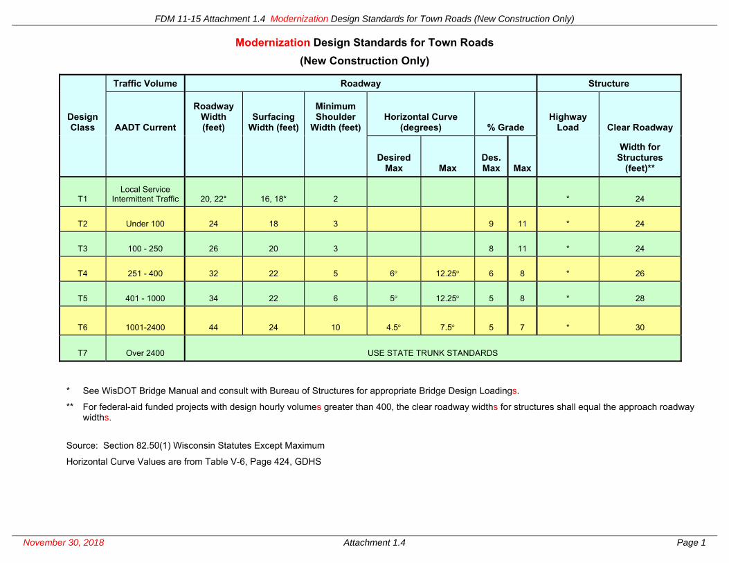
FDM 11-15 Attachment 1.4 Modernization Design Standards for Town Roads (New Construction Only)
November 30, 2018 Attachment 1.4 Page 1
Modernization Design Standards for Town Roads (New Construction Only)
Traffic Volume Roadway Structure
Design Class AADT Current
Roadway Width (feet)
Surfacing Width (feet)
Minimum Shoulder
Width (feet) Horizontal Curve
(degrees) % Grade Highway
Load Clear Roadway
Desired
Max Max Des. Max Max
Width for Structures
(feet)**
T1 Local Service
Intermittent Traffic 20, 22* 16, 18* 2 * 24
T2 Under 100 24 18 3 9 11 * 24
T3 100 - 250 26 20 3 8 11 * 24
T4 251 - 400 32 22 5 6 12.25 6 8 * 26
T5 401 - 1000 34 22 6 5 12.25 5 8 * 28
T6 1001-2400 44 24 10 4.5 7.5 5 7 * 30
T7 Over 2400 USE STATE TRUNK STANDARDS
* See WisDOT Bridge Manual and consult with Bureau of Structures for appropriate Bridge Design Loadings.
** For federal-aid funded projects with design hourly volumes greater than 400, the clear roadway widths for structures shall equal the approach roadway widths.
Source: Section 82.50(1) Wisconsin Statutes Except Maximum
Horizontal Curve Values are from Table V-6, Page 424, GDHS

FDM 11-15 Attachment 1.4 Modernization Design Standards for Town Roads (New Construction Only)
November 30, 2018 Attachment 1.4 Page 2
Modernization Design Criteria for Reconstruction* of Town Roads1
TRAFFIC
DESIGN SPEED2
(MPH)
ROADWAY WIDTH DIMENSIONS
Design Class Current AADT Traveled Way Width
(feet) Shoulder Width (feet) Roadway Width (feet)
RT1 0 - 250
40 or less 18-20 2-3 22-26
45-50 20 2-3 24-26
55 or greater 22 2-3 26-28
RT2
251 - 400
40 or less 18-22 2-4 22-30
45-50 20-22 2-4 24-30
55 or greater 22 2-4 26-30
401 - 750 (50) 22 6 34
55 or greater 22 6 34
RT3 Over 750 50 or less 22-24 6 34-36
55 or greater 24 6 36
* Note: Reconstruction means total rebuilding of existing town roads to improve maintainability, safety, geometrics and traffic service. Design criteria for construction of new town roads are shown on page 1 of this attachment. To avoid confusion in the terminology used to label design classes for the two design criteria, the design classes for town road “Reconstruction” begin with the letter “R”.
1 Source: TRANS 204, Existing Town Road Criteria. 2 Design Speeds should typically be 5 mph greater than the posted speeds. Lower design speeds equal to the posted speed limits are acceptable.

FDM 11-15 Attachment 1.5 Rural State Trunk Highway Modernization Paved Shoulder Width Criteria
November 30, 2018 Attachment 1.5 Page 1
RURAL STATE TRUNK HIGHWAY MODERNIZATION PAVED SHOULDER WIDTH CRITERIA 1
DESIGN CLASS
PAVED SHOULDER WIDTHS
(reconstruction, new construction, or pavement replacement projects)
A1
3 feet on concrete roadways
5 feet on asphalt roadways
C3, L4
3 feet on concrete roadways
5 feet on asphalt roadways
A2
3 feet on concrete roadways
5 feet on asphalt roadways
C4, L5
3 feet on concrete roadways
5 feet on asphalt roadways
A3 4 - LANE DIVIDED
EXPRESSWAY
R2 - 8 feet
L - 3 feet
A3 6 - LANE DIVIDED
EXPRESSWAY
R - 8 feet
L - 8 feet
A3 4 - LANE INTERSTATE
OR FREEWAY
R3 - 10 feet
L - 4 feet
A3 6 - LANE INTERSTATE
OR FREEWAY
R4 - 10 feet
L4 - 10 feet
A3 1 - LANE RAMPS
R - 5 feet
L - 3 feet
1 See FDM 11-15-5 for shoulder width criteria for projects on the Great River Road. See FDM 11-46-15 for shoulder criteria to accommodate bicycles.
2 These shoulder widths also apply to initial two-lane roadways of ultimate four-lane highways except when construction of the second roadways are not expected for at least six years. In these cases, initially pave only 3 feet right along concrete roadways and 5 feet right along asphaltic roadways.
3 Use 12-foot paved shoulders (right) on 4-lane freeways if truck traffic >250 DHV, or if the facilities experience high degrees of congestion and incidents. The roadway widths and clear roadway widths on bridges are increased accordingly.
4 Use 12-foot paved shoulders (left and right) on 6-lane freeways if truck traffic > 250 DHV or if the facilities experience high degrees of congestion and incidents. The roadway widths and clear roadway widths on bridges are increased accordingly.

FDM 11-15 Attachment 1.6 Typical Modernization Cross Sections for Rural 2-Lane Highways
November 30, 2018 Attachment 1.6 Page 1

FDM 11-15 Attachment 1.6 Typical Modernization Cross Sections for Rural 2-Lane Highways
November 30, 2018 Attachment 1.6 Page 2
NOTES: 1. Pavement structure elements vary depending on the pavement designs.
2. If special ditch grades or greater ditch capacities are necessary for longitudinal drainage then vary the widths or side slopes (not steeper than upper values) of the ditches.
3. Use combinations of flat slopes and rounding to blend earth cut back slopes into the natural topography. The designs of cut-to-fill transitions also require special attention to ensure gradually steepened slopes in order to produce a natural and aesthetically pleasing cross sections.
4. Subgrade slopes are parallel to pavement structures.
5. See FDM 11-15-1.7 for guidance on subgrade widths and locating subgrade shoulder points.
6. See FDM 11-15 Attachments 1.9, 1.10 or 1.11 for clear zone distances.
7. See FDM 11-15 Attachment 1.1, 1.2, 1.3, 1.4, 1.15, 1.16 and 1.17 for traveled way widths and roadway width requirements.
8. See FDM 11-15-1.4 for guidance on shoulders. See FDM 11-15 Attachments 1.1, 1.2, 1.3, 1.4, 1.15, 1.16 and 1.17 for total shoulder width requirements. See FDM 11-15-1.4.2 and FDM 11-15 Attachment 1.5 for policy and requirements on paved shoulders.
See FDM 11-15-1.4 for guidance on shoulder cross slopes - including conditional use of 2% on asphaltic and concrete shoulders.
9. See FDM 11-5-15 for guidance on subgrade improvement layers. WisDOT policy requires using select materials in the upper portions of subgrades developed from soils that are difficult for subgrade construction. Drain these select materials with relief trenches at all sag points and at intervals between sag points.
10. Provide additional roadway widening for barrier systems. See other sections of the FDM for guidance.

FDM 11-15 Attachment 1.7 Typical Modernization Cross Sections for Divided Highways and 1-Lane Ramps
November 30, 2018 Attachment 1.7 Page 1
NOTES: 1. Pavement structure elements vary depending on the pavement designs.
2. If special ditch grades or greater ditch capacities are necessary for longitudinal drainage then vary the widths or side slopes (not steeper than upper values) of the ditches.
3. Use combinations of flat slopes and rounding to blend earth cut back slopes into the natural topography. The design of cut-to-fill transitions also requires

FDM 11-15 Attachment 1.7 Typical Modernization Cross Sections for Divided Highways and 1-Lane Ramps
November 30, 2018 Attachment 1.7 Page 2
special attention to ensure gradually steepened slopes in order produce a natural and aesthetically pleasing cross section.
4. Subgrade slopes are parallel to pavement structures.
5. See FDM 11-15-1.7 for guidance on subgrade widths and locating subgrade shoulder points.
6. See FDM 11-15 Attachments 1.9, 1.10 or 1.11 for clear zone distances.
7. See FDM 11-15, Attachments 1.1, and 1.15, for traveled way widths and roadway width requirements for Design Class A3.
8. See FDM 11-15-1.4 for guidance on shoulders. See FDM 11-15, Attachments 1.1, and 1.15, for total shoulder width requirements for Design Class A3. See FDM 11-15-1.4.2 and FDM 11-15 Attachment 1.5 for policy and requirements on paved shoulders.
See FDM 11-15-1.4 for guidance on shoulder cross slopes – including conditional use of 2% on asphaltic and concrete shoulders.
If the mainline pavement structures are PC concrete then 2 foot monolithic shoulders are required on the right (i.e., outside) shoulder (excluding ramps).
9. See FDM 11-5-15 for guidance on subgrade improvement layers. WisDOT policy requires using select materials in the upper portions of subgrades developed from soils that are difficult for subgrade construction. Drain these select materials with relief trenches and/or special trenching with pipe underdrain systems at all sag points and at intervals between sag points.
10. See FDM 11-5-15 for guidance on subgrade improvement layers, including their lateral drainage. Use of subgrade layers are at the discretion of the designers in consultation with the region soils engineer.
11. Provide additional roadway widening for barrier systems. See other sections of the FDM for guidance.
12. The median widths shall be 60 ft. on expressways with posted speeds greater than 55 mph. Do not steepen side slopes to achieve lesser ditch depths below subgrade shoulders.

FDM 11-15 Attachment 1.8 Modernization Roadway Sections in Rock Cut
November 30, 2018 Attachment 1.8 Page 1
ROADWAY SECTION IN ROCK CUT
ALTERNATE DITCH SECTION IN ROCK CUT
NOTES: 1. When rock cuts are less than 15’, backslopes should generally be treated the same as backslopes in earth
cuts. When rock cuts are 15’ or more, slopes should be as steep as practical for the particular types of rock on the projects. A commonly used standard slope for rock cuts is 1/2:1. Consult with district soils engineer when determining roadway cross sections in rock cuts.
2. Alternate ditch sections may be used when warranted on the basis of cost/benefit analyses. 3. Traffic barriers should be used to shield the ditches. Steel plate beam guard may be used as alternatives to
the concrete shoulder barriers. Removable barrier sections should be provided at approximately 200’ intervals for maintenance access to the ditches.

FDM 11-15 Attachment 1.9 Modernization Clear Zone Distance Tables and Recovery Area Width Determination
November 30, 2018 Attachment 1.9 Page 1
Modernization Clear Zone Distance Table (in Feet from Edge of Traveled Way) Ref. (2) Table 3.1, pages 3-6
(U.S. Customary Units)
Design
Speed
Design
ADT
Foreslopes Backslopes
IV:6H
or flatter
IV:5H To
IV:4H IV:3H IV:3H
IV:5H To
IV:4H
IV:6H
or flatter
40 mph
or
less
Under 750
750-1500
1500-6000
Over 6000
7-10
10-12
12-14
14-16
7-10
12-14
14-16
16-18
**
**
**
**
7-10
10-12
12-14
14-16
7-10
10-12
12-14
14-16
7-10
10-12
12-14
14-16
45-50
mph
Under 750
750-1500
1500-6000
Over 6000
10-12
12-14
16-18
18-20
12-14
16-20
20-26
24-28
**
**
**
**
8-10
10-12
12-14
14-16
8-10
12-14
14-16
18-20
10-12
14-16
16-18
20-22
55 mph Under 750
750-1500
1500-6000
Over 6000
12-14
16-18
20-22
22-24
14-18
20-24
24-30
26-32*
**
**
**
**
8-10
10-12
14-16
16-18
10-12
14-16
16-18
20-22
10-12
16-18
20-22
22-24
60 mph Under 750
750-1500
1500-6000
Over 6000
16-18
20-24
26-30
30-32*
20-24
26-32*
32-40*
36-44*
**
**
**
**
10-12
12-14
14-18
20-22
12-14
16-18
18-22
24-26
14-16
20-22
24-26
26-28
65-70
mph
Under 750
750-1500
1500-6000
Over 6000
18-20
24-26
28-32*
30-34*
20-26
28-36*
34-42*
38-46*
**
**
**
**
10-12
12-16
16-20
22-24
14-16
18-20
22-24
26-30
14-16
20-22
26-28
28-30
* Clear zone widths greater than 30 feet as indicated are desirable for new construction and major reconstruction and where site-specific investigations indicates high probabilities of continuing crashes or where such occurrences are indicated by crash history. Clear zones may be limited to 30 feet for practicality and to provide consistent roadway templates if previous experiences with similar projects or designs indicates satisfactory performance and if justified by the SCDs or DSR DJs. ** Since recovery is less likely on unshielded, traversable 3:1 slopes, fixed objects should not be present in the vicinity of the toes of these slopes. Recoveries of high-speed vehicles that encroach beyond the edges of shoulders may be expected to occur beyond the toes of slopes. The method for determining the widths of recovery are described on page 2 of this Attachment.

FDM 11-15 Attachment 1.9 Modernization Clear Zone Distance Tables and Recovery Area Width Determination
November 30, 2018 Attachment 1.9 Page 2
* The clear runout area is additional clear-zone space that is needed because a portion of the required clear zone (shade area) falls on a non-recoverable slope. These configurations are not desirable because of the difficulty of maintaining the clear runout areas. Provide the entire required clear zone widths adjacent to finished shoulders, if at all possible. The widths of the clear runout areas are equal to those portions of the clear zone distances that are located in the non-recoverable slopes, or 10 feet, whichever is greater.
The clear runout areas may be reduced in width based on existing conditions or site investigations. Such variable sloped typical sections are often used as compromises between roadside safety and economics. By providing relatively flat recovery areas immediately adjacent to the roadways, most errant motorists can recover before reaching the steeper slopes beyond. Round the slope break points liberally so encroaching vehicles do not become airborne. Make the steeper slopes as smooth as practical and rounded at the bottoms.

FDM 11-15 Attachment 1.10 Modernization Horizontal Curve Correction Factors
November 30, 2018 Attachment 1.10 Page 1
Kcz (Curve Correction Factors) Ref. (2) Table 3.2, Page 3-7
Radius (ft)
Design Speed (mph)
40 45 50 55 60 65 70
2860 1.1 1.1 1.1 1.2 1.2 1.2 1.3
2290 1.1 1.1 1.2 1.2 1.2 1.3 1.3
1910 1.1 1.2 1.2 1.2 1.3 1.3 1.4
1640 1.1 1.2 1.2 1.3 1.3 1.4 1.5
1430 1.2 1.2 1.3 1.3 1.4 1.4 ---
1270 1.2 1.2 1.3 1.3 1.4 1.5 ---
1150 1.2 1.2 1.3 1.4 1.5 --- ---
950 1.2 1.3 1.4 1.5 1.5 --- ---
820 1.3 1.3 1.4 1.5 --- --- ---
720 1.3 1.4 1.5 --- --- --- ---
640 1.3 1.4 1.5 --- --- --- ---
570 1.4 1.5 --- --- --- --- ---
380 1.5 --- --- --- --- --- ---
Note:
The clear zone correction factors are applied to the outsides of curves only. Curves flatter than 2860 feet do not require adjusted clear zones.
CZc = (Lc) (Kcz)
Where: CZc = clear zone on outside of curvature,
Lc = clear zone tangent section,
Kcz = curve correction factor

FDM 11-15 Attachment 1.11 Modernization Ditch Traverseability Evaluation Charts
February 7, 2003 Attachment 1.11 Page 1
Ref. (2) Figure 3.6, Page 3-11

FDM 11-15 Attachment 1.11 Modernization Ditch Traverseability Evaluation Charts
February 7, 2003 Attachment 1.11 Page 2
Ref. (2) Figure 3.7, Page 3-12
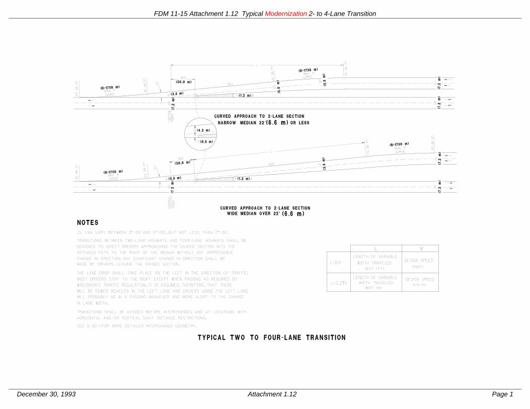
FDM 11-15 Attachment 1.12 Typical Modernization 2- to 4-Lane Transition
December 30, 1993 Attachment 1.12 Page 1

FDM 11-15 Attachment 1.13 Typical Modernization Marsh Sections
December 30, 1993 Attachment 1.13 Page 1

FDM 11-15 Attachment 1.14 Lateral Clearance on Modernization Rural Roadways
February 7, 2003 Attachment 1.14 Page 1
Lateral Clearance on Modernization Rural Roadways
REQUIRED LATERAL CLEARANCE
Finished Shoulder EDG
E O
F D
RIV
ING
LAN
E
WITHOUT ROADSIDE BARRIER
REQUIRED LATERAL CLEARANCE
EDG
E O
F D
RIV
ING
LAN
E
WITH ROADSIDE BARRIER
REQUIRED LATERAL CLEARANCE
Finished Shoulder EDG
E O
F D
RIV
ING
LAN
E
WITHOUT ROADSIDE BARRIER
REQUIRED LATERAL CLEARANCE
EDG
E O
F D
RIV
ING
LAN
E
WITH ROADSIDE BARRIER

FDM 11-15 Attachment 1.15 Modernization Design Criteria for County Trunk Highways Functionally Classified as Arterials
November 30, 2018 Attachment 1.15 Page 1
Modernization Design Criteria for County Trunk Highway Functionally Classified as Arterials
TRAFFIC VOLUME ROADWAY BRIDGES2
Design Class
Design AADT
Design Speed
Traveled Way Width
Shoulder Width
Roadway Width
Minimum Design Loading
Clear Roadway Width of Bridges3
A1 Under 3500 60 mph 4 24’ 6’ 36’ 5 36’
A21 3500-15000 60 mph 24’ 10’ 44’ 5 44’
A3 Over 15000 70 mph 6 24’ (2) 6’ L
10’ R 40’ (2) 5 40’
1 The top of the traffic volume range for design class A2 is 15,000 AADT (LOS trigger of 5.0.) The volume is based on the 2000 Highway Capacity Manual assuming; level terrain, 12-foot lanes, > 6-foot shoulders, 80 percent passing, 10 percent trucks, K30 design factor, and directional split of 60/40. See FDM 11-5-3 for additional information on threshold triggers, levels of service for different facility types and the respective numerical values.
2 The full widths of approach roadways should normally be provided across all new bridges. Design Justifications may be made when bridges are considered major structures on which design dimensions should be subject to individual economic studies because of the high unit costs.
3 Lateral clearance design criteria for underpass bridges are included in FDM 11-35-1. 4 For County Highways in design class A1 the design speeds should typically be 60 mph; however, lower
design speeds of 55 mph are acceptable if justified by a safety analysis and documented in the DSR as a Design Justification (DJ).
5 See WisDOT Bridge Manual and consult with Bureau of Structures for appropriate Bridge Design Loadings. 6 See discussion in FDM 11-10-1.
Source: For County Trunk Highway Standards see TRANS 205.

FDM 11-15 Attachment 1.16 Modernization Design Criteria for County Trunk Highways Functionally Classified as Collectors
November 30, 2018 Attachment 1.16 Page 1
Modernization Design Criteria for County Trunk Highways Functionally Classified as Collectors
TRAFFIC VOLUME ROADWAY1 WIDTH DIMENSIONS BRIDGES1,4
Design Class
Current ADT
Design ADT
Design Speed
Traveled Way Shoulder Roadway
Minimum Design Loading
Clear Roadway Width of Bridges
C1 0-400 40 MPH 22’-24’ 2’-4’ 26’-32’ 5 26’-30’
C2 400-750 Under 1500 50 MPH 22’-24’ 6’ 34’-36’ 5 28’-30’
C3 1500-3500 60 MPH3 24’ 6’ 36’ 5 32’-34’ 2
C4 Over 3500 60 MPH 24’ 8’ 40’ 5 40’ 2
1 Where ranges of widths are shown, the smaller numbers are the lower range of widths and the larger
numbers are the upper range of widths eligible for federal or state project participation. 2 Bridges in Design Classes C3 and C4 with total lengths over 100 feet may be designed with clear roadway
widths of 30 feet. 3 For County Trunk Highways in design class C3, a design speed of 55 mph are acceptable. 4 Lateral clearance design criteria for roadways under bridges are included in FDM 11-35-1. 5 See WisDOT Bridge Manual and consult with Bureau of Structures for appropriate Bridge Design Loadings.
Source: Administrative Rule Trans 205, “County Trunk Highway Standards”

FDM 11-15 Attachment 1.17 Modernization Design Criteria for County Trunk Highways Functionally Classified as Local Roads
November 30, 2018 Attachment 1.17 Page 1
Modernization Design Criteria for County Trunk Highways Functionally Classified as Local Roads
TRAFFIC VOLUME ROADWAY1 WIDTH DIMENSIONS BRIDGES1,4
Design Class
Current ADT
Design ADT
Design Speed
Traveled Way Shoulder Roadway
Minimum Design
Loading
Clear Roadway Width of Bridges
L1 0-250 40 MPH 20’-22’ 2’-4’ 24’-30’ 5 24’-28’
L2 250-400 40 MPH 22’ 2’-4’ 26’-30’ 5 26’-30’
L3 400-750 Under 1500 50 MPH 22’-24’ 6’ 34’-36’ 5 28’-30’
L4 1500-3500 602 MPH 24’ 6’ 36’ 5 30’-34’ 3
L5 Over 3500 60 MPH 24’ 8’ 40’ 5 40’ 3
1 Where ranges of widths are shown, the smaller numbers are the lower range of widths and the larger
numbers are the upper range of widths eligible for federal or state project participation. 2 For County Trunk Highways in design class L4, a design speeds of 55 mph are acceptable. 3 Bridges in Design Classes L4 and L5 with total lengths over 100 feet may be designed with clear roadway
widths of 30 feet. 4 Lateral clearance design criteria for underpass bridges are included in FDM 11-35-1. 5 See WisDOT Bridge Manual and consult with Bureau of Structures for appropriate Bridge Design Loadings.
Source: Administrative Rule Trans 205, “County Trunk Highway Standards”

FDM 11-15 Attachment 1.18 Modernization Design Criteria for Interstate Highways
November 30, 2018 Attachment 1.18 Page 1
Modernization Design Criteria for Interstate Highways
Number of Travel Lanes (Total Both Directions) 4-Lane 6-Lane or More
Sideslopes 4:1 or flatter (Recoverable) or 3:1 maximum (Traversable) with Recovery Area meeting FDM 11-15 Attachment 1.9
Traffic Lanes
Widths 12 feet 12 feet
Cross Slope 2% 2%
Superelevation 6%maximum 6% maximum
Shoulders Widths 10 feet Right1 / 4 feet Left 10 feet Right and Left 2
Cross Slope 4% 4%
New and Replacement Bridges
Vertical Clearance 16 feet minimum. See FDM 11-35 Attachment 1.8
Roadway Width3 Full Approach Roadway Width except Major Long Span Structures shall provide 4-foot minimum from edge of traffic lanes to parapets3
Design Loading Structural Capacity4 HL-93 (HS-20) minimum 4 HL-93 (HS-20) minimum4
Bridges to Remain in Place
Lane Widths (Feet) 12 feet 12 feet
Shoulder Widths (Feet)
10 feet Right / 3.5 feet Left minimum except 3.5 feet Left and Right minimum for Major Long Span
Structures
10 feet Right and Left minimum except 3.5 feet Left and Right minimum for
Major Long Span Structures
Lateral Clearance5 See FDM 11-15 Table 1.2 5
Roadside Design
Curb or Curb and Gutter Barrier curbs shall not be used. Mountable curbs, when used, should be located at the outer edge of the shoulder. Also, where guardrail is used, the face of the
curb should be flush with the face of guardrail or behind it.
Clear Zone Widths and Fixed Objects
FDM 11-15 Attachment 1.9 and the AASHTO Roadside Design Guide should be used for guidance regarding warranted clear zone widths. Fixed Objects within
the clear zone should be removed, made breakaway or made safe through shielding by a roadside barrier and/or crash cushion.
Median Inlets and Ditch Checks
Median inlets should have 6:1 or flatter traversable grates and 10:1 or flatter ditch checks.
Median and Maintenance Crossovers
Median/Maintenance Crossovers should be eliminated whenever possible, or constructed to have 10:1 or flatter side slopes.
Construction Crossovers
Removed after project completion unless they are planned to be used for future maintenance or other traffic control operations. Construction crossovers left-in-place should 10:1 or flatter side slopes and appropriate safety devices installed
along their length to minimize the potential for median-crossing crashes and unauthorized U-turns.
Traffic Control Devices/Signing Shall be in conformance with the current Manual on Uniform Traffic Control
Devices (MUTCD) and the Wisconsin Manual on Uniform Traffic Control Devices (WMUTCD).
Access Control Right-of-way fencing or other appropriate measures shall be incorporated into all
Interstate projects to address any access control issues within the proposed project limits.
Notes: 1 Use 12 foot paved shoulders (right) on 4-lane freeways if truck traffic >250 DHV, or if the facilities experience a high
degree of congestion and incidents. The roadway widths and clear roadway widths on bridges are increased accordingly.

FDM 11-15 Attachment 1.18 Modernization Design Criteria for Interstate Highways
November 30, 2018 Attachment 1.18 Page 2
2 Use 12 foot paved shoulders (left and right) on 6-lane freeways if truck traffic > 250 DHV or if the facilities experience high degrees of congestion and incidents. The roadway widths and clear roadway widths on bridges are increased accordingly.
3 Normally provide full widths of approach roadways across all new bridges. Justifications may be made when the bridges are considered major structures on which design dimensions are subject to individual economic studies because of high unit costs.
4 See WisDOT Bridge Manual and consult with Bureau of Structures for appropriate Bridge Design Loading. 5 Lateral clearance design criteria for underpass bridges are included in FDM 11-35-1.

FDM 11-15 Attachment 5.1 Great River Road Map
February 28, 2001 Attachment 5.1 Page 1

FDM 11-15 Attachment 5.1 Great River Road Map
February 28, 2001 Attachment 5.1 Page 2
Great River Road – Legal Definition 84.107 Great River Road. (1) The department shall designate and mark as the “Great River Road” the route in Grant, Crawford, Vernon, La Crosse, Trempealeau, Buffalo, Pepin and Pierce counties commencing at the Wisconsin–Illinois border and proceeding northerly on STH 35 to its junction with STH 133; then proceeding westerly on STH 133 to its junction with CTH “VV” near Cassville; then proceeding northerly on CTH “VV” to its junction with CTH “A”; then proceeding westerly on CTH “A” to its junction with CTH “X” in Bagley; then proceeding northerly on CTH “X” to its junction with CTH “C”; then proceeding easterly on CTH “C” to its junction with STH 35, with all of the preceding highways in Grant County; then proceeding northerly on STH 35 to its junction with USH 14/61 in La Crosse County; then proceeding northerly on USH 14/61 to its junction with USH 53; then proceeding northerly on USH 53 to its junction with STH 35; then proceeding northerly on STH 35 to its junction with Business 35/CTH “HD” near Holmen; then proceeding northerly on Business 35/CTH “HD” to its junction with STH 35; then proceeding northerly on STH 35 to its junction with USH 10 in Pierce County; and then proceeding westerly on USH 10 to the Wisconsin–Minnesota border. (2) If the department, after investigations and studies, finds that any proposed Great River Road development is advantageous to the state, it shall have full authority to perform, on behalf of the state, each and every duty required of the state, in order to secure and complete the proposed development project. For the purposes of such development projects, the Great River Road shall be a portion of the state trunk highway system. History: 1993 a. 357.

FDM 11-15 Attachment 10.1 Rural STH Passing Lane Corridors
February 28, 2001 Attachment 10.1 Page 1

FDM 11-15 Attachment 10.2 Warrant for Considering Passing Lanes
March 13, 2000 Attachment 10.2 Page 1
Warrant for Considering Passing Lanes
Note: The Rolling Terrain criterion should be considered only for projects located in western and southwest Wisconsin. See the text of this procedure for additional warranting criteria.
Source: Washington State DOT