models bb, sd, hip, and ap “specific application ... · the tyco ® model bb ... tyco® model...
TRANSCRIPT

GeneralDescriptionThe Tyco® Peak™ Performance Mod-els BB™ (Back to Back), SD™ (SingleDirectional), HIP™, and AP™ (AtticPlus) “Specific Application Sprinklersfor Protecting Attics” are fire sprinklersfor combustible and non-combustiblesloped attic spaces. The Model BB,SD, and HIP are Specific ApplicationAttic Sprinklers, whereas the ModelAP is a Specific Application Combusti-ble Concealed Space Sprinkler havingspecific application criteria for its usewith the Model BB, SD, and HIP in atticspaces. Specific Application AtticSprinklers provide superior fire protec-tion in attic spaces and, when com-pared to Standard Spray Sprinklers,cost savings are achieved by eliminat-ing branchline materials and the asso-ciated installation labor. “The SpecificApplication Sprinklers for ProtectingAttics” have undergone the most ex-tensive fire testing ever performed forsloped attic spaces. They are ULListed with their specific applicationguidelines for use as special sprinklersas defined by the NFPA.
The Specific Application Attic Sprin-klers provide an extended coveragespacing alternative to the restrictedspacing of Standard Spray Sprinklers.The restricted spacings of StandardSpray Sprinklers used within attics isdescribed in the 2007 edition of NFPA
13, Table 8.6.2.2.1(a) and Section8.6.4.1.4.
The Specific Application Attic Sprin-klers are the first sprinklers to be:
• Listed for extended coverage incombustible construction.
• Full-scale fire tested in both wet anddry system scenarios.
• Full-scale fire tested, for use in woodtruss construction.
• Listed for specific roof slopes (Referto Table A).
The Specific Application Attic Sprin-klers provide the best level of protec-tion and control cost by eliminating theneed for additional sprinklers andbranchline piping. In many cases, anattic can be entirely protected with justone line of piping located below thepeak of the roof using Model BB (Backto Back) Sprinklers. If there is a needfor Model SD (Single Directional) orModel HIP Sprinklers, one line ofeither of these sprinkler types is usu-ally sufficient at each area being cov-ered. For example and assuming theuse of Standard Spray Sprinklers, asystem in a 60 foot (18,3 m) wide attic,with up to a 12:12 roof pitch, designedto the 2007 edition of NFPA 13, wouldrequire seven branchlines to cover themain portion of the attic and severaladditional branchlines to cover the hipareas. With the Specific ApplicationAttic Sprinklers, the required coveragecan be obtained with just one branch-line below the peak and one downeach slope of the hip beam. This wouldresult in approximately 90% less pipeneeded for installation. This reductionin the number of branchlines saves thecost of the pipe, fittings, hangers, andassociated labor by eliminating up tofive branchlines.
Another important aspect of the Spe-cific Application Attic Sprinkler tech-nology is the reduction in system vol-ume. This volume reduction may resultin reducing the size of a dry pipe valve(and air compressor) and possibly al-
Page 1 of 28 TFP610MAY, 2008
Models BB, SD, HIP, and AP“Specific Application Sprinklersfor Protecting Attics”
Technical Services: Tel: (800) 381-9312 / Fax: (800) 791-5500
IMPORTANTAlways refer to Technical DataSheet TFP700 for the “INSTALLERWARNING” that provides cautionswith respect to handling and instal-lation of sprinkler systems and com-ponents. Improper handling and in-stallation can permanently damagea sprinkler system or its compo-nents and cause the sprinkler to failto operate in a fire situation or causeit to operate prematurely.

Page 2 of 28 TFP610
FIGURE BMODEL BB1, BB2 & BB3
WITH 5.6 K-FACTORSPECIFIC APPLICATION ATTIC
SPRINKLERS
FIGURE CMODEL BB1, BB2 & BB3
WITH 4.2 K-FACTORSPECIFIC APPLICATION ATTIC
SPRINKLERS
FIGURE DMODEL SD1, SD2 & SD3
WITH 5.6 K-FACTORSPECIFIC APPLICATION ATTIC
SPRINKLERS
10
SECTION
7
Assembly
-
-
---
-
-
-
Compression Deflector
Assembly
DiffuserLink
Rivet
FrameDeflector
Saddle
ScrewLever
4
3
6
5
Components:
-
--
Sealing
BodyCap
8
FLOW
(63,5 mm)2-1/2"
CROSS
2 1
SIDEELEVATION
11(28,6 mm)
(57,2 mm)1-1/8"
2-1/4"
FLOW
NPT1/2"
HEXWRENCH
FRAMEARMS
(39,7 mm)1-9/16"
9
NOMINAL MAKE-IN7/16" (11,1 mm)
1
4
23
5
76
8
109
11
FRAME54
FRONTCROSSSECTION ELEVATION
ARMS
(11,1 mm)
MAKE-INNOMINAL
37/16"
RELIEFTHREAD
2-1/8"(54,0 mm)
1 2
FLATSWRENCH
1/2" NPT
Compression5 --2 Button
Deflector
(20,6 mm)6 13/16"1-1/8"
FLOW FLOW
(28,6 mm)
(57.2 mm)2-1/4"
SealingAssembly
-36 -
Screw
(41,3 mm)1-5/8"
Components:
Frame-1 4 Bulb-
ELEVATION
7
4
3
6
5
10
2 1
SIDE
WRENCHHEX
(76,2 mm)3"
1-5/16"(33,4 mm)
FLOW
2-1/8"(54,0 mm)
1/2" NPT
FRAMEARMS
1-5/16"(33,3 mm)
9
8
SECTIONCROSS MAKE-IN
7/16"(11,1 mm)NOMINAL
- Saddle
CapBody
Sealing
Components:
Assembly
-
-- Rivet
Link
Deflector
AssemblyFrame
Compression-ScrewLeverDeflector
--
---
4
23
1
7
5
69
10
8
FIGURE AMODEL BB1, BB2 & BB3
WITH 8.0 K-FACTORSPECIFIC APPLICATION ATTIC
SPRINKLERS
(12,7 mm)
2-1/4"(57.2 mm)
FrameButtonSealing
Deflector
BulbCompression
AssemblyScrew
5 -
6 -3 -
4 -21
--
FLOW
3
4
(28,6 mm)1-1/8"
2-1/8"(54,0 mm)
FLOW
5
2
FRONTELEVATION
1/2"
13/16"(20,6 mm)
6
(41,3 mm)1-5/8"
FLATS
3/4" NPT
WRENCH
SECTIONCROSS
RELIEFTHREAD
1ARMS
FRAME
NOMINALMAKE-IN
Components:
low for quicker water delivery times,eliminating the need for an accelera-tor.
The other cost reduction is the Listingof BlazeMaster* CPVC for use in atticspaces to supply the wet system “Spe-cific Application Sprinklers for Protect-ing Attics”, as well as the wet systemsprinklers below the ceiling. Tradition-ally BlazeMaster CPVC has been usedon the lower floors in the joist spaceabove a ceiling that does not requiresprinklers. The savings of using CPVCon those floors can now be translatedto the upper floor even if sprinklers arerequired in the attic.
There are four (4) models of the “Spe-cific Application Sprinklers for Protect-ing Attics” — BB™ (Back to Back DualDirectional), SD™ (Single Direc-tional), HIP™, and AP™ (Attic Plus).The BB and SD Sprinklers have threeseparate versions that are used fordifferent roof pitches. The pitches, asapplicable, can vary from a minimumof 3:12 to a maximum of 12:12 (Ref.Table A).
BB Sprinkler (Back to BackDual Directional)The Tyco® Model BB™ Specific Appli-cation Attic Sprinkler (Figure A, B & C)throws a narrow but long pattern. The
narrow spacing along the ridge servestwo purposes. The response time isreduced by placing the sprinklers nofarther than 6 feet (1,8 m) apart, andthe spray can be concentrated in thethrow direction to obtain a pattern thatwill cover up to 30 feet (9,1m) in eachdirection when measured horizontally.There are three different models (i.e.,BB1, BB2 & BB3) that account for dif-ferent roof slopes, and each model isavailable in one of three different ori-fice sizes (K=4.2, 5.6, or 8.0).
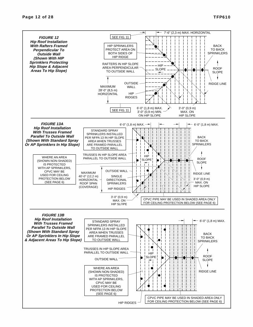
SD Sprinkler (Single Directional)The Tyco® Model SD™ Specific Appli-cation Attic Sprinkler (Figure D), likethe Model BB, throws a narrow butlong pattern. However, unlike theModel BB the Model SD only dis-charges in one direction. These sprin-klers are primarily used where shearwalls or draft curtains have been in-stalled within an attic space. Anotheruse is when the framing direction isparallel with the outside wall in the hiparea (Ref. Figure 13). In this case, theSD would be used on one side of theslope, and AP Sprinklers or StandardSpray Sprinklers would be used to pro-tect the other side. The Model SDSprinklers must be installed in a verti-cal upright orientation and not angledwith the slope. (Achieving the vertical
upright orientation may require the useof a swing joint if the SD Sprinklers arebeing supplied from a line runningalong and parallel to the roof hip.)Three different models (i.e., SD1,SD2 & SD3) are available for differentroof slopes.
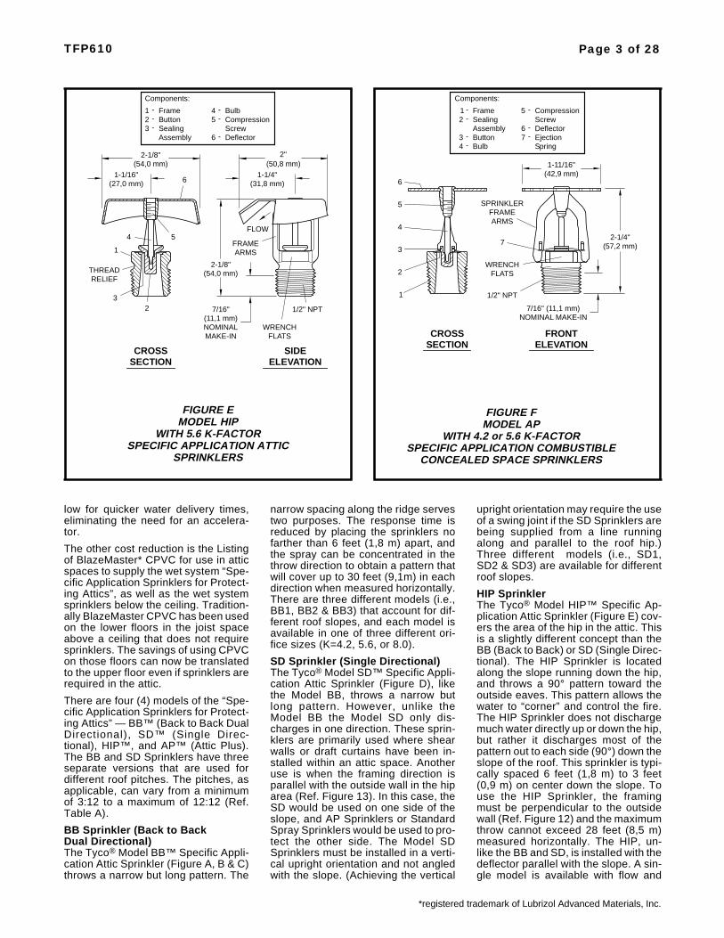
HIP SprinklerThe Tyco® Model HIP™ Specific Ap-plication Attic Sprinkler (Figure E) cov-ers the area of the hip in the attic. Thisis a slightly different concept than theBB (Back to Back) or SD (Single Direc-tional). The HIP Sprinkler is locatedalong the slope running down the hip,and throws a 90° pattern toward theoutside eaves. This pattern allows thewater to “corner” and control the fire.The HIP Sprinkler does not dischargemuch water directly up or down the hip,but rather it discharges most of thepattern out to each side (90°) down theslope of the roof. This sprinkler is typi-cally spaced 6 feet (1,8 m) to 3 feet(0,9 m) on center down the slope. Touse the HIP Sprinkler, the framingmust be perpendicular to the outsidewall (Ref. Figure 12) and the maximumthrow cannot exceed 28 feet (8,5 m)measured horizontally. The HIP, un-like the BB and SD, is installed with thedeflector parallel with the slope. A sin-gle model is available with flow and
TFP610 Page 3 of 28
FIGURE FMODEL AP
WITH 4.2 or 5.6 K-FACTORSPECIFIC APPLICATION COMBUSTIBLE
CONCEALED SPACE SPRINKLERS
FIGURE EMODEL HIP
WITH 5.6 K-FACTORSPECIFIC APPLICATION ATTIC
SPRINKLERS
(54,0 mm)2-1/8"
SIDEELEVATION
FLOW
6 (31,8 mm)
2"(50,8 mm)
1-1/4"
FRAMEARMS
(54,0 mm)2-1/8"
1-1/16"(27,0 mm)
4 5
SECTIONCROSS
(11,1 mm)
MAKE-INNOMINAL
7/16" 1/2" NPT
WRENCHFLATS
THREAD
1
RELIEF
32
Assembly
FrameButtonSealing
Components:
1 -23
--
-4-5
-6
BulbCompression
DeflectorScrew
CROSSSECTION
2
1
3
4
5
6
FRAME
FLATSWRENCH
ARMS
FRONTELEVATION
7/16" (11,1 mm)NOMINAL MAKE-IN
SPRINKLER
(42,9 mm)1-11/16"
2-1/4"(57,2 mm)
1/2" NPT
7
Sealing
-Deflector-
SpringEjection
Assembly
Bulb--
CompressionScrew
Components:
Frame--
-
Button4
2
3
1
76
5
*registered trademark of Lubrizol Advanced Materials, Inc.

pressure requirements for two differ-ent spacings.
AP Sprinkler (Attic Plus)Installed in the upright orientation withtheir deflector parallel to the roof, theTyco® Model AP™ Sprinklers (FigureF) are intended to be used to provideprotection of attic areas outside thescope of application for the BB, SD, orHIP Sprinklers. When used, the APSprinklers in most cases will provide ahydraulic advantage over StandardSpray Sprinklers for the protection ofattic areas outside the scope of appli-cation for the BB, SD, or HIP Sprin-klers (Ref. Figures 21 and 22 for exam-ples).
WARNINGThe “Specific Application Sprinklersfor Protecting Attics” described hereinmust be installed and maintained incompliance with this document, aswell as with the applicable standardsof the National Fire Protection Asso-ciation, in addition to the standards ofany other authorities having jurisdic-tion. Failure to do so may impair theperformance of these devices.
The owner is responsible for maintain-ing their fire protection system and de-vices in proper operating condition.The installing contractor or manufac-turer should be contacted with anyquestions.
SprinklerIdentificationNumberTY4180* - BB1, K=8.0TY4181* - BB2, K=8.0TY4182* - BB3, K=8.0TY3180* - BB1, K=5.6TY3181* - BB2, K=5.6TY3182* - BB3, K=5.6TY2180 - BB1, K=4.2TY2181 - BB2, K=4.2TY2182 - BB3, K=4.2TY3183* - SD1, K=5.6TY3184* - SD2, K=5.6TY3185* - SD3, K=5.6TY3187* - HIP, K=5.6TY3190 - AP, K=5.6TY2190 - AP, K=4.2
*The “TY” prefix is a redesignation ofthe previous “C” prefix (e.g., TY4180 isa redesignation for C4180).
TechnicalDataApprovalsUL & C-UL Listed.(The approvals only apply to the serv-ice conditions indicated in the DesignCriteria section on Page 6 and theDesign Guidelines section on Page 8.)
Pipe Thread Connection1/2 inch NPT for K=4.2 & 5.63/4 inch NPT for K=8.0
Discharge CoefficientK = 4.2 GPM/psi1/2 (60,5 LPM/bar1/2)K = 5.6 GPM/psi1/2 (80,6 LPM/bar1/2)K = 8.0 GPM/psi1/2 (115,5 LPM/bar1/2)
Temperature RatingIntermediate Temperature as follows:- 200°F/93°C for BB (K4.2 & K8.0),HIP, AP- 212°F/100°C for BB (K5.6), SD
FinishNatural Brass
Physical Characteristics(Figures A, C & E)Frame . . . . . . . . . . . . . BronzeButton . . . . . . . . Bronze/CopperSealing Assembly . . . . . . . . . . .. . . . . . Beryllium Nickel w/Teflon†
Bulb . . . . . . . . Glass (3 mm dia.)Link . . . . . . . . . . . . . . MonelCompression Screw . . . . . BrassDeflector . . . . . . . . Brass/Bronze† DuPont Registered Trademark
Physical Characteristics(Figures B & D)Body . . . . . . . . . . . . . . BrassCap . . . . . . . . . . . . . . BronzeSealing Assembly . . . . . . . . . . .. . . . . . Beryllium Nickel w/Teflon†
Saddle . . . . . . . . . . . . . BrassLink Assembly . . . . . . . . NickelCompression Screw . . . . . BrassDeflector . . . . . . . . Brass/BronzeLever . . . . . . . . . . . . . BronzeDeflector Frame . . . . . . . BronzeDiffuser . . . . . . . . . . . . BrassRivet . . . . . . . . . . . . . . Brass† DuPont Registered Trademark
Physical Characteristics(Figure F)Frame . . . . . . . . . . . . . BrassButton . . . . . . . . . . . . . BronzeSealing Assembly . . . . . . . . . . .. . . . . . Stainless Steel w/Teflon†
Bulb . . . . . . . . Glass (3 mm dia.)Compression Screw . . . . . BrassDeflector . . . . . . . . . . . . Bronze† DuPont Registered Trademark
PatentsU.S.A. 5,669,449; patent pending
OperationBB (K=8.0 & 4.2), HIP (K=5.6)& AP (5.6 & 4.2)The glass bulb contains a fluid thatexpands when exposed to heat. Whenthe rated temperature is reached, thefluid expands sufficiently to shatter theglass bulb, allowing the sprinkler toactivate and water to flow.
BB (K=5.6) & SD (K=5.6)The fusible link assembly is comprisedof two link halves which are joined bya thin layer of solder. When the ratedtemperature is reached, the soldermelts and the two link halves separate,allowing the sprinkler to activate andwater to flow.
Page 4 of 28 TFP610

InstallationThe Tyco® Peak™ Performance Mod-els BB™, SD™, HIP™, and AP™“Specific Application Attic Sprinklersfor Protecting Attics” must be installedin accordance with the following in-structions:
NOTESDo not install any bulb type sprinkler ifthe bulb is cracked or there is a loss ofliquid from the bulb. With the sprinklerheld horizontally, a small air bubbleshould be present. The diameter of theair bubble is approximately 1/16 inch(1,6 mm).
A 1/2 inch NPT sprinkler joint shouldbe obtained with a minimum to maxi-mum torque range of 7 to 14 ft.lbs. (9,5to 19,0 Nm). A 3/4 inch NPT sprinklerjoint should be obtained with a mini-mum to maximum torque range of 10to 20 ft.lbs. (13,4 to 26,8 Nm). Higherlevels of torque may distort the sprin-kler inlet with consequent leakage orimpairment of the sprinkler.
Step 1. Sprinklers must be orientedcorrectly:
• Model BB Sprinklers are to be in-stalled in the upright vertical positionwith the flow arrows on the deflectorpointing down the two opposingslopes.
• Model SD Sprinklers are to be in-stalled in the upright vertical positionwith the flow direction arrow on thedeflector pointing down the slope.
• The Model HIP Sprinklers are to beinstalled with the deflector at the topand with the sprinkler centerline per-pendicular to the ridge of the hip roofand with the flow direction arrows onthe deflector pointing down the twoopposing slopes. (Unlike the ModelBB and Model SD, the Model HIP isinstalled at an angle so that its de-flector is parallel with the slope of hipridge line.)
• The Model AP Sprinklers are to beinstalled in the upright position withthe deflector parallel to the roofslope.
Step 2. With pipe thread sealant ap-plied to the pipe threads, hand tightenthe sprinkler into the sprinkler fitting.With reference to Figure G, do notgrasp the sprinkler by the deflector.
Step 3. Wrench tighten the sprinklerusing only the wrenches shown in Fig-ures H thru M. Wrenches are only tobe applied to the sprinkler wrench flatsor wrench hex, as applicable.
TFP610 Page 5 of 28
FIGURE GDO NOT GRASP DEFLECTOR
FIGURE HW-TYPE 3 SPRINKLER
WRENCHFor use with BB (K=8.0)
Sprinklers
FIGURE LADJUSTABLE WRENCH
For use with BB (K=5.6) &SD (K=5.6) Sprinklers
FIGURE KW-TYPE 20 SPRINKLER
WRENCHFor use with HIP (K=5.6)
Sprinklers
FIGURE MW-TYPE 6 SPRINKLER
WRENCHFor use with AP (K=4.2 & 5.6)
Sprinklers
DO NOT
FLATSWRENCH
MARKED"A" ONLY
USE END
WRENCHJAW FLANGE
THREAD RELIEFWITH WRENCH
SPRINKLER
JAW FLANGES
ENGAGE
FLATSWRENCH
"A" ONLYMARKEDUSE END
WRENCHJAW FLANGE
THREAD RELIEFWITH WRENCH
SPRINKLER
JAW FLANGES
ENGAGE
HEXWRENCH
TO FIT WRENCHHEX
WRENCH JAWADJUST
WRENCH HEXONLY
WRENCH TOAPPLY
FLATSWRENCH
MARKED"A" ONLY
USE END
WRENCHJAW FLANGE
THREAD RELIEFWITH WRENCH
SPRINKLER
JAW FLANGES
ENGAGE
FIGURE JW-TYPE 6 SPRINKLER
WRENCHFor use with BB (K=4.2)
Sprinklers
FLATSWRENCH
MARKED"A" ONLY
USE END
WRENCHJAW FLANGE
THREAD RELIEFWITH WRENCH
SPRINKLER
JAW FLANGES
ENGAGE

DesignCriteriaArea Of Use:Roof structures, combustible and non-combustible, including wood joist/raf-ters and wood trussed attics, with aceiling below.
System Type forBB, SD, HIP, or AP:Wet using CPVC pipe.Wet or dry using steel pipe.
NOTEUse of the 4.2 K sprinklers in dry pipesystems is permitted by section8.3.4.3 of NFPA 13 (2007 edition)where piping is corrosion resistant orinternally galvanized.
Hazard:Light hazard.
BB, SD, or HIP Allowable Roof Span(Coverage) and Roof Pitch:Refer to Table A for allowable roofspans and roof pitches, as well as forthe associated minimum sprinklerflows and pressures. Figures 1, 2, 11,and 12 illustrate where the roof span isto be measured.
Coverage Beyond BB, SD or HIPAllowable Roof Spans:Up to 10 feet (3,1 m) of coverage at theeave(s) beyond the allowable roofspans for BB, SD, or HIP Sprinklersmay be obtained by using a single rowof AP Sprinklers (Ref. Figures 14A,14B, and 15).
BB, SD, HIP, or AP Minimum Dis-tance Between Sprinklers:4 feet (1,2 m) as measured alongbranchline for BB and SD (Ref. Figure3).
3 feet (0,9 m) as measured alongbranch line for HIP (Ref. Figure 12).
7 feet (2,1 m) between AP Sprinklers.
BB, SD, HIP, or AP Maximum Dis-tance Between Sprinklers:6 feet (1,8 m) on center along thebranch line (Ref. Figure 3 and 12) forBB, SD, and HIP.
For AP, the maximum spacing is 10feet (3,1 m) perpendicular to slope and12 feet (3,6 m) parallel to slope. Whenthere is more than one row of APSprinklers, the sprinklers must bestaggered per Figure 20-B-3.
BB, SD, HIP, or AP Minimum Dis-tance To AP Sprinklers or StandardSpray Sprinklers:As measured along the peak/ridge di-rection (Ref. Figure 4), 6 feet (1,8 m)from BB, SD, and HIP to StandardSpray Sprinklers.
As measured along the peak/ridge di-rection (Ref. Figure 4), 7 feet (2,1 m)from AP to Standard Spray Sprinklers.
In the slope direction (Ref. Figure 6),26 feet (7,9 m) from BB, SD, or HIPSprinklers to AP Sprinklers or Stand-ard Spray Sprinklers.
BB, SD, or HIP Deflector InstallationPosition Below Peak/Ridge or Deck:For roof pitches of 4:12 (33%) to 12:12(100%), 22 inches (558,8 mm) maxi-mum, 16 inches (406,4 mm) minimum(Ref. Figures 2 and 5).
For roof pitches of 3:12 (25%) up to4:12 (33%) [only 4.2K Model BB], 12inches (304,8 mm) maximum belowthe peak and a minimum of 1 inch(25,4 mm) below the bottom of topchord or solid wood rafter.
AP Deflector Position and RoofPitch:1 to 3 inches (25,4 to 75,6 mm) belowthe bottom of the top chord or bottomof solid wood rafter, where the roofpitch is 3:12 to 12:12 and the top chordor solid wood rafter is nominal 12 inch(600 mm) or less.
BB or SD Deflector Installation Po-sition Above Scissor Truss18 inches (457,2 mm) minimum (Ref.Figure 5).
BB, SD, or HIP Minimum DistanceAway From Trusses:Attic Sprinklers must be installed 6inches (152,4 mm) from the face oftrusses (Ref. Figure 7).
SD Distance From Shear Wall OrDraft Curtain:4 to 6 inches (101,6 to 152,4 mm) fromface, and minimum 8 inches (203,2mm) above bottom of draft curtain(Ref. Figure 2).
Draft Curtains:Draft curtains installed to permit theinstallation of Attic Sprinklers shall beconstructed so as to not allow heat toescape through or above the draft cur-tain. The draft curtain may be con-structed of 1/2 inch (12,7 mm) ply-wood.
BB Or HIP Maximum Distance FromThe Center Line Of The Ridge:6 inches (152,4 mm) (Ref. Figure 8)with the deflector located 16 inches(406,4 mm) to 22 inches (558,8 mm)from the peak.
Use Of UL Listed BlazeMaster CPVCPiping With “Specific ApplicationSprinklers For Protecting Attics”(Wet Systems Only):TFPB BlazeMaster CPVC piping maybe used in a combustible concealedattic space requiring sprinklers wheninstalled in accordance with the follow-ing guidelines:
NOTESWhere the use of non-combustible in-sulation is specified, verify with theinsulation manufacturer as to the non-combustibility of the insulation. Thenon-combustible insulation (e.g., fi-berglass) may be faced or unfaced.Where faced, the facing need not benon-combustible. The insulation is tohave a flame spread index of not morethan 25.
Verify chemical compatibility of the in-sulation with BlazeMaster CPVC byconsulting www.lubrizol.com.
• TFBP BlazeMaster CPVC may beused to supply the wet system ceil-ing sprinklers on the floor below.There must be 6 inches (152,4 mm)of non-combustible insulation cover-ing the pipe extending 12 inches(304,8 mm) on each side away fromthe centerline of the pipe, and thearea above the CPVC must be pro-tected by Model BB, SD, HIP, or APSprinklers (Ref. Figure 9A). If thepipe is located inside the ceilingjoist, the joist channel must be cov-ered or filled with 6 inches (152,4mm) of non-combustible insulationon top of the pipe and the areaabove must be protected by BB, SD,HIP, or AP Sprinklers (Ref. Figure9B). Insulation is for fire protec-tion purposes. It is not freeze pro-tection. BlazeMaster CPVC mustbe installed in accordance with theBlazeMaster installation guide in-structions.
• With reference to Figure 19, TFBPBlazeMaster CPVC may be used ex-posed to supply wet system BB, SD,or HIP Sprinklers where
∗ Risers are vertical and protectedby a BB, SD, or HIP Sprinkler lo-cated at a maximum lateral dis-tance of 12 inches (300 mm) fromthe riser centerline.
∗ BB, SD, or HIP Sprinklers are di-rectly mounted on the branchline.
∗ BB, SD, or HIP Sprinklers are onarmovers and located at a maxi-mum lateral distance of 6 inches(150 mm) from the branchlinecenterline.
∗ BB, SD, or HIP Sprinklers are onvertical sprigs attached to thebranchline.
∗ BB, SD, or HIP Sprinklers are onarmover or angled sprigs, and lo-cated at a maximum lateral dis-tance of 6 inches (150 mm) fromthe branchline centerline.
∗ A minimum lateral distance of 18inches (450 mm) is maintainedbetween the CPVC pipe and a
Page 6 of 28 TFP610

TABLE AALLOWABLE ROOF SPAN, FLOW, PRESSURE, AND PITCH FOR
“SPECIFIC APPLICATION SPRINKLERS FOR PROTECTING ATTICS”
60 (18,3)
60 (18,3)
60 (18,3)
>40 (12,2) to 60 (18,3)
40 (12,2)
40 (12,2)
40 (12,2)
Feet (m)ROOF SPAN, (a) (b) (e)
10 (3,0)
10 (3,0)
10 (3,0)
20 (6,1)
4:12 (33) to 12:12 (100)
4:12 (33) to 12:12 (100)
4:12 (33) to less than 7:12 (58)
7:12 (58) to less than 10:12 (83)
10:12 (83) to 12:12 (100)
Rise Over Run (%)PITCH,
19 (72)
34 (129)
25 (95)
19 (72)
19 (72)
25 (95)
25 (95)
25 (95)
35 (132)
35 (132)
35 (132)
25 (95)
25 (95)
25 (95)
38 (144)
38 (144)
38 (144)
40 (152)
38 (144)
38 (144)
GPM (lpm)FLOW,
36.9 (2,5)
20.0 (1,4)
11.5 (0,8)
11.5 (0,8)
11.5 (0,8)
20.0 (1,4)
20.0 (1,4)
20.0 (1,4)
39.0 (2,7)
39.0 (2,7)
39.0 (2,7)
20.0 (1,4)
20.0 (1,4)
20.0 (1,4)
46.0 (3,2)
46.0 (3,2)
PSI (bar)
22.6 (1,5)
25.0 (1,7)
46.0 (3,2)
22.6 (1,5)
PRESSURE,K
SD3
HIP
HIP
SD1
SD2
SD2
SD3
SD1
SD3
SD2
SD1
BB2
BB3
BB3
BB1
BB2
BB1
SIN
5.6
5.6
5.6
5.6
5.6
5.6
5.6
5.6
The BB and SD roof span is measured horizontally (not along the slope) as shown in Figure 1 and 2.The HIP roof span is measured horizontally as shown in Figure 12.
NOTES:(a)(b)
5.6
5.6
5.6
8.0
8.0
8.0
5.6
5.6
5.6
5.6
5.6
5.6
TY3187
TY3187
TY3183
TY3184
TY3185
TY3183
TY3184
TY3185
TY3185
TY3184
TY3183
TY4182
TY4181
TY4180
TY3180
TY3181
TY3182
TY3182
TY3181
TY3180
BB3
BB1
BB2
ALLOWABLE
7:12 (58) to less than 10:12 (83)
4:12 (33) to less than 7:12 (58)
10:12 (83) to 12:12 (100)
7:12 (58) to less than 10:12 (83)
4:12 (33) to less than 7:12 (58)
10:12 (83) to 12:12 (100)
7:12 (58) to less than 10:12 (83)
4:12 (33) to less than 7:12 (58)
10:12 (83) to 12:12 (100)
7:12 (58) to less than 10:12 (83)
4:12 (33) to less than 7:12 (58)
10:12 (83) to 12:12 (100)
7:12 (58) to less than 10:12 (83)
4:12 (33) to less than 7:12 (58)
10:12 (83) to 12:12 (100)
>40 (12,2) to 60 (18,3)
>40 (12,2) to 60 (18,3)
>30 (9,1) to 40 (12,2)
>10 (3,0) to 30 (9,1)
>20 (6,1) to 28 (8,5)
>30 (9,1) to 40 (12,2)
>30 (9,1) to 40 (12,2)
>10 (3,0) to 30 (9,1)
>10 (3,0) to 30 (9,1)
13 (49)
13 (49)
13 (49)BB3 4.2
BB1
BB2 4.2
4.2
20 (6,1)
20 (6,1)
20 (6,1)
TY2182
TY2180
TY2181 7:12 (58) to less than 10:12 (83)
3:12 (25) to less than 7:12 (58)
10:12 (83) to 12:12 (100)9.6 (0,7)
9.6 (0,7)
9.6 (0,7)
MODEL
(c)
(c)
(c)
(c)
(c)
(c)
(c)
45 (d)
45 (d)
(c)
45 (d)
(c)
(c)
(c)
(c)
(c)
(c)
(c)
(c)
(c)
(c)
(c)
(c)
DELIVERY
SecondsTIME,
MAXIMUMWATER
SYSTEMDRY PIPE
Refer to 2007 edition of NFPA 13, Section 7.2.3.(c)Maximum water delivery time for all size of systems.(d)
MINIMUM MINIMUM
The AP roof span is measured along the slope. Maximum 10 feet (3,1 m) perpendicular to slope by maximum 12 feet (3,6 m)(e)parallel to slope.
AP
AP 4.2
5.6 TY3190
TY2190
10 (3,1) x 12 (3,6)
3:12 (25) to 12:12 (100)
3:12 (25) to 12:12 (100)
60 (d)
60 (d)- See note (e) -
Minimum 7 psi (0,48 bar)Minimum 0.10 gpm/sq. ft.(4,1 mm/min.) Design Density
heat producing device such asheat pumps, fan motors, lights,and heat lamps.
• TFBP BlazeMaster CPVC may beused exposed to provide wet sys-tem, vertical or angled, sprigs to APSprinklers (Ref. Figures 17A and17B) where
∗ The exposed portion of an angledsprig is a maximum length of 3 feet(0,9 m), the sprig is supported
TFP610 Page 7 of 28
within 12 inches (0,3 m) of the APSprinkler, and pipe hangers areprovided using the CPVC hangersupport for horizontal pipe runs.
∗ Vertical sprigs have a maximumexposed length of 10 feet (3,05m), the AP Sprinkler is located ata maximum lateral distance of 12inches (300 mm) from the sprigcenterline, and the sprig is sup-ported at the swing joint to the APSprinkler.
∗ A minimum 6 inches (152,4 mm)deep of non-combustible insula-tion extending 12 inches (304,8mm) on each side away from thecenterline of the CPVC branchlinefeeding the AP sprigs (Ref. Fig-ures 17A). If the CPVC branchlineis located inside the ceiling joist,the joist channel must be coveredor filled with a minimum of 6inches (152,4 mm) deep of non-combustible insulation on top of

the branchline supplying the APsprigs (Ref. Figure 17B). Insula-tion is for fire protection pur-poses. It is not freeze protec-tion. Additional depth ofnon-combustible insulation maybe added to reduce the exposedlength of the AP sprigs.
∗ A minimum lateral distance of 18inches (450 mm) is maintained be-tween the CPVC pipe and a heatproducing device such as heatpumps, fan motors, lights and heatlamps.
Mismatched Slopes:For mismatched slopes refer to Figure10.
Obstructions:For BB, SD, and HIP, refer to Figure16. For AP Sprinklers, refer to Figure18. BB, SD, HIP, and AP Sprinklersmay be installed directly on maximum2-1/2 inch NPS (DN65) branchlineswithout the need for sprigs. See the2007 edition of NFPA 13, 8.8.5.2 forrequirements when installed on pipegreater than 2-1/2 inch NPS (DN65).
Hydraulic Requirements:For hydraulic requirements refer toFigure 20.
To Determine The Correct Flow AndPressure:For BB, SD, or HIP Sprinklers, deter-mine the roof span (measured horizon-tally) and the slope of the roof, andrefer to Table A. There is no interpola-tion of the flow and pressure shown.Round all cases to the next higherspacing. For example, a 45 feet (13,7m) span with the BB1 (K=8.0) would becalculated at the 60 feet (18,3 m) span.
For the AP Sprinklers, the minimumdesign pressure is 7 psi, and the mini-mum design density is 0.10 gpm/ft2(4,1 mm/min). The NFPA 13, 20 psi(1,4 bar) minimum operating pressurefor Standard Spray Sprinkler spacingsparallel to the ridge that are above 8feet (2,4 m) does not apply to the AP.
Coverage Area:
• Coverage area for BB (Back toBack) Sprinklers is determined bytwice the distance of the furthestthrow measured along the slope,multiplied by the distance along thebranchline (maximum distancealong branchline is 6 feet (1,8 m)regardless of the length of thethrow).
NOTEThe distance along the branchline mayhave to be reduced to less than themaximum of 6 feet (1,8 m) to remainunder 400 ft2 (37,2 m2) maximum de-pending on the slope and the span. In
no case can the span exceed 60 feet(18,3 m) without the use of additionalModel AP Sprinklers or Standard SpraySprinklers.
• Coverage area for the SD (SingleDirectional) Sprinklers is the dis-tance along the branchline multi-plied by the distance of the throwdown the slope. Regardless of thethrow, the maximum distance alongthe branchline is 6 feet (1,8 m), themaximum throw, measured horizon-tally is 40 feet (12,2 m), and themaximum coverage per sprinkler is400 ft2 (37,2 m2).
• Coverage area for the HIP Sprin-klers is the distance down the largerslope multiplied by two, then multi-plied by the distance between thesprinklers as measured along theslope of the hip.
• Coverage area for the AP (AtticPlus) Sprinklers is the distancealong the branchline multiplied bythe distance between the branchli-nes. The maximum spacing is 10feet (3,1 m) perpendicular to theslope and 12 feet (3,6 m) parallel toslope, and as measured on theslope. When there is more than onerow of AP Sprinklers, the sprinklersmust be staggered per Figure 20-B-3. The maximum spacing per sprin-kler is 120 ft2 (11,1 m2).
DesignGuidelinesTo design a project with attic sprinklersuse these steps as a guideline:
• Determine if Model BB, SD, or HIPSprinkler is needed.
• Determine if the roof slope is be-tween 3:12 to 12:12. If more thanone slope is being used on a project,select the correct sprinkler for eacharea.
• Follow the guidelines for each typeof sprinkler.
• Calculate the sprinkler system in ac-cordance with the appropriate flowand pressure information providedin Table A, as well as Figure 20.There is no interpolation of the flowsand pressures shown on the chart.
For BB Sprinklers(Back to Back Dual Directional)
• Determine the throw needed (seespacing requirements in Table A). Ifover 20 feet (6,1 m) and up to 60 feet(18,3 m) is required, use the 8.0
K-factor, BB Sprinklers to reduce thepressure required. If pressure is nota concern, use the 5.6 K-factor, BBSprinklers to minimize over dis-charge.
• If less than 20 feet (6,1 m) is re-quired, use the 4.2 K-factor, Back toBack Dual Directional to minimizepressure and flow requirements
• Determine the distance along theslope. If the distance is not equal,use the longer side. Multiply thelonger side by two to determine thespacing down the slope. Four hun-dred divided by this value will deter-mine the maximum spacing alongthe ridge. The maximum distance is6 feet (1,8 m). For example, a 12:12slope at the maximum span of 60feet (18,3 m) will produce a slopelength of approximately 42.5 feet(13,0 m). That number multiplied bytwo produces an 85 feet (25,9 m)throw. Four hundred square feetmaximum divided by an 85 feet (25,9m) throw only allows a 4 feet - 8inches (1,4 m) spacing along theridge. Using the maximum spacing,space the sprinklers along the ridge.
• Avoid obstructions as shown in Fig-ure 16. If necessary, add Model APSprinklers or Standard Spray Sprin-klers to maintain coverage aroundobstructions.
For SD Sprinklers(Single Directional)
• Determine the throw needed.
• As the 400 ft2 (37,2 m2) is not afactor with the SD Sprinklers, themaximum spacing is 6 feet (1,8 m)and the minimum is 4 feet (1,2 m)(Ref. Figures 2 &11). (400 ft2 is notan issue with the single directionalbecause at its maximum spacing of6 foot (1,8 m) on center/covering 40feet (12,2 m) flat / a 12:12 slope / andthe discharge being 56.5 feet (17,2m), the 400 ft2 (37,2 m2) maximumwould not be exceeded.)
• Avoid obstructions as shown in Fig-ure 16. If necessary, add Model APSprinklers or Standard Spray Sprin-klers to maintain coverage aroundobstructions.
For HIP Sprinklers
• Verify framing direction is perpen-dicular to outside wall (Ref. Figure12). If not, protect that area with APSprinklers or Standard Spray Sprin-klers (Ref. Figure 13)
• From the intersection of the top ofthe hip and the ridge, the maximum
Page 8 of 28 TFP610

distance down the slope of the hip is3 feet (0,9 m). Start the layout withthe first sprinkler as close to thatpoint as possible, but no further,while staying 6 inches (152,4 mm)away from the face of the trusses.Remember the slope of the hip is notequal to the slope of the roof fromthe ridge to the outside wall. Con-tinue to space sprinklers down thehip at a maximum of 6 feet (1,8 m)on center as measured along theslope of the hip. When the bottom ofthe hip is reached, the last sprinklermust be within 7-1/2 feet (2,3 m) ofthe outside wall as measured flat(plan view). If this pipe is “cut to fit”,the different slopes of the hip and theroof, as well as distances measuredalong the slope verses horizontal inplan view, must be accounted for.
• Avoid obstructions as shown in Fig-ure 16. If necessary, add Model APSprinklers or Standard Spray Sprin-klers to maintain coverage aroundobstructions.
Care andMaintenanceThe Tyco® Peak™ Performance Mod-els BB™, SD™, HIP™, and AP™“Specific Application Sprinklers forProtecting Attics” must be maintainedand serviced in accordance with thefollowing instructions:
NOTEBefore closing a fire protection systemmain control valve for maintenancework on the fire protection system thatit controls, permission to shut down theaffected fire protection systems mustbe obtained from the proper authori-ties and all personnel who may beaffected by this action must be notified.
Sprinklers that are found to be leakingor exhibiting visible signs of corrosionmust be replaced.
Automatic sprinklers must never bepainted, plated, coated, or otherwisealtered after leaving the factory. Modi-fied sprinklers must be replaced.
Over-heated solder type sprinklersmust be replaced. Bulb-type sprinklersthat have been exposed to corrosiveproducts of combustion, but have notoperated, should be replaced if theycannot be completely cleaned by wip-ing the sprinkler with a cloth or bybrushing it with a soft bristle brush.
Care must be exercised to avoid dam-age to the sprinklers - before, during,and after installation. Sprinklers dam-aged by dropping, striking, wrenchtwist/slippage, or the like, must be re-
placed. Also, replace any sprinkler thathas a cracked bulb or that has lostliquid from its bulb. (Ref. InstallationSection).
The owner is responsible for the in-spection, testing, and maintenance oftheir fire protection system and de-vices in compliance with this docu-ment, as well as with the applicablestandards of the National Fire Protec-tion Association (e.g., NFPA 25), inaddition to the standards of any otherauthorities having jurisdiction. The in-stalling contractor or sprinkler manu-facturer should be contacted relativeto any questions.
Automatic sprinkler systems should beinspected, tested, and maintained by aqualified Inspection Service in accord-ance with local requirements and/ornational codes.
LimitedWarrantyProducts manufactured by Tyco Fire &Building Products (TFBP) are war-ranted solely to the original Buyer forten (10) years against defects in mate-rial and workmanship when paid forand properly installed and maintainedunder normal use and service. Thiswarranty will expire ten (10) yearsfrom date of shipment by TFBP. Nowarranty is given for products or com-ponents manufactured by companiesnot affiliated by ownership with TFBPor for products and components whichhave been subject to misuse, improperinstallation, corrosion, or which havenot been installed, maintained, modi-fied or repaired in accordance with ap-plicable Standards of the National FireProtection Association, and/or thestandards of any other AuthoritiesHaving Jurisdiction. Materials foundby TFBP to be defective shall be eitherrepaired or replaced, at TFBP’s soleoption. TFBP neither assumes, norauthorizes any person to assume for it,any other obligation in connection withthe sale of products or parts of prod-ucts. TFBP shall not be responsible forsprinkler system design errors or inac-curate or incomplete information sup-plied by Buyer or Buyer’s repre-sentatives.
In no event shall TFBP be liable, incontract, tort, strict liability or underany other legal theory, for incidental,indirect, special or consequential dam-ages, including but not limited to laborcharges, regardless of whether TFBPwas informed about the possibility ofsuch damages, and in no event shallTFBP’s liability exceed an amountequal to the sales price.
The foregoing warranty is made in lieuof any and all other warranties, ex-press or implied, including warrantiesof merchantability and fitness for aparticular purpose.
This limited warranty sets forth the ex-clusive remedy for claims based onfailure of or defect in products, materi-als or components, whether the claimis made in contract, tort, strict liabilityor any other legal theory.
This warranty will apply to the full ex-tent permitted by law. The invalidity, inwhole or part, of any portion of thiswarranty will not affect the remainder.
OrderingProcedureContact your local distributor for avail-ability.
Sprinkler Assemblies with NPTThread Connections:Specify: Model (specify), K-factor(specify), SIN (specify), Specific Appli-cation Attic Sprinkler, P/N (specify).
BB1 (K=8.0),TY4180 . . . . . . . . . . . . . . . P/N 51-623-1-200
BB2 (K=8.0),TY4181 . . . . . . . . . . . . . . . P/N 51-621-1-200
BB3 (K=8.0),TY4182 . . . . . . . . . . . . . . . P/N 51-622-1-200
BB1 (K=5.6),TY3180 . . . . . . . . . . . . . . . P/N 50-601-1-212
BB2 (K=5.6),TY3181 . . . . . . . . . . . . . . . P/N 50-602-1-212
BB3 (K=5.6),TY3182 . . . . . . . . . . . . . . . P/N 50-603-1-212
BB1 (K=4.2),TY2180 . . . . . . . . . . . . . . . P/N 50-620-1-200
BB2 (K=4.2),TY2181 . . . . . . . . . . . . . . . P/N 50-621-1-200
BB3 (K=4.2),TY2182 . . . . . . . . . . . . . . . P/N 50-622-1-200
SD1 (K=5.6),TY3183 . . . . . . . . . . . . . . . P/N 50-611-1-212
SD2 (K=5.6),TY3184 . . . . . . . . . . . . . . . P/N 50-612-1-212
SD3 (K=5.6),TY3185 . . . . . . . . . . . . . . . P/N 50-613-1-212
HIP (K=5.6),TY3187 . . . . . . . . . . . . . . . P/N 51-620-1-200
AP (K=5.6),TY3190 . . . . . . . . . . . . . . . P/N 50-625-1-200
AP (K=4.2),TY2190 . . . . . . . . . . . . . . . P/N 50-624-1-200
Sprinkler Wrench:Specify: W-Type 3 Sprinkler Wrench,P/N 56-895-1-001.
Specify: W-Type 20 Sprinkler Wrench,P/N 56-000-1-106.
Specify: W-Type 6 Sprinkler Wrench,P/N 56-000-6-387.
TFP610 Page 9 of 28

Page 10 of 28 TFP610
FIGURE 1 FIGURE 2
FIGURE 3 FIGURE 4
FIGURE 5 FIGURE 6
FIGURE 7 FIGURE 8
ROOF SPAN
SPRINKLERBACK TO BACK
(COVERAGE)
STANDARDTRUSS SCISSOR
TRUSS12
4-12
SEE FIG. 11
SPRINKLERS
6'-0" (1,83 m) MAXIMUM4'-0" (1,22 m) MINIMUM
TRUSS
BB OR SD ATTIC
CEILING
BRANCHLINE
RIDGE
16" (406,4 mm) MIN.22" (558,8 mm) MAX.
SPRINKLERBB, SD, OR HIP ATTIC
STANDARDTRUSS
SCISSORTRUSS
18" MIN.(457,2 mm)
-OR-
LESS THAN 4:12 (33%),FOR A ROOF PITCH
(25,4 mm) MINIMUMBELOW BOTTOM OF
BELOW PEAK AND 1"12" (304,8 mm) MAXIMUM
RAFTERTOP CHORD OR
MINIMUM6" (152,4 mm)
SPRINKLER
TRUSS
BB, SD, OR HIP
CEILING
LINEBRANCH
RIDGE
4" (101,6 mm) MIN.6" (152,4 mm) MAX.
FROM WALL
ROOF SPAN
SINGLE DIRECTIONALSPRINKLERS
(COVERAGE)
BOTTOM OF SHEATHING
22" (558,8 mm) MAX.16" (406,4 mm) MIN.
8" MIN.(203,2 mm)
DECK
CURTAINTO DECK
DRAFT
SPRAY SPRINKLERAP OR STANDARD
FULL WALL TO DECK
FIG. 11SEE
7'-0" (2,1 m) MIN. FOR AP SPRINKLERS
TRUSS CEILING
LINEBRANCH
ATTICSPRINKLER RIDGESPRAY SPRINKLER
AP OR STANDARD
6'-0" (1,8 m) MINIMUM FORSTANDARD SPRAY SPRINKLERS
26'-0" (7,92 m)MINIMUM
AP OR
SPRAY
ATTIC
STANDARD
BB, SD OR HIP
SPRINKLER
SPRINKLERS
MAXIMUM6" (152,4 mm)
ATTICSPRINKLER
BB OR HIP
BOTTOM OF SHEATHING
22" (558,8 mm) MAX.16" (406,4 mm) MIN.

TFP610 Page 11 of 28
FIGURE 9A FIGURE 9B
FIGURE 10Permitted Use Of Attic Sprinklers
For Mismatched Slopes
FIGURE 11Coverage Starting Point At Eave
JOIST CEILING
SPRINKLERCEILING
(152,4 mm)6" MIN.
SPRINKLERATTIC
PROTECTEDSPACE
& FITTINGSCPVC PIPE
INSULATION FOR FIREPROTECTION OF CPVC
PIPE, NOT FREEZE
NON-COMBUSTIBLE
PROTECTION
12" MIN.(304,8 mm)(304,8 mm)
12" MIN.
JOIST
SPRINKLERCEILING
(152,4 mm)6" MIN.
SPRINKLERPROTECTED
& FITTINGSCPVC PIPE
NON-COMBUSTIBLE INSULATIONFOR FIRE PROTECTION OF CPVC PIPE,
NOT FREEZE PROTECTIONSPACEOPTION BOPTION A
CEILING
ATTIC
8" MIN.(203,2 mm)(SHOWN)
OR FULL WALL
DRAFT CURTAIN
A BWHEN ANGLE "A" DOESNOT EQUAL ANGLE "B"
TO ROOF DECK
SPRINKLERS ASSINGLE DIRECTIONAL
APPROPRIATE FORRESPECTIVE SLOPE
CEILING
BB, SD, OR HIPCOVERAGE ONHORIZONTAL
AP
COVERAGE ON
OR STANDARDSPRAY SPRINKLER
SLOPECOVERAGE ON
OR STANDARDSPRAY SPRINKLER
SLOPE
AP
BB, SD, OR HIPCOVERAGE ONHORIZONTAL
TOP OFINSULATION
NON-COMBUSTIBLEINSULATION
1" (25 mm) VENTPERMITTED
OR TOP CHORDROOF JOIST
JOISTROOF JOIST
OR TOP CHORD
MAXIMUM
Page 12 of 28 TFP610
FIGURE 12Hip Roof InstallationWith Rafters Framed
Perpendicular ToOutside Wall
(Shown With HIPSprinklers ProtectingHip Slope & AdjacentAreas To Hip Slope)
7'-6" (2,3 m) MAX. HORIZONTAL
MAX. ONON HIP SLOPE HIP SLOPE
TO OUTSIDE WALL SLOPE
HIPHORIZONTAL
6'-0" (1,8 m) MAX.3'-0" (0,9 m) MIN.SEE FIG. 11
RIDGES
3'-0" (0,9 m)
OUTSIDE
28'-0" (8,5 m)WALLMAXIMUM
RIDGE LINE
BOTH SIDES OF SPRINKLERS
RAFTERS IN HIP SLOPEAREA PERPENDICULAR
HIP RIDGE
ROOFSLOPEHIP
HIP SPRINKLERSPROTECT AREA ON
SEE FIG. 11
BACKTO BACK
SPRINKLERSTO BACK
ROOF
HIP SLOPE
3'-0" (0,9 m)MAX. ON
SINGLEDIRECTIONALSPRINKLERS
BACK
SLOPE
HIP RIDGES
MAXIMUM40'-0" (12,2 m)HORIZONTALROOF SPAN(COVERAGE)
SLOPEHIP
OUTSIDE WALL
6'-0" (1,8 m) MAX.
MAX. ONHIP SLOPE
3'-0" (0,9 m)
STANDARD SPRAYSPRINKLERS INSTALLED
PER NFPA 13 IN HIP SLOPEAREA WHEN TRUSSES
ARE FRAMED PARALLELTO OUTSIDE WALL
WHERE AN AREA(SHOWN NON-SHADED)
WITH AP SPRINKLERS,IS PROTECTED
PROTECTION BELOWUSED FOR CEILING
CPVC MAY BE
(SEE PAGE 6)
RIDGE LINE
FOR CEILING PROTECTION BELOW (SEE PAGE 6)CPVC PIPE MAY BE USED IN SHADED AREA ONLY
TRUSSES IN HIP SLOPE AREAPARALLEL TO OUTSIDE WALL
6'-0" (1,8 m) MAX.FIGURE 13AHip Roof InstallationWith Trusses Framed
Parallel To Outside Wall(Shown With Standard Spray
Or AP Sprinklers In Hip Slope)
FOR CEILING PROTECTION BELOW (SEE PAGE 6)CPVC PIPE MAY BE USED IN SHADED AREA ONLY
WHERE AN AREA
HIP
PROTECTION BELOW(SEE PAGE 6)
WITH AP SPRINKLERS,CPVC MAY BE
USED FOR CEILING
(SHOWN NON-SHADED)IS PROTECTED
RIDGE LINE
SLOPE ROOFSLOPE
BACK
PARALLEL TO OUTSIDE WALLTRUSSES IN HIP SLOPE AREA
SPRINKLERSTO BACK
6'-0" (1,8 m) MAX.STANDARD SPRAYSPRINKLERS INSTALLED
PER NFPA 13 IN HIP SLOPEAREA WHEN TRUSSES
ARE FRAMED PARALLELTO OUTSIDE WALL
HIP RIDGES
OUTSIDE WALL
FIGURE 13BHip Roof InstallationWith Trusses Framed
Parallel To Outside Wall(Shown With Standard SprayOr AP Sprinklers In Hip Slope
& Adjacent Areas To Hip Slope)

TFP610 Page 13 of 28
FIGURE 14A — BB w/ AP SPRINKLERS
FIGURE 15 — HIP w/ AP SPRINKLERS
Coverage Beyond BB, SD, or HIP Allowable Roof Spans
A. For single ridge construction (Ref. Figure 14A), AP Sprinklers can be used to protect up to 10 feet (3,1 m) of widthat the eaves beyond the maximum allowable 60 foot (18,3 m), 40 foot (12,2 m), or 20 foot (6,1 m) spans of the BBSprinklers (Ref. Table A).
B. Where SD Sprinklers are used (Ref. Figure 14B), AP Sprinklers can be used to protect up to 10 feet (3,1 m) of widthat the eaves beyond the maximum allowable 40 foot (12,2 m), 30 foot (9,1 m), or 10 foot (3,0 m) spans of the SDSprinklers (Ref. Table A).
C. Where HIP Sprinklers are used for hip roof construction (Ref. Figure 15), use BB Sprinklers in the center portion andHIP Sprinklers down the entire hip. AP Sprinklers can then used to protect the eaves beyond the BB Sprinklers asdescribed in Paragraph A. Also, AP Sprinklers can be used to protect up to 10 feet (3,1 m) of width beyond the maximumallowable 28 foot (8,5 m) or 20 foot (6,1 m) horizontal coverage of the HIP Sprinklers (Ref. Table A). Spacing of the APSprinklers is to be as detailed for their use with the BB Sprinklers in Figure 14A.
NOTE: The use of Attic Sprinklers CANNOT be considered for attics over 80 feet (24,4 m) wide.
FIGURE 14B — SD w/ AP SPRINKLERS
AP SPRINKLER(3,05 m)
10'-0" MAX.
SPRINKLERSD ATTIC
COVERAGE
(1,83 m)4'-0" MIN.(1,22 m)
6'-0" MAX.
MAX.(1,83 m)
6'-0“
SEE FIG. 11
ON CENTER7'-0" (1,8 m)
8'-0" (2,4 m)SPACED
APSPRINKLERS
TO
SD SPAN(TABLE A)
SPANBB
10'-0"(3,0 m)
(3,0 m)10'-0"
PROTECTIONPERIMETER
AREA
SPRINKLERSHIP
SPRINKLERSTO BACK
BACK
ROOFSLOPE
10'-0"(3,0 m)
SLOPEHIP
(TABLE A)
APSPRINKLERS
AT THE EAVES
HIPRIDGES
RIDGELINE
PROTECTION BELOW
BE USED IN SHADEDCPVC PIPE MAY
AREA FOR CEILING
AP SPRINKLERSON CENTER FOR(2,1 m TO 2,4 m)
7'-0" to 8'-0"
(SEE PAGE 6)
AP(3,05 m)
10'-0" MAX.
SPRINKLERCOVERAGE
ON CENTER7'-0" (1,8 m)
8'-0" (2,4 m)SPACED
APSPRINKLERS
TO
(1,83 m)
(1,22 m)
6'-0" MAX.
4'-0" MIN.
(1,83 m)6'-0"
MAX.
SPRINKLERBB ATTIC
SEE FIG. 11
BB SPAN(TABLE A)

Page 14 of 28 TFP610
FIGURE 16 — PART 1 of 2 — OBSTRUCTIONS TO WATER DISTRIBUTION — BB, SD & HIP(Obstructions to water distribution for Attic Sprinklers differ from standard sprinklers as shown)
FIGURE 16A FIGURE 16B
FIGURE 16C
FIGURE 16D
FIGURE 16E
There can be a maximum 6 inch (152,4 mm) high Horizontal Obstruction as long as it is 36 inches (914,4 mm), measured vertically,below the Attic Sprinkler. If the obstruction is closer or larger, there must be a sprinkler on the other side of the obstruction. ReferenceFigures 16A and 16B. This criteria does not limit the top chord of the trusses or the depth of the rafter, but does limit the obstructionsthat run across the trusses or rafters.
If the Horizontal Obstruction is below the sprinkler, there mustbe 6 inches (152,4 mm) clearance over the top of the obstruction,and the obstruction must be 4 feet (1,2 m) or less in width to allowwater to pass both over and under the obstruction. The clearanceis measured perpendicular to and from the bottom of the rafter.If there is not 6 inches (152,4 mm) of clearance above theobstruction, a sprinkler must be located on the other side of theobstruction. If the obstruction is greater than 4 feet (1,2 m) inwidth, a sprinkler must be added below the obstruction. Refer-ence Figures 16C and 16D, where the maximum spacing for APSprinklers is 12 feet (3,7 m) and Standard Spray Sprinklers is 15feet (4,6 m).
For Vertical Obstructions, the maximum dimension of the ob-struction is its width and the horizontal distance away from theobstruction is measured horizontally.
SPRINKLER
ADDITIONAL
REQUIREDSPRINKLER
BB ATTIC
(152,4 mm)6" MAX.
36" MIN.(914,4 mm)
NO
3-1/2" MIN.
AIR SPACE(88,9 mm)
SPRINKLERBB ATTIC
DISTANCEANY
SPRINKLER REQUIREDOR STANDARD SPRAY
ADDITIONAL AP
THAN 6"(152,4 mm)
GREATER
14A OR 14B)(LOCATE PER FIGURE
6" (152,4 mm)LESS THAN
MINIMUM36" (914,4 mm)
OR STANDARD SPRAY
REQUIRED (LOCATEPER FIGURE
BB ATTICSPRINKLER
GREATER THAN4'-0" (1,2 m)
14A OR 14B)
ADDITIONAL AP
SPRINKLER(S)
MINIMUM6" (152,4 mm) 36" (914,4 mm)
MINIMUM
BB ATTICSPRINKLER
ADDITIONAL
REQUIREDSPRINKLER
NO
4'-0" (1,2 m)MAXIMUM
40"-48" (1016,0 mm-1219,2 mm)
30"-40" (762,0 mm-1016,0 mm)
20"-30" (508,0 mm-762,0 mm)
10"-20" (254,0 mm-508,0 mm)
8"-10" (203,2 mm-254,0 mm)
4"-8" (101,4 mm-203,2 mm)
1"-4" (25,4 mm-101,6 mm)
1/2"-1" (12,7 mm-25,4 mm)
> 48" (1219,2 mm)
Obstruction
Maximum
All Vertical Obstructions
Dimension A
Dimension ofHorizontal
Any Distance
25'-0" (7,62 m)
20'-0" (6,10 m)
15'-0" (4,57 m)
10'-0" (3,05 m)
5'-0" (1,52 m)
24" (609,6 mm)
12" (304,8 mm)
6" (152,4 mm)
MinimumHorizontal
< 6" (152,4 mm)
ObstructionDistance to
Distance B
NO
YES
NO
NO
NO
NO
NO
NO
NO
YES
SprinklerAdditional
Required
ObstructionBeyond
PER TABLEDIMENSION A
SPRINKLER REQUIREDOR STANDARD SPRAY
ADDITIONAL AP
14A OR 14B)(LOCATE PER FIGURE
DIMENSION BPER TABLE
TFP610 Page 15 of 28
FIGURE 16 — PART 2 of 2 — OBSTRUCTIONS TO WATER DISTRIBUTION — BB, SD & HIP(Obstructions to water distribution for Attic Sprinklers differ from standard sprinklers as shown)
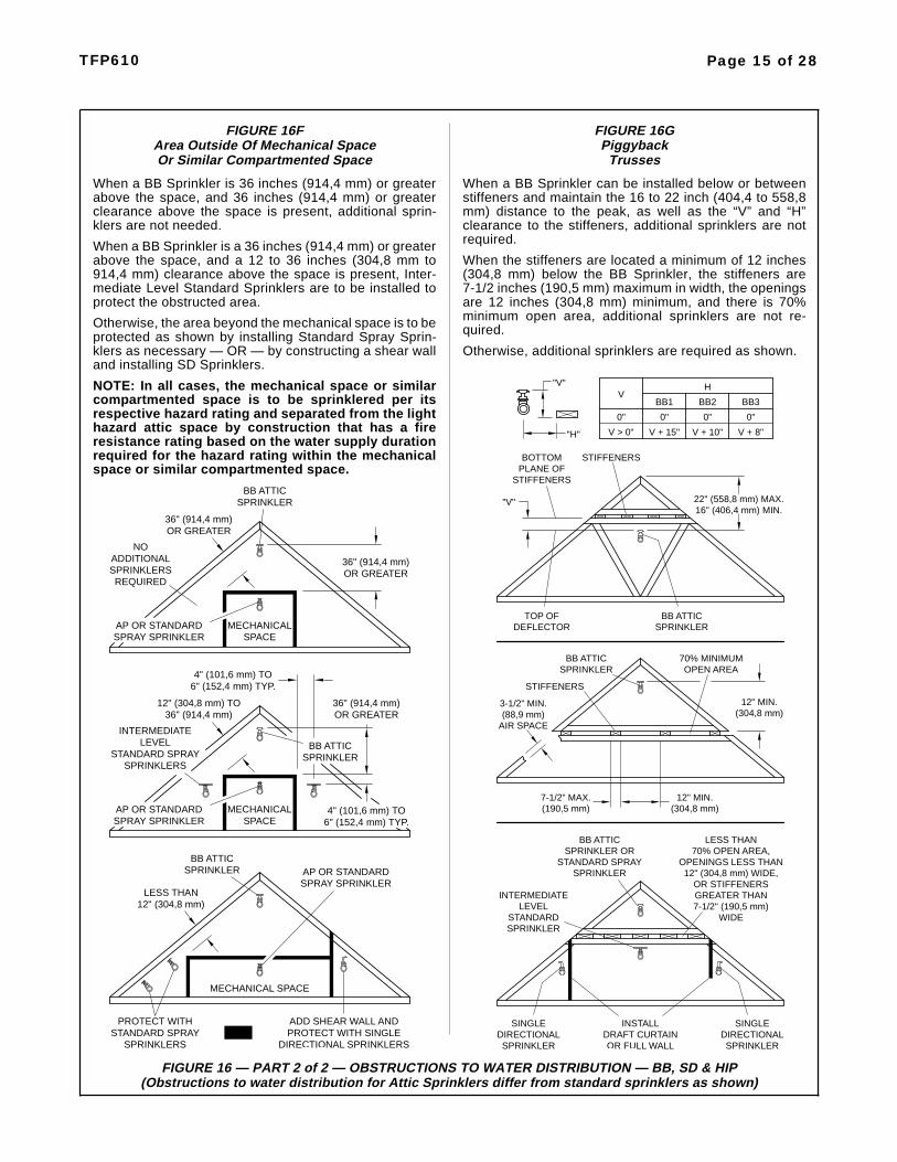
FIGURE 16FArea Outside Of Mechanical SpaceOr Similar Compartmented Space
FIGURE 16GPiggyback
Trusses
When a BB Sprinkler can be installed below or betweenstiffeners and maintain the 16 to 22 inch (404,4 to 558,8mm) distance to the peak, as well as the “V” and “H”clearance to the stiffeners, additional sprinklers are notrequired.
When the stiffeners are located a minimum of 12 inches(304,8 mm) below the BB Sprinkler, the stiffeners are7-1/2 inches (190,5 mm) maximum in width, the openingsare 12 inches (304,8 mm) minimum, and there is 70%minimum open area, additional sprinklers are not re-quired.
Otherwise, additional sprinklers are required as shown.
When a BB Sprinkler is 36 inches (914,4 mm) or greaterabove the space, and 36 inches (914,4 mm) or greaterclearance above the space is present, additional sprin-klers are not needed.
When a BB Sprinkler is a 36 inches (914,4 mm) or greaterabove the space, and a 12 to 36 inches (304,8 mm to914,4 mm) clearance above the space is present, Inter-mediate Level Standard Sprinklers are to be installed toprotect the obstructed area.
Otherwise, the area beyond the mechanical space is to beprotected as shown by installing Standard Spray Sprin-klers as necessary — OR — by constructing a shear walland installing SD Sprinklers.
NOTE: In all cases, the mechanical space or similarcompartmented space is to be sprinklered per itsrespective hazard rating and separated from the lighthazard attic space by construction that has a fireresistance rating based on the water supply durationrequired for the hazard rating within the mechanicalspace or similar compartmented space.
REQUIREDOR GREATER
SPRINKLER
36" (914,4 mm)OR GREATER
4" (101,6 mm) TO6" (152,4 mm) TYP.
ADD SHEAR WALL ANDPROTECT WITH SINGLE
DIRECTIONAL SPRINKLERS
INTERMEDIATE
MECHANICAL
PROTECT WITH
SPRINKLER
-OR-
MECHANICAL SPACE
STANDARD SPRAYSPRINKLERS
12" (304,8 mm)LESS THAN
36" (914,4 mm)12" (304,8 mm) TO
BB ATTIC
4" (101,6 mm) TO6" (152,4 mm) TYP.
STANDARD SPRAYSPRINKLERS
SPACE
LEVEL BB ATTIC
ADDITIONALSPRINKLERS
36" (914,4 mm)OR GREATER
NO
SPRINKLERBB ATTIC
36" (914,4 mm)
AP OR STANDARDSPRAY SPRINKLER
AP OR STANDARDSPRAY SPRINKLER
AP OR STANDARDSPRAY SPRINKLER
MECHANICALSPACE
LEVELSTANDARD
SPRINKLERBB ATTIC
22" (558,8 mm) MAX.16" (406,4 mm) MIN.
BB ATTICSPRINKLER
70% MINIMUMOPEN AREA
(190,5 mm)7-1/2" MAX. 12" MIN.
(304,8 mm)
STANDARD SPRAYSPRINKLER OR
12" (304,8 mm) WIDE,OPENINGS LESS THAN
70% OPEN AREA,
OR STIFFENERS
LESS THAN
GREATER THAN7-1/2" (190,5 mm)
WIDE
SINGLEDIRECTIONALSPRINKLEROR FULL WALL
DRAFT CURTAININSTALL
INTERMEDIATE
SPRINKLER
SINGLEDIRECTIONALSPRINKLER
BB ATTIC
SPRINKLER
STIFFENERS
STIFFENERS
(304,8 mm)12" MIN.
(88,9 mm)3-1/2" MIN.
AIR SPACE
"V"
STIFFENERSPLANE OFBOTTOM
DEFLECTORTOP OF
"V"
"H"
BB1
0"
V + 15"
0"
H
BB2
V + 10"
0"
BB3
V + 8"V > 0"
0"
V

Page 16 of 28 TFP610
FIGURE 18OBSTRUCTIONS TO WATER
DISTRIBUTION FORMODEL AP SPRINKLERS
FIGURE 17AEXPOSED CPVC
WITH AP SPRINKLERSAND
BRANCHLINE OVER JOISTS
FIGURE 17BEXPOSED CPVC WITH AP
SPRINKLERSAND BRANCHLINE WTHIN
JOISTS
APSPRINKLER
C
D
A
OBSTRUCTION
A
APSPRINKLER
APSPRINKLER
A
B
OBSTRUCTION
HorizontalDistance
MinimumVertical DistanceBelow Deflector
(A) (B)6" 3"
( 152,4 mm)>6" to 9"(>152,4 to 228,6 mm)
4"(101,6 mm)
>9" to 12"(>228,6 mm to 304,8 mm)
6"(88,9 mm)
>12" to 15"(>304,8 mm to 381,0 mm)
8"(203,2 mm)
>15" to 18"(>381,0 to 457,2 mm)
9-1/2"(241,3 mm)
>18" to 24"(457,2 mm to 609,6 mm)
12-1/2"(317,5 mm)
>24" to 30"(>609,6 mm to 762,0 mm)
15-1/2"(393,7 mm)
>30"(>762,0 mm)
18"(457,2 mm)
(76,2 mm)
ELEVATION VIEW PLAN VIEW
A 3C or 3DA 24" (609,6 mm)
(Use dimension C or D,
C
D
OBSTRUCTION
whichever is greater)
INSULATION FOR FIREPROTECTION OF CPVC
PIPE, NOT FREEZE
NON-COMBUSTIBLE
PROTECTION
12" MIN.(304,8 mm)
SPRIGAP
SPRINKLERAP
(304,8 mm)12" MIN.
OPTION A
6" MIN.(152,4 mm)
CEILING
JOIST
3'-0" MAX.(0,9 m)
JOIST
NON-COMBUSTIBLE
PIPE, NOT FREEZE
INSULATION FOR FIREPROTECTION OF CPVC
6" MIN.(152,4 mm)
(304,8 mm)12" MIN.
PROTECTION
OPTION B
(304,8 mm)12" MIN.
SPRINKLERAP
APSPRIG
10'-0" MAX.(3,0 m)
CEILING
INSULATION FOR FIREPROTECTION OF CPVC
PIPE, NOT FREEZE
NON-COMBUSTIBLE
PROTECTION
SPRIGAP
SPRINKLERAP
OPTION B
6" MIN.(152,4 mm)
CEILING
INSULATION FOR FIREPROTECTION OF CPVC
NON-COMBUSTIBLE
PROTECTIONPIPE, NOT FREEZE
JOIST
OPTION A
3'-0" MAX.(0,9 m)
CEILING
6" MIN.(152,4 mm)
JOIST
10'-0" MAX.(3,0 m)
SPRINKLER
APSPRIG
AP

TFP610 Page 17 of 28
FIGURE 20 — HYDRAULIC CALCULATIONS
HYDRAULIC CALCULATIONS
Attic sprinklers must be calculated in conformance with these guidelines. In all cases, the design area shall include themost hydraulically demanding sprinklers. More than one set of calculations may be required to prove different situations.
For individual areas requiring more than four AP Sprinklers, the maximum area of attic protected by AP Sprinklers islimited to 3000 ft2 (279 m2) in any single area. Areas must be separated by a minimum of 15 feet (4,6 m) by an areaprotected by BB, SD,or HIP Sprinklers, in order to be considered separate areas.
The hydraulic calculations have been divided into three parts as follows:
• FIGURE 20-A: “Attics Protected Entirely By BB, SD, and HIP Attic Sprinklers”.
20-A-1 (Page 18) BB Sprinklers20-A-2 (Page 18) BB and HIP Sprinklers20-A-3 (Page 19) BB and SD Sprinklers20-A-4 (Page 19) SD Sprinklers20-A-5 (Page 19) SD and HIP Sprinklers20-A-6 (Page 19) HIP Sprinklers
• FIGURE 20-B: “Attics Protected With A Mixture Of BB. SD, and HIP Attic Sprinklers And AP Sprinklers”.
20-B-1 (Page 20) SD Sprinklers & AP Sprinklers At The Ridge20-B-2 (Page 20) BB Sprinklers & AP Sprinklers At The Eaves or Beyond An Obstruction20-B-3 (Page 21) BB Sprinklers & AP Sprinklers At The Hip20-B-4 (Page 21) BB Sprinklers, SD Sprinklers, HIP Sprinklers, & AP Sprinklers At The Hip20-B-5 (Page 22) BB, SD, or HIP Sprinklers & AP Sprinklers in a Dormer, at a Cross, or at an Ell20-B-6 (Page 22) BB,SD, or HIP Sprinklers & AP Sprinklers Separated By Compartmentalization
• FIGURE 20-C: “Attics Protected With A Mixture Of BB. SD, and HIP Attic Sprinklers And Standard SpraySprinklers”.
20-C-1 (Page 23) SD Sprinklers & Standard Spray Sprinklers At The Ridge20-C-2 (Page 23) BB Sprinklers & Standard Spray Sprinklers At The Eaves or Beyond An Obstruction20-C-3 (Page 24) BB Sprinklers & Standard Spray Sprinklers At The Hip20-C-4 (Page 25) BB Sprinklers, SD Sprinklers, HIP Sprinklers, & Standard Spray Sprinklers At The Hip20-C-5 (Page 26) BB, SD, or HIP Sprinklers & Standard Spray Sprinklers in a Dormer, at a Cross, or at an Ell20-C-6 (Page 26) BB, SD, or HIP Sprinklers & Standard Sprinklers Separated By Compartmentalization
BACK TO BACKMODEL BB MODEL SD
SINGLE DIRECTIONALMODEL HIP
MODEL APOR STANDARD
SPRAY
FIGURE 19EXPOSED CPVC WITH BB, SD, AND HIP SPRINKLERS
B
A A
B
A
VERTICAL RISER VERTICAL RISER
BRANCHLINE
VERTICAL SPRIG
ARMOVER SPRIG
ANGLE SPRIG
ARMOVER
DIRECT MOUNT
BRANCHLINE
A = 6" (150 mm) MAX.B = 12" (300 mm) MAX.

Page 18 of 28 TFP610
Figure 20-A-1. BB Sprinklers
• Wet Systems — Calculate themost demanding five sprinklers.
• Dry Systems — Calculate the mostdemanding seven sprinklers (seeadjacent figure).
Figure 20-A-2. BB and HIP Sprin-klers
• Wet Systems — Calculate themost demanding five sprinklers.
• Dry Systems — Calculate themost demanding seven sprin-klers, and then calculate the mostdemanding contiguous nine sprin-klers with a maximum of seven tobe BB Sprinklers (see adjacentfigures). Use the most demandingcalculation.
RIDGE
DRY SYSTEM SHOWN
RIDGE
DRY SYSTEM SHOWN
RIDGE
DRY SYSTEM SHOWN
VALLEY
HIP
HIP

TFP610 Page 19 of 28
Figure 20-A-3. BB and SD Sprin-klers
• Wet Systems — Calculate themost demanding five BB Sprin-klers plus two SD Sprinklers.
• Dry Systems — Calculate themost demanding seven BB Sprin-klers plus up to two SD Sprinklers(see adjacent figure).
Figure 20-A-4. SD Sprinklers
• Wet Systems — Calculate themost demanding five SD Sprin-klers.
• Dry Systems — Calculate themost demanding nine SD Sprin-klers (see adjacent figure).
Figure 20-A-5. SD and HIP Sprin-klers
• Wet Systems — Calculate themost demanding five sprinklers.
• Dry Systems — Calculate the mostdemanding nine sprinklers with amaximum of seven to be SD Sprin-klers (see adjacent figure).
Figure 20-A-6. HIP Sprinklers
• Wet Systems — Calculate themost demanding five sprinklers(see adjacent figure).
• Dry Systems — Calculate themost demanding nine sprinklers.
DRY SYSTEM SHOWN
RIDGE
OBSTRUCTION
DRY SYSTEM SHOWN
RIDGE
WALL ORDRAFT CURTAIN
AT RIDGE
HIP
DRY SYSTEM SHOWN
RIDGE
WALL ORDRAFT CURTAIN
AT RIDGE
WET SYSTEM SHOWN
HIP
HIP
HIP
HIP

Page 20 of 28 TFP610
Figure 20-B-1. SD Sprinklers & APSprinklers At The Ridge
• Wet Systems — Calculate themost demanding five sprinklers ofone type. Use the most demandingcalculation.
• Dry Systems — Calculate the mostdemanding nine SD Sprinklers,and then calculate the most de-manding seven AP Sprinklers. Usethe most demanding calculation(see adjacent figure).
Figure 20-B-2. BB or SD Sprinklers& AP Sprinklers At The Eaves orBeyond An Obstruction
• Wet Systems — Calculate themost demanding five BB or SDSprinklers plus up to two most de-manding AP Sprinklers.
• Dry Systems — Calculate the mostdemanding seven BB or SD Sprin-klers plus up to two most demand-ing AP Sprinklers (see adjacentfigures).
DRY SYSTEM SHOWN
WALLS ORDRAFT
CURTAINS
RIDGE
DRY SYSTEM SHOWN
RIDGE
DRY SYSTEM SHOWN
OBSTRUCTION
RIDGE
DRY SYSTEM SHOWN

TFP610 Page 21 of 28
Figure 20-B-3. BB Sprinklers &AP Sprinklers At The Hip
Where the total number of AP Sprin-klers at the hip is greater than four:
• Wet Systems — Calculate themost demanding five BB Sprin-klers plus the two most demand-ing AP Sprinklers, and then calcu-late the most demanding area upto 1500 ft2 (137 m2) having APSprinklers (e.g., Area 2 in adja-cent upper figure). Use the mostdemanding calculation.
• Dry Systems — Calculate themost demanding seven BB Sprin-klers plus the two most demand-ing AP Sprinklers, and then calcu-late the most demanding area upto 1950 ft2 (181 m2) having APSprinklers(e.g., Area 2 in adjacentupper figure). Use the most de-manding calculation.
Figure 20-B-4. BB Sprinklers, SDSprinklers, HIP Sprinklers, & APSprinklers At The Hip
Where the total number of AP Sprin-klers at the hip is four or less:
• Wet Systems — Calculate themost demanding five BB, SD, orHIP Sprinklers plus up to two mostdemanding AP Sprinklers.
• Dry Systems — Calculate themost demanding nine BB, SD, orHIP Sprinklers plus up to two mostdemanding AP Sprinklers (Of thenine BB, SD, or HIP Sprinklers,calculate up to a maximum ofseven BB Sprinklers, see adjacentupper figure).
Where the total number of AP Sprin-klers at the hip is greater than four:
• Wet Systems — Calculate up tothe most demanding five BB, SD,or HIP Sprinklers plus the twomost demanding AP Sprinklers,and then calculate the most de-manding area up to 1500 ft2 (137m2) having AP Sprinklers(e.g.,Area 2). Use the most demandingcalculation.
• Dry Systems — Calculate up tothe most demanding nine BB, SD,or HIP Sprinklers plus the twomost demanding AP Sprinklers,and then calculate the most de-manding area up to 1950 ft2 (181m2) having AP Sprinklers (e.g.,Area 2). Use the most demandingcalculation.
SEE ALSO FIGURES 21 AND 22
WITH APAREA 2
SPRINKLERS
AREA 1WITH BB
SPRINKLERS
AREA 3WITH AP
SPRINKLERS
15'-0" (4,6 m)
MINIMUMSEPARATION
STAGGEREDSPACING WHEN
MORE THANONE ROW
DRY SYSTEM SHOWN
RIDGE
WALL ORDRAFT
CURTAIN
SEPARATIONMINIMUM
15'-0" (4,6 m)
AREA 1WITH BB & SDSPRINKLERSSPRINKLERS
AREA 2WITH AP
SPRINKLERSWITH APAREA 3

Page 22 of 28 TFP610
Figure 20-B-5. BB, SD, or HIPSprinklers & AP Sprinklers in aDormer, at a Cross, at a Hip, or atan Ell
Where the quantity of AP Sprinklersin each dormer, cross, or ell is fouror less (see adjacent figure) and allof the dormers, crosses and ellsmeet the maximum four AP Sprin-kler criteria, calculate the BB, SD, orHIP Sprinkler demand as describedin Part A-1 thru A-6 or Part B-1 thruB-4, plus up to two of the most de-manding AP Sprinklers in the dor-mer, cross, or ell that is adjacent tothe BB, SD, or HIP Sprinklers thatare being included in the demandcalculation.
Where the quantity of AP Sprinklersin any dormer, cross, or ell isgreater than four, refer to Figure B-3.
Figure 20-B-6. BB,SD, or HIPSprinklers & AP Sprinklers Sepa-rated By Compartmentalization
• Wet Systems— Calculate the BB,SD, or HIP Sprinkler demand asdescribed in Part A-1 thru A-6 orPart B-1 thru B-4, and then calcu-late the most demanding area up to1500 ft2 (137 m2) having AP Sprin-klers. Use the most demanding cal-culation (see adjacent figure).
• Dry Systems— Calculate the BB,SD, or HIP Sprinkler demand asdescribed in Part A-1 thru A-6 orPart B-1 thru B-4, and then calcu-late the most demanding area up to1950 ft2 (181 m2) having AP Sprin-klers. Use the most demanding cal-culation (see adjacent figure).
RIDGE
WALL
RIDGE
DORMERBUILT ON TOPOF ROOF ORSHEATHING
AP
(4 OR LESS)SPRINKLERS
(4 OR LESS)SPRINKLERS
AP
SPRINKLERSAP
(4 OR LESS)
SPRINKLERS(4 OR LESS)
AP

Figure 20-C-1. SD Sprinklers &Standard Spray Sprinklers At TheRidge
• Wet Systems — Calculate the mostdemanding five sprinklers of onetype. Use the most demanding cal-culation.
• Dry Systems — Calculate the mostdemanding nine SD Sprinklers,and then calculate the most de-manding seven Standard SpraySprinklers. Use the most demand-ing calculation (see adjacent fig-
Figure 20-C-2. BB Sprinklers &Standard Spray Sprinklers Be-yond An Obstruction
• Wet Systems — Calculate themost demanding five BB Sprin-klers plus up to two most demand-ing Standard Spray Sprinklers.
• Dry Systems — Calculate the mostdemanding seven BB Sprinklersplus up to two most demandingStandard Spray Sprinklers (seeadjacent figures).
DRY SYSTEM SHOWN
WALLS ORDRAFT
CURTAINS
RIDGE
DRY SYSTEM SHOWN
OBSTRUCTION
RIDGE
TFP610 Page 23 of 28

Figure 20-C-3. BB Sprinklers &Standard Spray Sprinklers At TheHip
Where the total number of standardspray sprinklers at the hip is greaterthan four:
• Wet Systems — Calculate themost demanding five BB Sprin-klers plus up to two most demand-ing Standard Spray Sprinklers,and then calculate the most de-manding remote design area (In-cluding all sprinklers types) perNFPA 13 (i.e., area reduction forquick response & 30% increasefor sloped ceilings). Use the mostdemanding calculation.
• Dry Systems — Calculate themost demanding seven BB Sprin-klers plus up to two most demand-ing Standard Spray Sprinklers,and then calculate the most de-manding design area (including allsprinkler types) per NFPA 13 (i.e.,30% increase for sloped ceilings &30% increase for dry systems). In-clude all sprinklers types withinthis area (see adjacent figure).Use the most demanding calcula-tion.
DRY SYSTEM SHOWN
RIDGE
(235,5 SQ. METERS)2535 SQ. FT.
SECOND CALCULATION
DRY SYSTEM SHOWN
RIDGE
FIRST CALCULATION
Dry Pipe = 1500 SQ. FT. (NFPA Light Hazard) x 1.3 x 1.3 = 2535 SQ. FT.NOTE:
SEE ALSO FIGURES 21 AND 22
Page 24 of 28 TFP610

TFP610 Page 25 of 28
Figure 20-C-4. BB Sprinklers, SDSprinklers, HIP Sprinklers, &Standard Spray Sprinklers At TheHip
Where the total number of StandardSpray Sprinklers at the hip is four orless:
• Wet Systems — Calculate themost demanding five BB, SD, orHIP Sprinklers plus up to two mostdemanding Standard Spray Sprin-klers.
• Dry Systems — Calculate themost demanding nine BB, SD, orHIP Sprinklers plus up to two mostdemanding Standard Spray Sprin-klers (Of the nine BB,SD, or HIPSprinklers, calculate up to a maxi-mum of seven BB Sprinklers, seeadjacent upper figure).
Where the total number of standardspray sprinklers at the hip is greaterthan four:
• Wet Systems — Calculate themost demanding five BB, SD, orHIP Sprinklers plus up to two mostdemanding Standard Spray Sprin-klers, and then calculate the mostdemanding remote design area(Including all sprinklers types) perNFPA 13 (i.e., area reduction forquick response & 30% increasefor sloped ceilings). Use the mostdemanding calculation.
• Dry Systems — Calculate themost demanding nine BB, SD, orHIP Sprinklers plus up to two mostdemanding Standard Spray Sprin-klers (Of the nine BB,SD, or HIPSprinklers, calculate up to a maxi-mum of seven BB Sprinklers, seeadjacent upper figure), and thencalculate the most demanding de-sign area (including all sprinklertypes) per NFPA 13 (i.e., 30% in-crease for sloped ceilings & 30%increase for dry systems). Includeall sprinklers types within this area(see adjacent figure).
DRY SYSTEM SHOWN
DRY SYSTEM SHOWN
RIDGE
WALL ORDRAFT
CURTAIN
RIDGE
(235,5 SQ. METERS)2535 SQ. FT.
DRY SYSTEM SHOWN
RIDGE
FIRST CALCULATION
SECOND CALCULATION
NOTE:Dry Pipe = 1500 SQ. FT. (NFPA Light Hazard) x 1.3 x 1.3 = 2535 SQ. FT.

Page 26 of 28 TFP610
Figure 20-C-5. BB, SD, or HIPSprinklers & Standard SpraySprinklers in a Dormer, at aCross, at a Hip, or at an Ell
Where the quantity of standardspray sprinklers in each dormer,cross, or ell is four or less (see ad-jacent figure) and all of the dormers,crosses and ells meet the maximumfour standard sprinkler criteria, cal-culate the Attic Sprinkler demand asdescribed in Part A-1 thru A-6 orPart B-1 thru B-4, plus up to two ofthe most demanding standard spraysprinklers in the dormer, cross, orell that is adjacent to the Attic Sprin-klers that are being included in thedemand calculation.
Where the quantity of standardspray sprinklers in any dormer,cross, or ell is greater than four,refer to Figure C-3.
Figure 20-C-6. BB, SD, or HIPSprinklers & Standard SprinklersSeparated By Compartmentaliza-tion
Calculate the Attic Sprinkler demandas described in Part A-1 thru A-6 orPart C-1 thru C-4, and then calculatethe Standard Spray Sprinklers perNFPA 13. Use the most demandingcalculation (see adjacent figure).
RIDGE
WALL
RIDGE
DORMERBUILT ON TOPOF ROOF ORSHEATHING
STANDARD SPRAY
(4 OR LESS)SPRINKLERS
(4 OR LESS)SPRINKLERS
STANDARD SPRAY
SPRINKLERSSTANDARD SPRAY
(4 OR LESS)
SPRINKLERS(4 OR LESS)
STANDARD SPRAY

TFP610 Page 27 of 28
FIGURE 21EXAMPLE FOR A WET PIPE SYSTEM HYDRAULIC DESIGN AREA COMPARISON
OF MODEL AP SPRINKLERS VERSES STANDARD SPRAY SPRINKLERSWHERE MODEL AP OR STANDARD SPRAY SPRINKLERS ARE USED IN HIP AREAS
OUTSIDE THE SCOPE OF APPLICATION FOR MODEL BB BACK-TO-BACK SPRINKLERS
MODEL AP SPRINKLERS
WET PIPE SYSTEM
(Ref. Figure 20-B-3)
Calculation 1:Calculate the most demanding five BBSprinklers plus the two most demand-ing AP Sprinklers.
Calculation 2:Calculate the most demanding area upto 1500 ft2 having AP Sprinklers. In thiscase the design area will be 800 ft2 (40ft. x 20 ft.)
Use the most demanding calculation(i.e., for proving the adequacy of thewater supply).
Where AP Sprinklers are utilized,CPVC pipe may be used to supply theAP Sprinklers, as well as the ceilingsprinklers below the AP Sprinklers(See Page 6).
STANDARD SPRAY SPRINKLERS
WET PIPE SYSTEM
(Ref. Figure 20-C-3)
Calculation 1:Calculate the most demanding five BBSprinklers plus the two most demand-ing Standard Spray Sprinklers.
Calculation 2:Calculate the most demanding remotedesign area (Including all sprinklerstypes) per NFPA 13 (i.e., area reduc-tion for quick response & 30% increasefor sloped ceilings). In this case thetheoretical design area is 1463 ft2(1500 ft2 x 0.75* x 1.3). The actualdesign area, however, will need to be1520 ft2 to pick up the entire coveragearea of the last BB Sprinkler.
Use the most demanding calculation(i.e., for proving the adequacy of thewater supply).
Where Standard Sprinklers are util-ized, CPVC pipe CANNOT be used tosupply the Standard Spray Sprinklersor the ceiling sprinklers below theStandard Spray Sprinklers.
* A 25% reduction for 20 ft. ceiling.
100' (25,4 m)
60' (15,2 m)20'
(5,1 m)(5,1 m)20'
(10,2 m)40'
(5,1 m)20'
60' (15,2 m)
100' (25,4 m)
(5,1 m)20'
12
12
Calculation 1
Calculation 240'
(10,2 m)
(5,1 m)
(10,2 m)
(5,1 m)
40'
20'100' (25,4 m)
60' (15,2 m)
Calculation 2
20'
(5,1 m)
(10,2 m)40'
20'(5,1 m)
100' (25,4 m)
60' (15,2 m)
12
12
Calculation 1
20'

Page 28 of 28 TFP610
© 2007-2008 TYCO FIRE & BUILDING PRODUCTS, 451 North Cannon Avenue, Lansdale, Pennsylvania 19446
FIGURE 22EXAMPLE FOR A DRY PIPE SYSTEM HYDRAULIC DESIGN AREA COMPARISON
OF MODEL AP SPRINKLERS VERSES STANDARD SPRAY SPRINKLERSWHERE MODEL AP OR STANDARD SPRAY SPRINKLERS ARE USED IN HIP AREAS
OUTSIDE THE SCOPE OF APPLICATION FOR MODEL BB BACK-TO-BACK SPRINKLERS
MODEL AP SPRINKLERS
DRY PIPE SYSTEM
(Ref. Figure 20-B-3)
Calculation 1:Calculate the most demanding sevenBB Sprinklers plus the two most de-manding AP Sprinklers.
Calculation 2:Calculate the most demanding area upto 1950 ft2 having AP Sprinklers. In thiscase the design area will be 800 ft2 (40ft. x 20 ft.)
Use the most demanding calculation(i.e., for proving the adequacy of thewater supply).
STANDARD SPRAY SPRINKLERS
DRY PIPE SYSTEM
(Ref. Figure 20-C-3)
Calculation 1:Calculate the most demanding sevenBB Sprinklers plus the two most de-manding Standard Spray Sprinklers.
Calculation 2:Calculate the most demanding remotedesign area (Including all sprinklerstypes) per NFPA 13 (i.e., 30% increasefor sloped ceilings & 30% increase fordry systems). In this case the theoreti-cal design area will be 2535 ft2 (1500ft2 x 1.3 x 1.3). The actual design area,however, will need to be 2720 ft2 to pickup the entire coverage area of the lastBB Sprinkler.
Use the most demanding calculation(i.e., for proving the adequacy of thewater supply).
100' (25,4 m)
60' (15,2 m)(5,1 m)
(10,2 m)40'
20'(5,1 m)
Calculation 2
20'
60' (15,2 m)
100' (25,4 m)
40'(10,2 m)
(5,1 m)20'
Calculation 1
20'(5,1 m)
12
12
(5,1 m)
(5,1 m)
(10,2 m)40'
20'
40'(10,2 m)
20'
12
12
Calculation 2
(5,1 m)
100' (25,4 m)
60' (15,2 m)20'
Calculation 1
100' (25,4 m)
60' (15,2 m)20'
(5,1 m)