models 250, 400 and 600 - apc.com · ne pas installer la source d’alimentation permanente (ups)...
TRANSCRIPT

Back-UPS®
Models 250,400 and 600
User'sUser'sUser'sUser'sUser'sManualManualManualManualManual

Important safety instructions!Please read this manual!Veuillez lire ce manuel!Bitte lesen Sie dieses Anleitungshandbuch!¡Se ruega leer este manual de instrucciones!
Thank you for selecting this American Power Conversion Uninterruptible PowerSource (UPS). It has been designed for many years of reliable, maintenance freeservice. American Power Conversion is dedicated to the development of highperformance electrical conversion and control products and we hope that youwill find this UPS a valuable, convenient addition to your computing system.
This manual provides safety, installation and operating instructions that will helpyou derive the fullest performance and service life that the UPS has to offer. Inaddition, the manual describes the inner workings of the UPS and how they relateto providing superior protection from utility power problems such as blackouts,brownouts, sags, swells, EMI/RFI noise and surges.
Please save this manual!It includes important instructions for the safe use of this UPS and for obtainingfactory service should the proper operation of the UPS come into question. Downthe road, service or storage issues may arise and require reference to this manual.
Please save or recycle the packaging materials!The UPS's shipping materials were designed with great care to provide protectionfrom transportation related damage. The shipping materials will become invalu-able to you in case the UPS must be returned to the factory for service (damagessustained in transit when shipped from the user are not covered under warranty).
Entire contents copyright © 1993 American Power Conversion. All rights reserved; reproduction in whole or in part withoutpermission is prohibited. Back-UPS and PowerChute are registered trademarks of APC. All other trademarks are the property
of their respective owners.

Page 1
Table of contents1.0 Introduction................................................................ 2
2.0 Safety! ........................................................................ 3Sécurité! (Françias)....................................................................................... 4Sicherheit! (Deutsch) ................................................................................... 5Seguridad! (Español) ................................................................................... 6
3.0 Installation ................................................................. 7
4.0 Principles of operation .............................................. 13
5.0 Controls and indicators ............................................. 18
6.0 UPS monitoring......................................................... 19
7.0 Difficulty ................................................................... 21Difficulté (Françias) ................................................................................... 22Schwierigkeit (Deutsch) ............................................................................ 23Dificultad (Español) .................................................................................. 24
8.0 Storing the UPS......................................................... 29
9.0 Run time versus load................................................. 30
10.0 Specifications ............................................................ 31
Warranty, Life support policy ................................ cover

Page 2
1.0 Introduction1.1 Overview
The UPS is a high performance standby uninterruptible power source designedto protect computers and peripheral devices such as monitors, modems, tapedrives, etc. from utility line failures which could result in the loss or corruptionof valuable data. In the event of a utility failure such as a blackout, brownout,swell or sag, the UPS rapidly transfers loads (computer equipment) to analternative power source. This alternative power is derived from a battery withinthe UPS and provides the user with ample time to save files and properly closeoperations. A chart in section 9.0 shows how much time your equipment canremain operating during a utility failure before the UPS’s batteries are drained.Under normal conditions when the utility voltage is within proper limits, theUPS maintains the battery in a charged condition and serves to isolate yourequipment from surges and high frequency electrical noise.
After following the installation procedures and reading all the safety instruc-tions, you’re ready to enjoy computing free from the worry of power problemsand the time consuming process of constantly saving your files!
1.2 Surge suppression and EMI/RFI filtering
The UPS provides high performance surge suppression and EMI/RFI (electro-magnetic and radio frequency interference) filtering. The UPS suppresses surgesdefined by the ANSI C62.41 (formerly IEEE 587) Category A and B standard tolevels well below that which is compatible with your computer.
1.3 Remote interface
A remote computer interface port (400VA and 600VA models) capable of signal-ling utility failure and low battery conditions is provided for unattended shut-down of computer operations. When teamed with PowerChute UPS monitoringsoftware, you may select operation of power event logging, power event notifi-cation, automatic restart upon power restoration, and battery conservationfeatures.

Page 3
2.0 Safety !■ To reduce the risk of electric shock, disconnect the Uninterruptible Power Sourcefrom the mains before installing a computer interface signal cable (when used).Reconnect the power cord only after all signalling interconnections have been made.
■ Connect the Uninterruptible Power Source to a two-pole, three-wire groundingmains receptacle. The receptacle must be connected to appropriate branch protection(fuse or circuit breaker). Connection to any other type of receptacle may result in ashock hazard and may violate local electrical codes.
■ This Uninterruptible Power Source has an internal energy source (the battery) thatcannot be de-energized by the user. The output may be energized when the unit isnot connected to a mains supply.
■ To properly de-energize the Uninterruptible Power Source in an emergency, movethe I/O switch to the O (off) position and disconnect the power cord from the mains.
■ Avoid installing the Uninterruptible Power Source in locations where there is wateror excessive humidity.
■ Do not allow water or any foreign object to get inside the Uninterruptible PowerSource. Do not put objects containing liquid on or near the unit.
■ To reduce the risk of overheating the Uninterruptible Power Source, avoid exposingthe unit to the direct rays of the sun. Avoid installing the unit near heat emittingappliances such as a room heater or stove.
■ The Protective Earth conductor of this UPS carries the Leakage Current from theload devices (computer equipment). This UPS generates approximately 0.75 mA ofleakage current. To ensure a safe limit of 3.5 mA, the total leakage current of the loaddevices should be limited to 2.75 mA. If you are unsure of the leakage current fromthe load devices, ensure that this product is plugged into a 3-wire receptacle that hasa reliable (low impedance) Protective Earth connection to provide a safe path for theleakage current, and replace the powercord to the UPS with one that has a locking typeplug (IEC 309) rated a minimum of 10 A. This powercord may require the services ofa professional electrician for the installation of the matching wall receptacle.
ENGLISH
Page 4
2.0 Sécurité !■ Pour réduire le risque d’électrocution, débranchez la prise principale de la sourced’alimentation permanente (Uninterruptible Power Source), avant d’installer le câbled’interface allant à l’ordinateur (si utilisé). Ne rebranchez le bloc d’alimentationqu’après avoir effectué toutes les connections.
■ Branchez la source d’alimentation permanente (UPS) dans une prise de courant à3 dérivations (deux pôles et la terre). Cette prise doit être munie d’une protectionadéquate (fusible ou coupe-circuit). Le branchement dans tout autre genre de prisepourrait entraîner un risque d’électrocution et peut constituer une infraction à laréglementation locale concernant les installations électriques.
■ Cette source d’alimentation permanente (UPS) est munie d’une source d’énergieinterne (accumulateur) qui ne peut pas être désactivée par l’utilisateur. La prise desortie peut donc être sous tension même lorsque l’appareil n’est pas branché.
■ En cas d’urgence, pour désactiver correctement la source d’alimentation permanente(UPS), poussez l’interrupteur sur la position O (Off) et débranchez le cordond’alimentation principal.
■ Ne pas installer la source d’alimentation permanente (UPS) dans un endroit où ily a de l’eau ou une humidité excessive.
■ Ne pas laisser de l’eau ou tout objet pénétrer dans la source d’alimentationpermanente (UPS). Ne pas placer de récipients contenant un liquide sur cet appareil,ni à proximité de celui-ci.
■ Pour éviter une surchauffe de la source d’alimentation permanente (UPS),conservez-la à l’abri du soleil. Ne pas installer à proximité d’appareils dégageant dela chaleur tels que radiateurs ou appareils de chauffage.
■ Le conducteur de terre de protection de cette UPS (Alimentation ininterrompue encourant) achemine le courant de fuite provenant des dispositifs de charge (équipementd’ordinateur). Cette UPS crée environ 0,75 mA de courant de fuite. Pour garantir unelimite de sécurité de 3,5 mA, le courant total de fuite des dispositifs de charge doit êtrelimité à 2,75 mA. Si vous n’êtes pas sûr du courant de fuite provenant des dispositifsde charge, assurez que ce produit soit enfiché dans une prise à 3 fils ayant uneconnexion de terre de protection fiable (à basse impédance) procurant un chemin sûrau courant de fuite, et remplacez le cordon secteur allant à l’UPS par un qui ait unefiche du type à verrouillage (IEC 309) et à valeur nominale de 10 A. Ce cordon secteurpeut exiger les services d’un électricien professionnel pour l’installation de la prisemurale correspondante.
FRANÇAIS

Page 5
2.0 Sicherheit !■ Um die Gefahr eines elektrischen Schlages auf ein Minimum zu reduzieren, dieunterbrechungsfreie Stromversorgung vom Stromnetz trennen, bevor ggf. ein Com-puter-Schnittstellensignalkabel angeschlossen wird. Das Netzkabel erst nachHerstellung aller Signalverbindungen wieder einstecken.
■ Die unterbrechungsfreie Stromversorgung an eine geerdete zweipolige Dreiphasen-Netzsteckdose anschließen. Die Steckdose muß mit einem geeigneten Abzweigschutz(Sicherung oder Leistungsschalter) verbunden sein. Der Anschluß derunterbrechungsfreien Stromversorgung an einen anderen Steckdosentyp kann zuStromschlägen führen und gegen die örtlichen Vorschriften verstoßen.
■ Diese unterbrechungsfreie Stromversorgung besitzt eine interne Energiequelle(Batterie), die vom Benutzer nicht abgeschaltet werden kann. Der Ausgang kanneingeschaltet werden, wenn das Gerät nicht an das Stromnetz angeschlossen ist.
■ Um die unterbrechungsfreie Stromversorgung im Notfall ordnungsgemäßabzuschalten, den I/O-Schalter an der Rückseite auf O (Aus) stellen und das Netzkabelaus der Steckdose ziehen.
■ Die unterbrechungsfreie Stromversorgung nicht an einem Ort aufstellen, an dem sie mitWasser oder übermäßig hoher Luftfeuchtigkeit in Berührung kommen könnte.
■ Darauf achten, daß weder Wasser noch Fremdkörper in das Innere derunterbrechungsfreien Stromversorgung eindringen. Keine Objekte, die Flüssigkeitenthalten, auf oder neben die unterbrechungsfreie Stromversorgung stellen.
■ Um ein Überhitzen der unterbrechungsfreien Stromversorgung zu verhindern,das Gerät vor direkter Sonneneinstrahlung fernhalten und nicht in der Nähe vonwärmeabstrahlenden Haushaltsgeräten (z.B. Heizgerät oder Herd) aufstellen.
■ Der Erdableitstrom des Verbrauchers (Computer) fließt über den Schutzleiter desUPS-Netzgerätes ab Das UPS-Netzgerät selbst erzeugt einen Erdableitstrom von ca0,75 mA. Um den Sicherheitsgrenzwert von 3,5 mA nicht zu überschreiten, sollte derErdableitstrom sämtlicher Verbraucher auf 2,75 mA begrenzt sein. Wenn Ihnen dieHöhe des Ableitstromes von den Verbrauchern nicht bekannt ist, dann sorgen Siedafür, daß dieses Gerät an eine Steckdose mit Schutzkontakt angesschlossen wird,der eine zuverlässge (geringe Impedanz) Schutzleiterverbindung hat, um einensicheren Strompfad für den Erdableitstrom zu gewährleisten. Ersetzen Sie zudem dieNetzanschlußleitung des UPS-Netzgerätes durch eine Netzanschlußleitung miteiner verriegelbaren, industriellen Steckvorrichtung (nach IEC 309), die für mindestens10 Ampere ausgelegt ist. Eine derartige Netzanschlußleitung erfordert eventuell dieInstallation einer entsprechenden Netzsteckdose in der Wand durch einen Elektriker.
DEUTSCH

Page 6
2.0 ¡ Seguridad !■ Para reducir el riesgo de descarga eléctrica, desconecte de la red la Fuente de energíaininterrumpible antes de instalar el cable de señalización de interfaz de la computadora(si se usa). Vuelva a conectar el conductor flexible de alimentación solamente una vezefectuadas todas las interconexiones de señalización.
■ Conecte la Fuente de energía ininterrumpible a un tomacorriente bipolar y trifilarcon neutro de puesta a tierra. El tomacorriente debe estar conectado a la protecciónde derivación apropiada (ya sea un fusible o un disyuntor). La conexión a cualquierotro tipo de tomacorriente puede constituir peligro de descarga eléctrica y violar loscódigos eléctricos locales.
■ Esta Fuente de energía ininterrumpible tiene una fuente de energía interna (labatería) que no puede ser desactivada por el usuario. La salida puede tener corrienteaun cuando la unidad no se encuentre conectada al suministro de red.
■ Para desactivar correctamente la Fuente de energía ininterrumpible en unasituación de emergencia, coloque el interruptor I/O en la posición O (Off -desconectado)y desconecte de la red el conductor flexible de alimentación.
■ No instale la Fuente de energía ininterrumpible en lugares donde haya agua ohumedad excesiva.
■ No deje que en la Fuente de energía ininterrumpible entre agua ni ningún objetoextraño. No ponga objetos con líquidos encima de la unidad ni cerca de ella.
■ Para reducir el riesgo de sobrecalentamiento, no exponga la unidad a los rayosdirectos del sol ni la instale cerca de artefactos que emiten calor, como estufas ococinas.
■ El conductor de protección a tierra conduce las corrientes de fuga de esta fuenteininterrumpible de potencia (UPS) generadas en los componentes de carga (equiposde computadora). La fuente ininterrumpible de potencia genera aproximadamente0,75 mA de corriente de fuga. Para garantizar un límite de seguridad de 3,5 mA, eltotal de la corriente de fuga de los componentes de carga deberá limitarse a 2,75 mA.Si usted no está seguro del total de las corrientes de fuga de los componentes,asegúrese de que este producto esté conectado a un receptáculo de tres conductoresque tenga una conexión de protección a tierra que sea confiable (impedancia baja)para proveer un camino seguro para la corriente de fuga. También asegúrese dereemplazar el cable que va a la fuente ininterrumpible de potencia con uno que tengaun enchufe con dispositivo de cierre (IEC 309) con capacidad para un mínimo de 10A.Este cable pudiera requerir los servicios de un eletricista profesional para la instalacióndel receptáculo en la pared.
ESPAÑOL

Page 7
3.0 Installation3.1 Receiving inspection
Once the UPS has been removed from its shipping container, it should beinspected for damage that may have occurred while in transit. Immediatelynotify the carrier and place of purchase if any damage is found. Two outputjumper cords are provided with the UPS. The packing materials are made fromrecyclable materials and should be saved for reuse or disposed of properly.
3.2 Placement
The UPS may be installed in any protected environment. The location shouldprovide adequate air flow around the unit, in an atmosphere free from excessivedust, corrosive fumes or conductive contaminants. Do not operate the UPS in anenvironment where the ambient temperature or humidity is outside the limitsgiven in the Specifications section of this manual.
3.3 Load types
The UPS is designed to power all modern computer loads and associatedperipheral devices such as monitors, modems, cartridge tape drives, externalfloppy drives, etc. The UPS is not rated to power life support equipment (asdescribed on the rear cover of this manual).
Caution: The output waveform of this UPS is a sine wave approximation suitable foruse with modern computer power supplies. Other load types may malfunction. Inparticular, ferroresonant type regulating transformers are not recommended. Use of asurge suppressor connected to the output of this UPS may unnecessarily load the UPSwhen on-battery. This UPS contains high performance surge suppression - additionalsuppression components are not required and are not recommended. If in doubt, pleaseconsult the equipment manufacturer or the factory.
Page 8
3.0 Installation3.4 Connecting to the utility
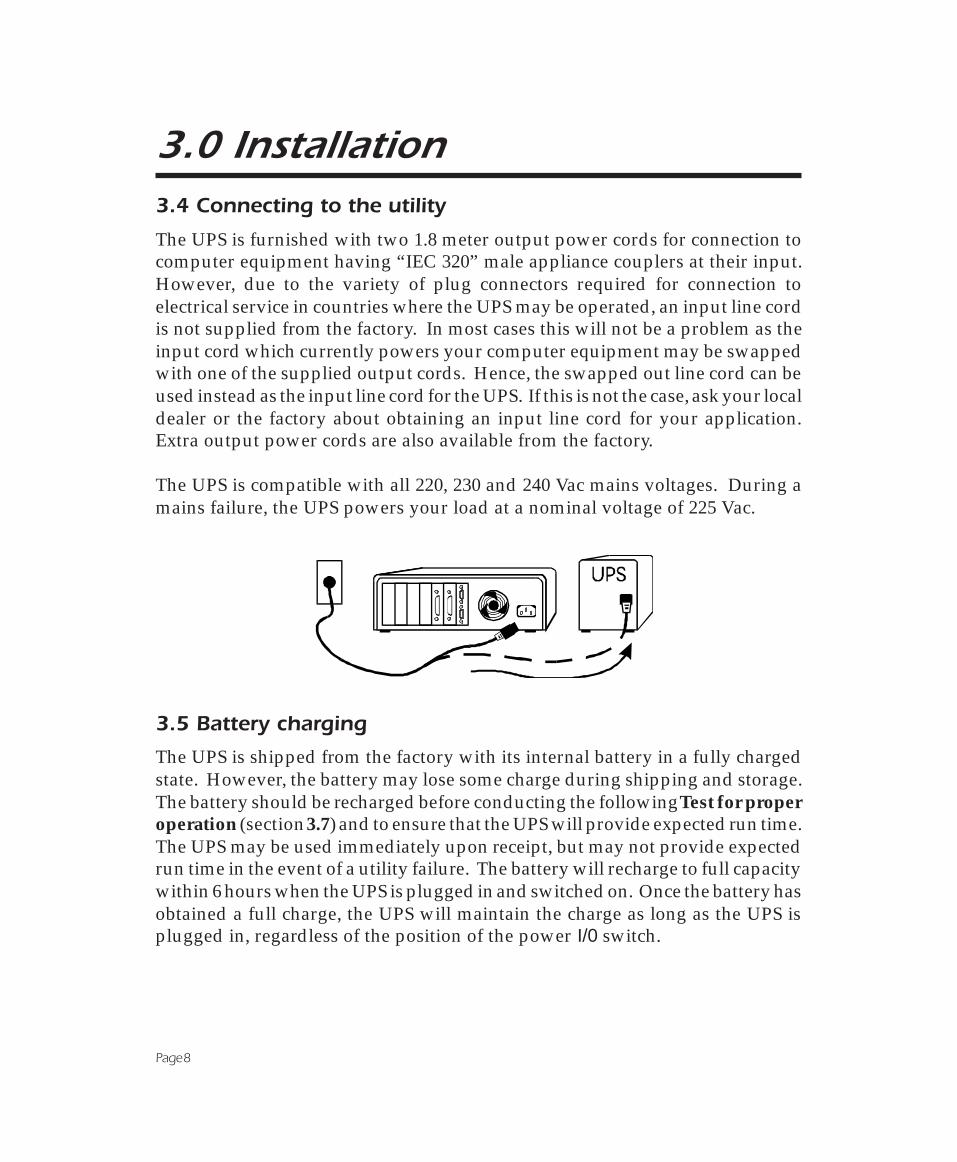
The UPS is furnished with two 1.8 meter output power cords for connection tocomputer equipment having “IEC 320” male appliance couplers at their input.However, due to the variety of plug connectors required for connection toelectrical service in countries where the UPS may be operated, an input line cordis not supplied from the factory. In most cases this will not be a problem as theinput cord which currently powers your computer equipment may be swappedwith one of the supplied output cords. Hence, the swapped out line cord can beused instead as the input line cord for the UPS. If this is not the case, ask your localdealer or the factory about obtaining an input line cord for your application.Extra output power cords are also available from the factory.
The UPS is compatible with all 220, 230 and 240 Vac mains voltages. During amains failure, the UPS powers your load at a nominal voltage of 225 Vac.
3.5 Battery charging
The UPS is shipped from the factory with its internal battery in a fully chargedstate. However, the battery may lose some charge during shipping and storage.The battery should be recharged before conducting the following Test for properoperation (section 3.7) and to ensure that the UPS will provide expected run time.The UPS may be used immediately upon receipt, but may not provide expectedrun time in the event of a utility failure. The battery will recharge to full capacitywithin 6 hours when the UPS is plugged in and switched on. Once the battery hasobtained a full charge, the UPS will maintain the charge as long as the UPS isplugged in, regardless of the position of the power I/0 switch.

Page 9
3.0 Installation3.6 Connecting your equipment to the UPS
To ensure that your computer equipment will be protected during a utility failureand that you receive expected run time, it is important that you determine thetotal power needs of the equipment you wish to protect with the UPS. The powerrequirements of your equipment should be less than or equal to the capacity ofthe UPS. The capacity rating of the UPS, in both Volt-Amperes (VA) and Watts(W), is given in the Specifications section of this manual.
The power demands of your equipment can be read from the Run Time VersesLoad (section 9.0) chart or may be deduced from the equipment name plates. TheRun Time Versus Load chart gives equipment power requirements (load) in VAfor computer systems common in the office environment today. If your equip-ment is not listed in the chart, the following instructions will help you todetermine their power needs.
3.6.1 Computer equipment manufacturers must provide a load rating for theirproducts. Usually, the rating is written on a name plate or label near the line cord.The rating may be given in units of Amps (A or Amax), Volt-Amperes (VA) orWatts (W). Jot down the load rating of all the equipment you wish to protect.
3.6.2 All noted load ratings should be converted to Volt-Amperes (VA) so that allequipment power requirements can be added using the same units of measure.
3.6.3 If load ratings are given in Watts (W), convert to an estimate of powerrequirements in VA by multiplying the value in Watts by 1.4.
3.6.4 If load ratings are given in Amps (A or Amax), convert to an estimate ofpower requirements in VA by multiplying the value in Amps by 230. Unfortu-nately, many computer manufacturers overrate the power requirements of theirequipment in order to be conservative and to cover the extra power demand ofuser added expansion boards. If the VA requirement that you have computedseems high or is already greater than the capacity of the UPS, don’t worry. Thenext section describes a test that you can perform to determine whether or notyour equipment and the UPS are compatible, even if the computed powerrequirement of your equipment is 50% greater than the capacity of the UPS!

Page 10
3.0 Installation3.6.5 Once all power requirement figures have been converted to VA units andadded together, simply determine whether the power requirements of yourequipment is less than or equal to the capacity of the UPS. If this is not the case,then it must be decided which equipment should be left unprotected by the UPS.See section 3.8 covering overloads.
3.6.6 An example of how to determine the power requirements of a computersystem is given below.
Example - labels found at system equipment rear panels
The power requirements of the example computer, monitor and external tapedrive may be calculated as follows:
Computer VA = 230 x 2 A = 240 VAMonitor VA = 100 x 1.4 = 140 VA
Tape Drive VA = 230 x 1 A = 120 VA_______________
Total = 500 VA
In this example, a UPS with at least 500 VA capacity can be employed to protectthe computer, monitor and external tape drive. However, a UPS with somewhatlower capacity may still be used if the following test for proper operation issuccessful.

Page 11
3.0 Installation3.6 Connecting your equipment to the UPS - continued
3.6.7 Once you have determined that your equipment and the UPS are compat-ible, plug your equipment into the UPS’s rear panel output receptacles.
Note: Do not plug laser printers into this UPS! The power requirements of a typical laserprinter are much larger than the requirements of other computer peripherals and may tripthe UPS’s rear panel circuit breaker. Plug laser printers into a quality surge suppressor.Remember that print jobs can be re-queued when the power is restored!
3.7 Test for proper operation
After the UPS has had a chance to recharge its battery, turn on the UPS’s powerI/0 control and switch on your computer equipment. The indicator within theswitch should be illuminated and your equipment should operate normally.
To test the operation of the UPS, simply unplug its input cord or press and holdthe Test switch (on units so equipped) to simulate a utility blackout. The lampwithin the power I/0 switch will flash and UPS will immediately transfer yourequipment to power derived from the UPS’s internal battery. During this time,the UPS will emit a series of four beeps once every 30 seconds to remind you thatyour equipment is operating from a source of power that is limited in duration.Restore normal operation by releasing the Test control or by plugging in the line

Page 12
cord. Observe that your equipment operates normally during both transfer fromutility power to UPS power and back again. Repeat this test four or five times toensure proper operation. See the following section covering Overloads ifabnormal operation is encountered.
The power I/0 control switches power to your equipment. If you leave yourequipment power switches on, the I/0 power control can be used as a master on/off switch!
3.8 Overloads
If the total power requirement of your equipment is much greater than thecapacity of the UPS, the UPS’s rear panel circuit breaker may trip. This is calledan overload situation. Once the circuit breaker trips, the UPS will attempt tooperate the load using its internal power source. This may result in an unexpect-edly short run time or, if the overload is severe, the UPS will immediately shutdown and cease to power the load. In this case, the UPS will emit a loud tone toalert you of the overload. If this occurs during your test, turn off the UPS anddecide which equipment will be left unprotected by the UPS. The circuit breakermay be reset (press button) when the overload is removed.
3.0 Installation3.7 Test for proper operation - continued

Page 13
4.0 Principles of operation
Below is a block diagram showing the major components of your UPS. Theseblocks are described on the following pages.
Block diagram showing all major components of your UPS.

Page 14
4.0 Principles of operation4.1 Noise and surge suppression
The UPS contains high performance EMI/RFI (Electro-Magnetic and RadioFrequency Interference) noise and surge suppression circuitry to protect yourcomputer equipment. The UPS provides this suppression continuously, whetheror not it is turned on. Normally, the UPS suppresses noise and surges withoutyour notice; that is, the UPS doesn’t transfer your load to its internal powersource. Instead, the suppression circuitry reduces the amplitude of noise andsurges to a level well below that which can be tolerated by your relatively delicatecomputing equipment.
The illustration above shows what a typical “medium” amplitude surge or spikelooks like when present on the utility voltage. Surges up to 15 times larger thanthis are easily suppressed by the UPS. Surges are commonly caused by nearbylightning activity and motor load switching created in air conditioners, elevatorsand heat pumps.
The illustration above shows what EMI/RFI noise looks like when present on theutility voltage. The UPS “filters” out this noise with components whose electricalresistance is very high at radio frequencies. EMI/RFI noise is commonly createdby the same activity which produces surges but can also be caused by nearbyradio transmitters and blinking neon bulbs and signs.
Page 15
4.0 Principles of operation4.2 Load transfer switch
The load transfer switch is actually an electro-dynamic relay which serves torapidly transfer your computer equipment (load) from the utility to the UPS’salternate power source in the event of a utility failure. When the utility is restoredto within safe limits, the switch acts to re-transfer the load to the utility. Exceptfor the user control switches, the transfer switch is the only moving part in theUPS. The time required for the relay to transfer your load to either power sourceis much, much faster than that which is required by any modern computer orcomputer peripheral device.
4.3 Battery charger
The UPS’s battery charger converts the alternating current (AC) supplied by theutility to a direct current (DC) which is compatible with the battery. The chargermaintains the battery at a constant voltage to ensure that the battery will have thecapacity to support your load as often as possible. This charging method, knownas “float” charging, provides maximum battery service life and minimal internalheating. The battery is charged at an accelerated rate as required whenever theUPS is plugged in and switched on. When switched off, the battery is "tricklecharged" in order to maintain full capacity.
4.4 Battery
The UPS’s battery is an energy source much like the battery in an automobile.Also, like most automobile batteries, the UPS’s battery is a modern maintenancefree lead-acid type; it is sealed and leakproof. The battery has a typical servicelife of 3 to 6 years. The service life is extended when the UPS is kept in a coolenvironment, below 30°C or 86°F.
4.5 Inverter
The UPS must convert the battery’s energy into a form that your computerequipment can rely upon during a utility failure. This is the job of the UPS’sinverter. The UPS converts the battery’s DC to AC using solid state devices(transistors), controlled using a technique known technically as “pulse widthmodulation”. This technique is highly efficient which means that little batterypower is wasted in the conversion process. Hence, your equipment can run forlong periods from the UPS before the battery’s capacity is spent.

Page 16
4.6 Transformer
The UPS’s transformer is an electrical component which “steps up” the outputvoltage of the inverter to the normal utility line voltage. In addition, it serves toisolate the UPS from equipment failures.
4.7 Monitoring and control electronics
This block is the “brain” of the UPS. The monitoring and control circuitry detectsutility failures such as blackouts, sags and brownouts; synchronizes the inverter’soutput frequency and phase to that of the utility; detects low battery voltageconditions; directs the load transfer switch; and governs all user controls,indicators and computer interface functions.
4.8 Operation during a utility failure
In anticipation of a utility failure such as a blackout, swell, sag or brownout, theUPS continuously monitors the utility voltage and readies the inverter for“synchronous” transfer. This means the inverter’s phase and frequency isadjusted to match the phase and frequency of the utility. If the utility voltage fallsoutside acceptable limits, the UPS rapidly transfers your equipment to powerderived from the UPS’s battery via the inverter and transformer described earlier.This transfer typically takes place within 3 milliseconds. Once operating in thismode, the UPS will emit a series of four beeps once every 30 seconds to remindyou that the continuation of power is limited in duration. If the utility power isnot restored to normal, the UPS will eventually sound continuous beeps to alertyou that less than two minutes remain before the UPS shuts down and ceases topower your equipment. This is called a low battery condition which means thatthe UPS’s usable battery capacity is nearly spent. The UPS will automaticallyshut down if the UPS is not turned off during the low battery alarm.
If the UPS detects the return of normal utility voltages at any time duringoperation using its alternate power source, the inverter voltage will be smoothlyre-synchronized to match the phase and frequency of the utility. Once synchro-nized, the load transfer switch will re-transfer your equipment to power suppliedby the utility. After an extended utility outage, the battery charger resupplies thebattery with energy at a pace which is consistent with maximizing the service life
4.0 Principles of operation
Page 17
4.0 Principles of operation4.8 Operation during a utility failure (continued)
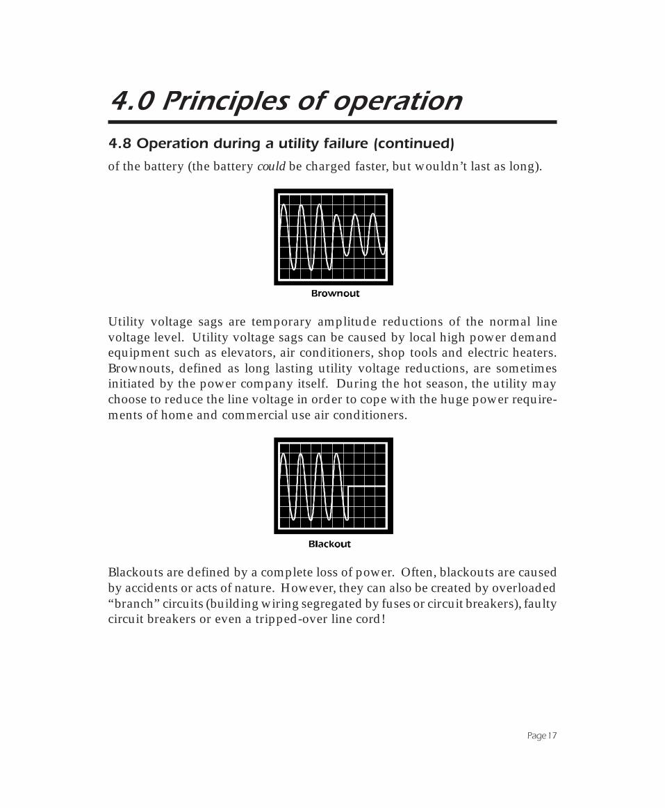
of the battery (the battery could be charged faster, but wouldn’t last as long).
Utility voltage sags are temporary amplitude reductions of the normal linevoltage level. Utility voltage sags can be caused by local high power demandequipment such as elevators, air conditioners, shop tools and electric heaters.Brownouts, defined as long lasting utility voltage reductions, are sometimesinitiated by the power company itself. During the hot season, the utility maychoose to reduce the line voltage in order to cope with the huge power require-ments of home and commercial use air conditioners.
Blackouts are defined by a complete loss of power. Often, blackouts are causedby accidents or acts of nature. However, they can also be created by overloaded“branch” circuits (building wiring segregated by fuses or circuit breakers), faultycircuit breakers or even a tripped-over line cord!

Page 18
5.0 Controls and indicators5.1 Power I/0 switch
The power I/0 switch controls power to the UPS and its outputreceptacles. When the switch is on, the UPS operates and yourcomputer equipment will be powered. When the switch is off,the UPS is de-energized and your equipment is unpowered. Ifyour equipment switches are left on, the entire system can beoperated by using just the power I/0 switch.
Under normal conditions, the lamp within the power I/0 switch illuminateswhenever the UPS is switched on. When the UPS is operating on-battery, thelamp flashes. The lamp will flash, and the UPS will shut down, in the event of aninternal UPS fault.
5.2 Test switch (on units so equipped)
When the Test switch is pressed, the UPS simulates a power outageand transfers your load to the alternate power source. This featureallows you to determine that computer equipment protected bythe UPS operates normally during transfers. It also provides aconvenient means of testing the UPS’s battery. If the Test controlis held depressed, the UPS will operate your equipment from power derivedfrom the battery continuously. If during the test the low battery warning issounded prematurely and the load is known to be normal, then the battery isweak and requires extended recharge or replacement (see section 7.0).
5.3 Audible alarm
During a utility failure, the UPS emits a series of four beeps once every 30 secondsto warn you that your equipment is operating from a source of power which islimited in duration. In the event of an extended utility failure, the UPS will soundcontinuous beeps 2 minutes in advance of shut down due to battery capacityexhaustion. Once shut down, the UPS will cease sounding the alarm. In the eventthe UPS encounters a severe overload, the UPS will shut down and emit a loudtone. The alarm is reset when the UPS is turned off. The UPS will shut down andsound the audible alarm when an internal fault is detected.

Page 19
6.0 UPS monitoring6.1 Overview
A UPS system alone provides excellent protection from brief power problems.However, during an extended power outage an unattended computer systemwill eventually shut down due to battery capacity exhaustion. To prevent datacorruption when the UPS shuts down, the computer must be informed by theUPS of impending shut down and take appropriate file-saving measures. Thisimportant function is called “UPS monitoring.” The UPS’s computer interfaceport is the means by which your UPS communicates with a computer system.
Some computer operating systems have built-in UPS monitoring. These systemsrequire various hardware interfaces. Interface kits for all operating systems thatsupport UPS monitoring are available from your dealer. In addition, your dealeralso offers PowerChute software which enhances such built-in UPS monitoring.Versions of PowerChute are available which add the UPS monitoring function tothe many operating systems which do not inherently provide UPS monitoring.
6.2 Interface Kits
A series of interface kits is available for operating systems that provide UPSmonitoring. Each interface kit includes the special interface cable required toconvert status signals from the UPS into signals which individual operatingsystems recognize. Each kit includes all necessary installation instructions.Systems for which interface kits are offered include Novell, LAN Manager,LANtastic, Banyan VINES and IBM AS/400.
6.3 PowerChute Software
PowerChute software provides complete data protection for most operatingsystems. This software is a background process that monitors the UPS througha RS-232 serial port on the host. PowerChute offers user notification of impend-ing shutdown, power event logging, auto-restart upon power return and UPSbattery conservation features. PowerChute is available for many platformsincluding Novell, LAN Manager, AppleShare, XENIX, most UNIX-based operat-ing systems, and DEC VAX/VMS.
Caution: Use only factory supplied or authorized UPS monitoring cables!
Page 20
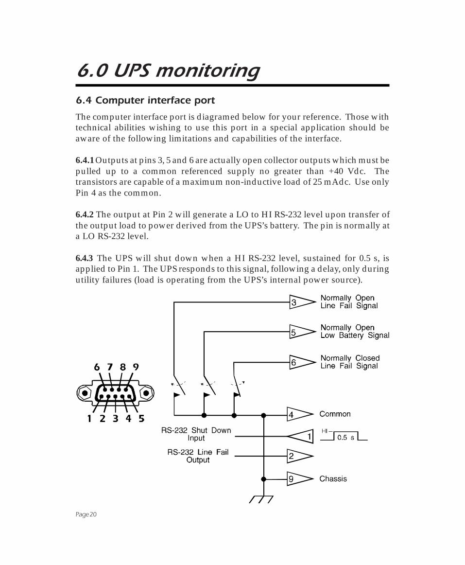
6.0 UPS monitoring6.4 Computer interface port
The computer interface port is diagramed below for your reference. Those withtechnical abilities wishing to use this port in a special application should beaware of the following limitations and capabilities of the interface.
6.4.1 Outputs at pins 3, 5 and 6 are actually open collector outputs which must bepulled up to a common referenced supply no greater than +40 Vdc. Thetransistors are capable of a maximum non-inductive load of 25 mAdc. Use onlyPin 4 as the common.
6.4.2 The output at Pin 2 will generate a LO to HI RS-232 level upon transfer ofthe output load to power derived from the UPS’s battery. The pin is normally ata LO RS-232 level.
6.4.3 The UPS will shut down when a HI RS-232 level, sustained for 0.5 s, isapplied to Pin 1. The UPS responds to this signal, following a delay, only duringutility failures (load is operating from the UPS’s internal power source).

Page 21
7.0 DifficultyCaution !
■ This Uninterruptible Power Source contains potentially hazardous voltages. Donot attempt to disassemble the unit. The unit contains no user serviceable parts.Repairs are performed only by factory trained service personnel.
■ This Uninterruptible Power Source uses batteries. The batteries will eventuallybecome too weak to provide rated autonomous operation. To obtain batteryreplacement or repair service, please call the Customer Service telephone number onthe cover of this manual for information on the Service Center nearest you.
■ The batteries used by this Uninterruptible Power Source are recyclable. Properdisposal of the batteries is required. The batteries contain lead and pose a hazardto the environment and human health if not disposed of properly. Please refer tolocal codes for proper disposal requirements or return the unit to a factoryauthorized Service Center for battery replacement or disposal.
■ Battery replacement should be performed or supervised by personnel familiar withthe danger of batteries and the required precautions. Keep unauthorized personnelaway from batteries. When replacing batteries, use the same number and type ofsealed lead acid batteries as were originally contained in your UPS.
■ CAUTION - Do not dispose of battery in a fire. The batteries may explode.
■ CAUTION - Do not open or mutilate the battery or batteries. They contain anelectrolyte which is toxic and harmful to the skin and eyes.
■ CAUTION - A battery can present a risk of electrical shock and high short circuitcurrent. When replacing batteries, wrist watches and jewelry such as rings should beremoved. Use tools with insulated handles.
ENGLISH

Page 22
FRANÇAIS7.0 DifficultéAttention !
■ Cette source d’alimentation permanente (UPS) contient des circuits haute tensionprésentant un danger. Ne jamais essayer de le démonter. Il n’y a aucun composantqui puisse être réparé par l’utilisateur. Toutes les réparations doivent être effectuéespar du personnel qualifié et agréé par le constructeur.
■ Cette source d’alimentation permanente (UPS) contient des accumulateurs. Cesaccumulateurs deviendront un jour trop faibles pour pouvoir assurer unfonctionnement autonome correct. Pour toute réparation ou remplacement desaccumulateurs, composez le numéro du Service à la clientèle inscrit sur la couverturede ce manuel afin d’obtenir les coordonnées du Centre de Service le plus proche.
■ Les accumulateurs contenus dans cette source d’alimentation sont recyclables.L’elimination des batteries est règlementée. Consulter les codes locaux à cet effet.Ils contiennent du plomb et représentent donc un risque pour l’homme et pourl’environnement si les règles de mise au rebut ne sont pas respectées. Veuillezretournez l’unité à un Centre de Service agréé lorsque vous désirerez remplacer ouvous débarrasser des accumulateurs usagés.
Le remplacement de batterie doit être effectué ou surveillé par du personnel aucourant du danger des batteries et des précautions à prende exigées. Quand vousremplacez les batteries, utilisez le même numéro et le même type de batteries auplomb étanches que celles contenues à l'origine dan votre UPS.
■ ATTENTION - Ne jetez pas les batteries dan un feu. Les batteries peuvent exploser.
■ ATTENTION - N'ouvrez pas ni ne mutilez la batterie ou les batteries. Ellescontiennent un électrolyte qui est toxique et dangereux pour la peau et lex yeux.
■ ATTENTION - Une batterie peut présenter un risque de choc electrique, de brûlurepar transfert d’énergie. Suivre les précautions qui s’imposent. Quand vous replacezdes batteries, il faut retirer les montres-bracelets et la bijouterie comme les bagues.Utilisez des outils ayant des manches isolés.

Page 23
DEUTSCH7.0 SchwierigkeitVorsicht !
■ Im Inneren dieser unterbrechungsfreien Stromversorgung herrschen potentiellgefährliche Spannungen. Nicht versuchen, das Gerät zu öffnen. Es enthält keine vomBenutzer reparierbaren Teile. Reparaturen dürfen nur von ausgebildetemKundendienstpersonal durchgeführt werden.
■ Diese unterbrechungsfreie Stromversorgung enthält Batterien, die nach einerbestimmten Zeit so schwach werden, daß der autonome Nennbetrieb nicht mehrgewährleistet ist. Aufgrund der potentiellen Gesundheits- und Umweltgefahren, dievon den Batterien ausgehen, dürfen sie nur in einem vom Werk autorisiertenKundendienstzentrum ausgewechselt werden. Dort teilt man Ihnen mit, welchesKundendienstzentrum für Sie zuständig ist.
■ Die Batterien in dieser unterbrechungsfreien Stromversorgung sindwiederverwertbar. Sie sind bleihaltig und stellen eine Gefahr für die Umwelt unddie Gesundheit dar, wenn sie nicht ordnungsgemäß entsorgt werden. Das Gerätan ein vom Werk autorisiertes Kundendienstzentrum einsenden, um die Batterienauswechseln oder entsorgen zu lassen.
■ Der Austausch der Batterien sollte von oder unter der Aufsicht von Personendurchgeführt werden, die mit den Gefahren von Batterien und den erforderlichenVorsichtsmaßnahmen vertraut sind. Halten Sie nicht autorisierte Personen von denBatterien fern. Wenn Sie die Batterien ersetzen wollen, verwenden Sie die gleicheAnzahl und den gleichen Typ (geschlossene Bleiakkumulatoren) der ursprünglichmit dem Gerät geliefert wurde.
■ VORSICHT! Werfen Sie die Batterien nicht ins Feuer. Es besteht Explosionsgefahr.
■ VORSICHT! Die Batterien nicht öffnen oder zerstören. Sie enthalten einen giftigenElektroylyten der für Augen und Haut gesundheitsschädlich ist.
■ VORSICHT! Eine Batterie stellt eine Gefahr in bezug auf elektrischen Schlag undhohe Kurzschlusströme dar. Tragen Sie daher keine Armbanduhr oder Ringe, wennSie die Batterien ersetzen. Benutzen Sie Werkzeuge mit isolierten Griffen.

Page 24
ESPAÑOL7.0 Dificultad¡Cuidado!
■ Esta Fuente de energía ininterrumpible contiene niveles de voltaje peligrosos enpotencia. No intente desarmar la unidad, pues no contiene piezas que puedan serreparadas por el usuario. Las reparaciones deben efectuarse únicamente por parte delpersonal de mantenimiento capacitado en la fábrica.
■ Esta Fuente de energía ininterrumpible contiene baterías. Con el tiempo lasbaterías se gastan demasiado para poder sustentar el funcionamiento autónomo a lacapacidad nominal. Para solicitar el reemplazo de baterías o servicio de reparaciones,se ruega llamar al número telefónico de Atención a los Clientes indicado en la tapa deeste manual y averiguar el Centro de Servicio más cercano.
■ Las baterías que se encuentran en esta Fuente de energía ininterrumpible sonreciclables. Las baterías contienen plomo y constituyen un peligro para el medioambiente y para la salud de las personas si no se las desechan como corresponde.Se ruega devolver la unidad a un Centro de Servicio autorizado por la fábrica parael reemplazo o la eliminación de las baterías.
El reemplazo de baterías deberá ser hecho o supervisado por profesionalesfamiliarizados con los daños y precauciones relacionadas con ellas. Mantenga a laspersonas no autorizadas alejadas de las baterías. Cuando cambie las baterías, use delmismo número y tipo de baterías de ácido de plomo selladas que las originales dentrode su fuente ininterrumplible de potencia.
■ ADVERTENCIA - No eche las baterías en el fuego. Pudieran explotar.
■ ADVERTENCIA - No abra o mutile la(s) batería(s). Contienen un electrolito quees tóxico y dañino a la piel y a los ojos.
■ ADVERTENCIA - Las baterías representan un riesgo de impacto eléctrico y dealtas corriente de corto circuito. Cuando reemplace las baterías deberá quitarse todoslos relojes y las joyas tales como anillos. Use herramientas que tengan los mangosaislados.

Page 25
7.0 Difficulty7.1 Troubleshooting chart
PROBLEM POSSIBLE CAUSE ACTION TO TAKE
UPS will not turn on (lamp withinpower I/0 switch is not illuminated),but beeps when power I/0 switchis on.
1. Line cord plug is loose. 1. Check fit of line cord plug.
2. Rear panel circuit breaker istripped.
2. Circuit breaker is tripped whenbutton is extended. Unplugexcessive loads and reset breaker(press button).
3. Dead wall socket. 3. Check wall socket with a tablelamp.
UPS occasionally emits beep,computer equipment operatesnormally.
The UPS is briefly transferring yourequipment to its alternate powersource due to utility voltage sags orspikes.
This operation is normal. The UPSis protecting your computerequipment from abnormal utilityvoltages.
UPS emits beep very often, morethan once or twice an hour.Computer equipment operatesnormally.
Utility voltage is distorted or branchcircuits are heavily loaded.
Have your line voltage checked byan electrician. Operating your UPSfrom an outlet which is wired to adifferent branch fuse or circuitbreaker may help.
UPS does not provide expected runtime. Low battery warning issounded prematurely.
1. Excessive loads connected atUPS’s output receptacles.
1. Unplug excessive loads fromUPS. Recheck computer systempower requirements as describedin installation instructions.
2. Battery is weak due to wear orrecent operation during utility poweroutage.
2. The battery should be rechargedby leaving the UPS plugged in for 6hours - do not operate Test controlduring recharge. If UPS soundslow battery warning prematurelywhen retested, battery should bereplaced.
UPS emits loud tone during utilityfailure. Power I/O switch is on butcomputer equipment is notpowered. Rear panel circuitbreaker is not tripped.
UPS has shut down due tooverload.
Turn off UPS and unplug excessiveloads. Recheck computer systempower requirements as describedin installation instructions. UPS maybe turned on when utility has beenrestored.

Page 26
7.0 Difficulty7.1 Troubleshooting chart (continued)
PROBLEM POSSIBLE CAUSE ACTION TO TAKE
UPS emits loud tone. Power I/0switch is on but computerequipment is not powered. UPS’srear panel circuit breaker is tripped(button is extended). Normal utilityvoltages are known to be present.
UPS has shut down due to severeoverload.
Turn off UPS and unplug excessiveloads. Laser printers will overloadthe UPS and should be plugged intoa quality surge suppressor. Seethe section covering Overloads.Once overload is removed, resetthe circuit breaker (press button).
No UPS output, lamp within powerI/O switch is flashing, UPS emitsconstant beeps. Loads are knownto operate properly.
Internal UPS fault. Remove the UPS from service andcontact Customer Serivce.
UPS beeps continuously. Lampwithin I/0 power switch isilluminated. Utility is not failed.
1. Line cord plug is loose. 1. Check fit of line cord plug.
2. Circuit breaker is tripped. 2. Unplug excessive loads andreset circuit breaker (press button).
UPS does not shut down whenRS-232 HI level is applied tocomputer interface port pin 1.
1. Signal not applied during utilityfailure.
1. The UPS responds to this signalonly during utility failures (load isoperating from the UPS’s internalpower source).
2. Signal is not referenced to UPScommon.
2. Signal must be referenced to theUPS’s common at DB-9F pins 4 or 9.
Low battery warning interval isshorter than 2 minutes.
1. Excessive loads connected atUPS’s output receptacles.
1. Excessive loading may shortenrun time to below 2 minute lowbattery warning interval - removeexcessive loads.
2. Battery capacity low due toconsecutive utility failures.
2. Consecutive utility failures maynot allow time for the battery torecharge thereby causingshortened run time.
Low battery warning interval ismuch longer than 2 minutes.
UPS is loaded to much less than fullrated capacity.
This operation is normal. The lowbattery warning interval is extendedwhen operated under light load.

Page 27
7.0 Difficulty7.2 Replacing the battery
You can expect to receive 3 to 6 years of service life from the UPS's battery wheninstalled in a cool, dry location. If you suspect the battery is weak, allow the UPSto charge the battery for at least 6 hours and perform the Test for properoperation described in section 3.7. If after repeating the test you find that the runtime is still too short, follow the procedures below to replace the battery.
Note: Please read the cautions at the beginning of this section.
7.2.1 Turn off the UPS and unplug it from service. Lay the UPS on its left side andremove the two battery door screws. Remove only the screws indicated on thebattery door.
7.2.2 Gently pull out the battery by grasping the white tab.
7.2.3 Remove the two wires connecting the battery to the UPS. To loosen the wireconnectors, gently wiggle the connectors side-to-side while pulling straight backfrom the mating battery connector.
7.2.4 Connect the battery wires to the new battery. The red wire is positive (+), theblack wire is negative (-).
7.2.5 Position the new battery as shown below and place it into the UPS. Arrangethe wires so that they will not interfere with the battery installation.
7.2.6 Close the battery door and fasten the two battery door screws.
7.2.7 Return the worn battery to the factory for recycling.

Page 28
7.0 Difficulty7.3 Obtaining Service
The troubleshooting chart in section 7.1 covers most of the difficulties that a usermay encounter under conditions other than a failure of the UPS itself. Forproblems not covered in the chart, follow the below listed instructions.
■ See the troubleshooting chart and eliminate the obvious. A tripped UPScircuit breaker is the most common problem encountered and is user reset-table once excessive loads are unplugged from the UPS.
■ If the circuit breaker is OK, note your UPS model, serial number and date ofpurchase. Contact the Customer Service Department at the phone number givenon the cover of this manual.
■ Be prepared to provide a description of the problem. A technician will help yousolve the problem over the phone if possible, or will give you a Return MaterialAuthorization Number (RMA#).
■ If the UPS is within the warranty period, repairs will be performed free ofcharge. If it is not within the warranty period, there will be a charge for repair.
■ Pack the UPS in its original packaging. If you no longer have the originalshipping materials, ask the technician about obtaining a new set. It is veryimportant that you pack the UPS properly to avoid damage in transit. Never usestyrofoam beads for packing because the UPS will settle through beads andbecome damaged. Damages sustained in transit are not covered under warranty.Enclose a letter in the package with your name, RMA#, address, copy of salesreceipt, description of trouble, phone number and check (if necessary).
■ Mark your RMA# on the outside of the package. The factory cannot accept anypackage without this marking.
■ Return your UPS via insured, prepaid carrier to the address on the rear of thisbooklet.

Page 29
8.0 Storing the UPS8.1 Storage conditions
The UPS should be covered and stored in an upright position, in a cool, drylocation. The UPS should be stored with the battery in a fully charged state. Thismeans that the UPS should be allowed to charge the battery for at least 6 hoursbefore the UPS is switched off for storage.
8.2 Extended storage
To achieve expected run time following extended storage, the UPS should beallowed to refresh the battery for 12 hours once every 6 months in environmentswhere the ambient temperature is -15°C to +30°C (5°F to 86°F). For extendedstorage in environments where the ambient temperature is +30°C to +45°C (86°Fto 113°F), the UPS should be allowed to refresh the battery for 12 hours once everymonth.

Page 30
9.0 Run time versus load
Note: Run times are given at 25°C (77°F). Load values given in VA (Volt-Amps).
Load Model250
Model400
Model600
Typical computer load
Q¬��� ���ham s¬¬�ham sTQ�ham �©za4"d��������F�ham"d
�Q��� ¢n�ham �¢�ham s¬Q�ham �"4am�p�^�����¬
s¬¬��� ¢��ham T��ham �n�ham �������¢��¬�§��hpmp4^�phF�hpma�p�
sQ¬��� sT�ham �¬�ham QT�ham �������¢��¬�§a�^�sT�����hpma�p�
¢¬¬��� G�ham sn�ham Ts�ham �������¢�QQ�¨�§a�^�sT�����hpma�p�
¢Q¬��� Q�ham s��ham �s�ham �phz"���G��¢QF�§��sT�����hpma�p�
�¬¬��� n�ham ¢¢�ham �phz"���G�����§��sT�����hpma�p�
�Q¬��� ��ham s��ham �������¢�G¬�OadF��F�¦F�
T¬¬��� Q�ham s��ham �phz"���G�����§��sn�����hpma�p�
TQ¬��� s¬�ham �phz"��TG�����§��sn�����hpma�p�
Q¬¬��� ��ham �phz"���©��Fhz�p��F�¦F�
QQ¬��� ��ham |¢}��phz"���G��¢QF�§�����hpma�p�
�¬¬��� Q�ham |¢}��phz"���G�����§�����hpma�p�

Page 31
10.0 Specifications9.1 Input
Nominal input voltage: single phase 230 Vac.Nominal input frequency: 50 or 60 Hz, selected by microprocessor.
9.2 Transfer Characteristics
Frequency limits for on-line operation: ±5% of the nominal 50 or 60 Hz.Low input voltage limit for on-line operation: 196 Vac.High input voltage limit for on-line operation: 280 Vac.
9.3 Output Characteristics
Maximum load: 250 VA or 170 W, 400 VA or 250 W, and 600 VA or 400 W formodels 250, 400 and 600 respectively.Nominal output voltage: 225 Vac, ±5%. When verifying UPS on-battery outputvoltage, use only a true rms responding voltmeter.Frequency regulation: 50 or 60 Hz, ±3% unless synchronized to the utility.Waveshape: stepped approximation to sine wave; peak and rms values equiva-lent to the utility.Protection: electronically overcurrent and short circuit protected, overloadshutdown is latched.
9.4 Battery and charger
Battery type: maintenance free lead-acid, sealed and leakproof.Typical service life: 3-6 years, dependent on number of discharges, temperature.Low battery signalling: > 2 minute audible tone, interface port signal.Recharge time: 4 to 5 hours, dependent on load and length of utility outage.
9.5 Surge and noise suppression
Surge energy rating: 320 Joules (one time, 10/1000µs waveform).Surge current capability: 6500 Amp peak (one time, 8/20µs waveform).Surge response time: 0 ns (instantaneous) normal mode, <5ns common mode.Noise filter: full time EMI/RFI suppression, 100 kHz to 10 MHz.
9.6 Operating environment and physical dimensions
Operating environment: 0°C - 40°C (32°F - 104°F), 0 to 95% RH, non condensing.Size: 6.6" H x 4.7" W x 14.2" D (17 cm x 12 cm x 36 cm).Weight: 12.1 lb (5.5 kg), 15,4 lb (7.0 kg) and 24.3 lb (11.0 kg) for the UPS models250, 400 and 600 respectively. Add 2 lb (1 kg) for shipping.

Page 32
DECLARATION OF CONFORMITY
Application of Council Directive(s): 89/336/EEC, 73/23/EEC
Standard(s) to which Conformity is Declared: EN55022, EN50082-1
EN50091-1
Manufacturer's Name: AMERICAN POWER CONVERSION
Manufacturer's Address: 132 FAIRGROUNDS ROAD
WEST KINGSTON, RI 02892 USA
Importer's Name:
Importer's Address:
Type of Equipment: UNINTERRUPTIBLE POWER SOURCE
Model No.: BACK-UPS 250, 400, 600
Serial Number: B930100001-B931299999, B940100001-B941299999
Year of Manufacture: 1993, 1994
I, the undersigned, hereby declare that the equipment specified above conformsto the above Directives(s).
Place: BILLERICA, MA USA
(Signature)
Date: 12/1/93 William Burke
(Full name)
Regulatory Compliance Engineer
(Position)

Limited WarrantyAmerican Power Conversion (APC) warrants its products to be free from defects in materialsand workmanship for a period of two years from the date of purchase. Its obligation under thiswarranty is limited to repairing or replacing, at its own sole option, any such defectiveproducts. To obtain service under warranty you must obtain a Returned Material Authoriza-tion (RMA) number from APC or an APC service center. Products must be returned to APCor an APC service center with transportation charges prepaid and must be accompanied by abrief description of the problem encountered and proof of date and place of purchase. Thiswarranty does not apply to equipment which has been damaged by accident, negligence, ormis-application or has been altered or modified in any way. This warranty applies only to theoriginal purchaser who must have properly registered the product within 10 days of purchase.
EXCEPT AS PROVIDED HEREIN, AMERICAN POWER CONVERSION MAKES NO WAR-RANTIES, EXPRESS OR IMPLIED, INCLUDING WARRANTIES OF MERCHANTABILITYAND FITNESS FOR A PARTICULAR PURPOSE. Some states do not permit limitation orexclusion of implied warranties; therefore, the aforesaid limitation(s) or exclusion(s) may notapply to the purchaser.
EXCEPT AS PROVIDED ABOVE, IN NO EVENT WILL APC BE LIABLE FOR DIRECT,INDIRECT, SPECIAL, INCIDENTAL, OR CONSEQUENTIAL DAMAGES ARISING OUT OFTHE USE OF THIS PRODUCT, EVEN IF ADVISED OF THE POSSIBILITY OF SUCH DAM-AGE. Specifically, APC is not liable for any costs, such as lost profits or revenue, loss ofequipment, loss of use of equipment, loss of software, loss of data, costs of substitutes, claimsby third parties, or otherwise. This warranty gives you specific legal rights and you may alsohave other rights which vary from state to state.
Life support policyAs a general policy, American Power Conversion (APC) does not recommend the use of anyof its products in life support applications where failure or malfunction of the APC product canbe reasonably expected to cause failure of the life support device or to significantly affect itssafety or effectiveness. APC does not recommend the use of any of its products in direct patientcare. APC will not knowingly sell its products for use in such applications unless it receives inwriting assurances satisfactory to APC that (a) the risks of injury or damage have beenminimized, (b) the customer assumes all such risks, and (c) the liability of American PowerConversion is adequately protected under the circumstances.
Examples of devices considered to be life support devices are neonatal oxygen analyzers, nervestimulators (whether used for anesthesia, pain relief, or other purposes), autotransfusiondevices, blood pumps, defibrillators, arrhythmia detectors and alarms, pacemakers,hemodialysis systems, peritoneal dialysis systems, neonatal ventilator incubators, ventilatorsfor both adults and infants, anesthesia ventilators, and infusion pumps as well as any otherdevices designated as “critical” by the U.S. FDA.
Hospital grade wiring devices and leakage current may be ordered as options on many APCUPS systems. APC does not claim that units with this modification are certified or listed asHospital Grade by APC or any other organization. Therefore these units do not meet therequirements for use in direct patient care.

990-2013-1 11/93
( PHONE PHONE PHONE PHONE PHONE
(+33) 1.64.62.59.00 in Eur(+33) 1.64.62.59.00 in Eur(+33) 1.64.62.59.00 in Eur(+33) 1.64.62.59.00 in Eur(+33) 1.64.62.59.00 in Europeopeopeopeope(401) 789-5735 world wide(401) 789-5735 world wide(401) 789-5735 world wide(401) 789-5735 world wide(401) 789-5735 world wide
* MAILING MAILING MAILING MAILING MAILING
American Power Conversion4, rue Ste Claire Deville
Zac du Mandinet-Bâtiment EspaceLOGNES
77447 MARNE LA VALLEE Cédex 2FRANCE
( PHONE PHONE PHONE PHONE PHONE
(800) 800-4272 in USA, Canada(800) 800-4272 in USA, Canada(800) 800-4272 in USA, Canada(800) 800-4272 in USA, Canada(800) 800-4272 in USA, Canada(401) 789-5735 world wide(401) 789-5735 world wide(401) 789-5735 world wide(401) 789-5735 world wide(401) 789-5735 world wide
* MAILING MAILING MAILING MAILING MAILING
American Power Conversion132 Fairgrounds Road
P.O. Box 278West Kingston, Rhode Island
02892 USA
Note: The troubleshooting chart in section 7.0 offers solutions for most of the difficultiesyou may encounter with this UPS. Before calling the customer service number,please have available your UPS's serial number (see the label at the rear of theUPS).
Serial number: ___________________________