modelo g. e. | genset model hrfw-100 t5 hrfw-135 t5 … · 52 modelo g. e. | genset model hrfw-100...
TRANSCRIPT
52
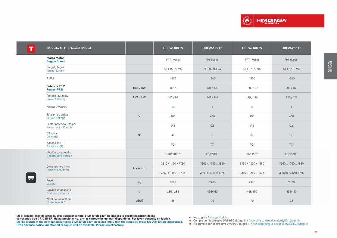
Modelo G. E. | Genset Model HRFW-100 T5 HRFW-135 T5 HRFW-160 T5 HRFW-200 T5
Marca Motor Engine Brand FPT (Iveco) FPT (Iveco) FPT (Iveco) FPT (Iveco)
Modelo Motor Engine Model NEF45 TM 2A NEF67 TM 2A NEF67 TM 3A NEF67 TE 2A
R.P.M. 1500 1500 1500 1500
Potencia P.R.P. Power P.R.P.
kVA / kW 98 / 79 131 / 105 159 / 127 200 / 160
Potencia StandbyPower Standby
kVA / kW 107 / 86 143 / 114 175 / 140 220 / 176
Norma 97/68/EC
Tensión de salidaOutput voltage
V 400 400 400 400
Factor potencia Cos phiPower factor Cos phi 0,8 0,8 0,8 0,8
CilindrosCylindres
Nº 4L 6L 6L 6L
Aspiración (1)Aspiration (1) TCI TCI TCI TCI
Versión constructivaConstructive version D2R/D10R(2) ER/E10R(2) ER/E10R(2) ER/E10R(2)
Dimensiones (mm) Dimensions (mm)
L x W x H
2810 x 1150 x 1780 3360 x 1250 x 1880 3360 x 1250 x 1880 3360 x 1250 x 1880
2850 x 1150 x 1793 3360 x 1250 x 1975 3360 x 1250 x 1975 3360 x 1250 x 1975
PesoWeight
Kg 1800 2280 2325 2370
Capacidad depósitoFuel tank capacity
L 285 / 288 495/450 495/450 495/450
Nivel de ruido @ 7mNoise level @ 7m
dB(A) 66 70 70 72
No exigible / Not applicable Cumple con la directiva 97/68/EC (Stage II) / According to directive 97/68/EC (Stage II) No cumple con la directiva 97/68/EC (Stage II) / Not according to directive 97/68/EC (Stage II)
(2) El lanzamiento de estas nuevas carrocerias tipo B10R-D10R-E10R no implica la descatalogación de las carrocerías tipo CR-D2R-ER. Hasta previo aviso, dichas carrocerías estarán disponibles. Por favor, consulte en fábrica.(2) The launch of the new canopies types B10R-D10R-E10R does not imply that the canopies types CR-D2R-ER are discounted.Until advance notice, mentioned canopies will be available. Please, check factory.
53
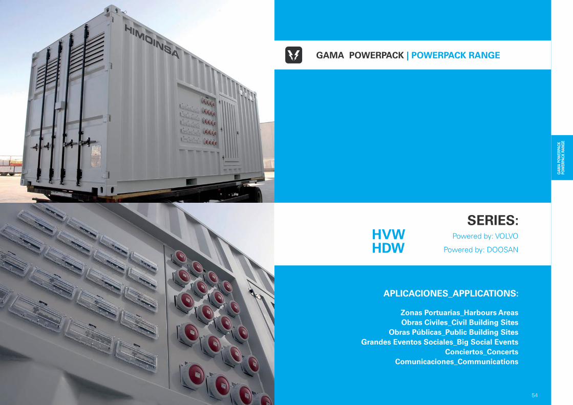
APLICACIONES_APPLICATIONS:
Zonas Portuarias_Harbours AreasObras Civiles_Civil Building Sites
Obras Públicas_Public Building SitesGrandes Eventos Sociales_Big Social Events
Conciertos_ConcertsComunicaciones_Communications
54
GAMA POWERPACK | POWERPACK RANGE
SERIES: Powered by: VOLVO
Powered by: DOOSAN
HVWHDW
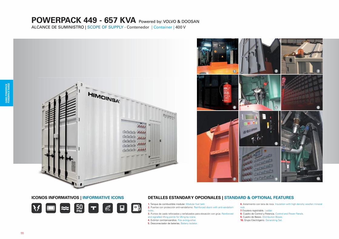
POWERPACK 449 - 657 KVA Powered by: VOLVO & DOOSANALCANCE DE SUMINISTRO | SCOPE OF SUPPLY · Contenedor | Container | 400 V
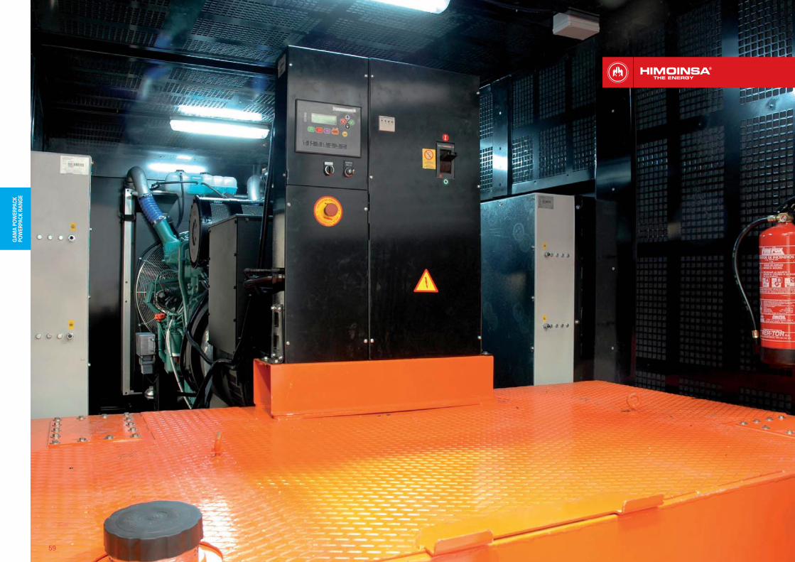
1. Tanque de combustible modular. Modular fuel tank2. Puertas con protección anti-vandalismo. Reinforced doors with anti-vandalism locks.3. Puntos de izado reforzados y señalizados para elevación con grúa. Reinforced and signalled lifting points for lifting by crane.4. Extintor contraincendios. Fire extinguisher.5. Desconectador de baterías. Battery isolator.
6. Aislamiento con lana de roca. Insulation with high density woollen mineral rock.7. Escalera registrable. Ladder.8. Cuadro de Control y Potencia. Control and Power Panels.9. Cuadro de Bases. Distribution Boxes.10. Grupo Electrógeno. Generating Set.
DETALLES ESTANDAR Y OPCIONALES | STANDARD & OPTIONAL FEATURES
2 3
5
7
6
10
8
9
1
4
55
ICONOS INFORMATIVOS | INFORMATIVE ICONS
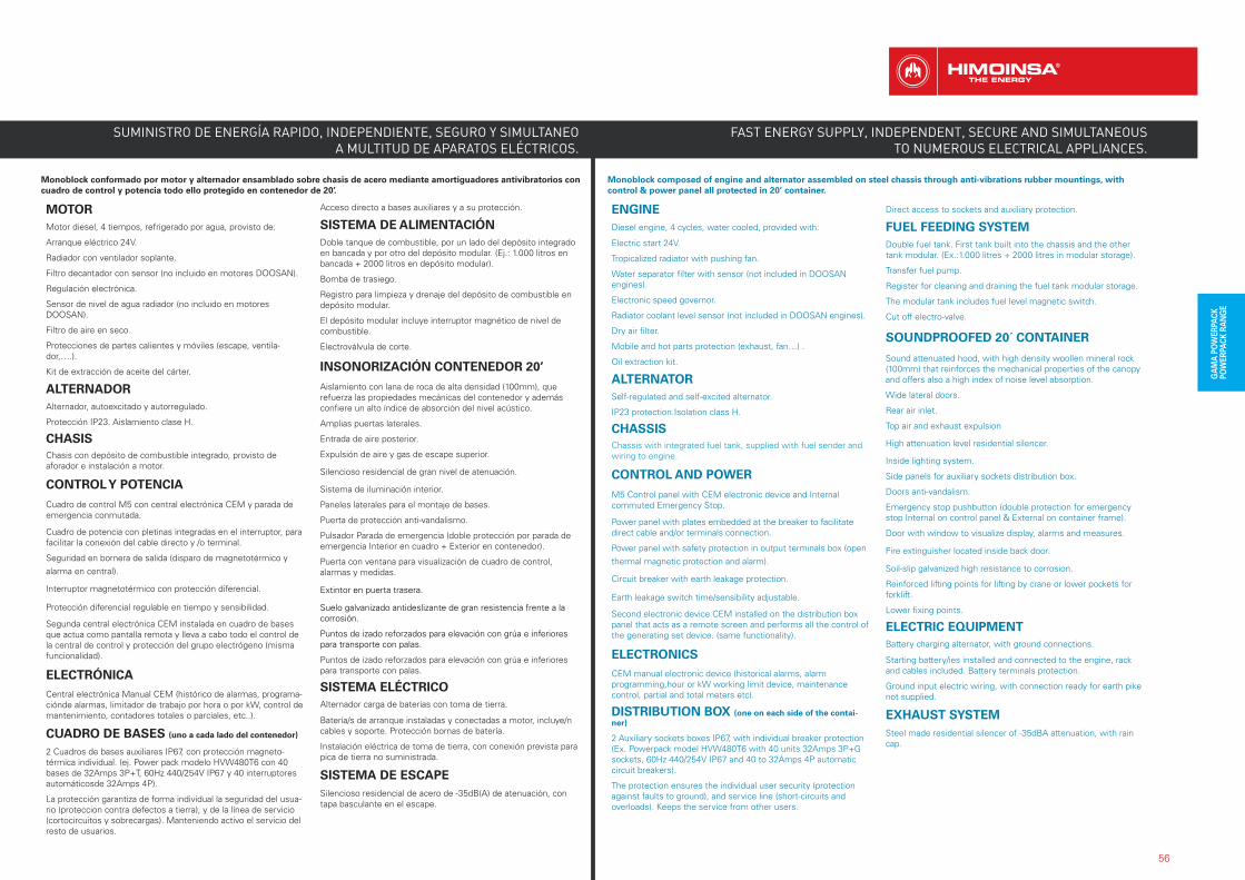
Monoblock conformado por motor y alternador ensamblado sobre chasis de acero mediante amortiguadores antivibratorios con cuadro de control y potencia todo ello protegido en contenedor de 20’.
MOTORMotor diesel, 4 tiempos, refrigerado por agua, provisto de:
Arranque eléctrico 24V.
Radiador con ventilador soplante.
Filtro decantador con sensor (no incluido en motores DOOSAN).
Regulación electrónica.
Sensor de nivel de agua radiador (no incluido en motores DOOSAN).
Filtro de aire en seco.
Protecciones de partes calientes y móviles (escape, ventila-dor,….).
Kit de extracción de aceite del cárter.
ALTERNADORAlternador, autoexcitado y autorregulado.
Protección IP23. Aislamiento clase H.
CHASISChasis con depósito de combustible integrado, provisto de aforador e instalación a motor.
CONTROL Y POTENCIA
Cuadro de control M5 con central electrónica CEM y parada deemergencia conmutada.
Cuadro de potencia con pletinas integradas en el interruptor, para facilitar la conexión del cable directo y /o terminal.
Seguridad en bornera de salida (disparo de magnetotérmico y alarma en central).
Interruptor magnetotérmico con protección diferencial.
Protección diferencial regulable en tiempo y sensibilidad.
Segunda central electrónica CEM instalada en cuadro de bases que actua como pantalla remota y lleva a cabo todo el control de la central de control y protección del grupo electrógeno (misma funcionalidad).
ELECTRÓNICACentral electrónica Manual CEM (histórico de alarmas, programa-ciónde alarmas, limitador de trabajo por hora o por kW, control demantenimiento, contadores totales o parciales, etc..).
CUADRO DE BASES (uno a cada lado del contenedor)
2 Cuadros de bases auxiliares IP67, con protección magneto-térmica individual. (ej. Power pack modelo HVW480T6 con 40 bases de 32Amps 3P+T, 60Hz 440/254V IP67 y 40 interruptores automáticosde 32Amps 4P).
La protección garantiza de forma individual la seguridad del usua-rio (proteccion contra defectos a tierra), y de la línea de servicio (cortocircuitos y sobrecargas). Manteniendo activo el servicio del resto de usuarios.
Acceso directo a bases auxiliares y a su protección.
SISTEMA DE ALIMENTACIÓNDoble tanque de combustible, por un lado del depósito integradoen bancada y por otro del depósito modular. (Ej.: 1.000 litros enbancada + 2000 litros en depósito modular).
Bomba de trasiego.
Registro para limpieza y drenaje del depósito de combustible en depósito modular.
El depósito modular incluye interruptor magnético de nivel de combustible.
Electroválvula de corte.
INSONORIZACIÓN CONTENEDOR 20’
Aislamiento con lana de roca de alta densidad (100mm), que refuerza las propiedades mecánicas del contenedor y además confiere un alto índice de absorción del nivel acústico.
Amplias puertas laterales.
Entrada de aire posterior.
Expulsión de aire y gas de escape superior.
Silencioso residencial de gran nivel de atenuación.
Sistema de iluminación interior.
Paneles laterales para el montaje de bases.
Puerta de protección anti-vandalismo.
Pulsador Parada de emergencia (doble protección por parada deemergencia Interior en cuadro + Exterior en contenedor).
Puerta con ventana para visualización de cuadro de control, alarmas y medidas.
Extintor en puerta trasera.
Suelo galvanizado antideslizante de gran resistencia frente a la corrosión.
Puntos de izado reforzados para elevación con grúa e inferiores para transporte con palas.
Puntos de izado reforzados para elevación con grúa e inferiores para transporte con palas.
SISTEMA ELÉCTRICOAlternador carga de baterías con toma de tierra.
Batería/s de arranque instaladas y conectadas a motor, incluye/n cables y soporte. Protección bornas de batería.
Instalación eléctrica de toma de tierra, con conexión prevista parapica de tierra no suministrada.
SISTEMA DE ESCAPESilencioso residencial de acero de -35dB(A) de atenuación, con tapa basculante en el escape.
Monoblock composed of engine and alternator assembled on steel chassis through anti-vibrations rubber mountings, with control & power panel all protected in 20’ container.
ENGINEDiesel engine, 4 cycles, water cooled, provided with:
Electric start 24V.
Tropicalized radiator with pushing fan.
Water separator filter with sensor (not included in DOOSAN engines).
Electronic speed governor.
Radiator coolant level sensor (not included in DOOSAN engines).
Dry air filter.
Mobile and hot parts protection (exhaust, fan…) .
Oil extraction kit.
ALTERNATORSelf-regulated and self-excited alternator.
IP23 protection.Isolation class H.
CHASSISChassis with integrated fuel tank, supplied with fuel sender and wiring to engine.
CONTROL AND POWER
M5 Control panel with CEM electronic device and Internalcommuted Emergency Stop.
Power panel with plates embedded at the breaker to facilitate direct cable and/or terminals connection.
Power panel with safety protection in output terminals box (openthermal magnetic protection and alarm).
Circuit breaker with earth leakage protection.
Earth leakage switch time/sensibility adjustable.
Second electronic device CEM installed on the distribution box panel that acts as a remote screen and performs all the control of the generating set device. (same functionality).
ELECTRONICSCEM manual electronic device (historical alarms, alarm programming,hour or kW working limit device, maintenance control, partial and total meters etc).
DISTRIBUTION BOX (one on each side of the contai-ner)
2 Auxiliary sockets boxes IP67, with individual breaker protection(Ex. Powerpack model HVW480T6 with 40 units 32Amps 3P+Gsockets, 60Hz 440/254V IP67 and 40 to 32Amps 4P automaticcircuit breakers).
The protection ensures the individual user security (protection against faults to ground), and service line (short-circuits and overloads). Keeps the service from other users.
Direct access to sockets and auxiliary protection.
FUEL FEEDING SYSTEMDouble fuel tank. First tank built into the chassis and the other tank modular. (Ex.:1.000 litres + 2000 litres in modular storage).
Transfer fuel pump.
Register for cleaning and draining the fuel tank modular storage.
The modular tank includes fuel level magnetic switch.
Cut off electro-valve.
SOUNDPROOFED 20´ CONTAINER
Sound attenuated hood, with high density woollen mineral rock(100mm) that reinforces the mechanical properties of the canopyand offers also a high index of noise level absorption.
Wide lateral doors.
Rear air inlet.
Top air and exhaust expulsion
High attenuation level residential silencer.
Inside lighting system.
Side panels for auxiliary sockets distribution box.
Doors anti-vandalism.
Emergency stop pushbutton (double protection for emergency stop Internal on control panel & External on container frame).
Door with window to visualize display, alarms and measures.
Fire extinguisher located inside back door.
Soil-slip galvanized high resistance to corrosion.
Reinforced lifting points for lifting by crane or lower pockets forforklift.
Lower fixing points.
ELECTRIC EQUIPMENTBattery charging alternator, with ground connections.
Starting battery/ies installed and connected to the engine, rack and cables included. Battery terminals protection.
Ground input electric wiring, with connection ready for earth pikenot supplied.
EXHAUST SYSTEMSteel made residential silencer of -35dBA attenuation, with rain cap.
SUMINISTRO DE ENERGÍA RAPIDO, INDEPENDIENTE, SEGURO Y SIMULTANEO A MULTITUD DE APARATOS ELÉCTRICOS.
56
FAST ENERGY SUPPLY, INDEPENDENT, SECURE AND SIMULTANEOUS TO NUMEROUS ELECTRICAL APPLIANCES.
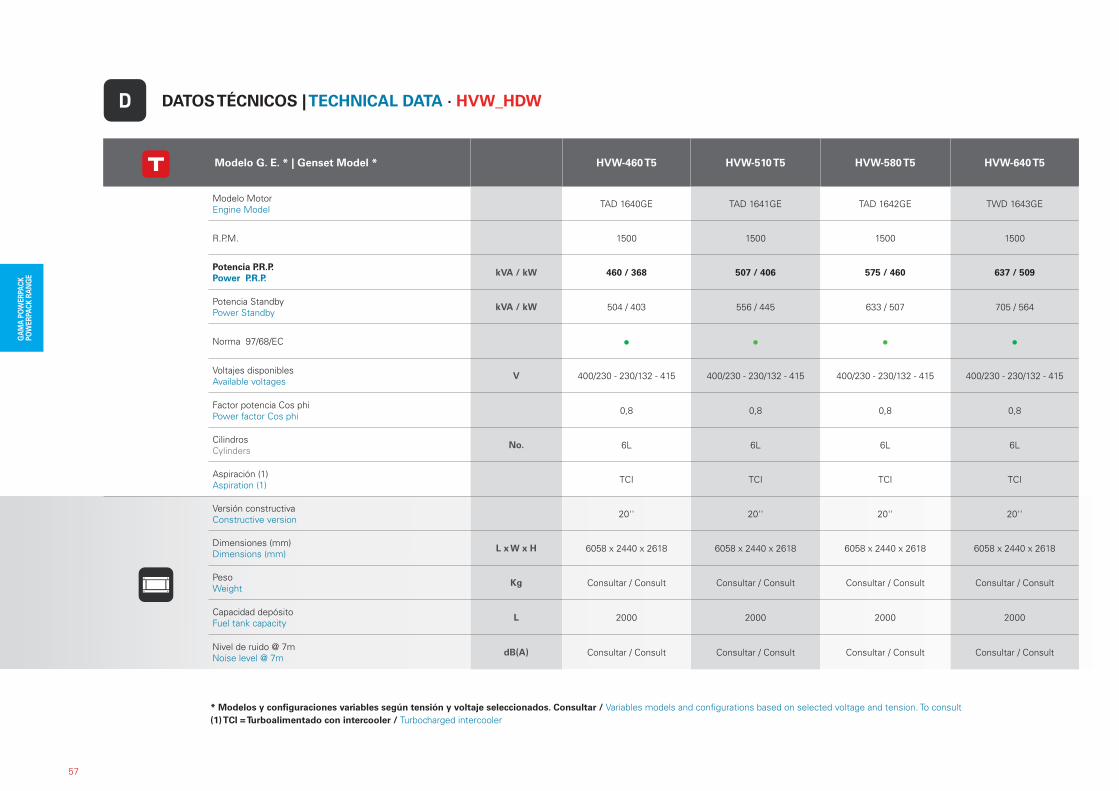
* Modelos y configuraciones variables según tensión y voltaje seleccionados. Consultar / Variables models and configurations based on selected voltage and tension. To consult(1) TCI = Turboalimentado con intercooler / Turbocharged intercooler
57
Modelo G. E. * | Genset Model * HVW-460 T5 HVW-510 T5 HVW-580 T5 HVW-640 T5
Modelo MotorEngine Model TAD 1640GE TAD 1641GE TAD 1642GE TWD 1643GE
R.P.M. 1500 1500 1500 1500
Potencia P.R.P.Power P.R.P.
kVA / kW 460 / 368 507 / 406 575 / 460 637 / 509
Potencia StandbyPower Standby
kVA / kW 504 / 403 556 / 445 633 / 507 705 / 564
Norma 97/68/EC
Voltajes disponiblesAvailable voltages
V 400/230 - 230/132 - 415 400/230 - 230/132 - 415 400/230 - 230/132 - 415 400/230 - 230/132 - 415
Factor potencia Cos phiPower factor Cos phi 0,8 0,8 0,8 0,8
CilindrosCylinders
No. 6L 6L 6L 6L
Aspiración (1)Aspiration (1) TCI TCI TCI TCI
Versión constructivaConstructive version 20'' 20'' 20'' 20''
Dimensiones (mm)Dimensions (mm)
L x W x H 6058 x 2440 x 2618 6058 x 2440 x 2618 6058 x 2440 x 2618 6058 x 2440 x 2618
PesoWeight
Kg Consultar / Consult Consultar / Consult Consultar / Consult Consultar / Consult
Capacidad depósitoFuel tank capacity
L 2000 2000 2000 2000
Nivel de ruido @ 7mNoise level @ 7m
dB(A) Consultar / Consult Consultar / Consult Consultar / Consult Consultar / Consult
DATOS TÉCNICOS | TECHNICAL DATA · HVW_HDWD
58
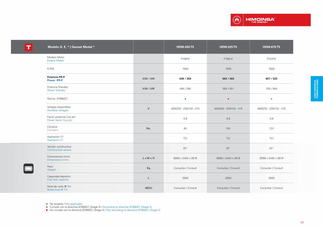
Modelo G. E. * | Genset Model * HDW-450 T5 HDW-525 T5 HDW-670 T5
Modelo MotorEngine Model P158FE P180LE P222FE
R.P.M. 1500 1500 1500
Potencia P.R.P.Power P.R.P.
kVA / kW 449 / 359 503 / 403 657 / 525
Potencia StandbyPower Standby
kVA / kW 494 / 395 564 / 451 705 / 564
Norma 97/68/EC
Voltajes disponiblesAvailable voltages
V 400/230 - 230/132 - 415 400/230 - 230/132 - 415 400/230 - 230/132 - 415
Factor potencia Cos phiPower factor Cos phi 0,8 0,8 0,8
CilindrosCylinders
No. 8V 10V 12V
Aspiración (1)Aspiration (1) TCI TCI TCI
Versión constructivaConstructive version 20'' 20'' 20''
Dimensiones (mm)Dimensions (mm)
L x W x H 6058 x 2440 x 2618 6058 x 2440 x 2618 6058 x 2440 x 2618
PesoWeight
Kg Consultar / Consult Consultar / Consult Consultar / Consult
Capacidad depósitoFuel tank capacity
L 2000 2000 2000
Nivel de ruido @ 7mNoise level @ 7m
dB(A) Consultar / Consult Consultar / Consult Consultar / Consult
No exigible / Not applicable Cumple con la directiva 97/68/EC (Stage II) / According to directive 97/68/EC (Stage II) No cumple con la directiva 97/68/EC (Stage II) / Not according to directive 97/68/EC (Stage II)
59
60
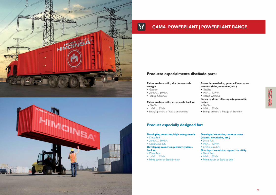
Developing countries; High energy needs• Diesel Fuel
• 20MVA ... 50MVA
• Continuous duty
Developing countries; primary systems back up • Diesel Fuel
• 1MVA ... 5MVA
• Prime power or Stand by duty
Developed countries; remotes areas (islands, mountains, etc.) • Diesel Fuel
• IMVA ... 10MVA
• Continuous duty
Developed countries; support to utility• Diesel fuel;
• IMVA ... 5MVA;
• Prime power or Stand by duty
Product especially designed for:
Paises en desarrollo, alta demanda de energia• Gasóleo
• 20MVA ... 50MVA
• Trabajo Continuo
Paises en desarrollo, sistemas de back up • Gasóleo
• 1MVA ... 5MVA
• Energía primaria o Trabajo en Stand By
Paises desarrollados, generación en areas remotas (islas, montañas, etc.) • Gasóleo
• IMVA ... 10MVA
• Trabajo Continuo
Paises en desarrollo, soporte para utili-dades• Gasóleo;
• IMVA ... 5MVA;
• Energía primaria o Trabajo en Stand By
Producto especialmente diseñado para:
GAMA POWERPLANT | POWERPLANT RANGE
������������ � ������������������������������� ������������
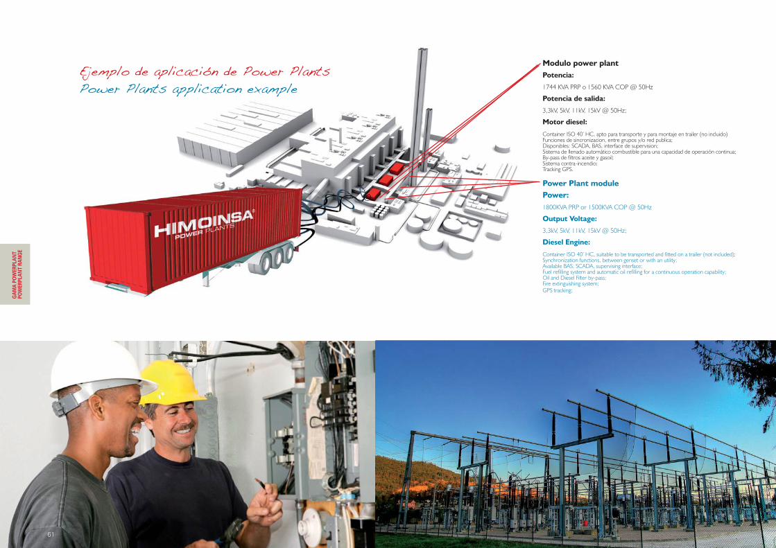
Modulo power plantPotencia:
1744 KVA PRP o 1560 KVA COP @ 50Hz
Potencia de salida:
3,3kV, 5kV, 11kV, 15kV @ 50Hz;
Motor diesel:
Container ISO 40’ HC, apto para transporte y para montaje en trailer (no incluido)Funciones de sincronizacion, entre grupos y/o red publica;Disponibles: SCADA, BAS, interface de supervision;Sistema de llenado automático combustible para una capacidad de operación continua;By-pass de filtros aceite y gasoil;Sistema contra-incendio;Tracking GPS.
Power Plant modulePower:1800KVA PRP or 1500KVA COP @ 50Hz
Output Voltage:
3,3kV, 5kV, 11kV, 15kV @ 50Hz;
Diesel Engine:
Container ISO 40’ HC, suitable to be transported and fitted on a trailer (not included);Synchronization functions, between genset or with an utility;Available BAS, SCADA, supervising interface;Fuel refilling system and automatic oil refilling for a continuous operation capability;Oil and Diesel Filter by-pass;Fire extinguishing system;GPS tracking;
61
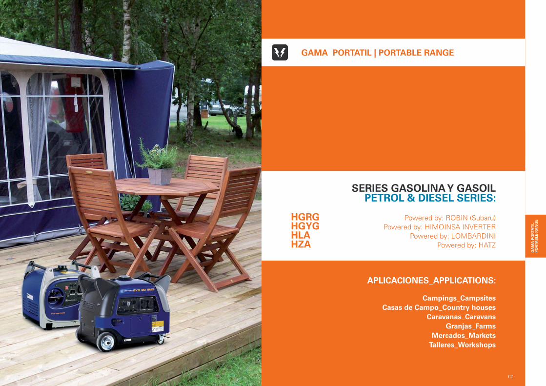
APLICACIONES_APPLICATIONS:
Campings_CampsitesCasas de Campo_Country houses
Caravanas_CaravansGranjas_Farms
Mercados_MarketsTalleres_Workshops
62
GAMA PORTATIL | PORTABLE RANGE
SERIES GASOLINA Y GASOILPETROL & DIESEL SERIES:
Powered by: ROBIN (Subaru)Powered by: HIMOINSA INVERTER
Powered by: LOMBARDINIPowered by: HATZ
HGRGHGYGHLAHZA
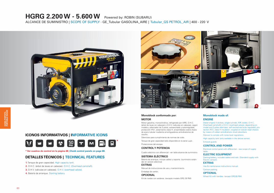
HGRG 2.200 W - 5.600 W Powered by: ROBIN (SUBARU)ALCANCE DE SUMINISTRO | SCOPE OF SUPPLY · GE_Tubular GASOLINA_AIRE | Tubular_GS PETROL_AIR | 400 - 220 V
Monoblock conformado por:
MOTORMotor gasolina, monocilindrico, refrigerado por AIRE, O.H.C. (árbol de levas sin cabezas) o O.H.V. (válvulas en cabezas), según modelo y alternador de 2 polos, autoexcitado y autorregulado, protección IP21, aislamiento clase H, ensamblados sobre chasis de acero tubular mediante amortiguadores antivibratorios de caucho.
Silencioso para cumplimiento de normas de ruido.
Tanque de gran capacidad (sólo disponible en la serie Lujo).
Protecciones del escape.
CONTROL Y POTENCIA
Cuadro eléctrico con diferencial - ver tabla alcance de suministro-.
SISTEMA ELÉCTRICOBatería de arranque, incluye cables y soporte. (suministro están-dar en versión eléctrica)
EXTRASManual de instrucciones de uso y mantenimiento.
Embalaje de cartón.
OPCIONALKit de ruedas con asideras. (excepto modelo GRG 28 RM)
Monoblock made of:
ENGINEDiesel engine 4 strokes, single-cylinder, AIR cooled, O.H.C. (Overhead camshaft) o O.H.V. (overhead valves), depending on model and 2 poles alternator, self excited and auto regulated, pro-tection IP21, class H insulation, coupled on tubular steel chassis by means of rubber antivibrations shock absorbers.
Silencer to comply with noise level regulations.
High capacity tank (only available in the deluxe series).
Exhaust guards.
CONTROL AND POWERElectrical control panel with differential – see scope of supply table-.
ELECTRIC EQUIPMENTStarting battery, includes cables and rack. (Standard supply with Electric version).
EXTRASUse & maintenance instructions manual.
Cartoon packing.
OPTIONALWheel Kit with handles. (except GRG28 RM)
63
1. Tanque de gran capacidad. High capacity tank.
2. O.H.C. (árbol de levas en cabezas). O.H.C. (Overhead camshaft).
3. O.H.V. (válvulas en cabezas). O.H.V. (overhead valves).
4. Batería de arranque. Starting battery.
DETALLES TÉCNICOS | TECHNICAL FEATURES
43
21
ICONOS INFORMATIVOS | INFORMATIVE ICONS
*
* Ver cuadros de control en la página 68_Check control panels on page 68.
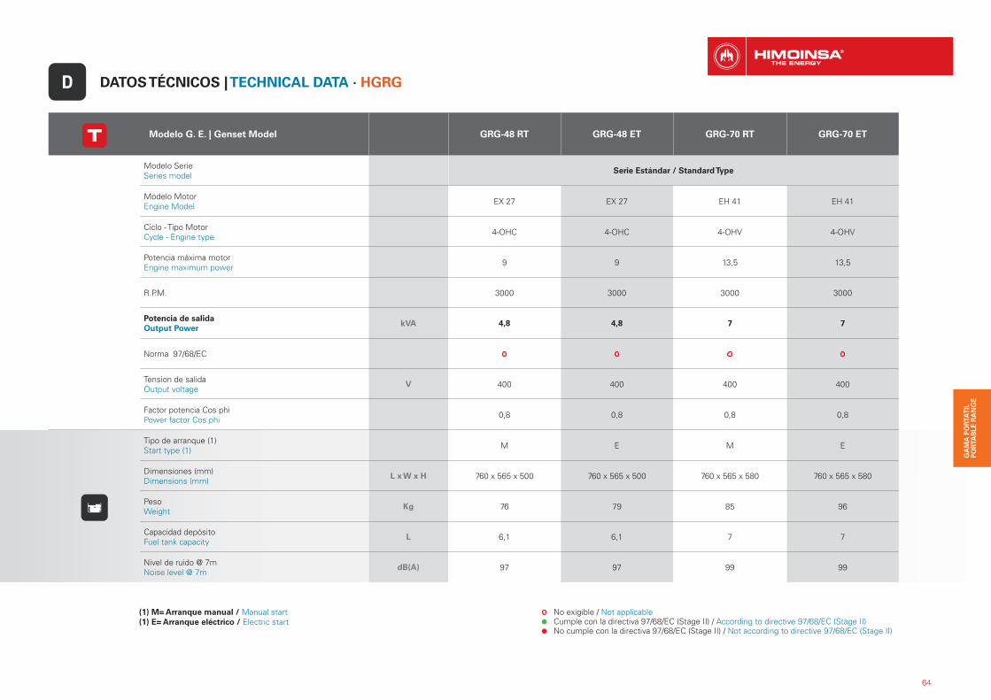
Modelo G. E. | Genset Model GRG-48 RT GRG-48 ET GRG-70 RT GRG-70 ET
Modelo SerieSeries model
Serie Estándar / Standard Type
Modelo MotorEngine Model EX 27 EX 27 EH 41 EH 41
Ciclo - Tipo MotorCycle - Engine type 4-OHC 4-OHC 4-OHV 4-OHV
Potencia máxima motorEngine maximum power 9 9 13,5 13,5
R.P.M. 3000 3000 3000 3000
Potencia de salidaOutput Power
kVA 4,8 4,8 7 7
Norma 97/68/EC
Tension de salidaOutput voltage
V 400 400 400 400
Factor potencia Cos phiPower factor Cos phi 0,8 0,8 0,8 0,8
Tipo de arranque (1)Start type (1) M E M E
Dimensiones (mm)Dimensions (mm)
L x W x H 760 x 565 x 500 760 x 565 x 500 760 x 565 x 580 760 x 565 x 580
PesoWeight
Kg 76 79 85 96
Capacidad depósitoFuel tank capacity
L 6,1 6,1 7 7
Nivel de ruido @ 7mNoise level @ 7m
dB(A) 97 97 99 99
DATOS TÉCNICOS | TECHNICAL DATA · HGRGD
(1) M= Arranque manual / Manual start(1) E= Arranque eléctrico / Electric start
No exigible / Not applicable Cumple con la directiva 97/68/EC (Stage II) / According to directive 97/68/EC (Stage II) No cumple con la directiva 97/68/EC (Stage II) / Not according to directive 97/68/EC (Stage II)
64

65
(1) M= Arranque manual / Manual start(1) E= Arranque eléctrico / Electric start
No exigible / Not applicable Cumple con la directiva 97/68/EC (Stage II) / According to directive 97/68/EC (Stage II) No cumple con la directiva 97/68/EC (Stage II) / Not according to directive 97/68/EC (Stage II)
Modelo G. E. | Genset Model GRG-48 RTL GRG-48 ETL GRG-70 RTL GRG-70 ETL
Modelo SerieSeries model
Serie Lujo / Luxury Type
Modelo MotorEngine Model EX 27 EX 27 EH 41 EH 41
Ciclo - Tipo MotorCycle - Engine type 4-OHC 4-OHC 4-OHV 4-OHV
Potencia máxima motorEngine maximum power 9 9 13,5 13,5
R.P.M. 3000 3000 3000 3000
Potencia de salidaOutput Power
kVA 4,8 4,8 7 7
Norma 97/68/EC
Tension de salidaOutput voltage
V 400 400 400 400
Factor potencia Cos phiPower factor Cos phi 0,8 0,8 0,8 0,8
Tipo de arranque (1)Start type (1) M E M E
Dimensiones (mm)Dimensions (mm)
L x W x H 760 x 565 x 580 760 x 565 x 580 760 x 565 x 580 760 x 565 x 580
PesoWeight
Kg 84 88 97 99
Capacidad depósitoFuel tank capacity
L 26,6 26,6 26,6 26,6
Nivel de ruido @ 7mNoise level @ 7m
dB(A) 97 97 99 99
66
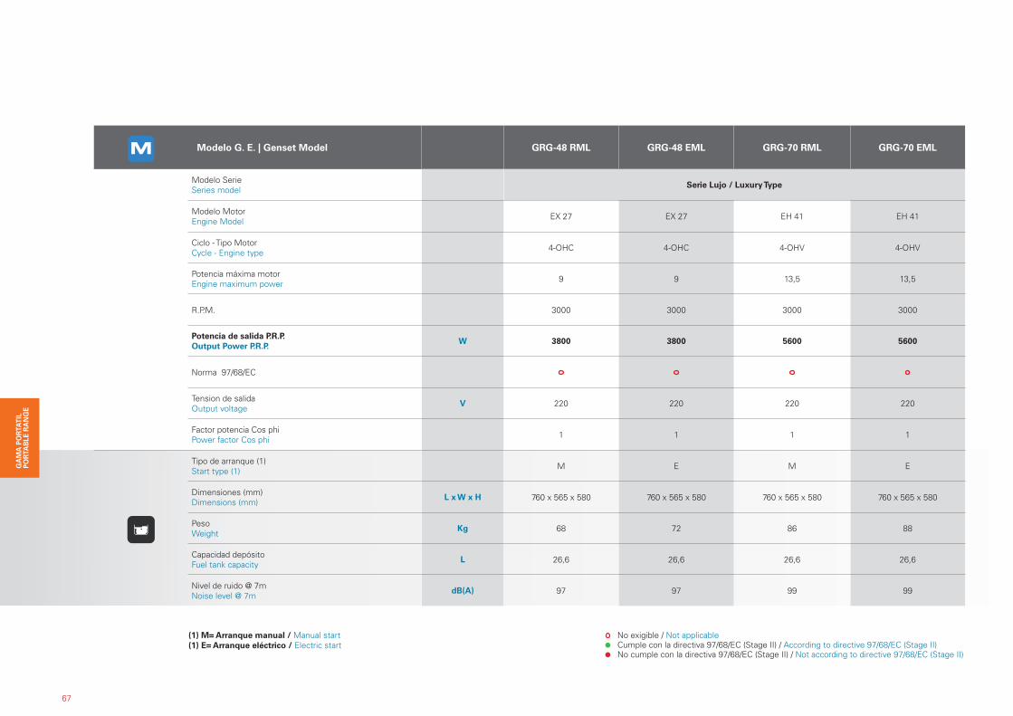
(1) M= Arranque manual / Manual start(1) E= Arranque eléctrico / Electric start
No exigible / Not applicable Cumple con la directiva 97/68/EC (Stage II) / According to directive 97/68/EC (Stage II) No cumple con la directiva 97/68/EC (Stage II) / Not according to directive 97/68/EC (Stage II)
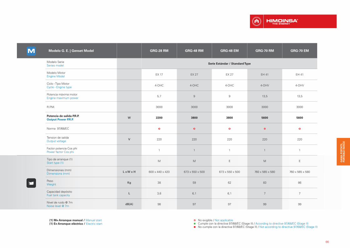
Modelo G. E. | Genset Model GRG-28 RM GRG-48 RM GRG-48 EM GRG-70 RM GRG-70 EM
Modelo SerieSeries model
Serie Estándar / Standard Type
Modelo MotorEngine Model EX 17 EX 27 EX 27 EH 41 EH 41
Ciclo - Tipo MotorCycle - Engine type 4-OHC 4-OHC 4-OHC 4-OHV 4-OHV
Potencia máxima motorEngine maximum power 5,7 9 9 13,5 13,5
R.P.M. 3000 3000 3000 3000 3000
Potencia de salida P.R.P.Output Power P.R.P.
W 2200 3800 3800 5600 5600
Norma 97/68/EC
Tension de salidaOutput voltage
V 220 220 220 220 220
Factor potencia Cos phiPower factor Cos phi 1 1 1 1 1
Tipo de arranque (1)Start type (1) M M E M E
Dimensiones (mm)Dimensions (mm)
L x W x H 600 x 440 x 420 673 x 550 x 500 673 x 550 x 500 760 x 565 x 580 760 x 565 x 580
PesoWeight
Kg 38 59 62 83 86
Capacidad depósitoFuel tank capacity
L 3,6 6,1 6,1 7 7
Nivel de ruido @ 7mNoise level @ 7m
dB(A) 98 97 97 99 99
67
(1) M= Arranque manual / Manual start(1) E= Arranque eléctrico / Electric start
No exigible / Not applicable Cumple con la directiva 97/68/EC (Stage II) / According to directive 97/68/EC (Stage II) No cumple con la directiva 97/68/EC (Stage II) / Not according to directive 97/68/EC (Stage II)
Modelo G. E. | Genset Model GRG-48 RML GRG-48 EML GRG-70 RML GRG-70 EML
Modelo SerieSeries model
Serie Lujo / Luxury Type
Modelo MotorEngine Model EX 27 EX 27 EH 41 EH 41
Ciclo - Tipo MotorCycle - Engine type 4-OHC 4-OHC 4-OHV 4-OHV
Potencia máxima motorEngine maximum power 9 9 13,5 13,5
R.P.M. 3000 3000 3000 3000
Potencia de salida P.R.P.Output Power P.R.P.
W 3800 3800 5600 5600
Norma 97/68/EC
Tension de salidaOutput voltage
V 220 220 220 220
Factor potencia Cos phiPower factor Cos phi 1 1 1 1
Tipo de arranque (1)Start type (1) M E M E
Dimensiones (mm)Dimensions (mm)
L x W x H 760 x 565 x 580 760 x 565 x 580 760 x 565 x 580 760 x 565 x 580
PesoWeight
Kg 68 72 86 88
Capacidad depósitoFuel tank capacity
L 26,6 26,6 26,6 26,6
Nivel de ruido @ 7mNoise level @ 7m
dB(A) 97 97 99 99
68
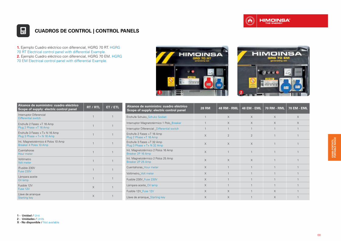
Alcance de suministro: cuadro eléctricoScope of supply: electric control panel
RT / RTL ET / ETL
Interruptor Diferencial Differential switch 1 1
Enchufe 2 Fases +T 16 Amp Plug 2 Phase +T 16 Amp 1 1
Enchufe 3 Fases + T+ N 16 Amp Plug 3 Phase + T+ N 16 Amp 1 1
Int. Magnetotérmico 4 Polos 10 Amp Breaker 4 Poles 10 Amp 1 1
Cuentahoras Hour meter 1 1
Voltímetro Volt meter 1 1
IFusible 230V Fuse 230V 1 1
Lámpara aceite Oil lamp 1 1
Fusible 12V Fuse 12V X 1
Llave de arranque Starting key X 1
Alcance de suministro: cuadro eléctricoScope of supply: electric control panel
28 RM 48 RM - RML 48 EM - EML 70 RM - RML 70 EM - EML
Enchufe Schuko_Schuko Socket 1 X X X X
Interruptor Magnetotérmico 1 Polo_Breaker 1 X X X X
Interruptor Diferencial _Differential switch 1 1 1 1 1
Enchufe 2 Fases +T 16 Amp Plug 2 Phase +T 16 Amp X 2 2 1 1
Enchufe 3 Fases +T 32 AmpPlug 3 Phase + T+ N 32 Amp X X X 1 1
Int. Magnetotérmico 2 Polos 16 Amp Breaker 2P 16 Amp X 1 1 1 1
Int. Magnetotérmico 2 Polos 25 Amp Breaker 2P 25 Amp X X X 1 1
Cuentahoras_Hour meter X 1 1 1 1
Voltímetro_Volt meter X 1 1 1 1
Fusible 230V_Fuse 230V X 1 1 1 1
Lámpara aceite_Oil lamp X 1 1 1 1
Fusible 12V_Fuse 12V X X 1 X 1
Llave de arranque_Starting key X X 1 X 1
1. Ejemplo Cuadro eléctrico con diferencial, HGRG 70 RT. HGRG 70 RT Electrical control panel with differential Example.2. Ejemplo Cuadro eléctrico con diferencial, HGRG 70 EM. HGRG 70 EM Electrical control panel with differential Example.
1 2
CUADROS DE CONTROL | CONTROL PANELS
1 - Unidad / Unit2 - Unidades / UnitsX - No disponible / Not available
3
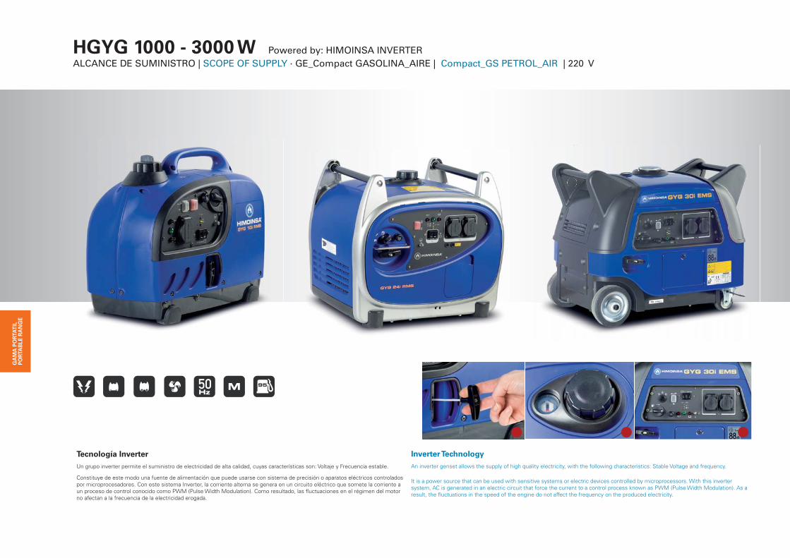
HGYG 1000 - 3000 W Powered by: HIMOINSA INVERTERALCANCE DE SUMINISTRO | SCOPE OF SUPPLY · GE_Compact GASOLINA_AIRE | Compact_GS PETROL_AIR | 220 V
Tecnología InverterUn grupo inverter permite el suministro de electricidad de alta calidad, cuyas características son: Voltaje y Frecuencia estable.
Constituye de este modo una fuente de alimentación que puede usarse con sistema de precisión o aparatos eléctricos controlados por microprocesadores. Con este sistema Inverter, la corriente alterna se genera en un circuito eléctrico que somete la corriente a un proceso de control conocido como PWM (Pulse Width Modulation). Como resultado, las fluctuaciones en el régimen del motor no afectan a la frecuencia de la electricidad erogada.
Inverter TechnologyAn inverter genset allows the supply of high quality electricity, with the following characteristics: Stable Voltage and frequency.
It is a power source that can be used with sensitive systems or electric devices controlled by microprocessors. With this invertersystem, AC is generated in an electric circuit that force the current to a control process known as PWM (Pulse Width Modulation). As a result, the fluctuations in the speed of the engine do not affect the frequency on the produced electricity.
33333333333333333333333333333333333333333333333
70
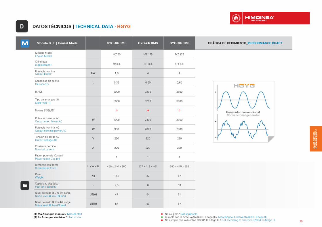
Modelo G. E. | Genset Model GYG-10i RMS GYG-24i RMS GYG-30i EMS GRÁFICA DE REDIMIENTO_PERFORMANCE CHART
Modelo Motor Engine Model MZ 50 MZ 175 MZ 175
CilindradaDisplacement 50 c.c. 171 c.c. 171 c.c.
Potencia nominalOutput power kW 1,6 4 4
Capacidad de aceiteOil capacity
L 0,32 0,60 0,60
R.P.M. 5000 3200 3800
Tipo de arranque (1)Start type (1) 5000 3200 3800
Norma 97/68/EC
Potencia máxima ACOutput max. Power AC
W 1000 2400 3000
Potencia nominal ACOutput nominal power AC
W 900 2000 2800
Tensión de salida ACOutput voltage AC
V 220 220 220
Corriente nominalNominal current
A 220 220 220
Factor potencia Cos phiPower factor Cos phi 1 1 1
Dimensiones (mm) Dimensions (mm)
L x W x H 450 x 240 x 380 527 x 419 x 461 680 x 445 x 555
PesoWeight
Kg 12,7 32 67
Capacidad depósitoFuel tank capacity
L 2,5 6 13
Nivel de ruido @ 7m 1/4 cargaNoise level @ 7m 1/4 load
dB(A) 47 54 51
Nivel de ruido @ 7m 4/4 cargaNoise level @ 7m 4/4 load
dB(A) 57 59 57
DATOS TÉCNICOS | TECHNICAL DATA · HGYGD
(1) M= Arranque manual / Manual start(1) E= Arranque eléctrico / Electric start
No exigible / Not applicable Cumple con la directiva 97/68/EC (Stage II) / According to directive 97/68/EC (Stage II) No cumple con la directiva 97/68/EC (Stage II) / Not according to directive 97/68/EC (Stage II)
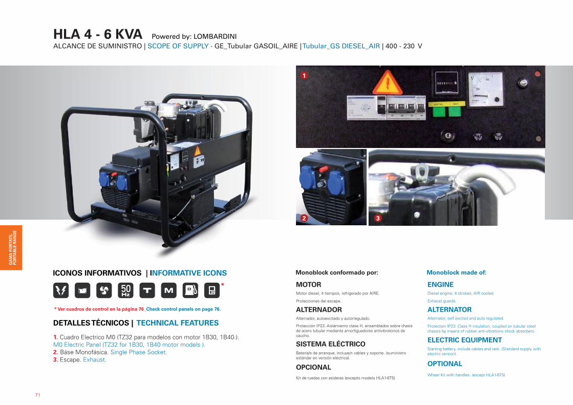
HLA 4 - 6 KVA Powered by: LOMBARDINI ALCANCE DE SUMINISTRO | SCOPE OF SUPPLY · GE_Tubular GASOIL_AIRE | Tubular_GS DIESEL_AIR | 400 - 230 V
Monoblock conformado por:
MOTORMotor diesel, 4 tiempos, refrigerado por AIRE.
Protecciones del escape.
ALTERNADORAlternador, autoexcitado y autorregulado.
Protección IP23. Aislamiento clase H, ensamblados sobre chasis de acero tubular mediante amortiguadores antivibratorios de caucho.
SISTEMA ELÉCTRICOBatería/s de arranque, incluye/n cables y soporte. (suministro estándar en versión eléctrica).
OPCIONALKit de ruedas con asideras (excepto modelo HLA1-6T5)
Monoblock made of:
ENGINEDiesel engine, 4 strokes, AIR cooled.
Exhaust guards.
ALTERNATORAlternator, self excited and auto regulated.
Protection IP23. Class H insulation, coupled on tubular steel chassis by means of rubber anti-vibrations shock absorbers.
ELECTRIC EQUIPMENTStarting battery, include cables and rack. (Standard supply withelectric version).
OPTIONAL
Wheel Kit with handles. (except HLA1-6T5)
1
2 3
71
ICONOS INFORMATIVOS | INFORMATIVE ICONS
1. Cuadro Electrico M0 (TZ32 para modelos con motor 1B30, 1B40.). M0 Electric Panel (TZ32 for 1B30, 1B40 motor models ).2. Báse Monofásica. Single Phase Socket.3. Escape. Exhaust.
DETALLES TÉCNICOS | TECHNICAL FEATURES
*
* Ver cuadros de control en la página 76_Check control panels on page 76.
72
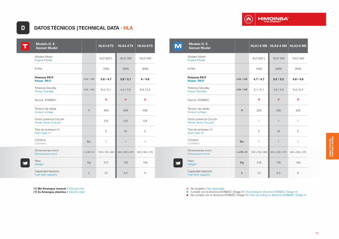
Modelo G. E. Genset Model
HLA1-6 T5 HLA3-4 T5 HLA3-6 T5
Modelo MotorEngine Model 4LD 820 L 15LD 350 15LD 440
R.P.M. 1500 3000 3000
Potencia P.R.P.Power P.R.P.
kVA / kW 5,8 / 4,7 3,9 / 3,1 6 / 4,8
Potencia StandbyPower Standby
kVA / kW 6,4 / 5,1 4,4 / 3,5 6,6 / 5,3
Norma 97/68/EC
Tension de salidaOutput voltage
V 400 400 400
Factor potencia Cos phiPower factor Cos phi 0,8 0,8 0,8
Tipo de arranque (1)Start type (1) E M E
CilindrosCylinders
No. 1 1 1
Dimensiones (mm)Dimensions (mm)
L x W x H 1145 x 740 x 880 800 x 590 x 570 800 x 590 x 570
PesoWeight
Kg 212 125 140
Capacidad depósitoFuel tank capacity
L 7,2 4,3 5
DATOS TÉCNICOS | TECHNICAL DATA · HLAD
(1) M= Arranque manual / Manual start(1) E= Arranque eléctrico / Electric start
No exigible / Not applicable Cumple con la directiva 97/68/EC (Stage II) / According to directive 97/68/EC (Stage II) No cumple con la directiva 97/68/EC (Stage II) / Not according to directive 97/68/EC (Stage II)
Modelo G. E. Genset Model
HLA1-5 M5 HLA3-4 M5 HLA3-6 M5
Modelo MotorEngine Model 4LD 820 L 15LD 350 15LD 440
R.P.M. 1500 3000 3000
Potencia P.R.P.Power P.R.P.
kVA / kW 4,7 / 4,7 3,2 / 3,2 4,8 / 4,8
Potencia StandbyPower Standby
kVA / kW 5,1 / 5,1 3,6 / 3,6 5,4 / 5,4
Norma 97/68/EC
Tension de salidaOutput voltage
V 230 230 230
Factor potencia Cos phiPower factor Cos phi 1 1 1
Tipo de arranque (1)Start type (1) E M E
CilindrosCylinders
No. 1 1 1
Dimensiones (mm)Dimensions (mm)
L x W x H 1145 x 740 x 880 800 x 590 x 570 800 x 590 x 570
PesoWeight
Kg 218 125 140
Capacidad depósitoFuel tank capacity
L 7,2 4,3 5
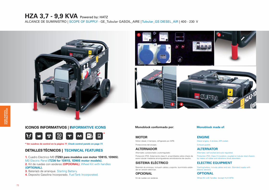
HZA 3,7 - 9,9 KVA Powered by: HATZ ALCANCE DE SUMINISTRO | SCOPE OF SUPPLY · GE_Tubular GASOIL_AIRE | Tubular_GS DIESEL_AIR | 400 - 230 V
Monoblock conformado por:
MOTORMotor diesel, 4 tiempos, refrigerado por AIRE.
Protecciones del escape.
ALTERNADORAlternador, autoexcitado y autorregulado.
Protección IP23. Aislamiento clase H, ensamblados sobre chasis de acero tubular mediante amortiguadores antivibratorios de caucho.
SISTEMA ELÉCTRICOBatería/s de arranque, incluye/n cables y soporte. (suministro están-dar en versión eléctrica).
OPCIONALKit de ruedas con asideras
Monoblock made of:
ENGINEDiesel engine, 4 strokes, AIR cooled.
Exhaust guards.
ALTERNATORAlternator, self excited and auto regulated.
Protection IP23. Class H insulation, coupled on tubular steel chassis by means of rubber anti-vibrations shock absorbers.
ELECTRIC EQUIPMENTStarting battery, include cables and rack. (Standard supply withelectric version).
OPTIONALWheel Kit with handles. (except HLA1-6T5)
1. Cuadro Electrico M0 (TZ63 para modelos con motor 1D81S, 1D90S). M0 Electric Panel (TZ36 for 1D81S, 1D90S motor models).2. Kit de ruedas con asideras (OPCIONAL). Wheel Kit with handles (OPTIONAL).3. Batería/s de arranque. Starting Battery.4. Deposito Gasolina Incorporado. Fuel Tank Incorporated.
73
ICONOS INFORMATIVOS | INFORMATIVE ICONS
DETALLES TÉCNICOS | TECHNICAL FEATURES
1
3 4
2
*
* Ver cuadros de control en la página 77_Check control panels on page 77.
74
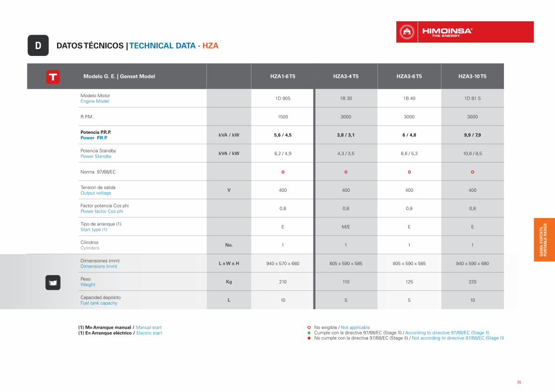
DATOS TÉCNICOS | TECHNICAL DATA · HZAD
Modelo G. E. | Genset Model HZA1-6 T5 HZA3-4 T5 HZA3-6 T5 HZA3-10 T5
Modelo MotorEngine Model 1D 90S 1B 30 1B 40 1D 81 S
R.P.M. 1500 3000 3000 3000
Potencia P.R.P.Power P.R.P.
kVA / kW 5,6 / 4,5 3,8 / 3,1 6 / 4,8 9,9 / 7,9
Potencia StandbyPower Standby
kVA / kW 6,2 / 4,9 4,3 / 3,5 6,6 / 5,3 10,6 / 8,5
Norma 97/68/EC
Tension de salidaOutput voltage
V 400 400 400 400
Factor potencia Cos phiPower factor Cos phi 0,8 0,8 0,8 0,8
Tipo de arranque (1)Start type (1) E M/E E E
CilindrosCylinders
No. 1 1 1 1
Dimensiones (mm)Dimensions (mm)
L x W x H 940 x 570 x 680 805 x 590 x 585 805 x 590 x 585 940 x 590 x 680
PesoWeight
Kg 210 110 125 220
Capacidad depósitoFuel tank capacity
L 10 5 5 10
(1) M= Arranque manual / Manual start(1) E= Arranque eléctrico / Electric start
No exigible / Not applicable Cumple con la directiva 97/68/EC (Stage II) / According to directive 97/68/EC (Stage II) No cumple con la directiva 97/68/EC (Stage II) / Not according to directive 97/68/EC (Stage II)
75
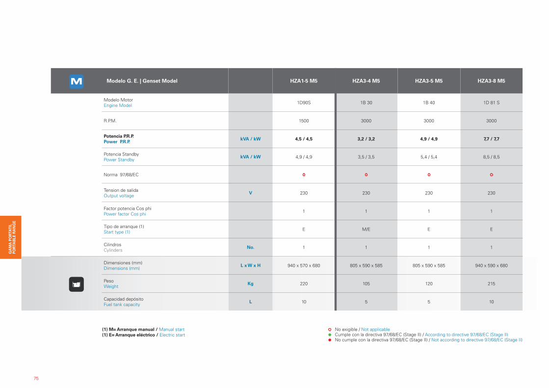
Modelo G. E. | Genset Model HZA1-5 M5 HZA3-4 M5 HZA3-5 M5 HZA3-8 M5
Modelo MotorEngine Model 1D90S 1B 30 1B 40 1D 81 S
R.P.M. 1500 3000 3000 3000
Potencia P.R.P.Power P.R.P.
kVA / kW 4,5 / 4,5 3,2 / 3,2 4,9 / 4,9 7,7 / 7,7
Potencia StandbyPower Standby
kVA / kW 4,9 / 4,9 3,5 / 3,5 5,4 / 5,4 8,5 / 8,5
Norma 97/68/EC
Tension de salidaOutput voltage
V 230 230 230 230
Factor potencia Cos phiPower factor Cos phi 1 1 1 1
Tipo de arranque (1)Start type (1) E M/E E E
CilindrosCylinders
No. 1 1 1 1
Dimensiones (mm)Dimensions (mm)
L x W x H 940 x 570 x 680 805 x 590 x 585 805 x 590 x 585 940 x 590 x 680
PesoWeight
Kg 220 105 120 215
Capacidad depósitoFuel tank capacity
L 10 5 5 10
(1) M= Arranque manual / Manual start(1) E= Arranque eléctrico / Electric start
No exigible / Not applicable Cumple con la directiva 97/68/EC (Stage II) / According to directive 97/68/EC (Stage II) No cumple con la directiva 97/68/EC (Stage II) / Not according to directive 97/68/EC (Stage II)
76
1. Cuadro eléctrico M0 (Modelo Triangular). M0 Electric Panel (Trian-gular Model).2. AC5 cuadro automático por fallo de red. Armario en pared CON conmutación y protección magnetotérmica tetrapolar o bipolar (se-gún tensión y voltaje). Central CEA7. AC5 Automatic mains failure control panel. Wall mounted panel with changeover contactors and thermal magnetic tetra polar protection or bipolar (depending on voltage). Controller CEA7.3. Cuadro Electrico M0 (TZ32 para modelos con motor 15LD350, 15LD440.). M0 Electric Panel (TZ32 for 15LD350, 15LD440 motor models).
21
3
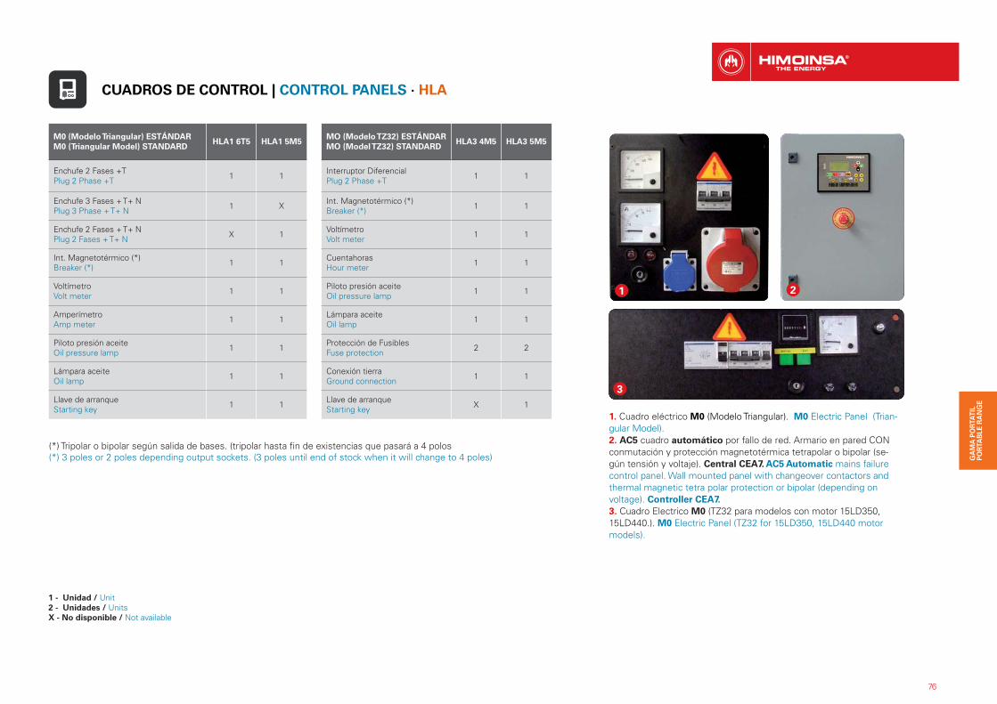
M0 (Modelo Triangular) ESTÁNDAR M0 (Triangular Model) STANDARD
HLA1 6T5 HLA1 5M5
Enchufe 2 Fases +TPlug 2 Phase +T 1 1
Enchufe 3 Fases + T+ NPlug 3 Phase + T+ N 1 X
Enchufe 2 Fases + T+ NPlug 2 Fases + T+ N X 1
Int. Magnetotérmico (*)Breaker (*) 1 1
VoltímetroVolt meter 1 1
Amperímetro Amp meter 1 1
Piloto presión aceiteOil pressure lamp 1 1
Lámpara aceite Oil lamp 1 1
Llave de arranqueStarting key 1 1
MO (Modelo TZ32) ESTÁNDARMO (Model TZ32) STANDARD
HLA3 4M5 HLA3 5M5
Interruptor Diferencial Plug 2 Phase +T 1 1
Int. Magnetotérmico (*)Breaker (*) 1 1
VoltímetroVolt meter 1 1
Cuentahoras Hour meter 1 1
Piloto presión aceiteOil pressure lamp 1 1
Lámpara aceite Oil lamp 1 1
Protección de Fusibles Fuse protection 2 2
Conexión tierraGround connection 1 1
Llave de arranqueStarting key X 1
(*) Tripolar o bipolar según salida de bases. (tripolar hasta fin de existencias que pasará a 4 polos(*) 3 poles or 2 poles depending output sockets. (3 poles until end of stock when it will change to 4 poles)
CUADROS DE CONTROL | CONTROL PANELS · HLA
1 - Unidad / Unit2 - Unidades / UnitsX - No disponible / Not available
77
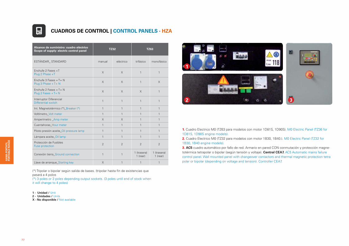
Alcance de suministro: cuadro eléctricoScope of supply: electric control panel TZ32 TZ63
ESTÁNDAR_ STANDARD manual eléctrico trifásico monofásico
Enchufe 2 Fases +TPlug 2 Phase +T X X 1 1
Enchufe 3 Fases + T+ NPlug 3 Phase + T+ N X X 1 X
Enchufe 2 Fases + T+ NPlug 2 Fases + T+ N X X X 1
Interruptor DiferencialDifferential switch 1 1 1 1
Int. Magnetotérmico (*)_Breaker (*) 1 1 1 1
Voltímetro_Volt meter 1 1 1 1
Amperímetro _Amp meter X X 1 1
Cuentahoras_Hour meter 1 1 1 1
Piloto presión aceite_Oil pressure lamp 1 1 1 1
Lámpara aceite_Oil lamp 1 1 1 1
Protección de Fusibles Fuse protection 2 2 2 2
Conexión tierra_Ground connection 1 1 1 (trasera)1 (rear)
1 (trasera)1 (rear)
Llave de arranque_Starting key X 1 1 1
2 3
1
1. Cuadro Electrico M0 (TZ63 para modelos con motor 1D81S, 1D90S). M0 Electric Panel (TZ36 for 1D81S, 1D90S engine models).2. Cuadro Electrico M0 (TZ32 para modelos con motor 1B30, 1B40.). M0 Electric Panel (TZ32 for 1B30, 1B40 engine models).3. AC5 cuadro automático por fallo de red. Armario en pared CON conmutación y protección magne-totérmica tetrapolar o bipolar (según tensión y voltaje). Central CEA7. AC5 Automatic mains failure control panel. Wall mounted panel with changeover contactors and thermal magnetic protection tetra polar or bipolar (depending on voltage and tension). Controller CEA7.
(*) Tripolar o bipolar según salida de bases. (tripolar hasta fin de existencias que pasará a 4 polos(*) 3 poles or 2 poles depending output sockets. (3 poles until end of stock when it will change to 4 poles)
CUADROS DE CONTROL | CONTROL PANELS · HZA
1 - Unidad / Unit2 - Unidades / UnitsX - No disponible / Not available
78
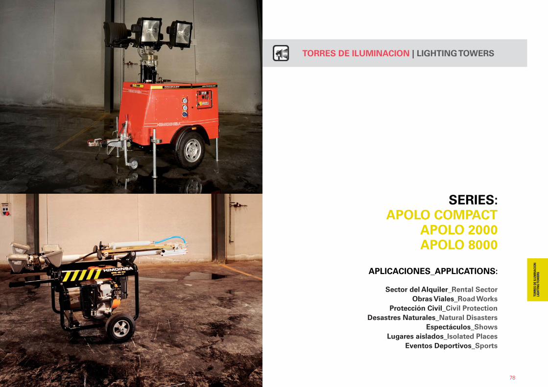
SERIES: APOLO COMPACT
APOLO 2000APOLO 8000
APLICACIONES_APPLICATIONS:
Sector del Alquiler_Rental SectorObras Viales_Road Works
Protección Civil_Civil ProtectionDesastres Naturales_Natural Disasters
Espectáculos_ShowsLugares aislados_Isolated Places
Eventos Deportivos_Sports
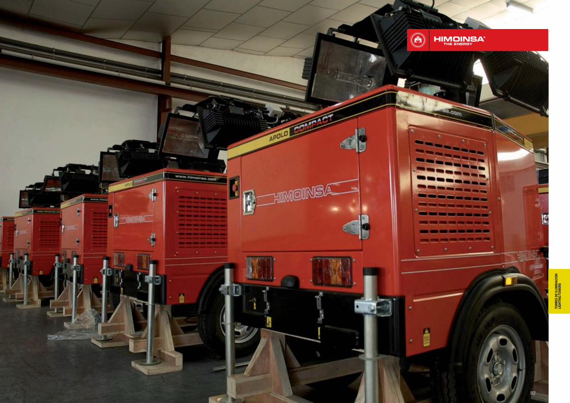
TORRES DE ILUMINACION | LIGHTING TOWERS

APOLO COMPACT � 4000 W_360.000 LUM Powered by: YANMARALCANCE DE SUMINISTRO | SCOPE OF SUPPLY · Torre de Iluminación | Lighting Tower | 230 V
79
1. Mástil telescópico.Telescopic mast. 2. Soporte para 4 Proyectores.Holder for 4 spotlights.3. Grupo Electrógeno insonorizado.Soun-dproof generating set. 4. Cuadro estanco de control.Watertight panel. 5. 2 Enchufes auxiliares de potencia. 2 auxiliary power sockets. 6. 1 entrada auxiliar de alimentación. 1 supply auxiliary entry. 7. Doble Bloqueo de seguridad en mástil.Double safety block in mast.
DETALLES TÉCNICOS TECHNICAL DETAILS
ICONOS INFORMATIVOSINFORMATIVE ICONS
GASOLINAPETROL
DIESEL
CINCUENTA HERZIOSFIFTY HERTZ
TORRES DE ILUMINACIONLIGHTING TOWERS
MONOFASICOSINGLE PHASE
4 FOCOS HALÓGENOS X 1.000 VATIOS CADA UNO. 4 METAL HALIDE LAMPS OF 1.000 WATTS EACH ONE.
ALTURA MÁXIMA: 9 M. MAXIMUM HEIGHT: 9 M.
4.000 VATIOS = 360.000 LÚMENES. 4.000 WATTS = 360.000 LUMENS.
1
2
3
4 5 6 9 10
7 8
12
80
1311
14
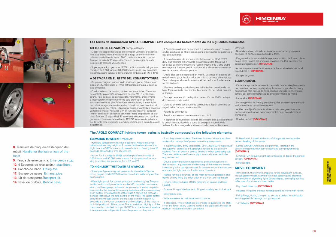
The APOLO COMPACT lighting tower series is basically composed by the following elements:
ELEVATION TOWER KIT made of:· Hydraulic telescopic mast with 9 sections. Reachs automati-cally a total working height of 9 meters. With orientation of the Light beam in 360ºby means of manual rotation. Raising time 13 seconds. Descending time 25 seconds.
· Holder for 4 spotlights (IP65), with lamps of metal-halide of 1.000 watts and 90.000 lumens each. Lamps prepared for wor-king in ambient temperatures from -20 to 45ºC.
TO HIGHLIGHT THE TOWER AS A WHOLE:
· Soundproof generating set, powered by the reliable Yanmar diesel engine model 3TNV76 water cooled and with very low fuel consumption.
· Watertight panel, for control, protection and managing. The pro-tection and control panel includes the M6 controller, hour meter, siren, fuel level gauge, voltmeter, amps meter, thermal magnetic switches for the spotlights, auxiliary sockets and the maneuvering push button; (The maneuver of the mast is carried out through 2 buttons that allows the safe control of the mast. The upper button controls the vertical raise of the mast up to the 9 meter in 13 seconds and the lower button control the collapse of the mast to its initial position in 25 seconds). The up and down highlight of the mast is only controlled through 12V DC from the battery therefore this operation is independent from the power auxiliary entry.
· 2 auxiliary power sockets. The tower has two 16 amps auxiliary sockets for the supply of power to auxiliary equipments.
· 1 supply auxiliary entry (male base, 2P+T, 230V, 32A) that allows the supply of current to the spotlights (and/or to the auxiliary sockets) from an external source (mains or other generating set). The tower willoperate if we supply it externally, even with the engine stopped.
· Double safety block by mast blocking and safety position for the transport. It guarantees the blocking of the mast and avoids involuntary spins during transport. To be able to turn the mast and orientate the light beam is fundamental its unlock.
· Handle for the lock-unlock of the mast in working position. This handle allows fixing the orientation of the mast during the job.
· Liquids retention basin. (120% retention of engine and tank liquids).
· External filling of the fuel tank. Plug with safety lock in fuel tank.
· Emergency stop.
· Wide accesses for maintenance and control.
· 4 stabilizers, two of which are extensible to guarantee the stabi-lity of the tower in any working surface. It suppresses the risk of overturn in adverse ambient conditions.
· Bubble Level, located at the top of the genset to ensure the perfect leveling of the tower.
· Lamps ON/OFF Automatic programmer, located in the back of the genset with easy access and easy programming. (OPTIONAL)
· START/STOP through a light sensor located on top of the genset canopy. (OPTIONAL)
· Exhaust pipe.
MOVIL EQUIPMENT· Transport kit, the tower is prepared for its movement in roads, include jockey wheel, draw bar with ball coupling and electrical connections for signalling lights (brakes lights, turning lights) thus reflectors of position and hand brake.
· High fixed draw bar. (OPTIONAL)
· Includes lifting eye and rear forklift pockets to move with forklift.
· Fixing Rings, during transport to ensure a perfect inmobilization avoiding possible damage during transport.
· 14” Wheels. (OPTIONAL)
8. Manivela de bloqueo-desbloqueo del mástil.Handle for the lock-unlock of the mast. 9. Parada de emergencia. Emergency stop. 10. 4 Soportes de nivelación.4 stabilizers..11. Gancho de izado. Lifting eye 12. Escape de gases. Exhaust pipe. 13. Kit de transporte.Transport kit. 14. Nivel de burbuja. Bubble Level.
Las torres de iluminación APOLO COMPACT está compuesta básicamente de los siguientes elementos:
KIT TORRE DE ELEVACIÓN compuesto por:· Mástil telescópico hidráulico de elevación vertical y 9 expansio-nes, que alcanza una altura total de trabajo de 9 metros y con orientación del haz de luz en 360º, mediante rotación manual. Tiempo de subida 13 segundos. Tiempo de recogida hasta la posición de bloqueo 25 segundos.
· Soporte para 4 proyectores (IP65) con lámparas de halogenuro metálico de 1.000 vatios y 90.000 lúmenes cada una. Lámparas preparadas para trabajar a temperaturas ambiente de -20 a 45ºC.
A DESTACAR EN EL RESTO DEL CONJUNTO TORRE:· Grupo electrógeno insonorizado accionado por el fiable motor diesel YANMAR modelo 3TNV76 refrigerado por agua y de muy bajo consumo. · Cuadro estanco de control, protección y maniobra. El cuadro de control y protección incorpora la central M6, cuenta-horas, sirena, reloj de nivel de combustible, voltímetro, amperímetro e interruptores magnetotérmicos para protección de focos y enchufes auxiliares ylos Pulsadores de maniobra; (La maniobra del mástil se ejecuta mediante dos pulsadores que permiten el control seguro del mástil. El pulsador superior controla el ascenso vertical del mástil hasta los 9 m en 13 segundos y el pulsador inferior controla el descenso del mástil hasta su posición de blo-queo final en 25 segundos). El ascenso y descenso del mástil es gobernado únicamente mediante 12V DC tomados de la batería, por lo tanto esta operación es independiente de la entrada auxiliar de potencia.
· 2 Enchufes auxiliares de potencia. La torre cuenta con dos en-chufes auxiliares de 16 amperios, para el suministro de potencia a equipos auxiliares.
· 1 entrada auxiliar de alimentación (base macho, 2P+T, 230V, 32A) que permite el suministro de corriente a los focos (y/o a las bases auxiliares) desde una fuente externa (red u otro grupo electrógeno). La torre podrá funcionar si la alimentamos externa-mente, aun con el motor parado.
· Doble Bloqueo de seguridad en mástil. Garantiza el bloqueo del mástil y evita giros involuntarios del mismo durante el transporte. Para poder girar el mástil y orientar el haz de luz es fundamental su desbloqueo.
· Manivela de bloqueo-desbloqueo del mástil en posición de tra-bajo. Esta manivela permite fijar la orientación del mástil durante el trabajo.
· Bandeja de retención de líquidos. (retención del 120% de líqui-dos de motor y depósito).
· Llenado externo del tanque de combustible. Tapón con llave de seguridad en tanque de combustible.
· Parada de emergencia. · Amplios accesos al mantenimiento y control.
· 4 soportes de nivelación, dos de ellos extensibles para garantizar la perfecta estabilidad de la torre en cualquier superficie de trabajo. Anula el riesgo de vuelco en condiciones ambientales
adversas.· Nivel de burbuja, ubicado en la parte superior del grupo para asegurar la perfecta nivelación de la torre.
· Programador de encendido/apagado automático de focos, ubica-do en parte trasera del grupo electrógeno con fácil acceso y de sencilla programación. (OPCIONAL)
· Arranque-parada mediante sensor de luz en el exterior sobre el capot del G.E. (OPCIONAL)
· Escape de gases.
EQUIPO MÓVIL
· Kit de transporte, la torre está preparada para su desplazamiento por carretera, incluye rueda jockey, lanza con enganche de bola y conexiones para pilotos de señalización (luces de freno, intermi-tentes) así como reflectantes de posición y freno de mano.
· Lanza alta. (OPCIONAL)
· Incluye gancho de izado y porta-horquillas en trasera para movili-zación mediante carretilla elevadora.
· Anillas para fijación durante el transporte que garantizan una perfecta inmovilización evitando posibles deterioros durante el transporte.
· Ruedas de 14 “. (OPCIONAL)
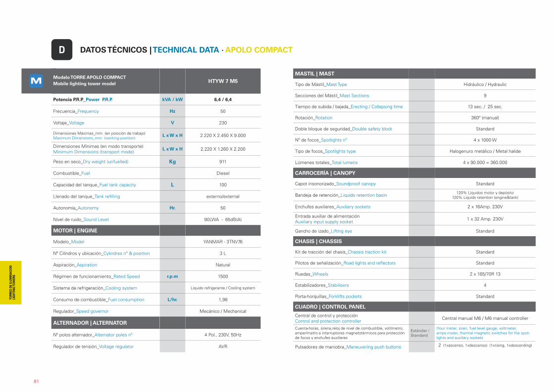
Modelo TORRE APOLO COMPACTMobile lighting tower model HTYW 7 M5
Potencia P.R.P._Power P.R.P. kVA / kW 6,4 / 6,4
Frecuencia_Frequency Hz 50
Voltaje_Voltage V 230
Dimensiones Máximas_mm. (en posición de trabajo) Maximum Dimensions_mm. (working position)
L x W x H 2.220 X 2.450 X 9.000
Dimensiones Mínimas (en modo transporte)Minimum Dimensions (transport mode)
L x W x H 2.220 X 1.260 X 2.200
Peso en seco_Dry weight (unfuelled) Kg 911
Combustible_Fuel Diesel
Capacidad del tanque_Fuel tank capacity L 100
Llenado del tanque_Tank refilling externo/external
Autonomía_Autonomy Hr. 50
Nivel de ruido_Sound Level 90LWA - 65dB(A)
MOTOR | ENGINE
Modelo_Model YANMAR - 3TNV76
Nº Cilindros y ubicación_Cylindres nº & position 3 L
Aspiración_Aspiration Natural
Régimen de funcionamiento_Rated Speed r.p.m 1500
Sistema de refrigeración_Cooling system Líquido refrigerante / Cooling system
Consumo de combustible_Fuel consumption L/hr. 1,98
Regulador_Speed governor Mecánico / Mechanical
ALTERNADOR | ALTERNATOR
Nº polos alternador_Alternator poles nº 4 Pol., 230V, 50Hz
Regulador de tensión_Voltage regulator AVR
MASTIL | MAST
Tipo de Mástil_Mast Type Hidráulico / Hydraulic
Secciones del Mástil_Mast Sections 9
Tiempo de subida / bajada_Erecting / Collapsing time 13 sec. / 25 sec.
Rotación_Rotation 360º (manual)
Doble bloque de seguridad_Double safety block Standard
Nº de focos_Spotlights nº 4 x 1000 W
Tipo de focos_Spotlights type Halogenuro metálico / Metal halide
Lúmenes totales_Total lumens 4 x 90.000 = 360.000
CARROCERÍA | CANOPY
Capot insonorizado_Soundproof canopy Standard
Bandeja de retención_Liquids retention basin 120% Líquidos motor y depósito120% Liquids retention (engine&tank)
Enchufes auxiliares_Auxiliary sockets 2 x 16Amp. 230V
Entrada auxiliar de alimentaciónAuxiliary input supply socket 1 x 32 Amp. 230V
Gancho de izado_Lifting eye Standard
CHASIS | CHASSIS
Kit de tracción del chasis_Chassis traction kit Standard
Pilotos de señalización_Road lights and reflectors Standard
Ruedas_Wheels 2 x 185/70R 13
Estabilizadores_Stabilisers 4
Porta-horquillas_Forklifts pockets Standard
CUADRO | CONTROL PANEL
Central de control y protecciónControl and protection controller Central manual M6 / M6 manual controller
Cuenta-horas, sirena,reloj de nivel de combustible, voltímetro, amperímetro e interruptores magnetotérmicos para protección de focos y enchufes auxiliares
Estándar / Standard
Hour meter, siren, fuel level gauge, voltmeter, amps meter, thermal magnetic switches for the spot-lights and auxiliary sockets
Pulsadores de maniobra_Maneuvering push buttons 2 (1xascenso, 1xdescenso) (1xrising, 1xdescending)
81
DATOS TÉCNICOS | TECHNICAL DATA · APOLO COMPACTD
82
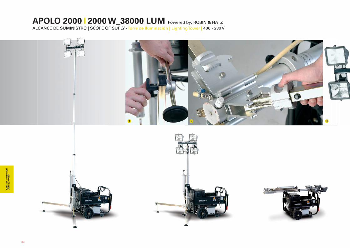
APOLO 2000 �� 2000 W_38000 LUM Powered by: ROBIN & HATZALCANCE DE SUMINISTRO | SCOPE OF SUPLY · Torre de Iluminación | Lighting Tower | 400 - 230 V
1 2 3
83
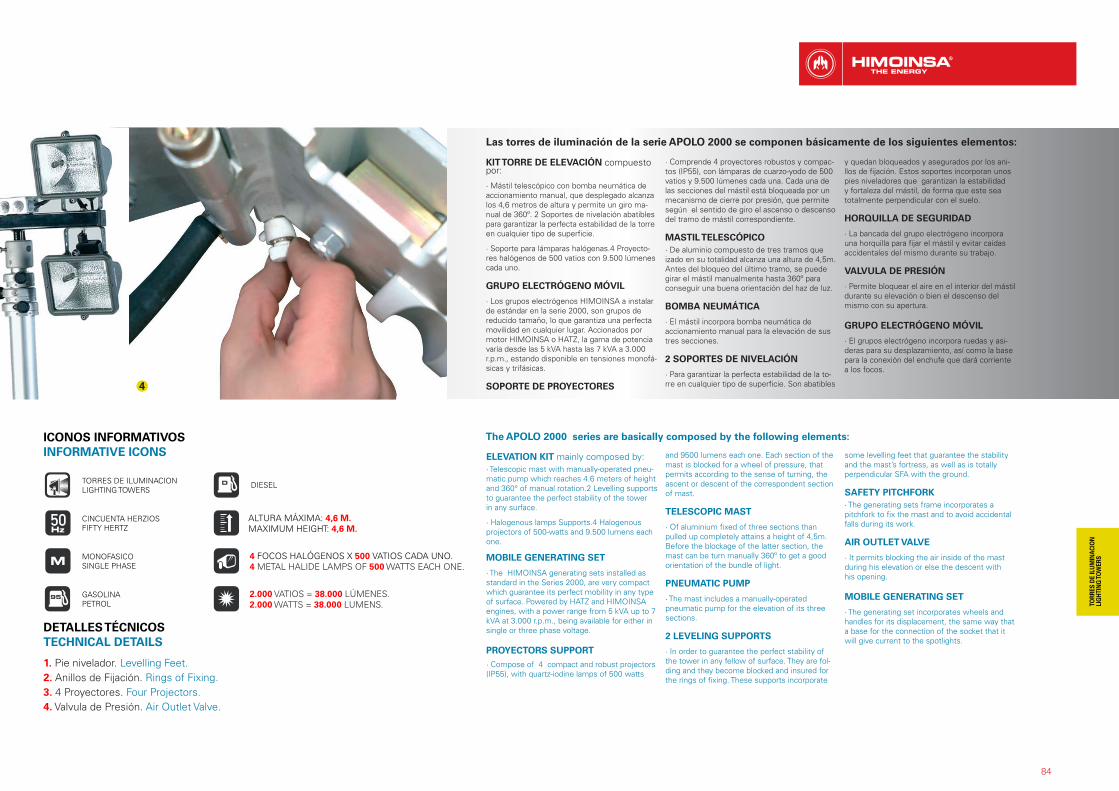
1. Pie nivelador. Levelling Feet. 2. Anillos de Fijación. Rings of Fixing.3. 4 Proyectores. Four Projectors.4. Valvula de Presión. Air Outlet Valve.
4
84
Las torres de iluminación de la serie APOLO 2000 se componen básicamente de los siguientes elementos:
KIT TORRE DE ELEVACIÓN compuesto por:
· Mástil telescópico con bomba neumática de accionamiento manual, que desplegado alcanza los 4,6 metros de altura y permite un giro ma-nual de 360º. 2 Soportes de nivelación abatibles para garantizar la perfecta estabilidad de la torre en cualquier tipo de superficie.
· Soporte para lámparas halógenas.4 Proyecto-res halógenos de 500 vatios con 9.500 lúmenes cada uno. GRUPO ELECTRÓGENO MÓVIL
· Los grupos electrógenos HIMOINSA a instalar de estándar en la serie 2000, son grupos de reducido tamaño, lo que garantiza una perfecta movilidad en cualquier lugar. Accionados por motor HIMOINSA o HATZ, la gama de potencia varía desde las 5 kVA hasta las 7 kVA a 3.000 r.p.m., estando disponible en tensiones monofá-sicas y trifásicas.
SOPORTE DE PROYECTORES
· Comprende 4 proyectores robustos y compac-tos (IP55), con lámparas de cuarzo-yodo de 500 vatios y 9.500 lúmenes cada una. Cada una de las secciones del mástil está bloqueada por un mecanismo de cierre por presión, que permite según el sentido de giro el ascenso o descenso del tramo de mástil correspondiente.
MASTIL TELESCÓPICO· De aluminio compuesto de tres tramos que izado en su totalidad alcanza una altura de 4,5m. Antes del bloqueo del último tramo, se puede girar el mástil manualmente hasta 360º para conseguir una buena orientación del haz de luz.
BOMBA NEUMÁTICA
· El mástil incorpora bomba neumática de accionamiento manual para la elevación de sus tres secciones.
2 SOPORTES DE NIVELACIÓN
· Para garantizar la perfecta estabilidad de la to-rre en cualquier tipo de superficie. Son abatibles
y quedan bloqueados y asegurados por los ani-llos de fijación. Estos soportes incorporan unos pies niveladores que garantizan la estabilidad y fortaleza del mástil, de forma que este sea totalmente perpendicular con el suelo.
HORQUILLA DE SEGURIDAD
· La bancada del grupo electrógeno incorpora una horquilla para fijar el mástil y evitar caídas accidentales del mismo durante su trabajo.
VALVULA DE PRESIÓN
· Permite bloquear el aire en el interior del mástil durante su elevación o bien el descenso del mismo con su apertura.
GRUPO ELECTRÓGENO MÓVIL
· El grupos electrógeno incorpora ruedas y asi-deras para su desplazamiento, así como la base para la conexión del enchufe que dará corriente a los focos.
ICONOS INFORMATIVOSINFORMATIVE ICONS
GASOLINAPETROL
DIESEL
CINCUENTA HERZIOSFIFTY HERTZ
TORRES DE ILUMINACIONLIGHTING TOWERS
MONOFASICOSINGLE PHASE
4 FOCOS HALÓGENOS X 500 VATIOS CADA UNO. 4 METAL HALIDE LAMPS OF 500 WATTS EACH ONE.
ALTURA MÁXIMA: 4,6 M. MAXIMUM HEIGHT: 4,6 M.
2.000 VATIOS = 38.000 LÚMENES. 2.000 WATTS = 38.000 LUMENS.
The APOLO 2000 series are basically composed by the following elements:
ELEVATION KIT mainly composed by: · Telescopic mast with manually-operated pneu-matic pump which reaches 4.6 meters of height and 360° of manual rotation.2 Levelling supports to guarantee the perfect stability of the tower in any surface.
· Halogenous lamps Supports.4 Halogenous projectors of 500-watts and 9.500 lumens each one. MOBILE GENERATING SET
· The HIMOINSA generating sets installed as standard in the Series 2000, are very compact which guarantee its perfect mobility in any type of surface. Powered by HATZ and HIMOINSA engines, with a power range from 5 kVA up to 7 kVA at 3.000 r.p.m., being available for either in single or three phase voltage.
PROYECTORS SUPPORT· Compose of 4 compact and robust projectors (IP55), with quartz-iodine lamps of 500 watts
and 9500 lumens each one. Each section of the mast is blocked for a wheel of pressure, that permits according to the sense of turning, the ascent or descent of the correspondent section of mast.
TELESCOPIC MAST
· Of aluminium fixed of three sections than pulled up completely attains a height of 4,5m. Before the blockage of the latter section, the mast can be turn manually 360º to get a good orientation of the bundle of light.
PNEUMATIC PUMP
· The mast includes a manually-operated pneumatic pump for the elevation of its three sections.
2 LEVELING SUPPORTS
· In order to guarantee the perfect stability of the tower in any fellow of surface. They are fol-ding and they become blocked and insured for the rings of fixing. These supports incorporate
some levelling feet that guarantee the stability and the mast’s fortress, as well as is totally perpendicular SFA with the ground.
SAFETY PITCHFORK· The generating sets frame incorporates a pitchfork to fix the mast and to avoid accidental falls during its work.
AIR OUTLET VALVE
· It permits blocking the air inside of the mast during his elevation or else the descent with his opening.
MOBILE GENERATING SET
· The generating set incorporates wheels and handles for its displacement, the same way that a base for the connection of the socket that it will give current to the spotlights.
DETALLES TÉCNICOS TECHNICAL DETAILS
85
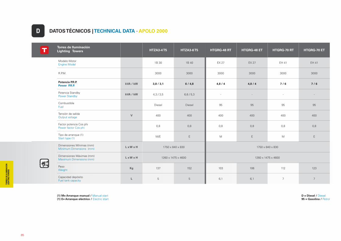
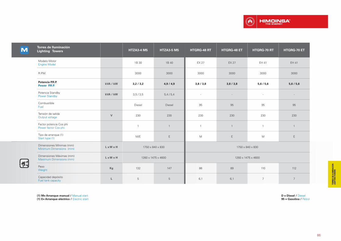
Torres de IluminaciónLighting Towers HTZA3-4 T5 HTZA3-6 T5 HTGRG-48 RT HTGRG-48 ET HTGRG-70 RT HTGRG-70 ET
Modelo Motor Engine Model 1B 30 1B 40 EX 27 EX 27 EH 41 EH 41
R.P.M. 3000 3000 3000 3000 3000 3000
Potencia P.R.P. Power P.R.P.
kVA / kW 3,8 / 3,1 6 / 4,8 4,8 / 4 4,8 / 4 7 / 6 7 / 6
Potencia StandbyPower Standby
kVA / kW 4,3 / 3,5 6,6 / 5,3 - - - -
CombustibleFuel
Diesel Diesel 95 95 95 95
Tensión de salida Output voltage
V 400 400 400 400 400 400
Factor potencia Cos phiPower factor Cos phi 0,8 0,8 0,8 0,8 0,8 0,8
Tipo de arranque (1)Start type (1) M/E E M E M E
Dimensiones Mínimas (mm)Minimum Dimensions (mm)
L x W x H 1750 x 840 x 830 1750 x 840 x 830
Dimensiones Máximas (mm)Maximum Dimensions (mm)
L x W x H 1260 x 1475 x 4600 1260 x 1475 x 4600
PesoWeight
Kg 137 152 103 106 112 123
Capacidad depósitoFuel tank capacity
L 5 5 6,1 6,1 7 7
DATOS TÉCNICOS | TECHNICAL DATA · APOLO 2000D
(1) M= Arranque manual / Manual start(1) E= Arranque eléctrico / Electric start
D = Diesel / Diesel 95 = Gasolina / Petrol
86
Torres de IluminaciónLighting Towers HTZA3-4 M5 HTZA3-5 M5 HTGRG-48 RT HTGRG-48 ET HTGRG-70 RT HTGRG-70 ET
Modelo Motor Engine Model 1B 30 1B 40 EX 27 EX 27 EH 41 EH 41
R.P.M. 3000 3000 3000 3000 3000 3000
Potencia P.R.P. Power P.R.P.
kVA / kW 3,2 / 3,2 4,9 / 4,9 3,8 / 3,8 3,8 / 3,8 5,6 / 5,6 5,6 / 5,6
Potencia StandbyPower Standby
kVA / kW 3,5 / 3,5 5,4 / 5,4 - - - -
CombustibleFuel
Diesel Diesel 95 95 95 95
Tensión de salida Output voltage
V 230 230 230 230 230 230
Factor potencia Cos phiPower factor Cos phi 1 1 1 1 1 1
Tipo de arranque (1)Start type (1) M/E E M E M E
Dimensiones Mínimas (mm)Minimum Dimensions (mm)
L x W x H 1750 x 840 x 830 1750 x 840 x 830
Dimensiones Máximas (mm)Maximum Dimensions (mm)
L x W x H 1260 x 1475 x 4600 1260 x 1475 x 4600
PesoWeight
Kg 132 147 86 89 110 112
Capacidad depósitoFuel tank capacity
L 5 5 6,1 6,1 7 7
(1) M= Arranque manual / Manual start(1) E= Arranque eléctrico / Electric start
D = Diesel / Diesel 95 = Gasolina / Petrol
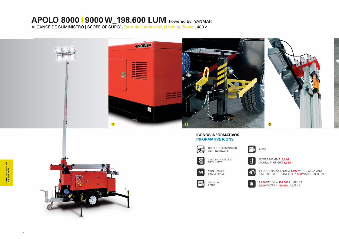
APOLO 8000 �� 9000 W_198.600 LUM Powered by: YANMARALCANCE DE SUMINISTRO | SCOPE OF SUPLY · Torre de Iluminación | Lighting Tower | 400 V
87
1 2 3
ICONOS INFORMATIVOSINFORMATIVE ICONS
GASOLINAPETROL
DIESEL
CINCUENTA HERZIOSFIFTY HERTZ
TORRES DE ILUMINACIONLIGHTING TOWERS
MONOFASICOSINGLE PHASE
6 FOCOS HALÓGENOS X 1.500 VATIOS CADA UNO. 6 METAL HALIDE LAMPS OF 1.500 WATTS EACH ONE.
ALTURA MÁXIMA: 8,9 M. MAXIMUM HEIGHT: 8,9 M.
9.000 VATIOS = 198.000 LÚMENES. 9.000 WATTS = 198.000 LUMENS.
88
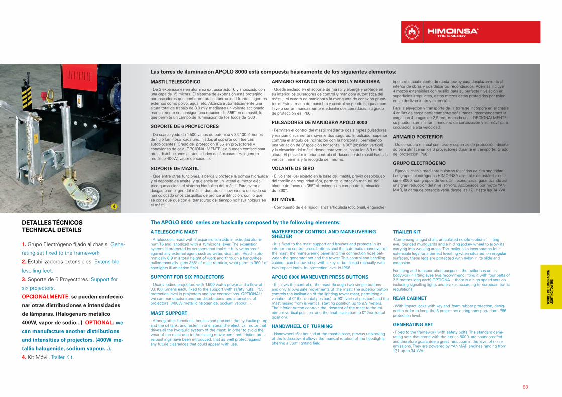
Las torres de iluminación APOLO 8000 está compuesta básicamente de los siguientes elementos:
MASTIL TELESCÓPICO
· De 3 expansiones en aluminio extrusionado T6 y anodizado con una capa de 15 micras. El sistema de expansión está protegido por rascadores que confieren total estanqueidad frente a agentes externos como polvo, agua, etc. Alcanza automáticamente una altura total de trabajo de 8,9 m y mediante un volante accionado manualmente se consigue una rotación de 355º en el mástil, lo que permite un campo de iluminación de los focos de 360º.
SOPORTE DE 6 PROYECTORES
· De cuarzo yodo de 1.500 vatios de potencia y 33.100 lúmenes de flujo luminoso cada uno, fijados al soporte con tuercas autoblocantes. Grado de protección IP55 en proyectores y conexiones de caja. OPCIONALMENTE: se pueden confeccionar otras distribuciones e intensidades de lámparas. (Halogenuro metálico 400W, vapor de sodio...).
SOPORTE DE MASTIL
· Que entre otras funciones, alberga y protege la bomba hidráulica y el depósito de aceite, y que ancla en un lateral el motor eléc-trico que acciona el sistema hidráulico del mástil. Para evitar el desgaste en el giro del mástil, durante el movimiento de izado se han colocado unos casquillos de bronce antifricción, con lo que se consigue que con el transcurso del tiempo no haya holgura en el mástil.
ARMARIO ESTANCO DE CONTROL Y MANIOBRA
· Queda anclado en el soporte de mástil y alberga y protege en su interior los pulsadores de control y maniobra automática del mástil, el cuadro de maniobra y la manguera de conexión grupo-torre. Este armario de maniobra y control se puede bloquear con llave o cerrar manualmente mediante dos cerraduras, su grado de protección es IP66.
PULSADORES DE MANIOBRA APOLO 8000
· Permiten el control del mástil mediante dos simples pulsadores y realizan únicamente movimientos seguros. El pulsador superior controla el ángulo de inclinación con la horizontal, permitiendo una variación de 0º (posición horizontal) a 90º (posición vertical) y la elevación del mástil desde esta vertical hasta los 8,9 m de altura. El pulsador inferior controla el descenso del mástil hasta la vertical mínima y la recogida del mismo.
VOLANTE DE GIRO
· El volante (6a) alojado en la base del mástil, previo desbloqueo del tornillo de seguridad (6b), permite la rotación manual del bloque de focos en 355º ofreciendo un campo de iluminación de 360°.
KIT MÓVIL
· Compuesto de eje rígido, lanza articulada (opcional), enganche
tipo anilla, abatimiento de rueda jockey para desplazamiento al interior de obras y guardabarros redondeados. Además incluye 4 mozos extensibles con husillo para su perfecta nivelación en superficies irregulares, estos mozos están protegidos por nylon en su deslizamiento y extensión.
Para la elevación y transporte de la torre se incorpora en el chasis 4 anillas de carga perfectamente señalizadas (recomendamos la carga con 4 bragas de 2,5 metros cada una). OPCIONALMENTE: se pueden suministrar luminosos de señalización y kit móvil para circulación a alta velocidad.
ARMARIO POSTERIOR
· De cerradura manual con llave y espumas de protección, diseña-do para almacenar los 6 proyectores durante el transporte. Grado de protección IP66.
GRUPO ELECTRÓGENO
· Fijado al chasis mediante bulones roscados de alta seguridad. Los grupos electrógenos HIMOINSA a instalar de estándar en la serie 8000, son grupos de versión insonorizada, garantizando así una gran reducción del nivel sonoro. Accionados por motor YAN-MAR, la gama de potencia varía desde las 17,1 hasta las 34 kVA.
The APOLO 8000 series are basically composed by the following elements:
A TELESCOPIC MAST
· A telescopic mast with 3 expansions made in extruded alumi-num T6 and anodized with a 15microns layer. The expansion system is protected by scrapers that make it fully waterproof against any external agent such as water, dust, etc. Reach auto-matically 8.9 m’s total height of work and through a handwheel pulled manually gets 355º of mast rotation, what permits 360 º of spotlights illumination field.
SUPPORT FOR SIX PROJECTORS
· Quartz iodine projectors with 1.500 watts power and a flow of 33.100 lumens each, fixed to the support with safety nuts. IP55 protection level in projectors and box connections. OPTIONAL: we can manufacture another distributions and intensities of projectors. (400W metallic halogenide, sodium vapour...).
MAST SUPPORT
· Among other functions, houses and protects the hydraulic pump and the oil tank, and fasten in one lateral the electrical motor that drives all the hydraulic system of the mast. In order to avoid the wear of the mast due to the raising movement, anti friction bron-ze bushings have been introduced, that as well protect against any future clearances that could appear with use.
WATERPROOF CONTROL AND MANEUVERING SHELTER
· It is fixed to the mast support and houses and protects in its interior the control press buttons and the automatic maneuver of the mast, the maneuvering panel and the connection hose bet-ween the generator set and the tower. This control and handling cabinet, can be locked up with a key or be closed manually with two impact locks. Its protection level is IP66.
APOLO 8000 MANEUVER PRESS BUTTONS
· It allows the control of the mast through two simple buttons and only allows safe movements of the mast. The superior button controls the inclination of the lighting tower mast, permitting a variation of 0º (horizontal position) to 90º (vertical position) and the mast raising from is vertical starting position up to 8.9 meters. The inferior button controls the descent of the mast to the mi-nimum vertical position and the final inclination to 0º (horizontal position).
HANDWHEEL OF TURNING
· Handwheel (6a) housed at the mast’s base, previus unblocking of the lockscrew, it allows the manual rotation of the floodlights, offering a 360° lighting field.
TRAILER KIT
·Comprising a rigid shaft, articulated nozzle (optional), lifting eye, rounded mudguards and a hiding jockey wheel to allow its carrying into working areas. The trailer also incorporates four extensible legs for a perfect levelling when situated on irregular surfaces, these legs are protected with nylon in its slide and extension.
For lifting and transportation purposes the trailer has on its bodywork 4 lifting eyes (we recommend lifting it with four belts of 2.5 metres long each).OPTIONAL: there is a high speed version including signalling lights and brakes according to European traffic regulations.
REAR CABINET
· With impact locks with key and foam rubber protection, desig-ned in order to keep the 6 projectors during transportation. IP66 protection level.
GENERATING SET
· Fixed to the framework with safety bolts. The standard gene-rating sets that come with the series 8000, are soundproofed and therefore guarantee a great reduction in the level of noise emissions. They are powered by YANMAR engines ranging from 17,1 up to 34 kVA.
1. Grupo Electrógeno fijado al chasis. Gene-
rating set fixed to the framework.
2. Estabilizadores extensibles. Extensible
levelling feet.
3. Soporte de 6 Proyectores. Support for
six projectors.
OPCIONALMENTE: se pueden confeccio-
nar otras distribuciones e intensidades
de lámparas. (Halogenuro metálico
400W, vapor de sodio...). OPTIONAL: we
can manufacture another distributions
and intensities of projectors. (400W me-
tallic halogenide, sodium vapour...).
4. Kit Móvil. Trailer Kit.
DETALLES TÉCNICOS TECHNICAL DETAILS
4
89
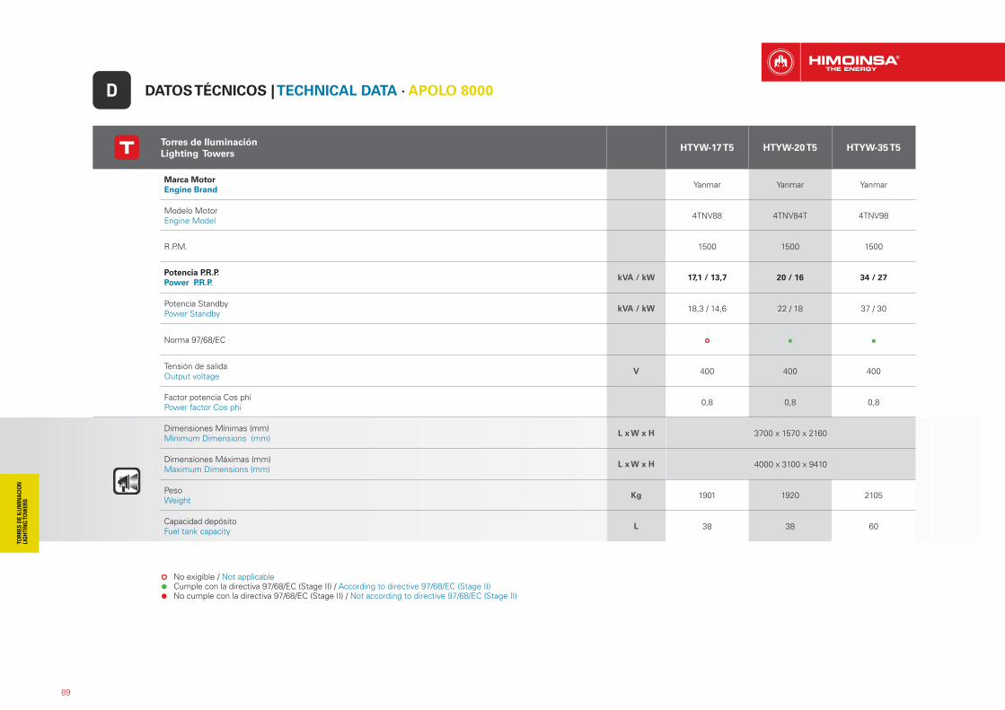
Torres de IluminaciónLighting Towers
HTYW-17 T5 HTYW-20 T5 HTYW-35 T5
Marca MotorEngine Brand Yanmar Yanmar Yanmar
Modelo Motor Engine Model 4TNV88 4TNV84T 4TNV98
R.P.M. 1500 1500 1500
Potencia P.R.P. Power P.R.P.
kVA / kW 17,1 / 13,7 20 / 16 34 / 27
Potencia StandbyPower Standby
kVA / kW 18,3 / 14,6 22 / 18 37 / 30
Norma 97/68/EC
Tensión de salida Output voltage
V 400 400 400
Factor potencia Cos phiPower factor Cos phi 0,8 0,8 0,8
Dimensiones Mínimas (mm)Minimum Dimensions (mm)
L x W x H 3700 x 1570 x 2160
Dimensiones Máximas (mm)Maximum Dimensions (mm)
L x W x H 4000 x 3100 x 9410
PesoWeight
Kg 1901 1920 2105
Capacidad depósitoFuel tank capacity
L 38 38 60
DATOS TÉCNICOS | TECHNICAL DATA · APOLO 8000D
No exigible / Not applicable Cumple con la directiva 97/68/EC (Stage II) / According to directive 97/68/EC (Stage II) No cumple con la directiva 97/68/EC (Stage II) / Not according to directive 97/68/EC (Stage II)

CUADROS DE CONTROL Y POTENCIACONTROL AND POWER PANELS:
GAMA PROFESIONAL_PROFESSIONAL RANGE
90
91
Modelo cuadro
Control panel model
Modelo Centralita
Controller modelFuncionalidad functionality SERIES
MANUAL HYW HFW HSW HVW HDW HLA HZA
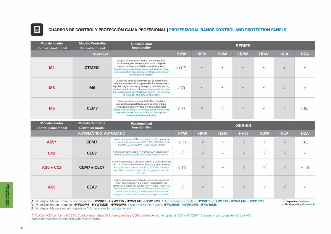
M1 CTME01
Cuadro de arranque manual por llave y pro-tección magnetotérmica tetrapolar o bipolar (según tensión y voltaje) y relé diferencial_
Key start manual control panel and thermal mag-netic protection (according to voltage and phase)
and differential relay.
� (1-2) • • • • � �
M6 M6
Cuadro de arranque manual por contacto libre tensión y protección magnetotérmica tetrapolar o bipolar (según tensión y voltaje) y relé diferencial_ Control panel of free voltage contactand tetra polar thermal magnetic protection or bipolar (depending
on voltage) and diffe-rential relay.
� (2) • • • • � �
M5 CEM7
Cuadro control manual Auto-Start digital y protección magnetotérmica tetrapolar o bipo-lar (según tensión y voltaje) y relé diferencial_
Digital manual auto-start control panel and thermal magnetic protection (according to voltage and
phase) and differential relay.
��(1) �� �� � � � ��(3)
Modelo cuadro
Control panel model
Modelo Centralita
Controller modelFuncionalidad functionality SERIES
AUTOMÁTICO_AUTOMATIC HYW HFW HSW HVW HDW HLA HZA
AS5* CEM7Cuadro automático SIN conmutación y SIN control de
red_ Automatic control panel WITHOUT ATS (Automatic Transfer Switch) and WITHOUT mains control.
��(1) �� �� � � � ��(3)
CC2 CEC7 Armario de Conmutación Himoinsa CON visualización_Himoinsa External ATS WiITH visualization display. � � � � � � �
AS5 + CC2 CEM7 + CEC7
Cuadro automático CON conmutación y CON control de red. La visualización estará en el grupo y en el armario. Automatic with mains control and ATS with visualiza-tion. The visualization will be in the genset and in the
ATS box.
���(1) �� �� �� �� �� ���(3)
AC5 CEA7
Cuadro automático por fallo de red. Armario en pared CON conmutación y protección magnetotérmica
tetrapolar o bipolar (según tensión y voltaje_Automatic Mains Failure control panel. Wall mounted Automatic control panel including transfer switch with thermal
magnetic protection (according to voltage and phase).
� � � � � � �
CUADROS DE CONTROL Y PROTECCIÓN GAMA PROFESIONAL | PROFESSIONAL RANGE CONTROL AND PROTECTION PANELS
(1) No disponible en modelos insonorizados: HYW8T5 - HYW13T5 - HYW9 M5 - HYW13M5. / Not available in models: HYW8T5 - HYW13T5 - HYW9 M5 - HYW13M5.(2) No disponible en modelos: HYW20M5 - HYW30M5 - HYW40M5. / Not available in models: HYW20M5 - HYW30M5 - HYW40M5.(3) No disponible para versión capotada / Not available for canopy version.
(*) Opción AS5 con central CEA7. Cuadro automático SIN conmutación y CON control de red. As optional AS5 with CEA7 Automatic control panel without ATS(automatic transfer switch) and with mains control.
� Disponible_Available• No disponible_Unavailable
92
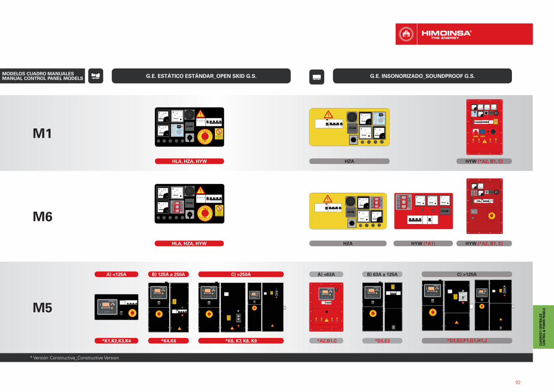
G.E. ESTÁTICO ESTÁNDAR_OPEN SKID G.S. G.E. INSONORIZADO_SOUNDPROOF G.S.
M1
M6
HZAHLA, HZA, HYW
HLA, HZA, HYW HZA HYW (*A1) HYW (*A2, B1, C)
HYW (*A2, B1, C)
M5
A) <125A
*K1,K2,K3,K4
B) 125A a 250A
*K4,K6
C) >250A
*K6, K7, K8, K9 *A2,B1,C
A) <63A
*D3,E2
B) 63A a 125A
*D3,E2,F1,G1,H1,J
C) >125A
MODELOS CUADRO MANUALES MANUAL CONTROL PANEL MODELS
* Versión Constructiva_Constructive Version
93
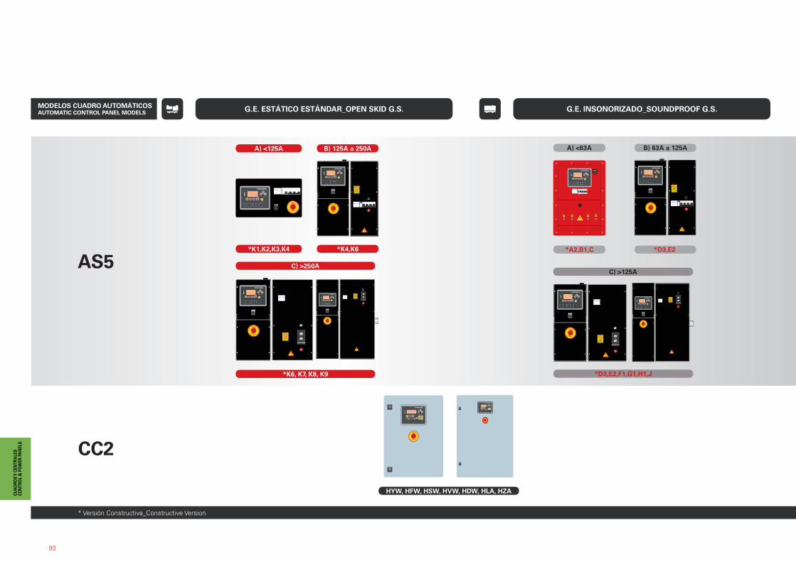
G.E. ESTÁTICO ESTÁNDAR_OPEN SKID G.S. G.E. INSONORIZADO_SOUNDPROOF G.S.
AS5
CC2
A) <125A
*K1,K2,K3,K4
B) 125A a 250A
*K4,K6
C) >250A
*K6, K7, K8, K9
*A2,B1,C
A) <63A
*D3,E2
B) 63A a 125A
*D3,E2,F1,G1,H1,J
C) >125A
HYW, HFW, HSW, HVW, HDW, HLA, HZA
* Versión Constructiva_Constructive Version
MODELOS CUADRO AUTOMÁTICOS AUTOMATIC CONTROL PANEL MODELS
94
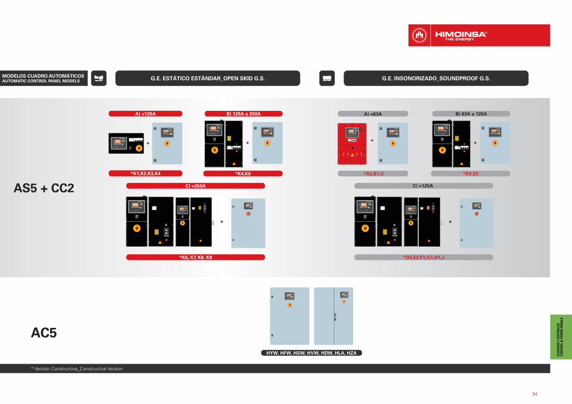
G.E. ESTÁTICO ESTÁNDAR_OPEN SKID G.S. G.E. INSONORIZADO_SOUNDPROOF G.S.
* Versión Constructiva_Constructive Version
AS5 + CC2
+
*K6, K7, K8, K9
C) >250A
AC5HYW, HFW, HSW, HVW, HDW, HLA, HZA
+ +
*K1,K2,K3,K4
B) 125A a 250A
*K4,K6
+
A) <125A
+ +
A) <63A
*A2,B1,C *D3,E2
B) 63A a 125A
C) >125A
*D3,E2,F1,G1,H1,J
MODELOS CUADRO AUTOMÁTICOS AUTOMATIC CONTROL PANEL MODELS
95
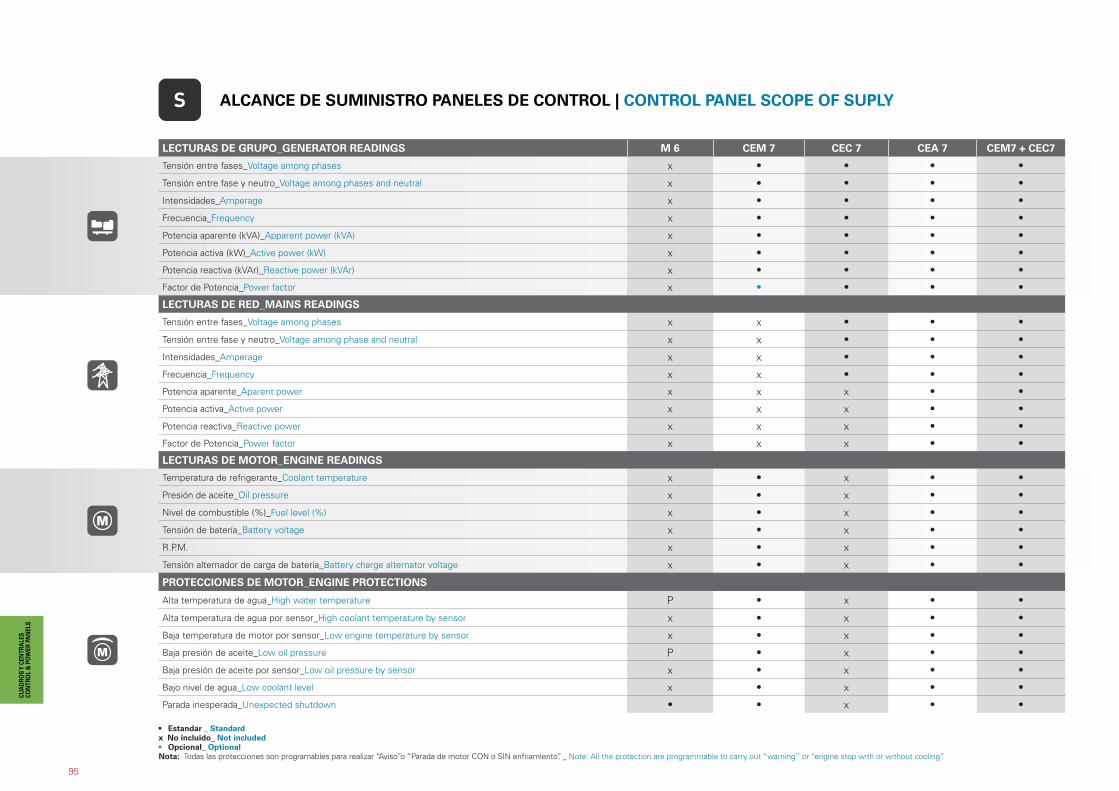
LECTURAS DE GRUPO_GENERATOR READINGS M 6 CEM 7 CEC 7 CEA 7 CEM7 + CEC7
Tensión entre fases_Voltage among phases x • • • •
Tensión entre fase y neutro_Voltage among phases and neutral x • • • •
Intensidades_Amperage x • • • •
Frecuencia_Frequency x • • • •
Potencia aparente (kVA)_Apparent power (kVA) x • • • •
Potencia activa (kW)_Active power (kW) x • • • •
Potencia reactiva (kVAr)_Reactive power (kVAr) x • • • •
Factor de Potencia_Power factor x • • • •
LECTURAS DE RED_MAINS READINGS
Tensión entre fases_Voltage among phases x x • • •
Tensión entre fase y neutro_Voltage among phase and neutral x x • • •
Intensidades_Amperage x x • • •
Frecuencia_Frequency x x • • •
Potencia aparente_Aparent power x x x • •
Potencia activa_Active power x x x • •
Potencia reactiva_Reactive power x x x • •
Factor de Potencia_Power factor x x x • •
LECTURAS DE MOTOR_ENGINE READINGS
Temperatura de refrigerante_Coolant temperature x • x • •
Presión de aceite_Oil pressure x • x • •
Nivel de combustible (%)_Fuel level (%) x • x • •
Tensión de batería_Battery voltage x • x • •
R.P.M. x • x • •
Tensión alternador de carga de batería_Battery charge alternator voltage x • x • •
PROTECCIONES DE MOTOR_ENGINE PROTECTIONS
Alta temperatura de agua_High water temperature P • x • •
Alta temperatura de agua por sensor_High coolant temperature by sensor x • x • •
Baja temperatura de motor por sensor_Low engine temperature by sensor x • x • •
Baja presión de aceite_Low oil pressure P • x • •
Baja presión de aceite por sensor_Low oil pressure by sensor x • x • •
Bajo nivel de agua_Low coolant level x • x • •
Parada inesperada_Unexpected shutdown • • x • •
S ALCANCE DE SUMINISTRO PANELES DE CONTROL | CONTROL PANEL SCOPE OF SUPLY
• Estandar _ Standardx No incluido_ Not included• Opcional_ OptionalNota: Todas las protecciones son programables para realizar “Aviso”o “Parada de motor CON o SIN enfriamiento”. _ Note: All the protection are programmable to carry out “warning” or “engine stop with or without cooling”.
96
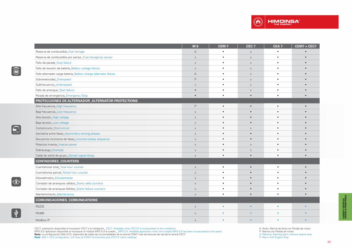
M 6 CEM 7 CEC 7 CEA 7 CEM7 + CEC7
Reserva de combustible_Fuel storage A • x • •
Reserva de combustible por sensor_Fuel storage by sensor x • x • •
Fallo de parada_Stop failure x • x • •
Fallo de tensión de batería_Battery voltage failure x • x • •
Fallo alternador carga batería_Battery charge alternator failure A • x • •
Sobrevelocidad_Overspeed P • x • •
Subfrecuencia_Underspeed x • x • •
Fallo de arranque_Start failure • • x • •
Parada de emergencia_Emergency Stop • • • • •
PROTECCIONES DE ALTERNADOR_ALTERNATOR PROTECTIONS
Alta frecuencia_High frequency P • • • •
Baja frecuencia_Low frequency x • • • •
Alta tensión_High voltage x • • • •
Baja tensión_Low voltage x • • • •
Cortocircuito_Short-circuit x • x • •
Asimetría entre fases_Asymmetry among phases x • • • •
Secuencia incorrecta de fases_Incorrect phase sequence x • • • •
Potencia Inversa_Inverse power x • x • •
Sobrecarga_Overload x • x • •
Caída de señal de grupo_Genset signal droop x • • • •
CONTADORES_COUNTERS
Cuentahoras total_Total hour counter x • • • •
Cuentahoras parcial_Partial hour counter x • • • •
Kilowatímetro_Kilowatimeter x • • • •
Contador de arranques válidos_Starts valid counters x • • • •
Contador de arranques fallidos_Starts failure counters x • • • •
Mantenimiento_Maintenance x • • • •
COMUNICACIONES_COMUNICATIONS
RS232 x • • • •
RS485 x • • • •
Modbus IP x • • • •
A: Aviso. Alarma de Aviso sin Parada de motor.P: Alarma con Parada de motor.A: Warning. Warning alarm without engine stop.P: Alarm with Engine Stop
CEC7: prestación disponible al incorporar CEC7 a la instalación_ CEC7: Available when CEC7.2 is incorporated to the installation.MPS 5.0: aplicación disponible al incorporar el módulo MPS 5.0 al cuadro._ MPS 5.0: Available application when the module MPS 5.0 has been incorporated to the panel.Nota: La configuración AS5+CC2, dispondrá de todas las funcionalidades de la central CEM7 mas las lecturas de red de la central CEC7.Note: AS5 + CC2 configuration, will have all CEM7 functionality plus CEC7.2 mains readings
97
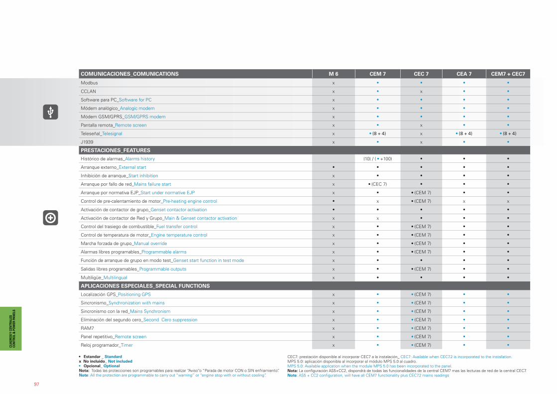
COMUNICACIONES_COMUNICATIONS M 6 CEM 7 CEC 7 CEA 7 CEM7 + CEC7
Modbus x • • • •
CCLAN x • x • •
Software para PC_Software for PC x • • • •
Módem analógico_Analogic modem x • • • •
Módem GSM/GPRS_GSM/GPRS modem x • • • •
Pantalla remota_Remote screen x • x • •
Teleseñal_Telesignal x • (8 + 4) x • (8 + 4) • (8 + 4)
J1939 x • x • •
PRESTACIONES_FEATURES
Histórico de alarmas_Alarms history (10) / ( • +100) • • •
Arranque externo_External start • • • • •
Inhibición de arranque_Start inhibition x • • • •
Arranque por fallo de red_Mains failure start x • (CEC 7) • • •
Arranque por normativa EJP_Start under normative EJP x • • (CEM 7) • •
Control de pre-calentamiento de motor_Pre-heating engine control • x • (CEM 7) x x
Activación de contactor de grupo_Genset contactor activation • • • • •
Activación de contactor de Red y Grupo_Main & Genset contactor activation x x • • •
Control del trasiego de combustible_Fuel transfer control x • • (CEM 7) • •
Control de temperatura de motor_Engine temperature control x • • (CEM 7) • •
Marcha forzada de grupo_Manual override x • • (CEM 7) • •
Alarmas libres programables_Programmable alarms x • • (CEM 7) • •
Función de arranque de grupo en modo test_Genset start function in test mode x • • • •
Salidas libres programables_Programmable outputs x • • (CEM 7) • •
Multiligüe_Multilingual x • • • •
APLICACIONES ESPECIALES_SPECIAL FUNCTIONS
Localización GPS_Positioning GPS x • • (CEM 7) • •
Sincronismo_Synchronization with mains x • • (CEM 7) • •
Sincronismo con la red_Mains Synchronism x • • (CEM 7) • •
Eliminación del segundo cero_Second Cero suppression x • • (CEM 7) • •
RAM7 x • • (CEM 7) • •
Panel repetitivo_Remote screen x • • (CEM 7) • •
Reloj programador_Timer x • • (CEM 7) • •
• Estandar _ Standardx No incluido_ Not included• Opcional_ OptionalNota: Todas las protecciones son programables para realizar “Aviso”o “Parada de motor CON o SIN enfriamiento”.Note: All the protection are programmable to carry out “warning” or “engine stop with or without cooling”.
CEC7: prestación disponible al incorporar CEC7 a la instalación_ CEC7: Available when CEC7.2 is incorporated to the installation.MPS 5.0: aplicación disponible al incorporar el módulo MPS 5.0 al cuadro.MPS 5.0: Available application when the module MPS 5.0 has been incorporated to the panel.Nota: La configuración AS5+CC2, dispondrá de todas las funcionalidades de la central CEM7 mas las lecturas de red de la central CEC7.Note: AS5 + CC2 configuration, will have all CEM7 functionality plus CEC7.2 mains readings
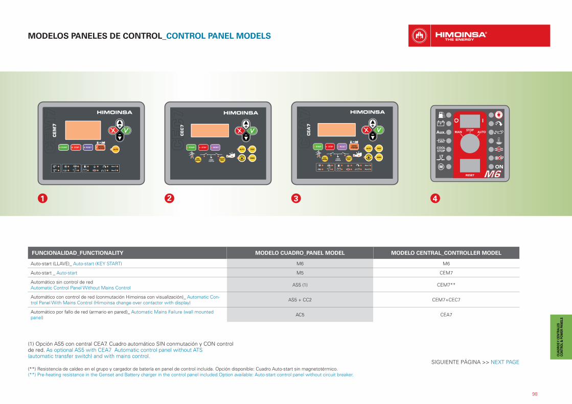
MODELOS PANELES DE CONTROL_CONTROL PANEL MODELS
98
(**) Resistencia de caldeo en el grupo y cargador de batería en panel de control incluida. Opción disponible: Cuadro Auto-start sin magnetotérmico.(**) Pre-heating resistance in the Genset and Battery charger in the control panel included.Option available: Auto-start control panel without circuit breaker.
FUNCIONALIDAD_FUNCTIONALITY MODELO CUADRO_PANEL MODEL MODELO CENTRAL_CONTROLLER MODEL
Auto-start (LLAVE)_ Auto-start (KEY START) M6 M6
Auto-start _ Auto-start M5 CEM7
Automático sin control de redAutomatic Control Panel Without Mains Control AS5 (1) CEM7**
Automático con control de red (conmutación Himoinsa con visualización)_ Automatic Con-trol Panel With Mains Control (Himoinsa change over contactor with display) AS5 + CC2 CEM7+CEC7
Automático por fallo de red (armario en pared)_ Automatic Mains Failure (wall mounted panel) AC5 CEA7
1 2 3 4
SIGUIENTE PÁGINA >> NEXT PAGE
(1) Opción AS5 con central CEA7. Cuadro automático SIN conmutación y CON control de red. As optional AS5 with CEA7 Automatic control panel without ATS(automatic transfer switch) and with mains control.
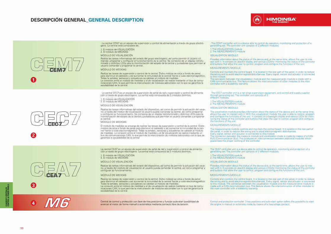
99
DESCRIPCIÓN GENERAL_GENERAL DESCRIPTION
3
4
· La central CEM7 es un equipo de supervisión y control de alimentación a través de grupo electró-geno. La central está compuesta de:
1. El módulo de VISUALIZACIÓN2. El módulo de MEDIDASMÓDULO DE VISUALIZACIÓNRealiza las tareas informativas del estado del grupo electrógeno, así como permitir al usuario co-mandar, programar y configurar el funcionamiento de la central. Se compone de un display retroilu-minado y distintos LEDs para la monitorización del estado de la central y pulsadores que permiten al usuario comandar y programar la central.
MÓDULO DE MEDIDAS
Realiza las tareas de supervisión y control de la central. Dicho módulo se sitúa a fondo de panel para disminuir el cableado y así aumentar la inmunidad de la central frente a ruido electromagnético.Todas la señales, sensores y actuadores se cablean al módulo de medidas.La conexión entre el módulo de medidas y el de visualización se realiza mediante un bus de comu-nicaciones CAN, lo que permite la interconexión de módulos adicionales con lo que se garantiza la escalabilidad de la central.
· The CEM7 controller unit is a device able to control de operation, monitoring and protection of a generating set. The controller unit consists of 2 different modules:1. The VISUALIZATION module2. The MEASUREMENTS module
VISUALIZATION MODULE
Provides information about the status of the device and, at the same time, allows the user to inte-ract with it. It consists on abacklit display and various LEDsfor monitoring the status of the controller and buttons that allow the user to control, program and configure the functions of the unit.
MEASUREMENTS MODULE
Controls and monitors the control board. It is located in the rear part of the panel, in order to reduce the wiring and to avoid electromagneticdisturbances. Every signal, sensor and actuator is connected to this module.The connexion between the visualization module and the measurements module is made with a CAN communication bus. This feature allows the intercommunion of other modules to the main controller with a scalability warranty.
1
2
· La central CEC7 es un equipo de supervisión de señal de red y supervisión y control de alimenta-ción a través de grupo electrógeno. La central está compuesta de 2 módulos distintos:
1. El módulo de VISUALIZACIÓN2. El módulo de MEDIDAS
MÓDULO DE VISUALIZACIÓN
Realiza las tareas informativas del estado del dispositivo, así como de permitir la actuación del usua-rio; a través del móduo de visualización el usuario puede comandar la central, así como programar y configurar su funcionamiento. Se compone de un display retroiluminado y distintos LEDs para la monitorización del estado de la central y pulsadores que permiten al usuario comandar y programar la central.MÓDULO DE MEDIDAS
El módulo de medidas se encarga de realizar las tareas de supervisión y control de la central. Dicho módulo se sitúa a fondo de panel para disminuir el cableado y así aumentar la inmunidad de la cen-tral frente a ruido electromagnético. Todas la señales, sensores y actuadores se cablean al módulode medidas. La conexión entre el módulo de medidas y el de visualización se realiza mediante un bus de comunicaciones CAN, lo que permite la interconexión de módulos adicionales con lo que se garantiza la escalabilidad de la central
· The CEC7 controller unit is a net sings supervision equipment, and control and supply supplier through generating set. The controller unit consists of 2different modules:
1. The VISUALIZATION module2. The MEASUREMENTS module
VISUALIZATION MODULE
The visualization module provides information about the status of the device and, at the same time, allows the user to interact with it. With this visualization module the user is able to control, program and configure the functions of the unit. It consists on a backlight display and various LEDs for moni-toring the status of the controller and buttons that allow the user to control, program and configure the functions of the unit.
MEASUREMENTS MODULE
The measurements module controls and monitors the control board. It is located in the rear part of the panel, in order to reduce the wiring and to avoid electromagnetic disturbances.Every signal, sensor and actuator is connected to this moduleThe connection between the measure module and visualization mode is made by means of a CAN BUS (Communication Bus). This produces an interconnection between additional modules which guarantees the proper working of the controller.
La central CEA7 es un equipo de supervisión de señal de red y supervisión y control de alimenta-ción a través de grupo electrógeno. La central está compuesta de 2 módulos distintos:
1. El módulo de VISUALIZACIÓN2. El módulo de MEDIDAS
MÓDULO DE VISUALIZACIÓN
Realiza las tareas informativas del estado del dispositivo, así como de permitir la actuación del usua-rio; a través del módulo de visualización el usuario puede comandar la central, así como programar y configurar su funcionamiento.
MÓDULO DE MEDIDAS
Realiza las tareas de supervisión y control de la central. Dicho módulo se sitúa a fondo de panel para disminuir el cableado y así aumentar la inmunidad de la central frente a ruido electromagnético. Todas la señales, sensores y actuadores se cablean al módulo de medidas.La conexión entre el módulo de medidas y el de visualización se realiza mediante un bus de comu-nicaciones CAN, lo que permite la interconexión de módulos adicionales con lo que se garantiza la escalabilidad de la central.
The CEA7 controller unit is a device able to control de operation, monitoring and protection of a generating set. The controller unit consists of 2 different modules:
1. The VISUALIZATION module2. The MEASUREMENTS module
VISUALIZATION MODULE
Provides information about the status of the device and, at the same time, allows the user to inte-ract with it. It consists on abacklit display and various LEDsfor monitoring the status of the controller and buttons that allow the user to control, program and configure the functions of the unit.
MEASUREMENTS MODULE
Controls and monitors the control board. It is located in the rear part of the panel, in order to reduce the wiring and to avoid electromagneticdisturbances. Every signal, sensor and actuator is connected to this module. The connexion between the visualization module and the measurements module is made with a CAN communication bus. This feature allows the intercommunion of other modules to the main controller with a scalability warranty.
Central de control y protección con llave de tres posiciones y función auto-start (posibilidad de arrancar el motor de forma manual o automática mediante contacto libre de tensión.
Control and protection controller. 3 key positions and auto-start option (offers the possibility to start the engine in manual or automatic mode by means of a free-voltaje contact)

100
OP
OPCIONALES_OPTIONALS: GAMA PROFESIONAL_PROFESSIONAL RANGE
GAMA HR_HR RANGE
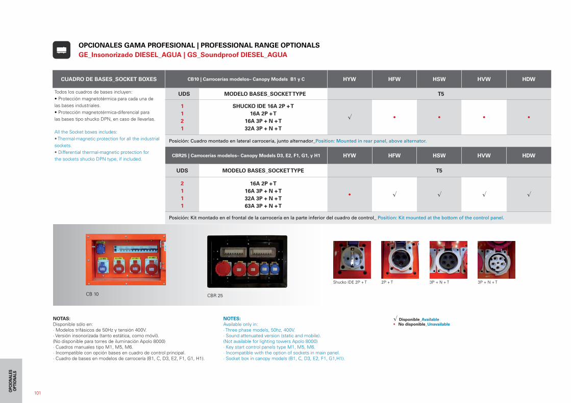
101
CUADRO DE BASES_SOCKET BOXES CB10 | Carrocerías modelos– Canopy Models B1 y C HYW HFW HSW HVW HDW
Todos los cuadros de bases incluyen:• Protección magnetotérmica para cada una de las bases industriales.• Protección magnetotérmica-diferencial para las bases tipo shucko DPN, en caso de llevarlas.
All the Socket boxes includes:• Thermal-magnetic protection for all the industrial sockets.• Differential thermal-magnetic protection for the sockets shucko DPN type, if included.
UDS MODELO BASES_SOCKET TYPE T5
112 1
SHUCKO IDE 16A 2P + T16A 2P + T
16A 3P + N + T32A 3P + N + T
� • • • •
Posición: Cuadro montado en lateral carrocería, junto alternador_Position: Mounted in rear panel, above alternator.
CBR25 | Carrocerías modelos– Canopy Models D3, E2, F1, G1, y H1 HYW HFW HSW HVW HDW
UDS MODELO BASES_SOCKET TYPE T5
2111
16A 2P + T16A 3P + N + T32A 3P + N + T63A 3P + N + T
• � � � �
Posición: Kit montado en el frontal de la carrocería en la parte inferior del cuadro de control_ Position: Kit mounted at the bottom of the control panel.
Shucko IDE 2P + T 2P + T 3P + N + T 3P + N + T
CB 10
OPCIONALES GAMA PROFESIONAL | PROFESSIONAL RANGE OPTIONALS GE_Insonorizado DIESEL_AGUA | GS_Soundproof DIESEL_AGUA
CBR 25
NOTAS:Disponible sólo en:· Modelos trifásicos de 50Hz y tensión 400V.· Versión insonorizada (tanto estática, como móvil). (No disponible para torres de iluminación Apolo 8000)· Cuadros manuales tipo M1, M5, M6.· Incompatible con opción bases en cuadro de control principal.· Cuadro de bases en modelos de carrocería (B1, C, D3, E2, F1, G1, H1).
NOTES:Available only in:· Three phase models, 50hz, 400V.· Sound attenuated version (static and mobile). (Not available for lighting towers Apolo 8000)· Key start control panels type M1, M5, M6.· Incompatible with the option of sockets in main panel.· Socket box in canopy models (B1, C, D3, E2, F1, G1,H1).
� Disponible_Available• No disponible_Unavailable
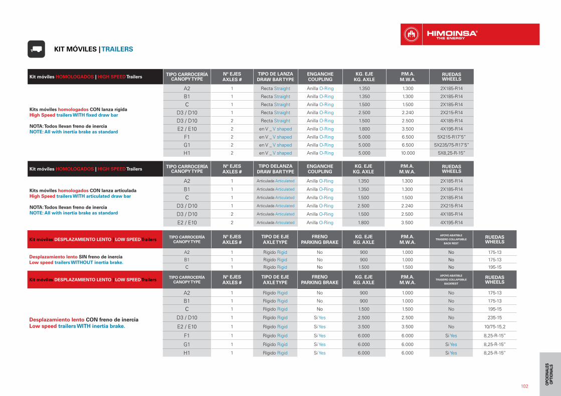
102
Kit móviles DESPLAZAMIENTO LENTO | LOW SPEED Trailers TIPO CARROCERÍACANOPY TYPE
Nº EJESAXLES #
TIPO DE EJEAXLE TYPE
FRENOPARKING BRAKE
KG. EJEKG. AXLE
P.M.A.M.W.A.
APOYO ABATIBLE
TRASERO COLLAPSIBLE
BACK REST
RUEDASWHEELS
Desplazamiento lento SIN freno de inerciaLow speed trailers WITHOUT inertia brake.
A2 1 Rígido Rigid No 900 1.000 No 175-13
B1 1 Rígido Rigid No 900 1.000 No 175-13
C 1 Rígido Rigid No 1.500 1.500 No 195-15
Kit móviles DESPLAZAMIENTO LENTO | LOW SPEED Trailers TIPO CARROCERÍACANOPY TYPE
Nº EJESAXLES #
TIPO DE EJEAXLE TYPE
FRENOPARKING BRAKE
KG. EJEKG. AXLE
P.M.A.M.W.A.
APOYO ABATIBLE
TRASERO COLLAPSIBLE
BACKREST
RUEDASWHEELS
Desplazamiento lento CON freno de inerciaLow speed trailers WITH inertia brake.
A2 1 Rígido Rigid No 900 1.000 No 175-13
B1 1 Rígido Rigid No 900 1.000 No 175-13
C 1 Rígido Rigid No 1.500 1.500 No 195-15
D3 / D10 1 Rígido Rigid Si Yes 2.500 2.500 No 235-15
E2 / E10 1 Rígido Rigid Si Yes 3.500 3.500 No 10/75-15,2
F1 1 Rígido Rigid Si Yes 6.000 6.000 Si Yes 8,25-R-15’’
G1 1 Rígido Rigid Si Yes 6.000 6.000 Si Yes 8,25-R-15’’
H1 1 Rígido Rigid Si Yes 6.000 6.000 Si Yes 8,25-R-15’’
Kit móviles HOMOLOGADOS | HIGH SPEED Trailers TIPO CARROCERÍACANOPY TYPE
Nº EJESAXLES #
TIPO DE LANZADRAW BAR TYPE
ENGANCHECOUPLING
KG. EJEKG. AXLE
P.M.A.M.W.A.
RUEDASWHEELS
Kits móviles homologados CON lanza rígidaHigh Speed trailers WITH fixed draw bar
NOTA: Todos llevan freno de inerciaNOTE: All with inertia brake as standard
A2 1 Recta Straight Anilla O-Ring 1.350 1.300 2X185-R14
B1 1 Recta Straight Anilla O-Ring 1.350 1.300 2X185-R14
C 1 Recta Straight Anilla O-Ring 1.500 1.500 2X185-R14
D3 / D10 1 Recta Straight Anilla O-Ring 2.500 2.240 2X215-R14
D3 / D10 2 Recta Straight Anilla O-Ring 1.500 2.500 4X185-R14
E2 / E10 2 en V _ V shaped Anilla O-Ring 1.800 3.500 4X195-R14
F1 2 en V _ V shaped Anilla O-Ring 5.000 6.500 5X215-R17’5’’
G1 2 en V _ V shaped Anilla O-Ring 5.000 6.500 5X235/75-R17’5’’
H1 2 en V _ V shaped Anilla O-Ring 5.000 10.000 5X8,25-R-15’’
Kit móviles HOMOLOGADOS | HIGH SPEED Trailers TIPO CARROCERÍACANOPY TYPE
Nº EJESAXLES #
TIPO DELANZADRAW BAR TYPE
ENGANCHECOUPLING
KG. EJEKG. AXLE
P.M.A.M.W.A.
RUEDASWHEELS
Kits móviles homologados CON lanza articuladaHigh Speed trailers WITH articulated draw bar
NOTA: Todos llevan freno de inerciaNOTE: All with inertia brake as standard
A2 1 Articulada Articulated Anilla O-Ring 1.350 1.300 2X185-R14
B1 1 Articulada Articulated Anilla O-Ring 1.350 1.300 2X185-R14
C 1 Articulada Articulated Anilla O-Ring 1.500 1.500 2X185-R14
D3 / D10 1 Articulada Articulated Anilla O-Ring 2.500 2.240 2X215-R14
D3 / D10 2 Articulada Articulated Anilla O-Ring 1.500 2.500 4X185-R14
E2 / E10 2 Articulada Articulated Anilla O-Ring 1.800 3.500 4X195-R14
KIT MÓVILES | TRAILERS
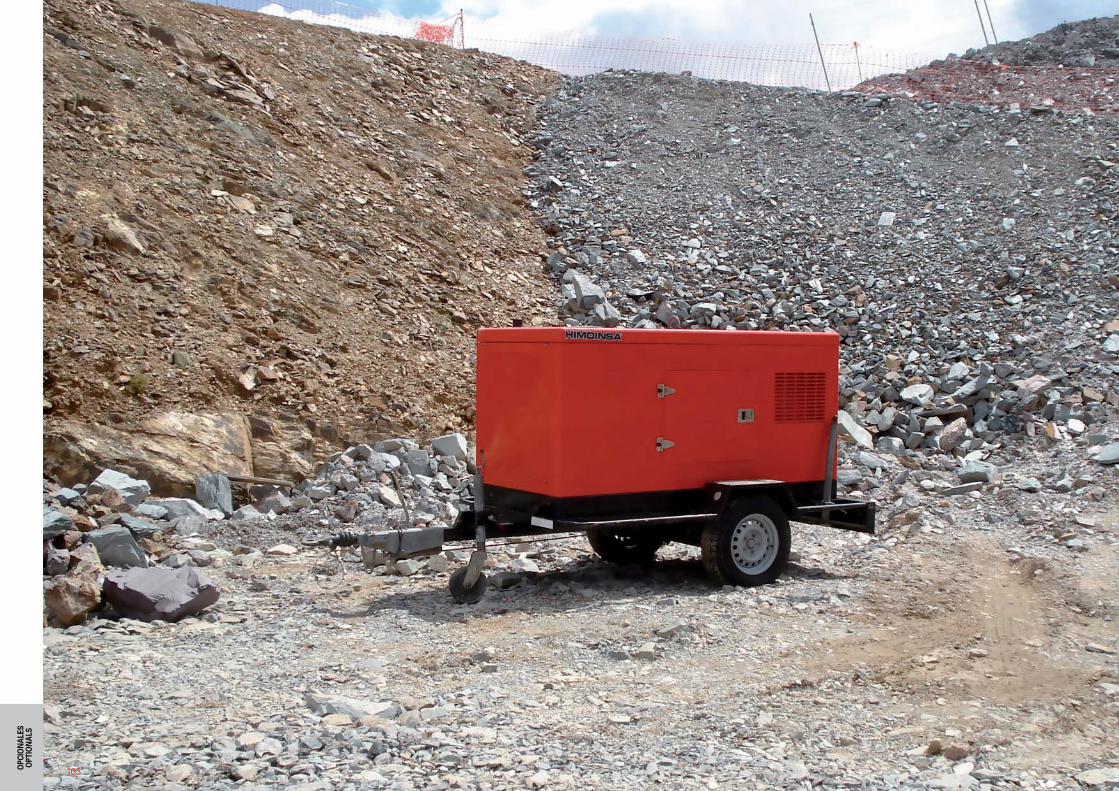
103
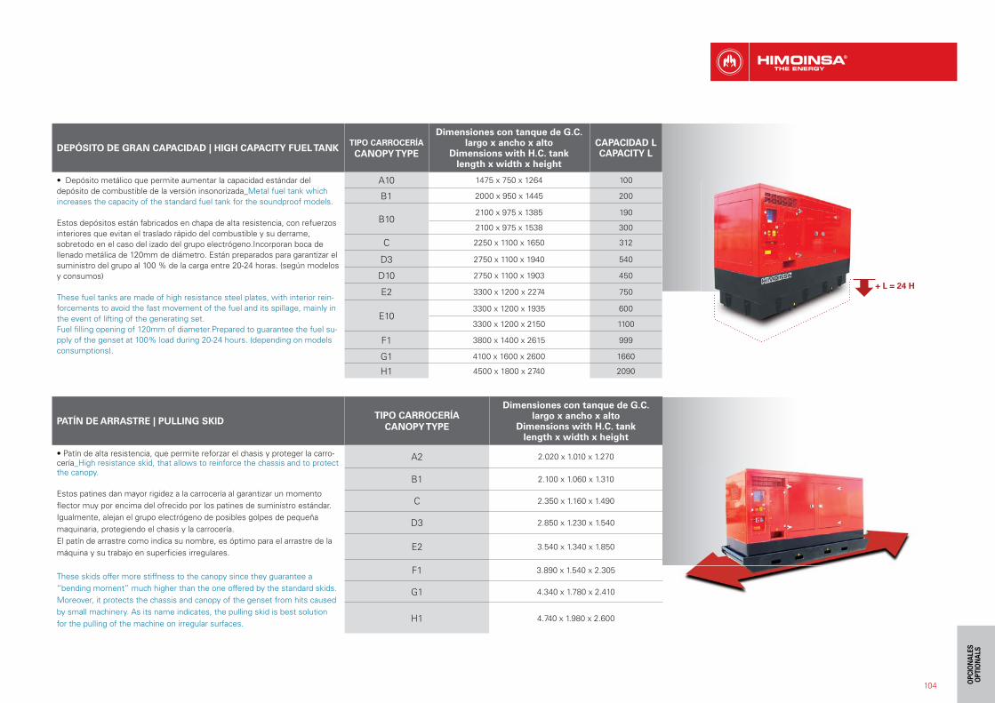
104
DEPÓSITO DE GRAN CAPACIDAD | HIGH CAPACITY FUEL TANKTIPO CARROCERÍACANOPY TYPE
Dimensiones con tanque de G.C.largo x ancho x alto
Dimensions with H.C. tanklength x width x height
CAPACIDAD L CAPACITY L
• Depósito metálico que permite aumentar la capacidad estándar del depósito de combustible de la versión insonorizada_Metal fuel tank which increases the capacity of the standard fuel tank for the soundproof models.
Estos depósitos están fabricados en chapa de alta resistencia, con refuerzos interiores que evitan el traslado rápido del combustible y su derrame, sobretodo en el caso del izado del grupo electrógeno.Incorporan boca de llenado metálica de 120mm de diámetro. Están preparados para garantizar el suministro del grupo al 100 % de la carga entre 20-24 horas. (según modelos y consumos)
These fuel tanks are made of high resistance steel plates, with interior rein-forcements to avoid the fast movement of the fuel and its spillage, mainly in the event of lifting of the generating set.Fuel filling opening of 120mm of diameter.Prepared to guarantee the fuel su-pply of the genset at 100% load during 20-24 hours. (depending on models consumptions).
A10 1475 x 750 x 1264 100
B1 2000 x 950 x 1445 200
B102100 x 975 x 1385 190
2100 x 975 x 1538 300
C 2250 x 1100 x 1650 312
D3 2750 x 1100 x 1940 540
D10 2750 x 1100 x 1903 450
E2 3300 x 1200 x 2274 750
E103300 x 1200 x 1935 600
3300 x 1200 x 2150 1100
F1 3800 x 1400 x 2615 999
G1 4100 x 1600 x 2600 1660
H1 4500 x 1800 x 2740 2090
PATÍN DE ARRASTRE | PULLING SKIDTIPO CARROCERÍA
CANOPY TYPE
Dimensiones con tanque de G.C.largo x ancho x alto
Dimensions with H.C. tanklength x width x height
• Patín de alta resistencia, que permite reforzar el chasis y proteger la carro-cería_High resistance skid, that allows to reinforce the chassis and to protect the canopy.
Estos patines dan mayor rigidez a la carrocería al garantizar un momento flector muy por encima del ofrecido por los patines de suministro estándar. Igualmente, alejan el grupo electrógeno de posibles golpes de pequeña maquinaria, protegiendo el chasis y la carrocería.El patín de arrastre como indica su nombre, es óptimo para el arrastre de la máquina y su trabajo en superficies irregulares.
These skids offer more stiffness to the canopy since they guarantee a “bending moment” much higher than the one offered by the standard skids. Moreover, it protects the chassis and canopy of the genset from hits caused by small machinery. As its name indicates, the pulling skid is best solution for the pulling of the machine on irregular surfaces.
A2 2.020 x 1.010 x 1.270
B1 2.100 x 1.060 x 1.310
C 2.350 x 1.160 x 1.490
D3 2.850 x 1.230 x 1.540
E2 3.540 x 1.340 x 1.850
F1 3.890 x 1.540 x 2.305
G1 4.340 x 1.780 x 2.410
H1 4.740 x 1.980 x 2.600
+ L = 24 H
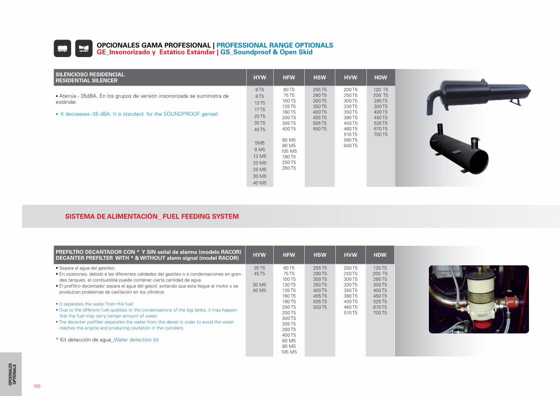
105
SILENCIOSO RESIDENCIALRESIDENTIAL SILENCER HYW HFW HSW HVW HDW
• Atenúa - 35dBA. En los grupos de versión insonorizada se suministra deestándar.
• It decreases -35 dBA. It is standard for the SOUNDPROOF genset.
6 T58 T5 13 T5 17 T5 20 T535 T5 45 T5
5M59 M513 M520 M525 M530 M540 M5
60 T5 75 T5 100 T5 135 T5160 T5 200 T5 305 T5 400 T5
60 M580 M5105 M5180 T5 250 T5350 T5
255 T5280 T5300 T5350 T5400 T5455 T5505 T5550 T5
200 T5250 T5300 T5330 T5350 T5380 T5400 T5460 T5510 T5580 T5640 T5
120 T5200 T5285 T5300 T5400 T5450 T5525 T5670 T5700 T5
OPCIONALES GAMA PROFESIONAL | PROFESSIONAL RANGE OPTIONALS GE_Insonorizado y Estático Estándar | GS_Soundproof & Open Skid
SISTEMA DE ALIMENTACIÓN_ FUEL FEEDING SYSTEM
PREFILTRO DECANTADOR CON * Y SIN señal de alarma (modelo RACOR)DECANTER PREFILTER WITH * & WITHOUT alarm signal (model RACOR) HYW HFW HSW HVW HDW
• Separa el agua del gasóleo.• En ocasiones, debido a las diferentes calidades del gasóleo o a condensaciones en gran-
des tanques, el combustible puede contener cierta cantidad de agua.• El prefiltro decantador separa el agua del gasoil, evitando que esta llegue al motor y se
produzcan problemas de cavitación en los cilindros.
• It separates the water from the fuel.• Due to the different fuel qualities or the condensations of the big tanks, it may happen
that the fuel may carry certain amount of water.• The decanter prefilter separates the water from the diesel in order to avoid the water
reaches the engine and producing cavitation in the cylinders.
* Kit detección de agua_Water detection kit
35 T545 T5
30 M540 M5
60 T5 75 T5 100 T5 130 T5135 T5 160 T5180 T5200 T5250 T5300 T5305 T5350 T5400 T560 M580 M5105 M5
255 T5280 T5300 T5350 T5400 T5455 T5505 T5550 T5
200 T5250 T5300 T5330 T5350 T5380 T5400 T5460 T5510 T5
120 T5200 T5285 T5300 T5400 T5450 T5525 T5670 T5700 T5
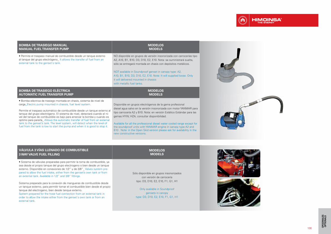
VÁLVULA 3 VÍAS LLENADO DE COMBUSTIBLE3 WAY VALVE FUEL FILLING
MODELOSMODELS
• Sistema de válvulas preparadas para permitir la toma de combustible, ya sea desde el propio tanque del grupo electrogeno o bien desde un tanque externo. Disponible en conexiones de 1/2” y de 3/8”_ Valves system pre-pared to allow the fuel intake, either from the genset’s own tank or from an external tank. Available in 1/2” and 3/8” fittings.
Sistema preparado para la conexión de mangueras de combustible desde un tanque externo, para permitir tomar el combustible bien desde el propio tanque del electrogeno, bien desde tanque externo.System prepared for the hose fuel connection from an external tank in order to allow the intake either from the genset´s own tank or from an external tank.
Sólo disponible en grupos insonorizadoscon versión de carrocería
tipo: D3, D10, E2, E10, F1, G1, H1
Only available in Soundproofgensets in canopy
type: D3, D10, E2, E10, F1, G1, H1
106
BOMBA DE TRASIEGO MANUALMANUAL FUEL TRANSFER PUMP
MODELOSMODELS
• Permite el traspaso manual de combustible desde un tanque externo al tanque del grupo electrógeno_ It allows the transfer of fuel from an external tank to the genset´s tank.
NO disponble en grupos de versión insonorizada con carrocerías tipo A2, A10, B1, B10, D3, D10, E2, E10. Nota: se suministrará suelta, sólo se entregará montada en chasis con depósitos metálicos.
NOT available in Soundproof genset in canopy type: A2,A10, B1, B10, D3, D10, E2, E10. Note: It will supplied loose. Onlyit will delivered mounted in chassiswith metallic fuel tanks.
BOMBA DE TRASIEGO ELÉCTRICAAUTOMATIC FUEL TRANSFER PUMP
MODELOSMODELS
• Bomba eléctrica de trasiego montada en chasis, sistema de nivel de carga_Electric pump mounted in chassis, fuel level system.
Permite el traspaso automático de combustible desde un tanque externo al tanque del grupo electrógeno. El sistema de nivel, detectará cuando el ni-vel del tanque de combustible es bajo para arrancar la bomba y cuando es optimo para pararla_ Allows the automatic transfer of fuel from an external tank to the genset’s tank. The level system, will detect when the level of fuel from the tank is low to start the pump and when it is good to stop it.
Disponible en grupos electrógenos de la gama profesionaldiesel agua salvo en la versión insonorizada con motor YANMAR para tipo carrocería A2 y B10. Nota: en versión Estático Estándar para las gamas HYW, HZA, consultar disponibilidad.
Available for all the professional diesel water cooled range except for the soundproof units with YANMAR engine in canopy type A2 and B10 . Note: in the Open Skid version please ask for availability in the new constructive versions.
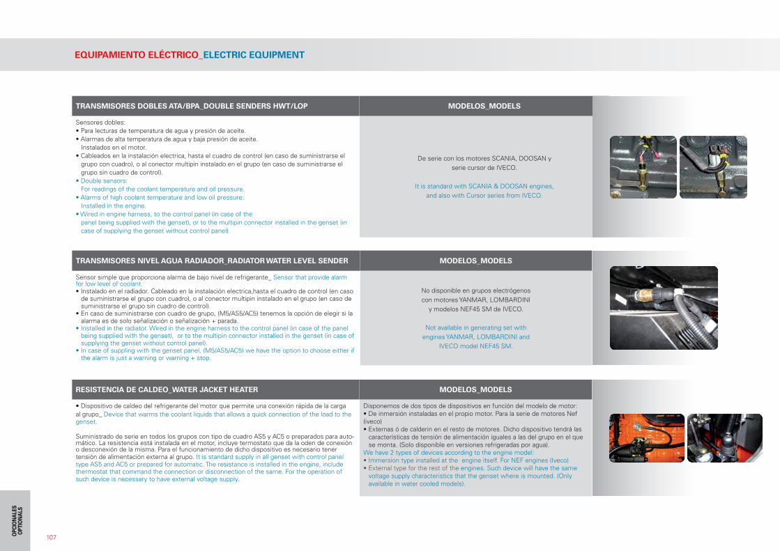
107
TRANSMISORES DOBLES ATA/BPA_DOUBLE SENDERS HWT/LOP MODELOS_MODELS
Sensores dobles:• Para lecturas de temperatura de agua y presión de aceite.• Alarmas de alta temperatura de agua y baja presión de aceite.
Instalados en el motor.• Cableados en la instalación electrica, hasta el cuadro de control (en caso de suministrarse el
grupo con cuadro), o al conector multipin instalado en el grupo (en caso de suministrarse el grupo sin cuadro de control).
• Double sensors:For readings of the coolant temperature and oil pressure.
• Alarms of high coolant temperature and low oil pressure:Installed in the engine.
• Wired in engine harness, to the control panel (in case of thepanel being supplied with the genset), or to the multipin connector installed in the genset (in case of supplying the genset without control panel).
De serie con los motores SCANIA, DOOSAN yserie cursor de IVECO.
It is standard with SCANIA & DOOSAN engines,and also with Cursor series from IVECO.
TRANSMISORES NIVEL AGUA RADIADOR_RADIATOR WATER LEVEL SENDER MODELOS_MODELS
Sensor simple que proporciona alarma de bajo nivel de refrigerante_ Sensor that provide alarm for low level of coolant.• Instalado en el radiador. Cableado en la instalación electrica,hasta el cuadro de control (en caso
de suministrarse el grupo con cuadro), o al conector multipin instalado en el grupo (en caso de suministrarse el grupo sin cuadro de control).
• En caso de suministrarse con cuadro de grupo, (M5/AS5/AC5) tenemos la opción de elegir si la alarma es de solo señalización o señalización + parada.
• Installed in the radiator. Wired in the engine harness to the control panel (in case of the panel being supplied with the genset), or to the multipin connector installed in the genset (in case of supplying the genset without control panel).
• In case of suppling with the genset panel, (M5/AS5/AC5) we have the option to choose either if the alarm is just a warning or warning + stop.
No disponible en grupos electrógenoscon motores YANMAR, LOMBARDINI
y modelos NEF45 SM de IVECO.
Not available in generating set withengines YANMAR, LOMBARDINI and
IVECO model NEF45 SM.
RESISTENCIA DE CALDEO_WATER JACKET HEATER MODELOS_MODELS
• Dispositivo de caldeo del refrigerante del motor que permite una conexión rápida de la carga al grupo_ Device that warms the coolant liquids that allows a quick connection of the load to the genset.
Suministrado de serie en todos los grupos con tipo de cuadro AS5 y AC5 o preparados para auto-mático. La resistencia está instalada en el motor, incluye termostato que da la oden de conexión o desconexión de la misma. Para el funcionamiento de dicho dispositivo es necesario tener tensión de alimentación externa al grupo. It is standard supply in all genset with control panel type AS5 and AC5 or prepared for automatic. The resistance is installed in the engine, include thermostat that command the connection or disconnection of the same. For the operation of such device is necessary to have external voltage supply.
Disponemos de dos tipos de dispositivos en función del modelo de motor:• De inmersión instaladas en el propio motor. Para la serie de motores Nef (iveco)• Externas ó de calderin en el resto de motores. Dicho dispositivo tendrá las
características de tensión de alimentación iguales a las del grupo en el que se monta. (Solo disponible en versiones refrigeradas por agua).
We have 2 types of devices according to the engine model:• Immersion type installed at the engine itself. For NEF engines (Iveco)• External type for the rest of the engines. Such device will have the same
voltage supply characteristics that the genset where is mounted. (Only available in water cooled models).
EQUIPAMIENTO ELÉCTRICO_ELECTRIC EQUIPMENT
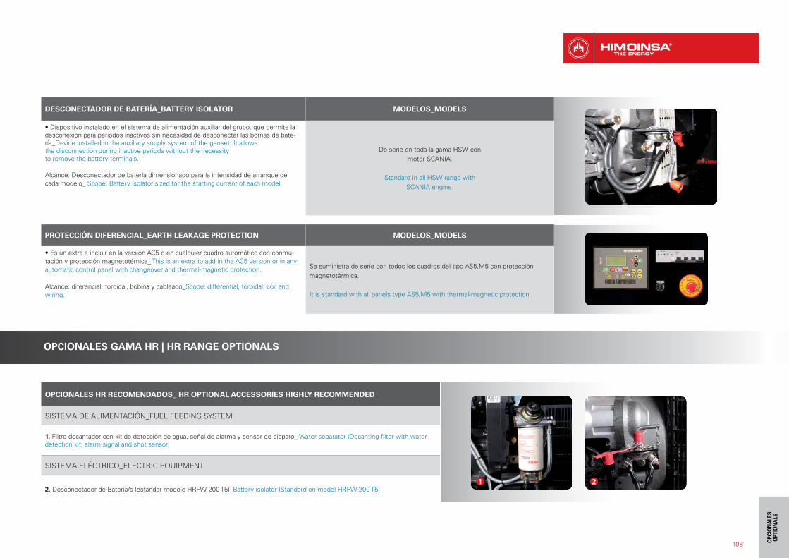
108
DESCONECTADOR DE BATERÍA_BATTERY ISOLATOR MODELOS_MODELS
• Dispositivo instalado en el sistema de alimentación auxiliar del grupo, que permite la desconexión para periodos inactivos sin necesidad de desconectar las bornas de bate-ría_Device installed in the auxiliary supply system of the genset. It allowsthe disconnection during inactive periods without the necessityto remove the battery terminals.
Alcance: Desconectador de batería dimensionado para la intensidad de arranque de cada modelo_ Scope: Battery isolator sized for the starting current of each model.
De serie en toda la gama HSW conmotor SCANIA.
Standard in all HSW range withSCANIA engine.
PROTECCIÓN DIFERENCIAL_EARTH LEAKAGE PROTECTION MODELOS_MODELS
• Es un extra a incluir en la versión AC5 o en cualquier cuadro automático con conmu-tación y protección magnetotémica_ This is an extra to add in the AC5 version or in any automatic control panel with changeover and thermal-magnetic protection.
Alcance: diferencial, toroidal, bobina y cableado_Scope: differential, toroidal, coil and wiring.
Se suministra de serie con todos los cuadros del tipo AS5,M5 con protección magnetotérmica.
It is standard with all panels type AS5,M5 with thermal-magnetic protection.
OPCIONALES GAMA HR | HR RANGE OPTIONALS
OPCIONALES HR RECOMENDADOS_ HR OPTIONAL ACCESSORIES HIGHLY RECOMMENDED
SISTEMA DE ALIMENTACIÓN_FUEL FEEDING SYSTEM
1. Filtro decantador con kit de detección de agua, señal de alarma y sensor de disparo_ Water separator (Decanting filter with water detection kit, alarm signal and shot sensor)
SISTEMA ELÉCTRICO_ELECTRIC EQUIPMENT
2. Desconectador de Batería/s (estándar modelo HRFW 200 T5)_Battery isolator (Standard on model HRFW 200 T5)1 2

DESCRIPCIÓN_DESCRIPTIONTIPO CARROCERÍA Dimensiones con tanque de G.C. largo x ancho x alto CAPACIDAD L.
CANOPY TYPE Dimensions with H.C. fuel tank lenght x width x height CAPACITY L.
Depósitos fabricados en chapa de alta resistencia, preparados para garantizar suministro al grupo al 100% de carga entre 20-24 H._Metal fuel tanks made of high resistance steel plates prepared to guarantee the fuel supply of the genset at 100 % load during 20-24 H.
B10R 2150 x 1024 x 1552 190
D10R 2810 x 1150 x 1940 450
E10R3360 x 1250 x 1975 600
3360 x 1250 x 2187 1100
OPCIONALES HR PLUS_ HR_PLUS OPTIONAL ACCESSORIES
MOTOR_ENGINE
3. Nivel de agua del radiador (estándar modelo HRFW 200 T5)_ Radiator coolant level (standard on model HRFW 200 T5)
ALTERNADOR_ALTERNATOR
4. Imán permanente (en serie HRFW)_Permanent magnet (HRFW serie)
Resistencia anticondensación_Anti-condensation heater
ELECTRÓNICA_ELECTRONICS
Instalaciones para gestión y control de flotas; GSM, GPS,.._Devices for managing and controlling of the fleet; GSM, GPS,
CUADRO DE BASES_DISTRIBUTION BOX
Cuadro de bases auxiliares IP67, con protección magnetotérmica individual_Auxiliary socket box IP67, with individual breaker protection
Acceso directo a bases auxiliares con protección adecuada_ Direct access to auxiliary sockets with suitable protection
CHASIS_CHASSIS
5. Detector de fuga de líquidos_ Liquid leakage detector
SISTEMA DE ALIMENTACIÓN_FUEL FEEDING SYSTEM
6. Kit de Válvula de tres vías y enchufes de conexión para trasiego de combustible_ 3 way valve kit and fast connection fittings for fuel transfer.
ESCAPE_EXHAUST
Apagachispas de seguridad o kit para atmósferas explosivas o ambientes con alto índice de inflamabilidad_Spark arrestor or kit for explosive atmospheres or environ-ments with high flammability
3
4
5
6
109
DEPOSITO GRAN CAPACIDAD GAMA HR | HIGH CAPACITY FUEL TANK HR RANGE