modelling pedestrian interaction with perceptibly ... · vibration serviceability of modern...
TRANSCRIPT

© Faculty of Mechanical Engineering, Belgrade. All rights reserved FME Transactions (2013) 41, 271-278 271
Received: September 2013, Accepted: October 2013 Correspondence to: Dr Stana Živanović School of Engineering, University of Warwick CV4 7AL, Coventry, United Kingdom [email protected]
Hiep V. Dang PhD Student
School of Engineering University of Warwick
United Kingdom
Stana Živanović Assistant Professor
School of Engineering University of Warwick
United Kingdom
Modelling Pedestrian Interaction with Perceptibly Vibrating Footbridges To evaluate the vibration serviceability of footbridge structures most structural engineers use pedestrian force models that are defined for walking on rigid surfaces. This approach is no longer applicable for slender, light-weight and low-frequency structures that are prone to perceptible vibrations under walking excitation. To overcome this issue, it is necessary to understand the pedestrian walking locomotion and how the locomotion process interacts with the vibrating structure. This paper compares three approaches for modelling pedestrian walking over lively structures, and it critically evaluates their suitability for modelling the feedback mechanism between the structure and the pedestrian. The models are evaluated with respect to their capability to reproduce human-like motion as well as to replicate the vibration patterns observed on lively bridges. It has been shown that models used in biomechanics are good candidates for applications in the structural engineering context. Keywords: pedestrian locomotion, lively bridge, vibration, interaction.
1. INTRODUCTION
During walking humans experience side to side, up and down and forward acceleration and decelerations of their body. A simple way to represent the human movement is to observe motion of the body centre of mass (BCOM) in three-dimensional space. While walking BCOM is usually located within the pelvis and it moves in an oscillatory fashion for a few centimetres in both the vertical and horizontal-lateral directions as shown in Figure 1 [1]. As a result of this movement, people induce a three-dimensional force into the supporting structure, with the strongest component of the force acting in the vertical direction.
b
a
c
Figure 1. Displacement of BCOM during two walking steps (not to scale). a) Lateral displacement, b) vertical displacement, and c) combined displacements of a and b projected onto a plane perpendicular to the plane of progression (after [1]).
An example of the vertical ground reaction force (GRF) generated by a person during different phases of walking [2] as well as the corresponding trajectory of the BCOM in the sagittal plane are shown in Figure 2. The two feet often generate slightly different forces due to slight asymmetry in the human body. As a result, the GRF pattern is near-periodic, resulting in some dissipation of the energy around main harmonics [3].
Figure 2. Vertical GRF and BCOM’s trajectory during walking (partially recreated from [2]).
Vibration serviceability of modern footbridges under pedestrian traffic is usually of concern if the structure has one of the vibration modes in the frequency range typical of normal human pacing rate, i.e. 1.5-2.4Hz [4, 5]. Since a single mode is normally of interest, the bridge can be modelled as a single-degree-of-freedom system. Walking at a pacing frequency close to the frequency of the structure increases the incidence of resonance caused by the first harmonic of the walking force, and therefore it can result in development of high-level vibration response. To predict the structural vibration levels reliably, it is necessary to model the first harmonic of the walking force accurately. Many
272 ▪ VOL. 41, No 4, 2013 FME Transactions
models of the vertical GRF exist in the literature, starting from the design guidelines that account for a dominant frequency line in the spectrum only [6-8] to the recently developed models that account for dissipation of the energy [3,9,10]. However, all these models assume that the walking takes place on a “rigid” (i.e. imperceptibly vibrating) surface. As a result, these models cannot predict vibration response of slender, perceptibly vibrating, structures on which the pedestrian-structure dynamic interaction takes place [11,12]. This traditional approach of modelling the pedestrian-induced force independently from the structural vibration is no longer applicable for slender, light-weight and low-frequency structures that are prone to perceptible vibrations under walking excitation. To improve the models for vibration serviceability evaluation of footbridge structures it is necessary to understand the pedestrian walking locomotion as well as the ways how the locomotion process interacts with the vibrating structure.
Several ideas to account for pedestrian structure interaction emerged in last few years motivated by developments in modelling human locomotion in biomechanics, as well as modelling of human-structure interaction for passive (i.e. standing or sitting) humans [13,14]. These models, however, have to be developed further before being ready for use in the design practice. Critical evaluation of these models for use in the civil engineering context is of particular interest, as well as clear definition of the parameter space relevant for structural engineering applications.
This paper presents key features of the two interaction models and compares their performance against a traditional non-interactive model representing walking on a rigid surface. The three models are critically evaluated with respect to their capability to reproduce kinematic and kinetic features of human walking as well as to replicate the vibration patterns observed on a lively bridge. Only walking at a pacing rate that matches the natural frequency of the structure is investigated, since this situation causes development of strong vibrations which are a prerequisite for development of the human-structure interaction.
The paper starts with a description of a lively footbridge and experimental data acquired during single person walking tests. Then the three pedestrian models are described, before proceeding to simulating the structural response and comparing the performance of the models. At the end, conclusions are presented.
2. STRUCTURAL DESCRIPTION AND WALKING
TESTS
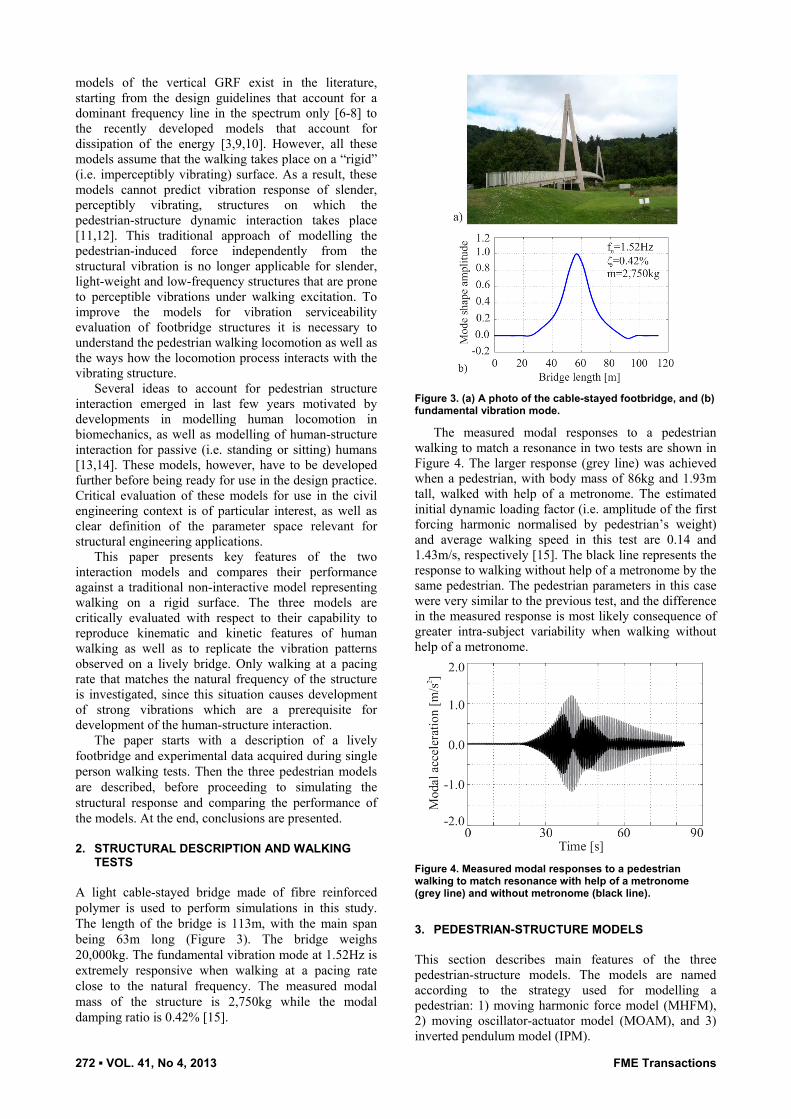
A light cable-stayed bridge made of fibre reinforced polymer is used to perform simulations in this study. The length of the bridge is 113m, with the main span being 63m long (Figure 3). The bridge weighs 20,000kg. The fundamental vibration mode at 1.52Hz is extremely responsive when walking at a pacing rate close to the natural frequency. The measured modal mass of the structure is 2,750kg while the modal damping ratio is 0.42% [15].
Figure 3. (a) A photo of the cable-stayed footbridge, and (b) fundamental vibration mode.
The measured modal responses to a pedestrian walking to match a resonance in two tests are shown in Figure 4. The larger response (grey line) was achieved when a pedestrian, with body mass of 86kg and 1.93m tall, walked with help of a metronome. The estimated initial dynamic loading factor (i.e. amplitude of the first forcing harmonic normalised by pedestrian’s weight) and average walking speed in this test are 0.14 and 1.43m/s, respectively [15]. The black line represents the response to walking without help of a metronome by the same pedestrian. The pedestrian parameters in this case were very similar to the previous test, and the difference in the measured response is most likely consequence of greater intra-subject variability when walking without help of a metronome.
Figure 4. Measured modal responses to a pedestrian walking to match resonance with help of a metronome (grey line) and without metronome (black line).
3. PEDESTRIAN-STRUCTURE MODELS
This section describes main features of the three pedestrian-structure models. The models are named according to the strategy used for modelling a pedestrian: 1) moving harmonic force model (MHFM), 2) moving oscillator-actuator model (MOAM), and 3) inverted pendulum model (IPM).

FME Transactions VOL. 41, No 4, 2013 ▪ 273
3.1 Moving harmonic force model
MHFM is a model on which traditional vibration serviceability assessment is based. Pedestrian is represented as a harmonic force crossing the bridge at a constant speed. The force is independent from the vibration of the bridge. The modal force ( )F t is
obtained after weighting the harmonic force ( )F th
by a
mode shape of interest ( ) ( )x vt :
( ) ( ) ( ) ( ) sin(2 ) ( )F t F t vt DLF W f t vt h p (1)
where W is the pedestrian weight, DLF is the dynamic
load factor, fp
is the pacing frequency, x is the
pedestrian’s position along the bridge, v is the pedestrian’s speed and t is the time elapsed since the pedestrian entered the bridge. To calculate the modal vibration response of the structure at the midspan, the well-known equation of motion has to be solved:
2( ) 2 ( ) ( ) ( )my t m y t m y t F t n n (2)
where m, n and are the modal mass, natural
frequency and damping ratio of the vibration mode of interest, while ( )y t , ( )y t and ( )y t are the modal
acceleration, velocity and displacement of the structure, respectively. 3.2 Moving oscillator-actuator model MOAM represents a pedestrian’s body as a dynamic entity (i.e. mass-spring-damper oscillator) crossing the bridge at a constant speed. As a consequence the pedestrian-structure system is represented by a two degree-of-freedom (DOF) model whose dynamic properties are changing slightly as the pedestrian is crossing the bridge. To account for the muscle action of the pedestrian, an actuator is introduced. The actuator generates harmonic force acting on both pedestrian and structural DOFs [14]. The system of two differential equations coupling the pedestrian and structural vibration can be written as:
0 ( )
0 ( )
m y t
m y t
p p
2 ( )2 2 2
( )2 2
y tm m x m x
y tm x m
n p p np p p np
pp p np p p np
(3)
2 2 2 2
2 2
( ) ( )
( ) ( )
m m x m x y t F t
y t F tm x m
n p np p np
p hp np p np
where p
m , np
and p
are the mass, natural
frequency and damping ratio of the pedestrian, while
( )y tp , ( )y t
p and ( )y t
pare the acceleration, velocity and
displacement of the pedestrian’s centre of mass,
respectively. The natural frequency in radians/s np
can
be transferred into the natural frequency fnp
expressed
in Hz using the well-known relationship 2 f np np
.
The forcing terms on the right hand side are based on dynamic loading factor DLFa of the actuator force. The remaining variables in the equation have been introduced previously.
Coupling between the two DOFs in this equation is a means of accounting for interaction between the pedestrian and structural vibration. A particular challenge when using this model is the choice of the pedestrian parameters; these parameters are yet to be calibrated against the experimental data. In the absence of more definitive guidance, some data from the literature related to bouncing activity will be used in the context of this paper.
3.3 Inverted pendulum model
IPM is the simplest bipedal walking model of a pedestrian. The model consists of a point mass at the top
of two rigid and massless legs [16]. The point mass p
m
represents the mass of the pedestrian, while l is the distance between the BCOM and the foot (Figure 5). The model is set in motion by specifying the angle of
attack 0
(Figure 5) and the initial forward speed of the
point mass. After a step is completed, an upwards impulse has to be applied to prevent falling of the mass [13]. To simplify the modelling, the initial conditions are reset at the beginning of a new step.
X
Y0
L
m
y(t)oxx
l
00
p
y(t)
Figure 5. Inverted pendulum model “walking” across a structure.
The system of differential equations describing the structural and pedestrian movement can be derived using Lagrangian approach:
cos ( )( ) ( ) ( )
tt g x y t
l
(4)
2 2
2 2 2
( )sin ( ) ( ) 2 (2 ) ( )
(2 ) ( ) ( ) sin ( ) ( ) sin ( )
m m x t y t m f y t
m f y t x m g t l t t
p n
n p
(5)
where g is the acceleration of gravity, , and are the leg angle measured from the horizontal reference, angular speed and acceleration, respectively, while all other parameters have been described previously. Differently from MOAM where the interaction is accounted for by modelling the pedestrian body dynamics, the IPM accounts for interaction through timing of the steps. This timing is influenced by the structural vibration.
4. SIMULATIONS ON LIVELY FOOTBRIDGE
This section compares the force and trajectory of BCOM as generated by different models while walking
274 ▪ VOL. 41, No 4, 2013 FME Transactions
over the bridge shown in Figure 3. In addition, the response of the structure calculated in each model is compared with the experimental values shown in Figure 4. Before performing simulations, the choice of parameters to be used in each model is explained first. 4.1 Choice of input parameters
The input parameters for modelling the bridge DOF are based on experimentally acquired properties of the first vibration mode. These are natural frequencies of 1.52Hz, damping ratio of 0.42%, modal mass of 2,750kg and mode shape represented in Figure 3b.
The input parameters related to pedestrian in the MHFM are also straight forward, since they are based on the experimental data explained in Section 2:
0.14DLF , 86W kg, pedestrian’s average speed
1.43v m/s, and pacing frequency 1.52f p
Hz.
In MOAM, two choices of the oscillator properties and the dynamic loading factor of the actuator force DLFa are made. First choice is based on studies of dynamic properties of bouncing people [17]. The pedestrian natural frequency equal to that of an average
bouncing person ( 2.3f np
Hz) is chosen, while
damping and DLFa identified for bouncing people (approximately 25% and 0.3, respectively) are reduced three times (to 8% and 0.1, respectively) to account for the fact that the walking activity results in a shorter contact time and a less severe dynamic loading compared to the bouncing. Given that the natural frequency of the pedestrian is likely to have strong influence on the results, similarly to the effects of tuned mass dampers, second choice of parameters is made so that the pedestrian frequency matches the structural
frequency (i.e. 1.52f np
Hz) while the damping ratio
and DLFa are kept as before. The two sets of pedestrian parameters will be referred to as MOAM1 and MOAM2.
Finally, for the implementation of IPM the leg length is chosen as 1.216l m (this corresponds to the
pedestrian height of 1.93m). Initial conditions 0x and 0
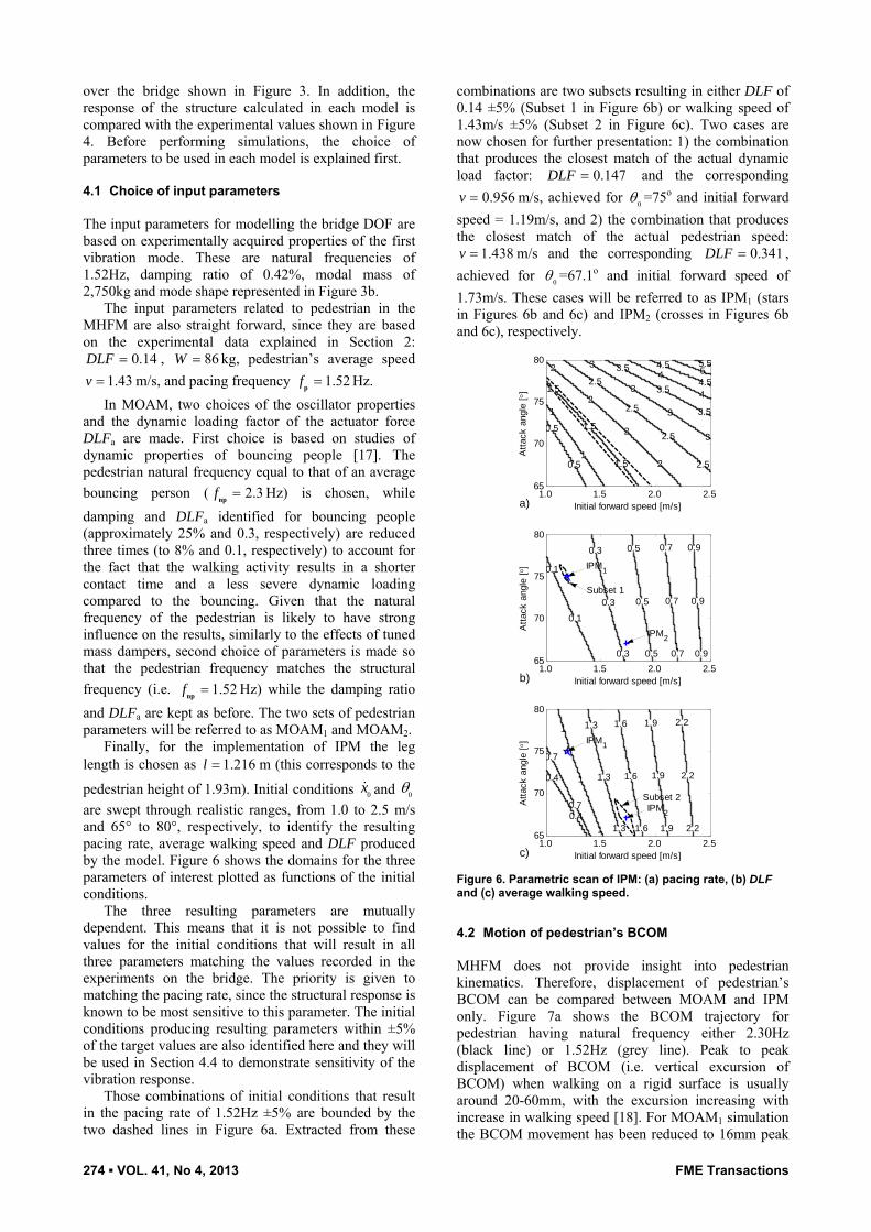
are swept through realistic ranges, from 1.0 to 2.5 m/s and 65° to 80°, respectively, to identify the resulting pacing rate, average walking speed and DLF produced by the model. Figure 6 shows the domains for the three parameters of interest plotted as functions of the initial conditions.
The three resulting parameters are mutually dependent. This means that it is not possible to find values for the initial conditions that will result in all three parameters matching the values recorded in the experiments on the bridge. The priority is given to matching the pacing rate, since the structural response is known to be most sensitive to this parameter. The initial conditions producing resulting parameters within ±5% of the target values are also identified here and they will be used in Section 4.4 to demonstrate sensitivity of the vibration response.
Those combinations of initial conditions that result in the pacing rate of 1.52Hz ±5% are bounded by the two dashed lines in Figure 6a. Extracted from these
combinations are two subsets resulting in either DLF of 0.14 ±5% (Subset 1 in Figure 6b) or walking speed of 1.43m/s ±5% (Subset 2 in Figure 6c). Two cases are now chosen for further presentation: 1) the combination that produces the closest match of the actual dynamic load factor: 0.147DLF and the corresponding
0.956v m/s, achieved for 0
=75o and initial forward
speed = 1.19m/s, and 2) the combination that produces the closest match of the actual pedestrian speed:
1.438v m/s and the corresponding 0.341DLF ,
achieved for 0
=67.1o and initial forward speed of
1.73m/s. These cases will be referred to as IPM1 (stars in Figures 6b and 6c) and IPM2 (crosses in Figures 6b and 6c), respectively.
1.0 1.5 2.0 2.5 65
70
75
80
0.5
0.5
1
1
1.5
1.5
1.5
2
2
2
2
2.5
2.5
2.5
2.5
3
3
3
3
3.5
3.5
3.5
4
4
4.5
4.555.5
Initial forward speed [m/s]
Att
ack
angl
e [
]
a)
1.0 1.5 2.0 2.5 65
70
75
80
0.1
0.1
0.3
0.3
0.3
0.5
0.5
0.5
0.7
0.7
0.7
0.9
0.9
0.9
Initial forward speed [m/s]
Att
ack
angl
e [
]
b)
IPM1
IPM2
Subset 1
1.0 1.5 2.0 2.5 65
70
75
80
0.4
0.4
0.7
0.7
1
1
1
1.3
1.3
1.3
1.6
1.6
1.6
1.9
1.9
1.9
2.2
2.2
2.2
Initial forward speed [m/s]
Att
ack
angl
e [
]
c)
IPM1
IPM2
Subset 2
Figure 6. Parametric scan of IPM: (a) pacing rate, (b) DLF and (c) average walking speed.
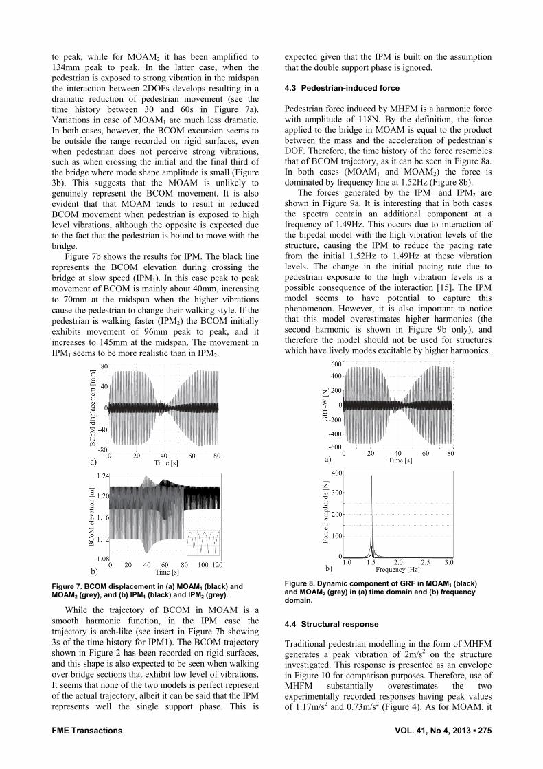
4.2 Motion of pedestrian’s BCOM MHFM does not provide insight into pedestrian kinematics. Therefore, displacement of pedestrian’s BCOM can be compared between MOAM and IPM only. Figure 7a shows the BCOM trajectory for pedestrian having natural frequency either 2.30Hz (black line) or 1.52Hz (grey line). Peak to peak displacement of BCOM (i.e. vertical excursion of BCOM) when walking on a rigid surface is usually around 20-60mm, with the excursion increasing with increase in walking speed [18]. For MOAM1 simulation the BCOM movement has been reduced to 16mm peak
FME Transactions VOL. 41, No 4, 2013 ▪ 275
to peak, while for MOAM2 it has been amplified to 134mm peak to peak. In the latter case, when the pedestrian is exposed to strong vibration in the midspan the interaction between 2DOFs develops resulting in a dramatic reduction of pedestrian movement (see the time history between 30 and 60s in Figure 7a). Variations in case of MOAM1 are much less dramatic. In both cases, however, the BCOM excursion seems to be outside the range recorded on rigid surfaces, even when pedestrian does not perceive strong vibrations, such as when crossing the initial and the final third of the bridge where mode shape amplitude is small (Figure 3b). This suggests that the MOAM is unlikely to genuinely represent the BCOM movement. It is also evident that that MOAM tends to result in reduced BCOM movement when pedestrian is exposed to high level vibrations, although the opposite is expected due to the fact that the pedestrian is bound to move with the bridge.
Figure 7b shows the results for IPM. The black line represents the BCOM elevation during crossing the bridge at slow speed (IPM1). In this case peak to peak movement of BCOM is mainly about 40mm, increasing to 70mm at the midspan when the higher vibrations cause the pedestrian to change their walking style. If the pedestrian is walking faster (IPM2) the BCOM initially exhibits movement of 96mm peak to peak, and it increases to 145mm at the midspan. The movement in IPM1 seems to be more realistic than in IPM2.
Figure 7. BCOM displacement in (a) MOAM1 (black) and MOAM2 (grey), and (b) IPM1 (black) and IPM2 (grey).
While the trajectory of BCOM in MOAM is a smooth harmonic function, in the IPM case the trajectory is arch-like (see insert in Figure 7b showing 3s of the time history for IPM1). The BCOM trajectory shown in Figure 2 has been recorded on rigid surfaces, and this shape is also expected to be seen when walking over bridge sections that exhibit low level of vibrations. It seems that none of the two models is perfect represent of the actual trajectory, albeit it can be said that the IPM represents well the single support phase. This is
expected given that the IPM is built on the assumption that the double support phase is ignored.
4.3 Pedestrian-induced force
Pedestrian force induced by MHFM is a harmonic force with amplitude of 118N. By the definition, the force applied to the bridge in MOAM is equal to the product between the mass and the acceleration of pedestrian’s DOF. Therefore, the time history of the force resembles that of BCOM trajectory, as it can be seen in Figure 8a. In both cases (MOAM1 and MOAM2) the force is dominated by frequency line at 1.52Hz (Figure 8b).
The forces generated by the IPM1 and IPM2 are shown in Figure 9a. It is interesting that in both cases the spectra contain an additional component at a frequency of 1.49Hz. This occurs due to interaction of the bipedal model with the high vibration levels of the structure, causing the IPM to reduce the pacing rate from the initial 1.52Hz to 1.49Hz at these vibration levels. The change in the initial pacing rate due to pedestrian exposure to the high vibration levels is a possible consequence of the interaction [15]. The IPM model seems to have potential to capture this phenomenon. However, it is also important to notice that this model overestimates higher harmonics (the second harmonic is shown in Figure 9b only), and therefore the model should not be used for structures which have lively modes excitable by higher harmonics.
Figure 8. Dynamic component of GRF in MOAM1 (black) and MOAM2 (grey) in (a) time domain and (b) frequency domain.
4.4 Structural response Traditional pedestrian modelling in the form of MHFM generates a peak vibration of 2m/s2 on the structure investigated. This response is presented as an envelope in Figure 10 for comparison purposes. Therefore, use of MHFM substantially overestimates the two experimentally recorded responses having peak values of 1.17m/s2 and 0.73m/s2 (Figure 4). As for MOAM, it

276 ▪ VOL. 41, No 4, 2013 FME Transactions
is expected that the dynamics of the pedestrian is an important factor that determines the extent of the interaction. This can be seen in Figure 10a in which two sets of parameters used in the model produce quite different peak responses of 0.70m/s2 and 1.72m/s2.
As for IPM, two simulations result in peak responses of 1.44m/s2 and 2.07m/s2 (Figure 10b). Although both IPM simulations overestimate the measured responses, it should be noted that the simulated response is sensitive to the initial conditions specified.
Figure 9. GRF in IPM1 (black) and IPM2 (grey) in (a) time domain and (b) frequency domain. Impulses are omitted from Figure 9a for clarity.
Figure 10. Acceleration response using (a) MOAM1 (black) and MOAM2 (grey) and (b) IPM1 (black, 120s) and IPM2 (grey, 80s). The envelopes represent the response to MHFM.
When using combination of initial conditions within Subsets 1 and 2 (Figures 6b and 6c) for simulation of structural response, the peak response ranges between
0.69m/s2 and 4.24m/s2. Envelopes of the extreme responses calculated in Subset 1 and Subset 2 are shown in Figures 11a and 11b, respectively. Cumulative distribution functions of the peak response for all combinations of parameters within either subset are plotted in Figure 11c. It can be seen that the calculated range of peak response includes the experimental results reported in Figure 4 and it also includes an absolute maximum response of 2.2m/s2 measured on the bridge under single person excitation [19].
It is interesting that on this bridge the peak response of 2m/s2 calculated using traditional MHFM is not very different from the absolute maximum measured (2.2m/s2), suggesting that the match is good. However, it is misleading to base vibration serviceability assessment on a single response value, given large variations in the dynamic excitation potential within a pedestrian population, and any vibration prediction should be linked to probability of its occurrence.
Figures 10 and 11 show that MOAM and IPM have potential to represent a range of pedestrians under a range of different conditions. However, before being able to do modelling with confidence, it is necessary to calibrate the models against an extensive set of experimental data. Unfortunately, this data set is currently not available and should be subject of future experimental research.
0 20 40 60 80 100 120-5-4-3-2-1012345
Time [s]
Acc
eler
atio
n [m
/s2 ]
a)
0 20 40 60 80-5-4-3-2-1012345
Time [s]
Acc
eler
atio
n [m
/s2 ]
b)
0.5 1.5 2.5 3.5 4.5 0.0
0.2
0.4
0.6
0.8
1.0
Peak response [m/s2]
CD
F
c) Figure 11. Maximum (solid) and minimum (dashed) of structural response in simulations of IPM using combinations of parameters from (a) Subset 1 and (b) Subset 2. (c) Cumulative distribution function of peak response for all simulations from Subset 1 (solid line) and Subset 2 (dashed line).

FME Transactions VOL. 41, No 4, 2013 ▪ 277
5. CONCLUSIONS
Main conclusions of this study can be listed as follows:
Traditional MHFM cannot account for human-structure interaction. To estimate vibration response of slender lively structures reliably, models that account for human-structure interaction should be developed.
Models based on human body dynamics and human stepping behaviour have potential for accounting for pedestrian-structure interaction.
IPM replicates the kinematics of BCOM more closely than MOAM.
The interaction simulated by IPM results in a change of the pacing frequency, which is believed to be one of ways in which a pedestrian interacts with structural vibration.
The responses using both IPM and MOAM are sensitive to a number of input parameters. It is necessary to calibrate these models against experimental data before recommending use of either model in the design practice.
ACKNOWLEDGEMENTS
This research work was supported by the UK Engineering and Physical Sciences Research Council [grant number EP/I03839X/1: Pedestrian Interaction with Lively Low-Frequency Structures]. The first author was also supported by the Warwick Postgraduate Research Scholarship.
REFERENCES
[1] Inman, V. T., Ralston, H. J. and Todd, F.: Human locomotion. In: Human Walking, edited by J. Rose and J. G. Gamble. Williams & Wilkins, Baltimore, 1994.
[2] Inman, V. T., Ralston, H. and Todd, F.: Human walking. Edwin Mellen Press Ltd., 1980.
[3] Brownjohn, J.M.W., Pavic, A. and Omenzetter, P.: A spectral density approach for modelling continuous vertical forces on pedestrian structures due to walking, Canadian Journal of Civil Engineering, Vol. 31, pp. 65-77, 2004.
[4] Živanović, S., Pavic, A. and Reynolds, P.: Vibration serviceability of footbridges under human-induced excitation: a literature review, Journal of Sound and Vibration, Vol. 279, pp. 1-74, 2005.
[5] Racic, V., Pavic, A. and Brownjohn, J.M.W.: Experimental identification and analytical modeling of human walking forces: literature review, Journal of Sound and Vibration, Vol. 326, pp. 1-49, 2009.
[6] UK National Annex to Eurocode 1: Actions on structures—Part 2: Traffic loads on bridges. NA to BS EN 1991-2:2003, British Standards Institution, 2008.
[7] Bases for design of structures—Serviceability of buildings and walkways against vibration. ISO 10137:2007, International Organization for Standardization, 2007.
[8] Footbridges: Assessment of Vibrational Behaviour of Footbridges under Pedestrian Loading, technical guide, Service d’Etudes Techniques des Routes et Autoroutes, Paris, 2006.
[9] Živanović, S., Pavic, A. and Reynolds, P.: Probability based prediction of multi-mode vibration response to walking excitation, Engineering Structures, Vol. 29, pp. 942-954, 2007.
[10] Racic, V. and Brownjohn, J.M.W.: Stochastic model of near-periodic vertical loads due to humans walking, Advanced Engineering Informatics, Vol. 25, pp. 259–275, 2011.
[11] Živanović, S., Pavic, A. and Ingólfsson, E.T.: Modelling spatially unrestricted pedestrian traffic on footbridges, Journal of Structural Engineering, Vol. 136, pp. 1296-1308, 2010.
[12] Piccardo, G. and Tubino, F.: Equivalent spectral model and maximum dynamic response for the serviceability analysis of footbridges, Engineering Structures, Vol. 40, pp. 445-456, 2012.
[13] Bocian, M., Macdonald, J.H.G. and Burn, J.F.: Biomechanically-inspired modelling of pedestrian-induced vertical self-excited forces, Journal of Bridge Engineering, in press, 2013.
[14] Alexander, N.A.: Theoretical treatment of crowd-structure interaction dynamics, Structures and Buildings, Vol. 159, pp. 329-338, 2006.
[15] Živanović, S., Pavic, A. and Reynolds, P.: Human-structure dynamic interaction in footbridges, Proceedings of the Institution of Civil Engineers: Bridge Engineering, Vol. 158, pp. 165-177, 2005.
[16] Saunders, J.B.D.M., Inman, V.T. and Eberhart, H.D.: The major determinants in normal and pathological gait, Journal of Bone and Joint Surgery, Vol. 35, pp. 543-58, 1953.
[17] Dougill, J.W., Wright, J.R., Parkhouse, J.G. and Harrison, R.E.: Human structure interaction during rhythmic bobbing, The Structural Engineer, Vol. 84, pp. 32-39, 2006.
[18] Gard, S.A., Miff, S.C. and Kuo, A.D.: Comparison of kinematic and kinetic methods for computing the vertical motion of the body center of mass during walking, Human Movement Science, Vol. 22, pp. 597–610, 2004.
[19] Cadei, J. and Startford, T.: The design, construction and in-service performance of the all-composite Aberfeldy footbridge, in: Proceedings of Advanced Polymer Composites for Structural Applications in Construction, Thomas Telford, London, 2002.
МОДЕЛИРАЊЕ ИНТЕРАКЦИЈЕ ИЗМЕЂУ
ПЕШАКА И ПЕШАЧКОГ МОСТА СА ПРИМЕТНИМ ВИБРАЦИЈАМА

278 ▪ VOL. 41, No 4, 2013 FME Transactions
Hiep V. Dang, Stana Živanović
У циљу евалуације ваљаности вибрација код конструкције пешачких мостова већина конструктора који пројектују мостове користе моделе сила код пешака које се одређују за ходање по крутој површини. Овај метод се више не користи за конструкције које су витке, лаке и са малим фреквенцијама а које су подложне приметним вибрацијама које побуђује ходање. У циљу превазилажења овог проблема неопходно је разумети како се пешак креће и каква је интеракција
између процеса кретања и конструкције која вибрира.
Овај рад приказује три методе моделовања кретања пешака по нестационарној конструкцији и врши критичку евалуацију погодности таквих конструкција за моделовање механизма повратне спреге између конструкције и пешака. Евалуација модела је извршена с обзиром на њихову способност да репродукују људско кретање као и вибрације регистроване на нестационарним мостовима. Показано је да су модели који се користе у биомеханици погодни за примену у контексту конструкција.