modelling candu fuel element and bundle … fuel 2010.pdf · modelling candu fuel element and...
TRANSCRIPT

11th
International Conference on CANDU Fuel
Sheraton Fallsview Hotel and Conference Centre
Niagara Falls, Ontario, Canada, 2010 October 17-20
MODELLING CANDU FUEL ELEMENT AND BUNDLE BEHAVIOUR FOR IN- AND
OUT-REACTOR PERFORMANCE OF INTACT AND DEFECTIVE FUEL
K. Shaheen*, A.D. Quastel, J.S. Bell, B.J. Lewis, W.T. Thompson, and E.C. Corcoran
Department of Chemistry and Chemical Engineering
Royal Military College of Canada
17000 Station Forces, Kingston, Ontario, Canada K7K 7B4
*Corresponding Author: Tel – 613 541 6000 x 6147, E-mail – [email protected]
ABSTRACT – A proposed platform-based fuel performance code integrates treatments for intact fuel performance
and defective fuel oxidation. The intact fuel performance code is verified against the ELESTRES and ELESIM
industry-standard toolset for heat transport, fission gas diffusion, and deformation and interaction of the pellet and
sheath. The oxidation model integrates equilibrium thermodynamics into oxygen transport equations and is validated
against coulometric titration data from Chalk River Laboratories. Ongoing work aims to incorporate the intact fuel
performance model into a bundle heat transport and deformation model, and to apply the oxidation to the design and
analysis of an out-reactor instrumented fuel oxidation experiment.
1. Introduction
Industry codes such as ELESTRES, ELOCA, and BOW are used to simulate fuel behaviour. The
goal of the current work is to test the ability of platform-based models as tools to predict fuel
performance and design fuel behavior experiments.
Nuclear fuel performance in an individual element is dependent on a number of inter-related
phenomena, including fission heating and heat transport, fission gas release from the evolving
uranium dioxide fuel grains and diffusion to the fuel-to-sheath gap, and material deformation of
both the fuel and the Zircaloy sheath. Bundle behavior involves the bowing of individual
elements, which is primarily thermally induced [1,2], as well as the effects of contact between
different elements and the elements and the bundle endplates. With the rare incidence of a sheath
defect, coolant flow into the fuel element results in fuel oxidation, which in turn affects the
fission gas release from the fuel element [3] and the fuel thermal performance [4].
2. Model Development
Three models are described in this work: (i) A single-element fuel performance code is
developed to account for heat and mass transport for intact fuel analysis (Section 2.1); (ii) a
bowing model is further considered, based on a beam approximation, to predict the overall
deflection of an element due to an external load (Section 2.2); and (iii) a defective fuel oxidation
model is applied to simulate fuel oxidation behavior in a proposed out-reactor loop experiment at
the Stern Laboratories (Section 2.3). The latter out-reactor loop test is proposed to help validate a
previously-developed fuel oxidation model that can be eventually used and implemented in the
fuel performance code in order to mechanistically predict defective fuel element behavior. The
fuel performance and fuel oxidation models specifically advance the work of Morgan [5] and
Higgs et. al. [6], respectively.

11th
International Conference on CANDU Fuel
Sheraton Fallsview Hotel and Conference Centre
Niagara Falls, Ontario, Canada, 2010 October 17-20
The overall objective of the current work is to develop these models on a commercial numerical
platform (COMSOL Multiphysics) so that the individual phenomena/codes describing fuel
element performance, fuel element/bundle bowing, and defective fuel behaviour can be linked
into a single multiphysics tool.
2.1 Intact fuel element performance model
2.1.1 Heat generation and transport
The heat conduction equation in the fuel element is:
po
p
p
p
lin
p arrIaI
a
a
PTk
t
TC
9187.83exp6247.0
2 12
(1)
where r is the radial coordinate, t is time, and T is temperature. The heat generation due to fission
is given by the term
p
p
p
p
lin arrIaI
a
a
P
9187.83exp6247.0
20
1
2
, where Plin is the element power rating
(kW m-1
), ap is the pellet radius, κ is the inverse neutron diffusion length, the Bessel functions I0
and I1 account for neutron flux depression, and the term par 9187.83exp6247.0 accounts for the
buildup of plutonium on the outer surface of the fuel for an average burnup of 100 MWh kgU-1
.
The heat generation term applies within the fuel pellet but not in the sheath. The terms ρ, Cp, and
k represent density, heat capacity, and thermal conductivity, which vary between the fuel and
sheath as shown in Section 3.
Over time, fuel expansion and sheath creepdown bring the fuel and sheath into contact. Due to
surface roughness, heat transfer from the fuel pellet to the sheath occurs via both gas conduction
and solid-to-solid conduction, for which the coefficients are:
HRa
Pkh
rms
im
solid 21
0
21
(2)
gapgapg
fgas
PTgtRR
kh
101.02735.12405.1
21 (3)
where a0 = 8.6×10⁻³
m0.5
MPa-0.5
, km and kf are the harmonic mean thermal conductivity of the
solids and the thermal conductivity of the gas in the gap, respectively, sissi rtYP is the
interfacial pressure between the fuel and the sheath surfaces (MPa),
mRRRrms 8.022
22
1 is the root-mean-square roughness of the two surfaces, R1 and R2,
and H = 4.4Ys is the Meyer hardness of the Zircaloy sheath (MPa) as a function of the yield
strength of the sheath Ys, given in Section 3. The terms ts and rsi refer to the sheath thickness, and
inner radius, respectively, tg is the gap thickness, g is the temperature jump distance for helium
(for intact fuel), and Tgap and Pgap are the average gap temperature and pressure, respectively.
The temperature at the sheath outer surface is dependent on heat transfer from the coolant:
scso
lincso
hr
PTT
1
2 (4)
Here Tc is the coolant temperature rso is the sheath outer radius, and hsc is the sheath-to-coolant
heat transfer coefficient (5×10⁴ W m
-2 K
-1).

11th
International Conference on CANDU Fuel
Sheraton Fallsview Hotel and Conference Centre
Niagara Falls, Ontario, Canada, 2010 October 17-20
2.1.2 Fission Gas Diffusion and Grain Growth
The fission gas diffusion and release is simulated by treating Xenon as the stable diffusing
species. The release rate to the fuel grain surface is governed the Booth diffusion equation,
which approximates the grains as spheres, as solved analytically by Kidson [7]. For a single
power cycle, the Kidson solution reduces to that of Beck [8]:
1
222
22exp1
6
n
ggg dtDnnB
BR
(5)
where B is the production rate of fission gas atoms, which is given as a function of the fission
rate F to be 0.251 F [9], Dg is the gas diffusion coefficient in the uranium dioxide grain, and dg
is the grain diameter, given by Khoruzii et. al. [10] as:
T
TF
ddk
dt
dd
gg
g
g
5620exp1071.6
1118
max,
(6)
where kg is the grain growth rate term, and dg,max is the limiting grain size. The last term, where
F is the fission rate, accounts for the retarding effect of irradiation on grain growth. As fission
gas atoms are released to the fuel grain surface, they form lenticular bubbles along the grain
boundaries. Upon grain surface saturation, these bubbles percolate to form a diffusion path to the
fuel surface. The pellet release is thus given by the volumetric integral of:
gg
gg
gg
p
aTR
aTRdV
aTR
R610736.1
,0
610736.1 ,
610736.1
22
2222
(7)
where Rg represents the number of atoms released from the grains as determined from the rate in
Equation 5 and the term gaT
610736.1 22 accounts for fission gas saturation on the grain surface [5].
2.1.3 Fuel Pellet Deformation
The strain in the fuel is a sum of thermal strain (εth) [11], densification strain (εdens) [12], gaseous
fission product swelling (εFG) [13], and solid fission product swelling (εFS) [9]. These strains are:
FSFGdensthUO 2
(8)
KTTTT
KTKTTTth
923,10219.110429.210179.199672.0
923273,10391.410705.210802.999734.0312295
3132105
(9)
2310 10867.2exp11067.8506.0exp6.0 Tdens (10)
tFG
)10exp(-8T))-2(2800exp(-0.016T)-(2800108.8
3
1 27-11.7356- (11)
0032.03
1FS (12)
where is the fuel burnup, determined by:
Up
UOlin
Ma
MP
dt
d
02
2
(13)

11th
International Conference on CANDU Fuel
Sheraton Fallsview Hotel and Conference Centre
Niagara Falls, Ontario, Canada, 2010 October 17-20
Here MUO2 and MU are the atomic masses of uranium dioxide and uranium, respectively, and ρ0
is the as-fabricated density of uranium (10.7 g cm-3
). Given a change in the fuel radius from an
initial ap,in to ap, the change in fuel volume is equal to:
laaV inppf 2
,2
(14)
where l is the length of the fuel element.
2.1.4 Sheath Deformation
The thin sheath (inner-radius-to-wall-thickness ratio greater than 10) experiences deformation
due to external coolant pressure and internal fuel expansion. The sheath deformation is a
function of the hoop strain ( s) [14]:
sinitsisi rr , (15)
The hoop strain is the sum of thermal ( th ) [5], elastic ( el ) [14], and creep [15] strains ( cr )
given by:
crelths (16)
K 1270,107.910450.9
K 1270K 1050,10398.910486.1
K 1050,10721.610073.2
63
62
63
TT
TT
TT
th
(17)
21
1 Zrexin
s
si
Zrel PP
t
r
E
(18)
HGF
GF
crcr
4
2 (19)
where EZr, νZr, F, G, and H represent the Young’s modulus, Poisson’s ratio, and Hill anisotropy
parameters for the sheath, respectively. The external coolant pressure Pex is equal to 10.7 MPa,
and the internal pressure can be determined using the ideal gas law:
gapcracks
gapav
FGHe
gasinVV
RTN
nn
PP
(20)
where nHe is the number of helium atoms initially in the fuel-to-sheath gap, nFG is the number of
fission gas atoms released and is equal to Rp as determined in Section 2.1.2. The terms Nav, R,
and Tgap represent Avogadro’s number, the ideal gas constant, and the average temperature in the
fuel-to-sheath gap, respectively. The molar gas density is simply the total number of moles
divided by the total volume in Equation 20 above; i.e.: dishesgapcracksAvFGHe VVVNnn . The
volume occupied by the gas is the sum of the volume of the fuel cracks (Vcrack), fuel-to-sheath
gap (Vgap) and the inter-pellet dishes (Vdish). The crack volume is equal to the change in volume
due to fuel deformation (ΔV) as determined in Section 2.1.3. The dish volume is approximated
assuming a dish depth determined by linear thermal expansion at the fuel centerline using the
thermal strain of Equation 9. The gap volume is a function of the distance left between the fuel
and sheath due to their respective deformations:

11th
International Conference on CANDU Fuel
Sheraton Fallsview Hotel and Conference Centre
Niagara Falls, Ontario, Canada, 2010 October 17-20
larV psigap 22
(21)
Finally, the creep strain (εcr) in Equation 19 is the sum of the strains due to dislocation glide (εd)
and grain boundary glide (εg) as given by [16]:
gdcr (22)
3.5
2 34726exp1088.1
iexin
s
sid PP
t
r
T (23)
TPP
t
r
dGexin
s
si
Zrgs
g
9431exp
11034.6
2
,
6 (24)
where Gs is the shear modulus of the sheath. The term dg,Zr represents the grain size of Zircaloy-
4, and the term σi represents the internal stress field given by [16]:
1
61033.01016.0 iexin
s
si
idZri PPt
rE (25)
2.2 Element Bowing Model
The bowing equation, based on the principle of virtual work [17] is:
0)( V
T
el dVW Fu (26)
where F is the force vector on the beam known from the external loads, u is the displacement
vector (m), el is the elastic strain and is the internal stress of the beam (MPa). The long and
slender geometry of a fuel element allows a beam approximation, i.e. there is no deformation that
occurs in the cross section but an applied force causes lateral deflection (deformation) from the
body’s central axis and torsion of the cross section [17]. The same assumption was made by
AECL and MARTEC in their treatment of an element deformation model [1]. This approach
allows Equation 26 to be expressed as a line integral as shown in Equation 27. Here the external
forces and the internal strain are described by the bending moments in each axis ( zyx MMM ,, ),
the torsion of each axis ( zyx ,, ), the force acting perpendicular to the cross section (N), and
the displacement of the centroid of the cross section ( axiu ) (the path of the cross sections
centroids through body makes up the body’s central axis).
dxs
uN
sM
sM
sMW
L
axixx
zz
y
y
(27)
Due to the construction of a fuel element consisting of the fuel pellets and sheath, by assuming
the pellets can be represented as one cylinder the element can be viewed as two separate beams
which undergo bending based on their individual material properties. However, because the
sheath encases the pellets, the total bending of the element is then the summation of the bending
of both the sheath and the pellets: pse MAMM (28)

11th
International Conference on CANDU Fuel
Sheraton Fallsview Hotel and Conference Centre
Niagara Falls, Ontario, Canada, 2010 October 17-20
Here M is the total bending moment and the superscripts e, s and p refer to the element, sheath
and pellet, respectively, and A is a fitting parameter to experimental data that is less than one.
2.3 Out-Reactor Fuel Oxidation Simulation
A conceptual model of Higgs et. al. [6] was developed to mechanistically describe fuel oxidation
behaviour in defective fuel elements. This model is adapted in this work and subsequently
modified to represent an inner-surface heated and unirradiated fuel element in an out-reactor
loop experiment at the Stern Laboratories. This experiment is specifically planned to help
validate the fuel oxidation model where the experimental conditions can be well-controlled. In
particular, this experiment provides an opportunity to measure the fuel element temperature in an
instrumented element with continued fuel oxidation for normal temperature and pressure
CANDU coolant conditions. A post-test analysis also provides an opportunity to assess the fuel
oxidation end-state of the element. Currently, the mechanistic model of Higgs is adapted to help
design the loop test and assess the amount of fuel oxidation expected for a one and two week
experiment.
In the Higgs mechanistic model, a treatment is considered for both gas phase and solid-state
diffusion, which are controlled by temperature-dependent reactions. Hydrogen (H2) and steam
(H2O) are specifically considered in the model for the out-reactor experiment. Figure 1 depicts an
axial cross section of a test fuel element.
Cracks appear in the fuel pellets due to fuel thermal expansion [18,19]. Below the elastic-plastic
boundary, cracks will initially appear but will later self heal [9,20]. This transition is assumed to
occur at a temperature of 1523 K, though in reality it occurs over a range of temperatures [9].
Figure 1 depicts a deliberate sheath defect which is 1 mm wide (into the page) and 20 mm long in
the axial z-direction, with a possible gap between two pellets under the defect site.
Figure 1: A 2D z-r representation of test fuel pellet.
The generalized mass balance equation for oxygen transport in the fuel matrix is given by
Equation 29:
reactffuu RT
RT
QxxDc
t
xc
2
(29)
where D is the diffusion coefficient of oxygen interstitials as a function of temperature. x is the
11th
International Conference on CANDU Fuel
Sheraton Fallsview Hotel and Conference Centre
Niagara Falls, Ontario, Canada, 2010 October 17-20
oxygen deviation from stoichiometry in the uranium oxide matrix (UO2+x), cu is the molar
density of uranium, R is the universal gas constant, T (K) is temperature, f is the pellet average
ratio of crack area to fuel volume, and Q is the molar effective heat transport. The kinetic
reaction rate, react
fR , for fuel oxidation in moles O or H2 m-2
s-1
is
xxpqcR etureactf 1 (30)
where α is the rate coefficient for the surface-exchange of oxygen at the pellet surface, pt is the
total system pressure of 100 atm, q is the hydrogen mole fraction, x is stoichiometric deviation,
and xe is the equilibrium stoichiometry deviation based on the local oxygen potential of the gas
in the fuel cracks [6]. Hydrogen is contributed to the gas environment in the fuel cracks by the
fuel-oxidation reaction. The cracked fuel is assumed to have a porosity P (ε in Equation 31). The
mass balance for the hydrogen molar concentration, qcg, in the fuel cracks is given by Equation
31, where cg is the total molar concentration of the gas and cDg is the steam diffusivity quantity.
react
ffg
gRqcD
dt
qcd (31)
Equation 31 is applicable only in the domain above the elastic-plastic boundary and only under
the defect site (see dashed lines in Figure 1). For out-reactor analysis, the temperature in the fuel
is determined by Equation 1 setting the heat generation term to zero and setting a boundary
condition at the inner surface of the fuel based on the heating element at the centre.
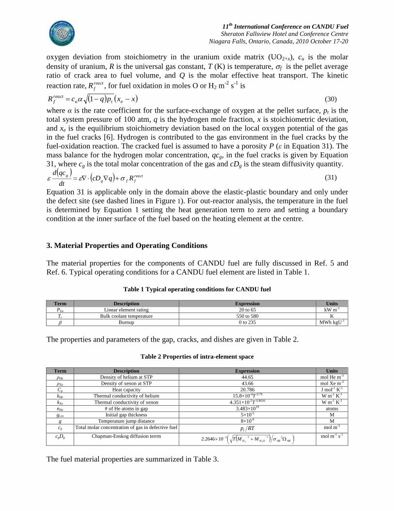
3. Material Properties and Operating Conditions
The material properties for the components of CANDU fuel are fully discussed in Ref. 5 and
Ref. 6. Typical operating conditions for a CANDU fuel element are listed in Table 1.
Table 1 Typical operating conditions for CANDU fuel
Term Description Expression Units
Plin Linear element rating 20 to 65 kW m-1
Tc Bulk coolant temperature 550 to 580 K
Burnup 0 to 235 MWh kgU-1
The properties and parameters of the gap, cracks, and dishes are given in Table 2.
Table 2 Properties of intra-element space
Term Description Expression Units
ρHe Density of helium at STP 44.65 mol He m-3
ρXe Density of xenon at STP 43.66 mol Xe m-3
Cp Heat capacity 20.786 J mol-1 K-1
kHe Thermal conductivity of helium 15.8×10⁻⁴T 0.79 W m-1 K-1
kXe Thermal conductivity of xenon 4.351×10⁻⁵T 0.8616 W m-1 K-1
nHe # of He atoms in gap 3.483×10¹⁹ atoms
gt,in Initial gap thickness 5×10⁻⁵ M
g Temperature jump distance 8×10⁻⁶ M
cg Total molar concentration of gas in defective fuel RTpt mol m-3
cgDg Chapman-Enskog diffusion terrm
ABABOHH MMT2113
22102646.2
mol m-1 s-1
The fuel material properties are summarized in Table 3.

11th
International Conference on CANDU Fuel
Sheraton Fallsview Hotel and Conference Centre
Niagara Falls, Ontario, Canada, 2010 October 17-20
Table 3 Material properties of UO2 fuel
Term Description Expression Units
D Diffusion coefficient of oxygen in UO2 T16400exp105.2 4 m2 s-1
Q* Heat of transport of oxygen in UO2 x2417exp105.3 34 J mol-1
fuel Surface-area-to-volume ratio of UO2
KT
KTKT
KT,
1873 ,0
18731473 ,6825.30025.0908
1473 908
m-1
Oxidation surface exchange coefficient T23500exp365.0 m s-1
cu Molar density 2
4101.4 UO mol U m-3
ρUO2 Density Pth
1109603
kg m-3
P Fuel porosity dens10.0282 -
Cp Heat capacity
(x=0 for intact fuel)
2
4123926
23
295090713910
106334.210542.31102411.841
103461.710951.878056.451743.52
Tx
TTTx
Txx
kJ mol-1 K-1
kUO2 Thermal conductivity (intact fuel)
,213358169.0113358exp102997.5
)31)("06867.0339.0(
285.533exp1285.533exp)285.535(7.297
)'00469.05.6(1
1
23
222
TTT
T
TTT
PT
P
th
kW m-1 K-1
kUO2+x Thermal conductivity (defective fuel) xrppd k 24211 kW m-1 K-1
κ1d Factor for dissolved fission products
TT
0643.009.1
1arctan
0643.009.1
265.3265.3
-
κ1p Factor for precipitated fission products
1001200exp1019.03
019.01
T
-
κ2p Factor for porosity effects PT3105.06.21 -
κ4r Factor for radiation effects
80900exp1
2.01
T
-
k2+x Uncorrected thermal conductivity of UO2 kph + ke kW m-1 K-1
kph Phonon contribution to thermal conductivity 1 BTA kW m-1 K-1
A Phonon-phonon interaction term 5.15.0 86.128194.2381763.1014 xxx K m kW-1
B Phonon-polaron interaction term
155.0,0
155.0,6764.364.02562.02218.03
x
xxxx m kW-1
ke Polaron contribution to thermal conductivity kW m-1 K-1
κ Neutron diffusion length 89.89 + 0.60.68 m-1
Dg Diffusion coefficient for fission gas in UO2
m2 s-1
Dt1 Term included in diffusion coefficient 28-9-1 8702.7-exp105.3+101.5 TDt
-
Dt2 Term included in diffusion coefficient
-
Dt3 Term included in diffusion coefficient TDt 27780exp10010186.1 43 -
dg,in Initial grain radius 1.14×10⁻⁵ M
kg Grain growth rate term T32100exp1046.1 8 m2 s-1
dg,max Limiting grain size T7620exp1023.2 3 M
EUO2 Young’s modulus TPth 411 100915.1111752.211033.2 Pa
νUO2 Poisson’s ratio 0.316 -
14
21
8107
214
10711.5
7.8702exp103.510510432.2
10711.5
t
tt
tt
DF
DD
T
DDF
F
DT
F
DTTD
t
tt
40
5.0
23
34
389
2
108127780exp
10167.81
27780exp10372.2443.35225exp106.7
TT
T 16350exp10024.2
105.287.025
815

11th
International Conference on CANDU Fuel
Sheraton Fallsview Hotel and Conference Centre
Niagara Falls, Ontario, Canada, 2010 October 17-20
The material properties of the sheath are listed in Table 4.
Table 4 Properties of the Zircaloy-4 fuel sheath
Term Description Expression Units
ρ Density dax
LLLL 00 11292.71805 mol m-3
(ΔL/L0)ax Axial thermal expansion term -2313.4 + 9.5043T – 7.0469×10⁻³T 2 + 3.6644×10⁻⁶T 3 -
(ΔL/L0)d Diametral thermal expansion term -2585.8 + 10.142T – 4.8362×10⁻³T 2 + 2.2058×10⁻⁶T 3 -
Cp Heat capacity 23.324 + 8.2402×10⁻³T + 11.6313×10⁻⁷T 2 J mol-1 K-1
k Thermal conductivity 7.51 + 2.09×10⁻²T – 1.45×10⁻⁵T 2 + 7.67×10⁻⁹T 3 W m-1 K-1
EZr Young’s modulus 1.148×10¹¹ – 6×10⁷T Pa
νZr Poisson’s ratio 0.32 -
F,G,H Hill’s anisotropy parameters 0.773, 0.532, 0.195 -
rsi,in Initial sheath inner radius 0.006145 or 0.00722 M
ts,in Initial sheath thickness 4×10⁻⁴ M
dg Grain diameter 3×10⁻⁶ M
Ys Yield Strength sheaths TY 136.65-148695 MPa
By running the fuel performance model using these parameters (Section 4), it is possible to
compare the model predictions to pre-existing data from fuel performance simulations and
experimental data.
4. Numerical Implementation
The equations outlined in Section 2, given the material properties and operating conditions listed
in Section 3, are solved using the commercial platform COMSOL MultiphysicsTM
(henceforth
‘Comsol’) [21]. In Comsol, systems of differential equations are solved on a meshed geometry
using the finite element method.
For the intact fuel element performance model, the two-dimensional geometry is divided into
two domains, representing the fuel and sheath. A moving mesh is used such that the geometry
expands and contracts according to the deformation equations outlined in Section 2.1. The heat
conduction equation in Section 2.1.1 is solved in both domains; however, the source term
accounting for heat generation due to fission is included only in the fuel domain.
The model is able to describe the gap dynamics with the possibility of sheath closure. The
mixed-gas phase and solid-to-solid heat transfer that occurs during contact of the rough surfaces
of the fuel and sheath is simulated as conduction through a 1-μm thermally resistive layer (i.e.,
equal to the surface roughness) using the ‘Identity Pairs’ feature of Comsol. The total heat
transfer coefficient given pellet-sheath contact is equal to hsolid + hgas, the sum of the solid and
gas heat transfer coefficients given in Equations 2 and 3, respectively. The ratio of this new gap
heat transfer coefficient to the original gas heat transfer coefficient is used to scale the gas
thermal conductivity to a new effective thermal conductivity:
TM COMSOL Multiphysics is a trademark of Comsol AB.

11th
International Conference on CANDU Fuel
Sheraton Fallsview Hotel and Conference Centre
Niagara Falls, Ontario, Canada, 2010 October 17-20
fgas
gassolid
eff kh
hhk
(32)
The fission gas diffusion equations in Section 2.1.2 are solved in the fuel domain. Also in the
fuel domain, the fuel strain functions in Section 2.1.3 are entered into a pre-built ‘Axial Stress-
Strain’ application mode in Comsol, which solves for the fuel deformation using internal
functions. In the high temperature plastic region of the fuel, the deformation up is determined by:
22 2
2
UO
pp
UOr
u
t
u
(33)
where 2UO is the density of UO2 and
2UO is given by Equation 8. The sheath deformation
equations in Section 2.1.4 are applied to the sheath domain.
In the oxidation model, a weak form of the differential equations can be used to account for
physical phenomena in the pellet-pellet gap, where and P take on different values, that apply to
a surface, as a more robust technique [22]. Hence, the oxygen transport in the fuel matrix,
Equation 29, and the gas diffusion, Equation 31, can be recast as an equality of integrals, thereby
reducing the order of the equations by one degree. This is accomplished by integration by parts
using the divergence theorem to produce:
d
ppgppg dsnVdVFVVdt
ug ppg (34)
Here, V is a test function. Substituting reactfppg R , cDgq, cg, and q for F, , g and u respectively,
and noting that the constraint term
d
ppg dsnV goes to zero, a weak form of the equations is
developed that can be solved in Comsol.
5. Results and Discussion
The results of the models for the intact fuel performance code, fuel element bowing analysis and
out-reactor defective fuel element simulation are described in the following sections.
5.1 Intact fuel element performance model
The results of the intact fuel performance model are compared to those of the industry-standard
toolset ELESTRES, as reported in Ref. 5, and the industry-produced code ELESIM, run for the
same conditions. As seen in Figure 2 below, the Comsol model predictions show similar
agreement with the ELESTRES and ELESIM codes at different linear power fuel ratings. A
small exception is at 40 kW m-1
, where a slight increase in gas pressure is predicted by the
Comsol code near the end of the fuel lifetime, implying that grain boundary saturation may be
reached at this point. The release of fission product gases to the fuel-to-sheath gap, which
degrades the fuel-to-sheath thermal conductivity, also explains why the temperature predictions
of the Comsol treatment are slightly higher than those of both ELESTRES and ELESIM at 40
kW m-1
.

11th
International Conference on CANDU Fuel
Sheraton Fallsview Hotel and Conference Centre
Niagara Falls, Ontario, Canada, 2010 October 17-20
Burnup (MWh kgU-1
)
0 50 100 150 200
Hoop S
train
(%
)
-1.0
-0.5
0.0
0.5
1.0
Burnup (MWh kg-1
)
0 50 100 150 200
Hoop S
train
(%
)
-1.0
-0.5
0.0
0.5
1.0
Burnup (MWh kg-1
)
0 50 100 150 200
Hoop S
train
(%
)
-1.0
-0.5
0.0
0.5
1.0
Burnup (MWh kgU-1
)
0 50 100 150 200
Gas P
ressure
(M
Pa)
0
2
4
6
8
10
12
Burnup (MWh kgU-1
)
0 50 100 150 200
Fuel C
ente
rlin
e T
em
pera
ture
(K
)
0
500
1000
1500
2000
2500
Figure 2 Comparison of (a) centerline temperature and (b) internal gas pressure predictions of the current
treatment to the ELESTRES and ELESIM codes. The legend applies to both figures.
The deformation models for the fuel and sheath can be assessed by comparing the sheath hoop
strain predictions as shown in Figure 3 below. In this case, the predictions of a one-dimensional
version of the Comsol model [23] are included.
While all four codes are in agreement at the different powers, it is clear that the two- dimensional
model results at 25 kW m-1
are different than those of the one-dimensional model, with the
discrepancy decreasing at 40 kW m-1
and becoming negligible at 55 kW m-1
. As discussed in
Section 4, the two-dimensional model makes use of Comsol’s pre-built stress-strain application
mode for low-temperature deformation, whereas the one-dimensional model uses the equations
of Morgan [5]. For plastic deformation at high temperatures, both models use Equation 33,
which explains the closer agreement between the two models with increasing power.
Figure 3 Comparison of hoop strain predictions of the current treatment in one and two dimensions to the
ELESTRES and ELESIM codes at (a) 25 kW m-1
, (b) 40 kW m-1
, and (c) 55 kW m-1
.
5.2 Fuel element bowing model
For the bowing model, comparisons to other simulations of fuel element deformation are made.
Table 5 contains summaries of BOW verification cases from Yu, Tayal, and Singh [24], and
Table 6 shows the maximum horizontal and vertical displacements as determined in Comsol.
ELESTRES
Comsol
X ELESIM
25 kW m-1
40 kW m-1
55 kW m-1
(a) (b) (c)
(a)
(a)
ELESTRES
Comsol 2D
Comsol 1D
X ELESIM
(b)

11th
International Conference on CANDU Fuel
Sheraton Fallsview Hotel and Conference Centre
Niagara Falls, Ontario, Canada, 2010 October 17-20
The Comsol results are within the same tolerance of a 1% difference from the analytical results
as for the BOW code.
Table 5: Verification of Yu, Tayal, and Singh results comparing the BOW code to theoretical calculations
* The first load (moment) is applied horizontally; the second load is applied vertically
Table 6: Results of COMSOL model simulating conditions of Case 3 from Table 5
Max. Horizontal (mm) 3.368
Max. Vertical (mm) 2.021
5.3 Simulation of out-reactor defective fuel experiment
For the out-reactor loop test, the defective fuel element contains a central-heater element. The
heat conduction and resultant temperature profile for this instrumented fuel element is modelled,
and the subsequent fuel oxidation behaviour assessed for these fuel temperature conditions. Two
3-D model solutions are presented: (i) a model where the element contains a regular slit defect
with just steam transport through the cracked fuel pellets and (ii) a similar model with a slit
defect but where there is a possibility of steam ingress also between adjacent fuel pellets
(directly under the defect site). A heating temperature of 1750°C at the UO2 inner 3-mm
diameter surface was selected for the given heater design. Figure 4 provides fuel oxidation results
for a full-length fuel element that is 48-cm in length (24-cm long model) for these two cases,
showing that the oxygen stoichiometric deviation decreases with distance from the defect.
Figure 4(a) shows that the stoichiomentric deviation could be as high as UO2.016 near the defect
site and near the heater element in one week of heating. This deviation rises to UO2.023 after two
weeks of heating. Figure 4(b) shows that stoichiometric deviation could be as high as UO2.036 in
one week, reaching UO2.047 in two weeks, when consideration of possible steam ingress in a
pellet-pellet gap under the defect site is also made. Post-experiment techniques can provide
oxygen potential values at various locations in the fuel test pellets to validate these predictions.
With a 20-mm2 sized defect after one week of heating, the current analysis suggests that
coulometric titration could be used to identify this amount of oxidation with a sensitivity of x =
0.01 in the stochiometric deviation for this technique [25].

11th
International Conference on CANDU Fuel
Sheraton Fallsview Hotel and Conference Centre
Niagara Falls, Ontario, Canada, 2010 October 17-20
Figure 4: Oxygen stoichiomentric deviation vs. radial position in the fuel pellet at several locations along a
fuel element of length of 48 cm after one-week heating (a) without steam penetration between adjacent pellets
and (b) with steam penetration between adjacent pellets.
Possible fuel oxidation at pellet-pellet surfaces, and other possible mechanisms, may help to
explain the lower predictions of Higgs for 3-D simulations where a pellet-pellet gap path for
steam penetration was not considered. It should be noted that with a 2-D model, defect sizes in
the Higgs treatment [6] were modelled as circumferential rings with a thickness equal to the
observed axial length of the defect, which is considerably larger than the actual physical size of
the defect itself. Current work is continuing on the improvement of the 3-D model. The out-
reactor experiments to be performed at Stern Laboratories will be used to specifically help
benchmark the fuel-oxidation model.
6. Conclusions and Recommendations
The fuel performance model displays reasonable agreement with the results of the pre-existing
codes, ELESTRES and ELESIM, in terms of temperature, gas pressure, and structural
deformation. The fuel element bowing model, which agrees with the results of the BOW code,
can be eventually linked to the fuel element performance code to describe the primary effect of
thermally-induced element deformation. This model can also be extended further to account for
element-element contact and end-plate effects in order to model the complete fuel bundle.
The predictions of the oxidation model demonstrate the need for a three-dimensional model to
properly account for the effect of the actual defect geometry. Further consideration must also be
given to the contribution of steam ingress into pellet-pellet clearances. From the results of the
model, it is seen that increasing the heating duration by one week increases the maximum
oxygen stoichiometric deviation by 30-44%, which is an important consideration in the design of
the out-reactor experiment.
Future work will focus on integrating the intact fuel performance model and defective fuel
oxidation model to produce a defective fuel performance code. Eventually, it is also hoped to
include fuel deformation phenomena in this model with the ultimate intention to build a full fuel
bundle model that accounts for bundle ageing effects under normal operation and bundle sag
under high-temperature accident conditions.
(a) (b)

11th
International Conference on CANDU Fuel
Sheraton Fallsview Hotel and Conference Centre
Niagara Falls, Ontario, Canada, 2010 October 17-20
7. References
[1] M. Tayal, Nuclear Engineering and Design, 116 (1989) 149.
[2] J. Veeder, M.H. Schankula, Nuclear Engineering and Design, 29, pp. 167-179, 1974.
[3] B.J. Lewis, F.C. Iglesias, D.S. Cox, E. Gheorhiu, Nuclear Technology 92 (1990), 353.
[4] D.R. Olander, Nuclear Technology, 74 (1986) 215.
[5] D. Morgan, MASc. Thesis, Royal Military College of Canada, 2007.
[6] J.D. Higgs, B.J. Lewis, W.T. Thompson and Z. He, J. Nucl. Mater., 366 (2007) 99.
[7] G.V. Kidson, J. Nucl. Mater. 88 (1980) 299.
[8] S.D. Beck, Battelle Memorial Institute, Report No. BMI-1433, 1960.
[9] D.R. Olander, Fundamental Aspects of Nuclear Reactor Fuel Elements, TID-26711-
p1,US. Department of Energy, 1976.
[10] O.V. Khoruzhii, S.Yu. Kourtchatov, V.V. Likhanskii, J. Nucl. Mater. 265 (1999), 112.
[11] D.G. Martin, J. Nucl. Mater. 152 (1988), 94-101.
[12] I.J. Hastings, L.E. Evans, Journal of the American Ceramics Society 62 (1979), 217-218.
[13] D.T. Hagerman, ed., MATPRO—A Library of Materials Properties for Light-Water-
Reactor Accident Analysis, SCDAP/RELAP5/Mod 3.1 Code manual, NUREG/CR-6150
Vol. 4. (1997).
[14] R.C. Hibbeler, Mechanics of Materials, Prentice Hall, Upper Saddle River, New Jersey,
2000.
[15] M.F. Ashby, Acta Metallurgica 887 (1972), 20.
[16] H.E. Sills, R.A. Holt, Zirconium in the Nuclear Industry (Fourth Conference), ASTM
STP 681, American Society for Testing and Materials, 1979, 325-341.
[17] K. D. Hjelmstad, Fundamentals of Structural Mechanics, Prentice-Hall, 1997.
[18] M. Oguma, Nuclear Engineering and Design, 76 (1983) 35.
[19] Y. Sumi, L.M Keerand, and S. Nemat-Nasser, J. Nucl. Mater. 96 (1981) 147.
[20] C. Bernaudat, Nuclear Engineering and Design 156 (1995) 373.
[21] COMSOL Multiphysics Version 3.5a finite element modeling and simulation commercial
software, www.comsol.com.
[22] William B.J. Zimmerman, Multiphysics Modelling with Finite Element Methods, World
Scientific Publishing Co. Pte. Ltd., London, 2006.
[23] K. Shaheen, and B.J. Lewis, Proceedings of the 2009 Topfuel Conference.
[24] S.D. Yu, M. Tayal, P.N. Singh, Proceedings of the Fourth International Conference on
CANDU Fuel, October 1-4, 1995, 364-375.
[25] R.A. Verrall, Z. He and J. Mouris, J. Nucl. Mater. 344 (2005) 240-245.
Acknowledgements
The authors would like to acknowledge J. Higgs, and D. Morgan for their pioneering work on
Comsol modelling of defective fuel oxidation and intact fuel performance, respectively. The
authors also thank B. Leitch and A. Williams of Chalk River Laboratories for sharing their
expertise on finite element modelling and fuel performance codes, and C. Thiriet of Chalk River
Laboratories and G. Hadaller of Stern Laboratories for their guidance in adapting the oxidation
model for the upcoming out-reactor experiment.