modelling and optimal control of plate evporators
TRANSCRIPT

MODELLING AND OPTIMAL CONTROL OF PLATEEVAPORATORS
Evaporators are an important stage in the extraction of sugar fromsugar cane. A model of a simple evaporator is developed and thenextended to multiple stage evaporation. An approximate solutionand an iterative solution to the equations are developed. From theproperties of these models a control strategy is developed.
In the extraction of sugar from sugar cane, the cane is first crushed to producea sugar solution (known as juice) from which water is evaporated to produce aconcentrated solution. Sugar is then crystallised from the concentrated solution.The evaporation stage is a major energy consumer in the production of sugar.CSR sugar mills use multiple stage (known as multiple effect) evaporators withup to 6 units arranged in series. These concentrate the juice from about 15%sugar to 70% sugar which is then sent to the crystallisers.
Most plants are currently using evaporators of the Roberts type (figure 1).These evaporators involve a vessel containing a section with vertical tubes thatare held between tube plates with liquid inside the tubes and steam on theoutside of the tubes. Below the tubes is a reservoir for juice that supplies theinside of the tubes. The Roberts type evaporators have relatively long residencetimes (several minutes) for the juice, however steam entering the unit producesoutput steam with a very minimal delay. The juice boils as long as steam is fedinto the unit and they are relatively insensitive to variations in flow of the juice.Level controls aim to maintain a constant level and hence constant volume ofjuice in the unit.
Sugar mills are now installing a new type of more efficient evaporator, theplate evaporator (figure 1), in combination with the Roberts evaporators toincrease capacity. The newer plate evaporators consist of multiple parallel plateswith the steam on one side and the boiling juice on the other. There is no largevolume of juice so the operation of plate evaporators is almost instantaneousmaking these units sensitive to short term changes in the feed flow rates.
An evaporator set consists of several evaporator units arranged in series.The first vessel in the evaporator set is supplied with juice and low pressuresteam (typically around 100kPa) and operates under pressure. Vaporisation ofthe juice is achieved through heat exchange processes driven by the condensationof the steam. Vapour and liquid flow co-currently down the set with the vapour

Vapourout
End View
/Juice & "-... Side View
vapour Out ~
Condensateout
Steamin
Juice in Juice out~
generated in one vessel providing the energy, through condensation, to drive theevaporation of juice in the next vessel. Operating pressures and temperaturesdecrease down the set and the final vessel operates under a vacuum (typically90kPa less than atmospheric). Vapour from the final vessel is condensed in adirect contact (with water) condenser. This evaporator arrangement has twobenefits; energy efficiency (as lkg of steam evaporates approximately 4kg of wa-ter in a quadruple set) and concentrated juice is boiled at the lowest temperatureto prevent caramellization of sugar.
The difference in responses of the two types of units of evaporators has madeplants containing both types difficult to control. In particular with the existingcontrol system the time required to stabilise the plant after disturbances (whichdo occur regularly) is significantly longer in plants containing both types of units.
The problem posed by CSR was to construct a mathematical model of amultiple effect evaporator set that predicts the steam flows, juice flows, andsugar concentrations within the unit from the initial flows, concentration, andspecified end conditions, and to use the model in the development of a controlstrategy for a mixed set of plate and Roberts evaporators.
A multiple stage (effect) evaporator consists of coupled components with thecondensation of steam in one stage providing the energy to boil juice and thusproduce steam for the next stage.

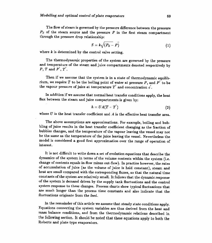
For simplicity we assume that all the components of a particular type (steam,or juice) in a particular evaporator stage have identical operating conditions sothat one can model each stage as a two compartment vessel shown schematicallyin figure 2, with a single heat exchange interface separating the steam and juicecompartments.
c concentration of dissolved solids in the in-flowing juice,,c concentration of solids in the out-flowing juice,F mass flow of juice into the juice side of the vessel,F' mass flow of juice from the juice side of the vessel,P pressure in the steam side of the vessel,p' pressure in the juice side of the vessel,Ps pressure of steam source,8 mass flow of steam into the steam side of the vessel,8' mass flow of vapour from the juice side of the vessel,T temperature of the steam side of the vessel,T' temperature of the juice (and steam) in the juice side of the vessel,TJ temperature of the juice entering the stage,Ts temperature of the steam entering the stage.
Steamside
Juiceside
5(Ps I T
•.. •..5) (
P,T pi I T'
•.. •..I
e) • (
5'P'/T')
F'T'/e/)
We note that by conservation of mass in steady state operation, the massflow of the condensate from the steam compartment must equal 8.
The flow of steam is governed by the pressure difference between the pressurePs of the steam source and the pressure P in the first steam compartmentthrough the pressure drop relationship:
S = kJ(Ps - P)
The thermodynamic properties of the system are governed by the pressureand temperature of the steam and juice compartments denoted respectively byP, T and p', T'.
Then if we assume that the system is in a state of thermodynamic equilib-rium, we require T to be the boiling point of water at pressure P, and P' to bethe vapour pressure of juice at temperature T' and concentration c'.
In addition if we assume that normal heat transfer conditions apply, the heatflux between the steam and juice compartments is given by:
h = UA(T - T')
The above assumptions are approximations. For example, boiling and bub-bling of juice results in the heat transfer coefficient changing as the fraction ofbubbles changes, and the temperature of the vapour leaving the vessel may notbe the same as the temperature of the juice leaving the vessel. Nevertheless themodel is considered a good first approximation over the range of operation ofinterest.
It is not difficult to write down a set of evolution equations that describe thedynamics of the system in terms of the volume contents within the system (i.e.change of contents equals in-flow minus out-flow). In practice however, the ratesof accumulation of juice (as the volume of juice is held constant), steam andheat are small compared with the corresponding fluxes, so that the natural timeconstants ofthe system are relatively small. It follows that the dynamic responseof the system is demand driven by the supply tank fluctuations and the controlsystem response to these changes. Process charts show typical fluctuations thatare much longer than the process time constants and also indicate that thefluctuations originate from the feed.
In the remainder of this article we assume that steady state conditions apply.Equations connecting the system variables are thus derived from the heat andmass balance conditions, and from the thermodynamic relations described inthe following section. It should be noted that these equations apply to both theRoberts and plate type evaporators.

the heat content (or more correctly enthalpy) of juiceat temperature T and concentration c,the heat content (enthalpy) of vapour (i.e. steam)at temperature T.
where S is defined in Section 2, and h, given by equation (2), is the heat fluxbetween the two compartments. For simplicity the heat loss in the steam com-partment is assumed to be included in the overall unit heat loss term includedin the next equation.
J(T], c)P - J(T', c')P' - V(T')S' = -h(l - u)
The mass balance requires that the mass flow of the juice into a vessel isequal to the sum of the juice and vapour out of the vessel:
As mentioned above there are thermodynamic (balance) relations betweenpressure, temperature, and concentration:
where Pv(T', c') denotes the vapour pressure of the juice at temperature T' andconcentration c'. A second relation derivable by inverting the above at c' = 0 is:

The equations in the previous section can be simplified somewhat by ex-panding V(Ts) in (3) around T:
dVV(Ts) ~ V(T) + (Ts - T) dT(T). (9)
Normally the last term in (9) is negligible compared with the latent heat definedby:
where L(T, c) is the latent heat of vapourisation of juice at temperature T andconcentration c. It follows from (3), (9) and (10) that:
Similarly, if we assume that the difference between the heat content of theincoming and out-flowing juice is small compared with the latent heat of vapor-isation then
L(T', c') ~ V(T') - J(T', c') (12)and the heat balance condition (4), using the mass balance condition (5), canbe approximated by:
h(1 - u) = {V(T') - J(T', c')}S' + {J(T', c') - J(T], c)}F ~ L(T', c')S'. (13)
An additional constant term can be calculated and added to this equation tocorrect for the approximations made here and in equation (11). The latent heatof the juice is included in the iteration given in the appendix in this manner.
Combining (11) and (13) we then obtain:
S' = {L(T,0)jL(T',c')}(1- u)S.
Again to a good first approximation the latent heat of condensation is equalto the latent heat of vaporisation, giving from (14):
S' ~ (1 - u)S.
It should be noted that in our simplification of the evaporator model theflow and concentration variables S, F, c and S', F', c' are simply related to oneanother through (5), (6) and (15) and thus do not depend on the thermodynamicvariables P, T and p', T' in this approximation.
As we show in the following section a set of evaporator vessels arrangedin series can be effectively modelled by repetitive application of the equationsderived by simplifying our basic model.

ITwe have a set of N evaporator vessels arranged in series (the normal config-uration) as shown in figure 3, with output flows Sm Fn and output concentrationCn from evaporator n providing input flows and concentration to evaporator n+1,equations (5), (6) and (15) can be used to derive the equation scheme for theset:
Sn+l = (1 - u)Sn, Fn+1 = Fn - Sn+l , Cn+l = Fncn/ Fnt1 (16)
for n = 0 to N, where So, Fa and Co denote the flows and concentration enteringthe first vessel. Equations (16) can be solved explicitly yielding:
This allows us to set the input conditions So, Fa, Co and use (17) to computethe discharge flows and concentrations for each vessel making up the set.
In practice there are product requirements, for example the final concentra-tion should be close to 0.7 . We discuss these conditions and other requirementsin the next section.
Since the final concentration is fixed by the product requirements and theinitial concentration is known (typically about 0.15) the last of equations (17)can be inverted to give:

as the required initial ratio of steam and juice flows in terms of CO/CN and theloss fraction u.
Another important end condition derives from the fact that the vapour outletat the end of the set is condensed while in contact with a reservoir maintained ata fixed temperature. In general from (2) and (11) we see that if Tn is defined to bethe temperature of the vapour leaving the vessel n, then to a first approximation:
for the latent heat (10), (20) can be solved for for Tn in terms of Tn+1 and Sn,yielding:
Tn = (aSn + UATn+d/(UA - bSn)
Sn = (1- utso.IT TN and U A are known, equation (22) can be evaluated backwards (i.e.
starting with the last stage n = N) to determine the initial temperature To andhence the initial steam pressure needed to drive the set. Note that TN is thefinal stage output temperature, and U A may vary from vessel to vessel in theset, particularly for a mixed set of Roberts and plate evaporators. Estimates ofthe temperature allow more accurate calculation of the heat transfers and thusthe calculation of more accurate flow, concentration and temperature values.This can be iterated as in the spreadsheet in the appendix to obtain an exactsolution of the equations.
Alternatively one can use the stepwise calculation backwards to derive arelation between To, So and TN which could be used in conjunction with (19) toset the required initial conditions.
In addition to the above considerations there are also fluid dynamic relationsderived from (1) and thermodynamic requirements from (7) and (8) that needto be checked for consistency with physical constraints as the flow proceeds fromone vessel to the next.
In a mixed set of Roberts and plate evaporators it is necessary to supply aconsistent ratio of juice and steam to the plate evaporators, or their operation
suffers considerably, possibly to the extent that no steam for the next stage isproduced. The Roberts evaporators are able to tolerate flow variations, and thenormal control is to maintain a constant level in the unit, which is done at theexpense of varying flows between the units. This however creates unsatisfactoryflow conditions for any plate evaporator stages.
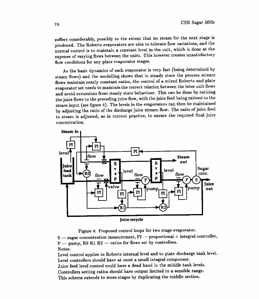
As the basic dynamics of each evaporator is very fast (being determined bysteam flows) and the modelling shows that in steady state the process streamflows maintain nearly constant ratios, the control of a mixed Roberts and plateevaporator set needs to maintain the correct relation between the inter unit flowsand avoid excursions from steady state behaviour. This can be done by ratioingthe juice flows to the preceding juice flow, with the juice feed being ratioed to thesteam input (see figure 4). The levels in the evaporators can then be maintainedby adjusting the ratio of the discharge juice stream flow. The ratio of juice feedto steam is adjusted, as in current practice, to ensure the required final juiceconcentration.
Steamout
Sugarcone.
Figure 4: Proposed control loops for two stage evaporator.S - sugar concentration measurement, PI - proportional + integral controller,P - pump, RO Rl R2 - ratios for flows set by controllers.Notes:Level control applies to Roberts internal level and to plate discharge tank leveLLevel controllers should have at most a small integral component.Juice feed level control could have a dead band in the middle tank levels.Controllers setting ratios should have output limited to a sensible range.This scheme extends to more stages by duplicating the middle section.

A recycle of juice from the final stage to the feed tank or the feed of anearlier stage is needed so that sugar concentrations below that needed are notproduced during start up, and possibly during major disturbances. Howeverthe aim should be to tune the control system so that it tolerates disturbanceswithout the production of out of specification product.
This proposed control scheme (given schematically in figure 4) places lessemphasis on maintaining precise level control in the Roberts evaporators. How-ever it is believed that more than adequate level control is possible as the feedforward adjustment of flows will result in less disturbance to the levels. As thelevel in the Roberts evaporators is set to an optimum value for efficient operation,minor excursions from the optimum will result in very little loss in efficiency.This very minor loss (if any) is the price necessary to obtain major gains in theoperation of the associated plate evaporators.
Two further improvements to the proposed control system are possible.Firstly instead of simply ratioing the flows a more complex scheduling of theflows based on model predictions could be used. It would first be necessary toadequately verify the model using plant data.
The second possible improvement relates to maintaining optimum conditionsin the plate evaporators (it is known that 30% level in the tubes provides nearoptimum performance in the Roberts evaporators and this can be set via thelevel set point). Conditions in the plate evaporators are set by the feed ratesof steam and juice and the plant configuration (namely the number of stages inthe plant and the number of plates used). The ratio of steam to juice is set bythe product requirements leaving only the feed rate as a possible adjustment.An experimental program is needed to determine the optimum conditions forthe plate evaporators (the equations developed indicate that the performanceshould be close to optimum over a wide range of conditions), then the plantconfiguration needs to be set so that the optimum performance is attained atthe required flow rate. Finally, the juice feed tank level control can be alteredso that levels over a region in the middle of the tank always give the flow ratecorresponding to optimum conditions. This has the effect of using part of the feedtank volume to smooth the feed flow, while still ensuring that, when necessary,the tank outflow is adjusted to match the incoming flow.
Physical or financial constraints may limit the full implementation of thiscontrol scheme. However in such cases, a reduced version may still give usefulbenefits. For instance, depending or the type of pump used, the inter stagepump power may be useable as an alternative to the flow meters.

A model of the evaporator set using mass, heat and thermodynamic balanceshas been developed. The major time constants are determined by the steam flowand are very short. Hence it is only necessary to consider steady state for theinitial control design.
A control scheme based on maintaining the juice flows in the appropriateratios is proposed. The ratios are adjusted to maintain levels and the requiredfinal sugar concentration. Possible extensions of the control scheme which willneed a more detailed knowledge of plant operation are proposed.
The project managers, Colin Thompson and Bill Whiten, would like to thankthe following delegates for their contributions: David Billinghurst, Paul Francis,Phil Howlett, John Perram, Reuben Thieberger, Rodney Weber, Jinhong Xiao,Debbie Zhang. David made several important contributions, particularly thebackward step-wise scheme (22), Phil assisted in the early foundations, Johnprovided valuable insights into the thermodynamic properties and overall struc-ture of the equations, Rodney provided a quick back of the envelope calculationwhich provided the essence of equations (17) and he developed from this an ini-tial version of the spreadsheet calculation. We the coordinators helped put itall together. Finally it is a pleasure to thank our CSR representative StephenVigh for the careful preparation and clear presentation of the problem and forthe patience and valuable inputs during our deliberations.
This spreadsheet calculates the flows, temperatures, and pressures in a fivestage evaporator. The steam input, fraction solids (sugar) in the feed juice andproduct juice, the final vacuum level, and the initial juice temperature are givenby the user. This then specifies all the remaining values. The specific heat ofthejuice has been included as this makes a small adjustment to the values, howeverthe specific heat of steam has not been included.
In some cases the initial steam temperature and pressure may become toohigh in which case the input steam flow needs to be reduced. Eight stages ofiteration are used to calculate the final values, however the initial iteration shownbelow can be seen to give a reasonable approximation to the final values in rows1 to 13.
Details of the spreadsheet numeric values and the formulas used (adaptedfrom Heat transfer performance in evaporators, Part I Theory and mechanisms,Sugar Research Institute, Mackay, Internal report No 191) follow.

~ __ A__ ~~I_-=-_~._L~~_1 i : Units : Input2 SteamBleecl······ ]tllh '3 Steam }Ilh4 Fr. Solids :Fr.------------------------_ .._---_ .._-------- .._--5 ~uice ..........:tph6 I
7 Li·---------··-·····----·-----····---··-TW/m2lC .--.------.--..-.-.. -~- ·--··----3000~ ----------20001 ----------2-0001 ----------2"OOOt--_·- 1500
8 J\r~~············~ ~?.::·::::::::·::::::~q9Qr ..:..::?99Q!.:::?9QQr: ...::?:qQQr:::::::j~QQ9 Efficiency............. .........i..l:l:~~]l:l:~?!.l:l:~?; ..l:l:~?L. 0.951011 ~~i~~j~:~:p:~i~t~i~::].g ~l:lj:::::~~:~~]..~~:~?l:·jQ:§~] '::j§:~~:] ·····73:2212 §t'3.e:tll1t.~.Il1P'3.r.e:ttlJr'3.].<::.....1..Ql:l:.1l:l1 ~l:l:~~.] ~~:.1!] l:l~:~9.] l:l~:~~L ~~:~~
:: ",.,."",; k~..............'0'98, ••••••••ge39:=~i 69.92r ~~'I•••.............'216 RatiC;--·················· ······--···0:951 0.95 :····j:~~] l:l:~~L::····0:95
17 Const:::':.::.::::: -:::::::.::::.:::::·::··:·::·§QQr::::·j:QQ1......l:l:l:ll:lj l:l:l:ll:lL.. 0.0018 Iteration 1 ,19 §:t~~~::::::·:···:Itph::::·~Q:QQ~:::jQ:~Q~·····~!:~!].~~:~l:l1 ~~:~Q:--::::~.1.:.1.~20 F'r.:§l:lli~!>.... . ...j F=r:.....l:l:1~] .. l:l:~9.1.....l:l:~~; l:l:~~] l:l:~?] l:l:!'l:l21 ~lJi<:'3... ....jtph.~~~:~~!.?~~:l:l~j ?Q.1:l:l~j .1~~:~~L 1.1.~:~~L. 71.8622 ~lJ.i.<:'3.J~Il1.!'.~r.e:t.tlJ.r.~j'<::... ..~9.: 1.l:ll:l:l:l?j.. ~~:l:l~L...~.1.:~~L l:l!:.1.?L 73.2223 .I?!~..........: (C).. l:l:~~!....l:l:~~]l:l:~~L 1.:!?L ~:~~.24 Dtbt :C 0.18; ....l:l:3!] 0.l:l4]. .:;q~L 23.8925 U*A*eflSi] 342000! 270l:l~1) 285148: 300156; 17772426 SteamternperaturejC 102.52] 100.64] 95.4~j~0:52L 84.41} 49.3327 Pressure :kPa 110.76] 103.67] 86:l:l3] 71.59) 56.~7] 1228 dHSt~arn()UVkg :kJ/kg 2459! 2460: 24~~) 24661 2470! 248529 dHJuice/kg:kJ/kg -4~L 21] 19] 18] 5930 New Ratio - 0.95: 0:~5j 0.95: 0.95] 0.9431 New Const -4.64: 1.731 1.191 0.82! 1.70
o E F G HOut 1 : Out 2 ] Out 3 ..i Out 4. Out 5
35.00: 0.00] 0.0l:l1 0'l:l0] 0.0090.00: ..46.88] ~5:8~L 4~:~~j .~~:l:ll:lL 42.22
........l:l:.1.?: l:l:~l:l] l:l:~~] l:l:~~l l:l:¥L..... 0.70
.. ~?!:!'~.: ...?~~:l:l~j ....1~~:~l:lL.155.44 : .1.1.~:~~; 70.22
C3 Input tph of steam entering the circuit.D3=D117 Calculated steam flows out of units after iteration.E3 to H3 Copy formula D3 across.
C4 Input feed juice fraction solids, Le. fraction dissolved sugar.D4=$C5*$C4/D5 Fraction solids in output, solids input to stage over juice
output.E4 to G4 Copy formula D4 across.H4 Input required final solids (Le. sugar) fraction.
C5= (D$2+ E$2+ F$2+ G$2+ H$2+ D3+ E3+ F3+G3+ H3)*H4/ (H4-C4)Juice feed from total steam produced and initial and fmal fractions solids.
D5=C5-D$2-D3 Juice tph from input juice tph minus steam produced in stage.

D7 to H7 Input heat transfer coefficient for each stage.D8 to H8 Input heat transfer surface for each stage.D9 to H9 Input efficiency fraction for each stage.
Cll Initial temperature of the juice.Dll=D120 Calculated juice temperature out of each stage after iteration.Ell to Hll Copy formula Dll across.
C12=C124 Calculated wet steam temperature out of each stage (& into followingstage).
D12 to G12 Copy formula C12 across.H12=EXP(-7.32362+2.363801 *LN(H13*1000)-
O.164849*LN(H13*1000)· 2+0.0042999*LN(H13*1000)· 3)Wet steam temperature calculated from final pressure.
C13=C125 Calculated pressure (output of stage and input to next stage) afteriteration.
D13 to G13 Copy formula C13 across.H13 Input final steam pressure.
D16=D9 Ratio of output steam to input steam (initial value).E16 to H16 Copy formula D16 across.
D17 to H17 Input initial estimates of constant term in linear formula for outputsteam from input steam tph (zero should be an adequate guess).
The following are the first stage of the iterative solution:C19=C$3 Tph of steam entering the circuit.D19=C19*D16+D17-D$2 Estimated steam (from linear approx.) going to next
stage.E19 to H19 Copy formula D19 across.
C20=C$4 Faction solids entering the circuit.D20 to G20 Copy formulas from D4 to G4.H20=H$4 Value of final fraction solids.
C21 to H21 Copy formulas from C5 to H5.
C22=C$1l Initial juice temperature.D22=D26+D24 Steam temperature plus increase in boiling temperature for
juice.E22 to H22 Copy formula D22 across.

D23=-0.1379+2.22*D20/(I-D20)+0.1188*(D20/(I-D20))'2 Value for use inD24.
E23 to H23 Copy formula D23 across.
D24=3D(D26+273r2/((373/D23r2+(100-D26)) Increase in juice boilingtemperature from steam temperature.
E24 to H24 Copy formula D24 across.
D25=D$7*D$8*D$9/CI9*3.6 Coefficient for use in C26.E25 to H25 Copy formula D25 across.
C26=0.3175+0.1559*D25-SQRT(0.02431 *D25' 2+0.09899*D25-777212-0.3118*D25*D22) Temperature of input steam from heat transfer solvedfor input temperature.
D26 to G26 Copy formula C26 across.H26 Copy formula H12.
C27=EXP( 18.23207-8.341154 *LN( C26)+ 1.90135 7*LN( C26)' 2-0.0882262*LN(C26r3)/1000 Pressure of wet steam from temperature.
D27 to G27 Copy formula C27 across.H27=H$13 Final output pressure.
C28=(2492600-2.0363*C26-3.2071 *C26*C26)/1000 Steam heat of vaporisationfrom temperature.
D28 to H28 Copy formula C28 across.
D29=3D( 4125.3-24.804 *C20+C22*( 0.067*C20+ 1.8691-0.009271 *C22 )+4125.3-24.804 *D20+D22*(0.067*D20+ 1.8691-0.009271 *D22) )*( C22-D22)/2000Heat loss by juice in the stage.
E29 to H29 Copy formula D29 across.
D30=D$9*C28/D28 Updated ratio of input steam to output steam.E30 to H30 Copy formula D30 across.
D31=D21 *D29/C28 Updated constant term for prediction of output steam.E31 to H31 Copy formula D31 across.
Copy formulas for line 18 to 31 seven times starting at line 32 (last line used is129).