modelling and analytical stability analysis of feedback ...modelling and analytical stability...
TRANSCRIPT

Modelling and Analytical Stability Analysis of Feedback Controlled Reactive Sputter
Processes
Joe Brindley, Benoit Daniel, Victor Bellido-Gonzalez, Dermot Monaghan
Gencoa Ltd, UK
1st May 2019www.gencoa.com
SVC TechCon 2019Long Beach, CA
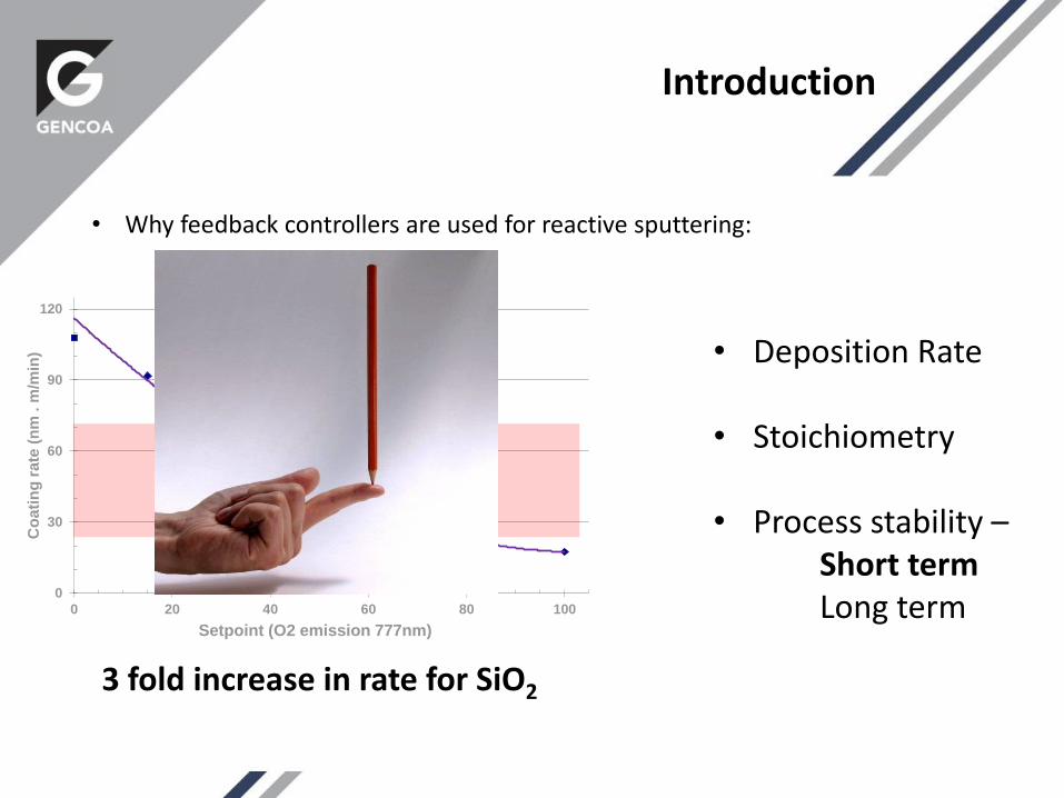
• Why feedback controllers are used for reactive sputtering:
Introduction
0
30
60
90
120
0 20 40 60 80 100
Co
ati
ng
ra
te (
nm
. m
/min
)
Setpoint (O2 emission 777nm)
Si and SiOx rates at 23 kW (dual rotatable)
• Deposition Rate
• Stoichiometry
• Process stability –Short termLong term
3 fold increase in rate for SiO2

How do we predict stability?
Nonlinear model
Linearization
Linear model
Predictions
Analysis – Eigen values
• Does not rely on simulation• Faster, more efficient• Deeper insight • Does not need interpretation – can be automated!
Approaches to evaluating stability
• Rule of thumb / best practice
• Simulation
• Analytic methods?
Modelling of the stability of reactive sputtering processes, Bartzch, Frach, Surface Coatings Technology, 2001Controllability Analysis of Reactive Magnetron Sputtering Process, Acta Physica Polonica A, 2012
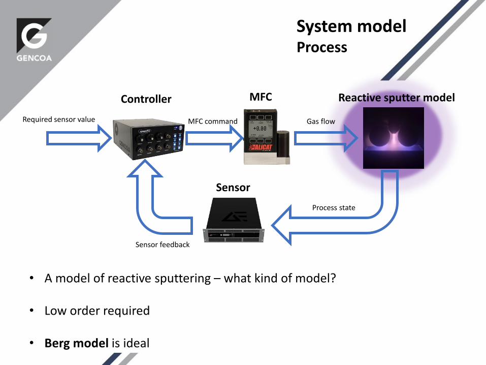
• A model of reactive sputtering – what kind of model?
• Low order required
• Berg model is ideal
System modelProcess
Controller MFC Reactive sputter model
Sensor
Required sensor value MFC command Gas flow
Process state
Sensor feedback
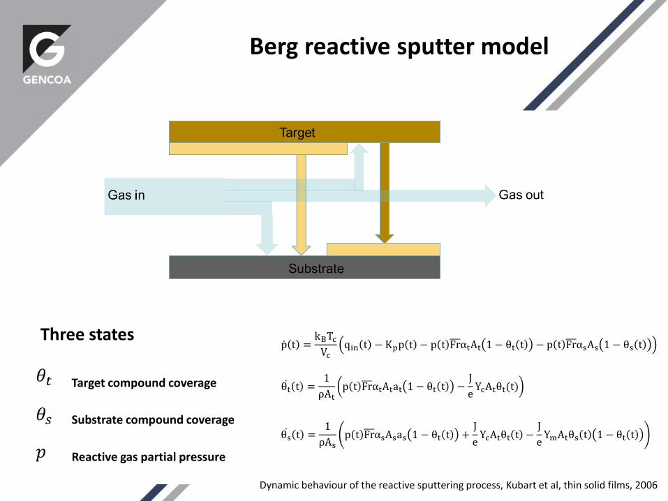
Berg reactive sputter model
𝜃𝑡
𝜃𝑠
𝑝
Three states
Target compound coverage
Substrate compound coverage
Reactive gas partial pressure
p t =kBTcVc
qin t − Kpp t − p t FrαtAt 1 − θt t − p t FrαsAs 1 − θs t
θt t =1
ρAtp t FrαtAtat 1 − θt t −
J
eYcAtθt(t)
θs t =1
ρAsp t FrαsAsas 1 − θt t +
J
eYcAtθt t −
J
eYmAtθs t 1 − θt t
Dynamic behaviour of the reactive sputtering process, Kubart et al, thin solid films, 2006
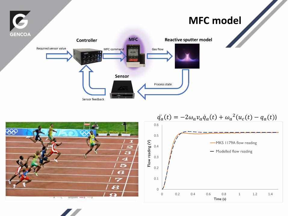
MFC model
𝑞𝑎 𝑡 = −2𝜔𝑎𝑣𝑎 𝑞𝑎 𝑡 + 𝜔𝑎2(𝑢𝑐(𝑡) − 𝑞𝑎(𝑡))
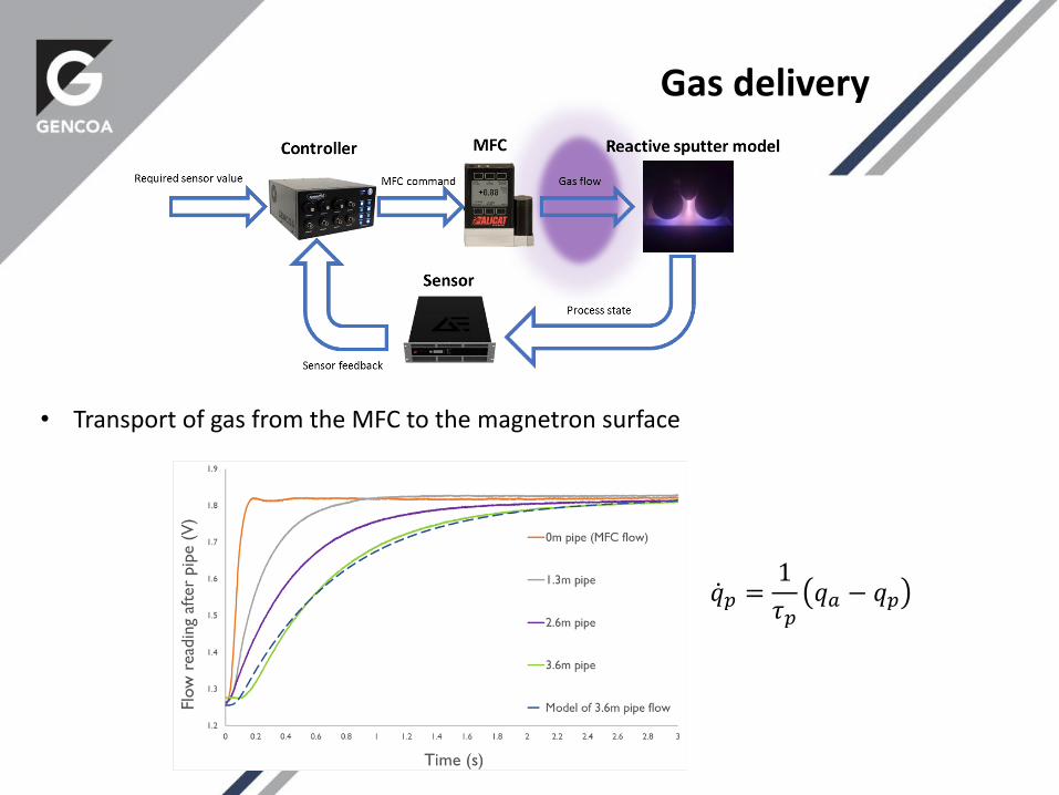
Gas delivery
• Transport of gas from the MFC to the magnetron surface
𝑞𝑝 =1
𝜏𝑝𝑞𝑎 − 𝑞𝑝

𝑉 =1
𝜏𝑠𝜃𝑡 − 𝑉
• Target voltage feedback
• Filtering is present in the power supply and controller
Target Voltage Sensor
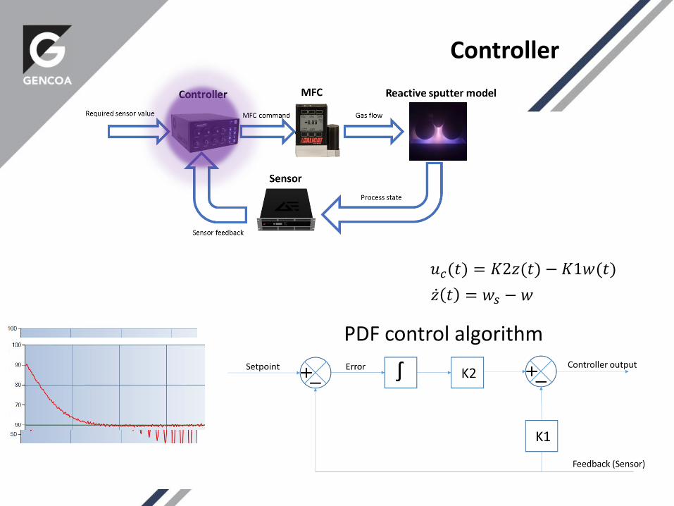
𝑢𝑐(𝑡) = 𝐾2𝑧(𝑡) − 𝐾1𝑤(𝑡)
𝑧 𝑡 = 𝑤𝑠 − 𝑤
PDF control algorithm
Controller
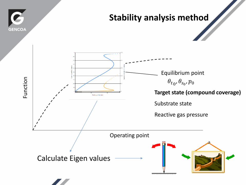
Fun
ctio
n
Operating point
Equilibrium point
𝜃𝑡0, 𝜃𝑠0 , 𝑝0
Stability analysis method
Target state (compound coverage)
Substrate state
Reactive gas pressure
Calculate Eigen values Stable?

𝑎 + 𝑗𝑏
A single number that represents stability of the whole system!
Stability analysis method
- Stable + Unstable
Eigen values
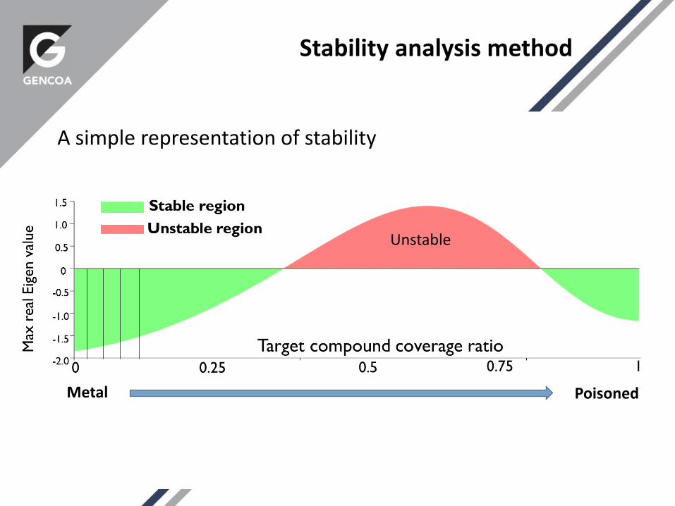
A simple representation of stability
Metal Poisoned
Unstable
Stability analysis method
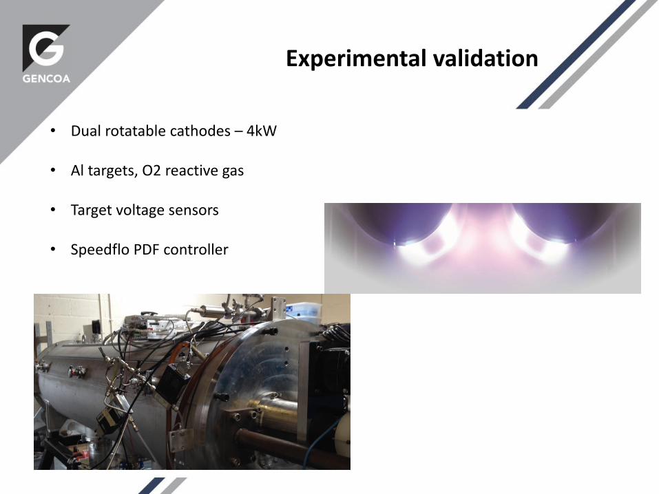
• Dual rotatable cathodes – 4kW
• Al targets, O2 reactive gas
• Target voltage sensors
• Speedflo PDF controller
Experimental validation
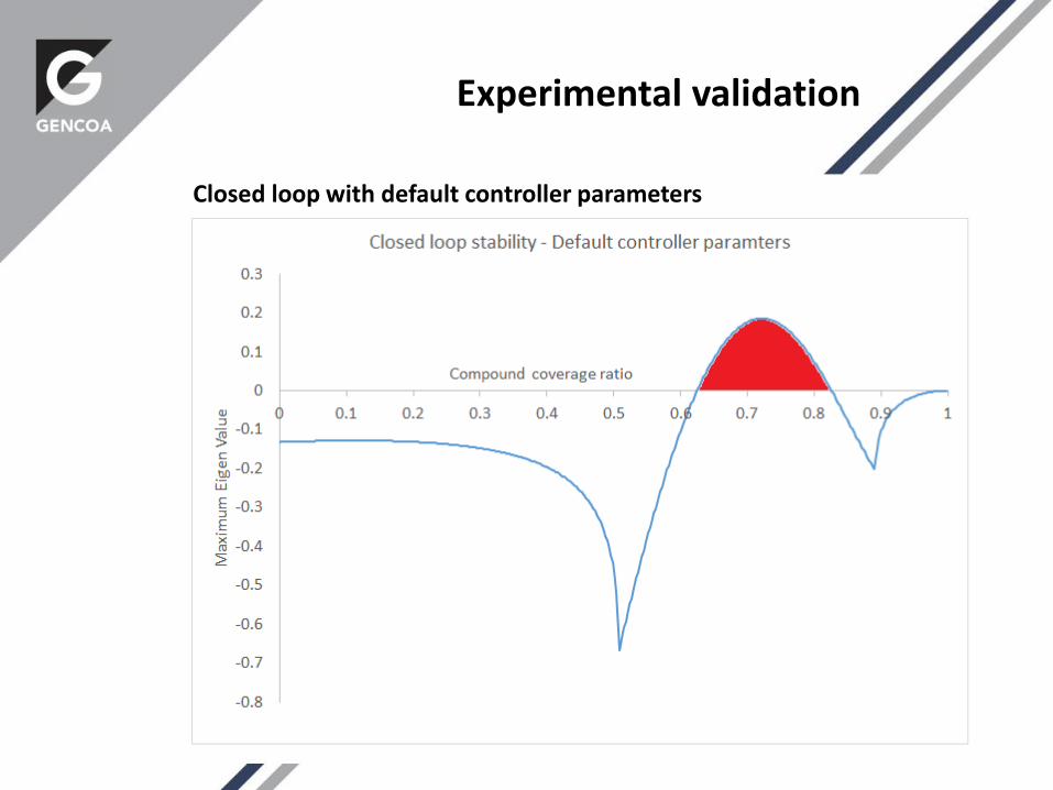
Closed loop with default controller parameters
Experimental validation

Experimental validation
Closed loop with default controller parameters
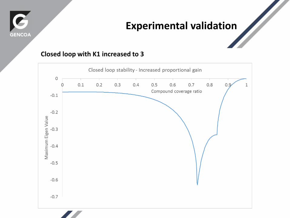
Closed loop with K1 increased to 3
Experimental validation
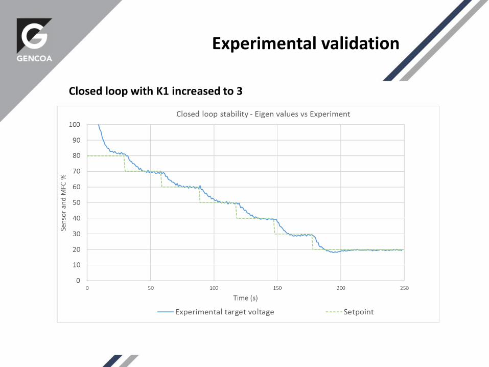
Experimental validation
Closed loop with K1 increased to 3
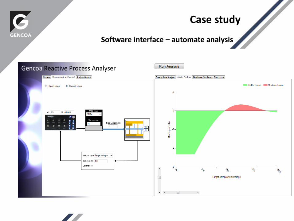
Case study
Software interface – automate analysis
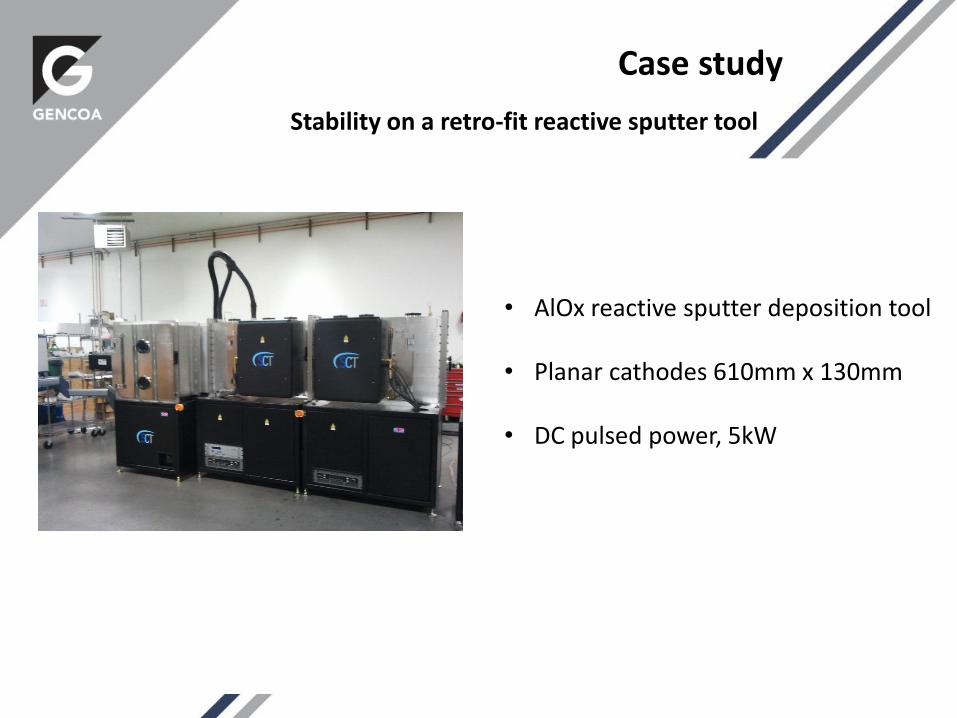
Case study
Stability on a retro-fit reactive sputter tool
• AlOx reactive sputter deposition tool
• Planar cathodes 610mm x 130mm
• DC pulsed power, 5kW
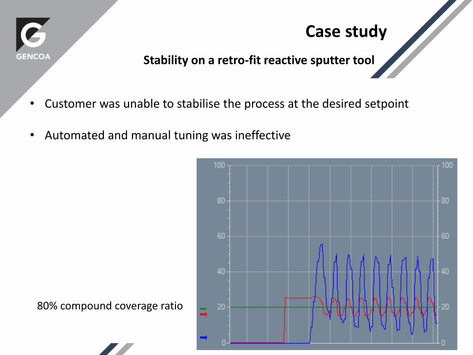
Case study
Stability on a retro-fit reactive sputter tool
• Customer was unable to stabilise the process at the desired setpoint
• Automated and manual tuning was ineffective
80% compound coverage ratio
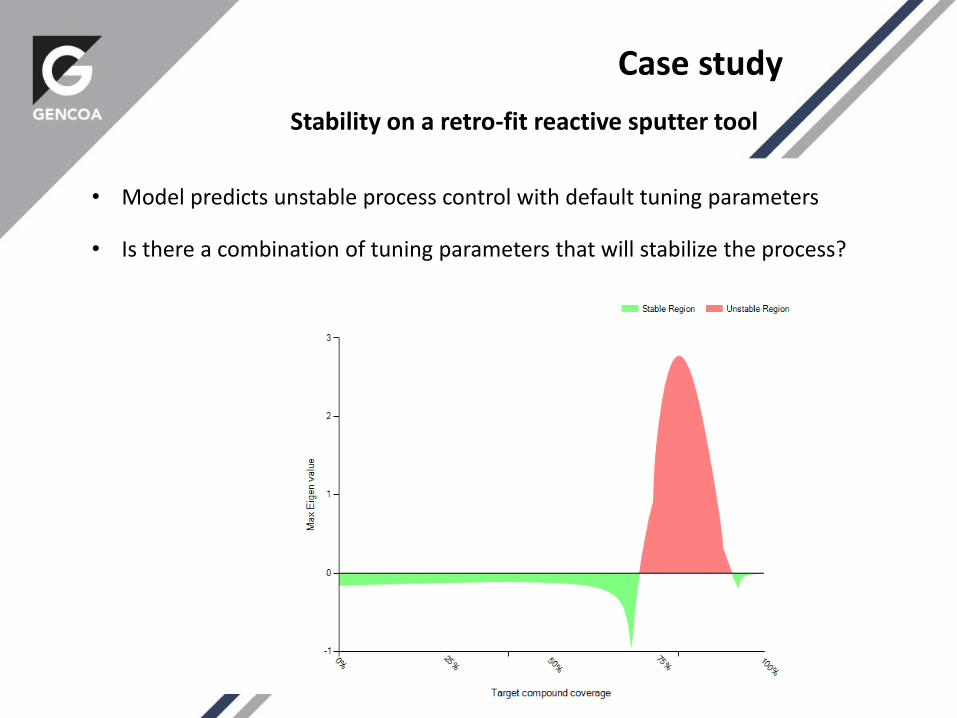
Case study
Stability on a retro-fit reactive sputter tool
• Model predicts unstable process control with default tuning parameters
• Is there a combination of tuning parameters that will stabilize the process?
Case study
Stability on a retro-fit reactive sputter tool
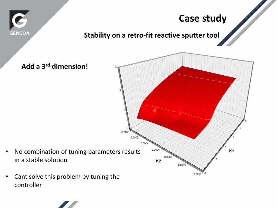
Add a 3rd dimension!
• No combination of tuning parameters results in a stable solution
• Cant solve this problem by tuning the controller
Case study
Stability on a retro-fit reactive sputter tool
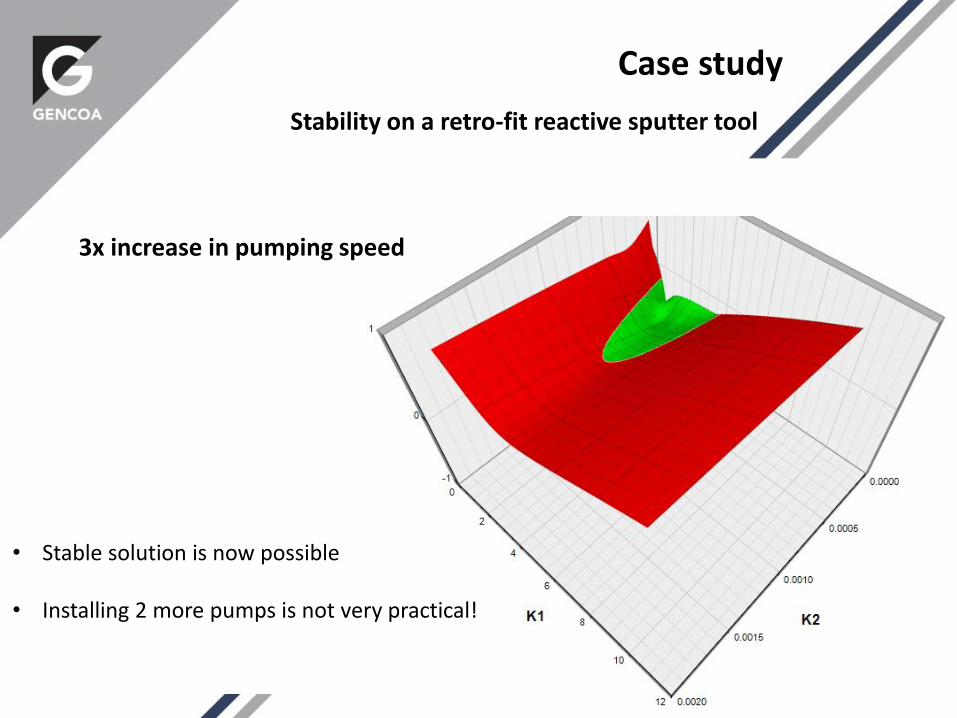
3x increase in pumping speed
• Stable solution is now possible
• Installing 2 more pumps is not very practical!
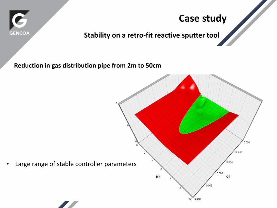
Reduction in gas distribution pipe from 2m to 50cm
Case study
Stability on a retro-fit reactive sputter tool
• Large range of stable controller parameters
Case study
Stability on a retro-fit reactive sputter tool
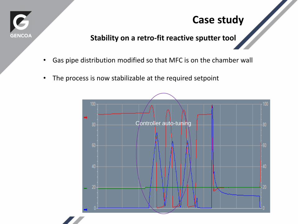
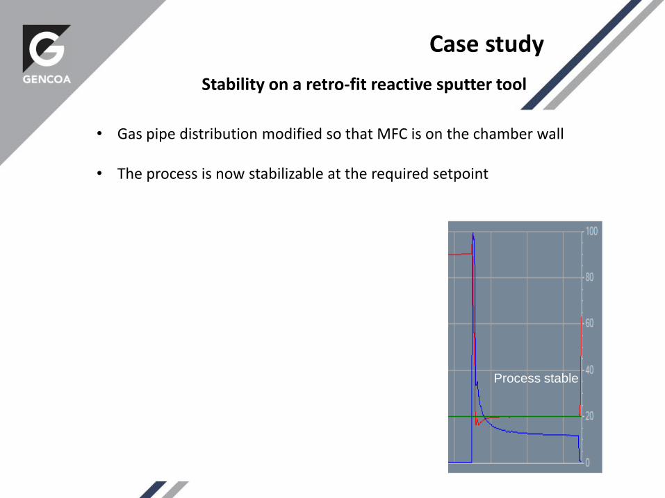
• Gas pipe distribution modified so that MFC is on the chamber wall
• The process is now stabilizable at the required setpoint
Controller auto-tuning
Case study
Stability on a retro-fit reactive sputter tool
• Gas pipe distribution modified so that MFC is on the chamber wall
• The process is now stabilizable at the required setpoint
Controller auto-tuning
Process stable
• A simple tool for investigating and predicting the stability of a reactive sputter process
• Can be used at the system design stage or for troubleshooting problems
• Does not replace experimental (or automated) tuning of the controller
Future possibilities:
• Latest models
• Co-sputtering, dual reactive gases
• Multiple process zones and gas injection points – stability of interactions
• Software environment
Summary
Conclusions
Journal of Physics D: Applied Physics
A time-dependent model for reactive sputter
deposition
K Strijckmans and D Depla
Published 8 May 2014
Thank you for your attention!
Please visit us at Booth 720