modelling and analysis of facts devices for stability...
TRANSCRIPT

MODELLING AND ANALYSIS OF FACTS DEVICES FOR
STABILITY IMPROVEMENT IN POWER SYSTEM USING MATLAB SOFTWARE
MOHAMED SALEH ALI NASER
A thesis submitted in
fulfilment of the requirement for the award of the
Degree of Master of Electrical Engineering
Faculty of Electrical and Electronic Engineering
Universiti Tun Hussein Onn Malaysia
November 2017

iii
Dedicated with gratitude to my country Libya for the huge support and giving me this
opportunity to study overseas.

iv
ACKNOWLEDGEMENT
First and foremost, my praise to Almighty Allah for giving me the power and persistence
to complete this study and peace be upon his final Prophet and Messenger Mohammed,
SAW.
I would like to express my sincere appreciation to my supervisor, Dr. Siti Amely
Binti Jumaat for the guidance and constant given support throughout the duration for this
research.
I have to thank my dearly loved parents for their love and support throughout my
life. Thank you both for giving me strength to reach for the stars and chase my dreams.
My Brothers deserve my wholehearted thanks as well.
Last but not least, my great thankful to all my friends who stood beside me and
pushed me forward to complete my studies.

v
ABSTRACT
The concept of FACTS (Flexible Alternating Current Transmission System) refers to a
family of power electronics-based devices able to enhance AC system controllability and
stability and to increase power transfer capability. FACTS devices, thanks to their speed
and flexibility, are able to provide the transmission system with several advantages such
as: transmission capacity enhancement, power flow control, transient stability
improvement, power oscillation damping and voltage stability. This project investigates
modelling and analysis of static Var Compensator (SVC), Static Synchronous
Compensator (STATCOM) and Unified Power Flow Controller (UPFC) performance for
stability improvement in power system. The ability of these FACTS devices for power
flow control at normal condition are examined. In addition, the capability for damping
electromechanical oscillations at fault condition in a power system are studied by these
devices. This is achieved by modelling three phase test system 220KV in long
transmission line. Furthermore, the UPFC device has tested in Kundur’s Four-Machine
Test System at fault condition. The MATLAB/Simulink software is used to compare
between different FACTS devices performance. The performance of SVC, STATCOM
and UPFC is compared from each other. In comparative result UPFC is given the better
result than the others. The simulation results in both of the test systems demonstrate the
effectiveness and robustness of the proposed SVC, STATCOM and UPFC on stability
improvement of the power system.

vi
CONTENTS
TITLE i
DECLARATION ii
DEDICATION iii
ACKNOWLEDGMENT iv
ABSTRACT v
CONTENTS vi
LIST OF TABLES ix
LIST OF FIGURES x
LIST OF APPENDICES xiv
CHAPTER 1 INTRODUCTION 1
1.1 Background 1
1.2 Problem statement 2
1.3 Objectives of project 3
1.4 Scope of project 3
1.5 Outline of thesis 4
CHAPTER 2 LITERATURE REVIEW 5
2.1 Introduction 5
2.2 Previous research 5
2.3 Power system stability 9
2.4 The FACTS devices 14
2.4.1 Series controllers 14
2.4.1.1 Thyristor controlled series compensator (TCSC) 15
2.4.1.2 Static synchronous series compensator (SSSC) 16
2.4.2 Shunt controllers 17
2.4.2.1 Static VAR compensator (SVC) 17
2.4.2.1.a SVC structure 18
2.4.2.1.b SVC operating principle 19
2.4.2.1.c Characteristics of SVC 20

vii
2.4.2.1.d SVC control system 22
2.4.2.2 Static synchronous compensator (STATCOM) 22
2.4.2.2.a STATCOM structure 24
2.4.2.2.b STATCOM operating principle 24
2.4.2.2.c Characteristics of STATCOM 26
2.4.2.2.d STATCOM control system 26
2.4.3 Combined series-series controllers 28
2.4.3.1 Inter line power flow controller (IPFC) 28
2.4.4 Combined series-shunt controllers 29
2.4.4.1 Unified power flow controller (UPFC) 30
2.4.4.1.a UPFC structure 30
2.4.4.1.b Operating principle and characteristics of UPFC 31
2.4.4.1.c UPFC control system 34
CHAPTER 3 METHODOLOGY 37
3.1 Introduction 37
3.2 Project flowchart 38
3.3 Project block diagram 39
3.4 Test system description 40
3.5 Modelling of the first test system by
MATLAB/Simulink software
41
3.6 Modelling of the Kundur's Test System by
MATLAB/Simulink software
49
CHAPTER 4 SIMULATION RESULTS AND DISCUSSION 51
4.1 Introduction 51
4.2 Simulation results 51
4.3 The test system at normal condition 52
4.3.1 The test system at normal condition without
FACTS
52
4.3.2 The test system at normal condition with FACTS 54
4.3.2.1 The test system at normal condition with SVC 54
4.3.2.2 The test system at normal condition with
STATCOM
56
4.3.2.3 The test system at normal condition with UPFC 58
4.3.3 Comparison of results between SVC, STATCOM
& UPFC at normal condition
60
4.4 The test system at fault condition 60

viii
4.4.1 The test system at fault condition without FACTS 61
4.4.2 The test system at fault condition with FACTS 63
4.4.2.1 The test system at fault condition with SVC
63
4.4.2.2 The test system at fault condition with
STATCOM
65
4.4.2.3 The test system at fault condition with UPFC 67
4.4.3 Comparison of results between SVC, STATCOM
and UPFC at fault condition
69
4.5 Kundur's Four-Machine Test System 71
4.5.1 Kundur’s Four-Machine Test System at normal
condition without FACTS
72
4.5.2 Kundur’s Four-Machine Test System at fault
condition without FACTS
74
4.5.3 Kundur’s Four-Machine Test System at fault
condition with UPFC
77
4.5.4 Comparison of results at fault condition with and
without UPFC
80
CHAPTER 5 CONCLUSION 82
5.1 Conclusion 82
5.2 Recommendation for future work 83
REFERENCES 84
APPENDIX A 88
APPENDIX B 90
APPENDIX C 92
APPENDIX D 94
APPENDIX E 96
APPENDIX F 100
APPENDIX G 104
APPENDIX H 110
APPENDIX I 112

ix
LIST OF TABLES
2.1 Operating principle for STATCOM 25
4.1 Compare results between SVC, STATCOM & UPFC at
normal condition
60
4.2 Compare results between SVC, STATCOM & UPFC at fault
condition
69
4.3 Compare results at fault condition with and without UPFC 81

x
LIST OF FIGURES
2.1 Example of a two ended power system 10
2.2 Active and reactive power flow and active reactive current
flow vector representation
11
2.3 Voltage and current phasors 13
2.4 Power angle curves for different values of X 13
2.5 One-line diagram of a series FACTS controller 15
2.6 Circuit diagram of thyristor controlled series compensator
(TCSC)
15
2.7 Block diagram of static synchronous series compensator
(SSSC)
16
2.8 One-line diagram of a shunt FACTS controller 17
2.9 Circuit diagram of static Var compensator (SVC) 19
2.10 Schematic diagram of a TSC-TCR 20
2.11 V-I Characteristics of SVC 21
2.12 The control system of SVC 22
2.13 Static synchronous compensator 23
2.14 Configuration of STATCOM 24
2.15 V-I Characteristics of STATCOM 26
2.16 Control system block diagram of STATCOM 27
2.17 One-line diagram of a series-series FACTS controller 28
2.18 Schematic diagram of IPFC 29
2.19 One-line diagram of a series-shunt FACTS controller 29
2.20 Typical configuration of UPFC 30
2.21 UPFC structure 31
2.22 UPFC model without real power exchange between its two
converters
32

xi
2.23 Phasor diagram when UPFC working in different modes 33
2.24 Voltage constraints of UPFC series device 34
2.25 Typical UPFC control system hierarchy 36
3.1 Flowchart of the project 38
3.2 The block diagram of the project process 39
3.3 Single line diagram for the test system 40
3.4 Single line diagram for Kundur's Four-Machine Test System 41
3.5 The SimPowerSystems main library 42
3.6 Interconnection of the Machine M1 and the Transformer Tr1
models
42
3.7 The Simulink library browser 43
3.8 The dialog box of the Bus Selector block 44
3.9 Block diagram of the Machine M1 regulator 44
3.10 The Machine M1 regulator box 44
3.11 Interconnecting the Reg_M1 box to the Machine M1 model 45
3.12 Model of bus bars B1 45
3.13 The dialog box of the bus bar B1 46
3.14 Interconnection of substation I and B1 boxes 46
3.15 The model of transmission line L1-3 47
3.16 The dialog box of a circuit of the transmission line L1-3 47
3.17 The model of three phase parallel load 48
3.18 The dialog box of the three-phase load connected at B3 and
B2
48
3.19 Structure of the first test system
48
3.20 Kundur's Four-Machine Test System area 1
49
3.21 Kundur's Four-Machine Test System area 2
50
3.22 Structure of Kundur’s Four-Machine Test System
50
4.1 The test system at normal condition without FACTS 52
4.2 Voltage on B1, B2 and B3 at normal condition without
FACTS
53

xii
4.3 Active power on B1, B2 and B3 at normal condition without
FACTS
53
4.4 The test system at normal condition with SVC 54
4.5 Voltage on B1, B2 and B3 at normal condition with SVC 55
4.6 Active power on B1, B2 and B3 at normal condition with
SVC
55
4.7 The test system at normal condition with STATCOM 56
4.8 Voltage on B1, B2 and B3 at normal condition with
STATCOM
57
4.9 Active power on B1, B2 and B3 at normal condition with
STATCOM
57
4.10 The test system at normal condition with UPFC 58
4.11 Voltage on B1, B2 and B3 at normal condition with UPFC 59
4.12 Active power on B1, B2 and B3 at normal condition with
UPFC
59
4.13 The test system at fault condition without FACTS 61
4.14 Voltage on B1, B2 and B3 at fault condition without FACTS 62
4.15 Active power on B1, B2 and B3 at fault condition without
FACTS
62
4.16 The test system at fault condition with SVC 63
4.17 Voltage on B1, B2 and B3 at fault condition with SVC 64
4.18 Active power on B1, B2 and B3 at fault condition with SVC 64
4.19 The test system at fault condition with STATCOM 65
4.20 Voltage on B1, B2 and B3 at fault condition with
STATCOM
66
4.21 Active power on B1, B2 and B3 at fault condition with
STATCOM
66
4.22 The test system at fault condition with UPFC 67
4.23 Voltage on B1, B2 and B3 at fault condition with UPFC 68
4.24 Active power on B1, B2 and B3 at fault condition with
UPFC
68
4.25 Voltage on B1 for SVC, STATCOM and UPFC at fault
condition
70
4.26 Voltage on B2 for SVC, STATCOM and UPFC at fault
condition
70

xiii
4.27 Voltage on B3 for SVC, STATCOM and UPFC at fault
condition
71
4.28 Kundur's Four-Machine Test System at normal condition
without FACTS
72
4.29 Voltage on B5, B6, B7, B8, B9, B10 and B11 at normal
condition without FACTS
73
4.30 Active power on B5, B6, B7, B8, B9, B10 and B11 at
normal condition without FACTS
73
4.31 Load angle M1, M2, M3 and M4 at normal condition
without FACTS
74
432 Rotor speed M1, M2, M3 and M4 at normal condition
without FACTS
74
4.33 Kundur's Four-Machine Test System at fault condition
without FACTS
75
4.34 Voltage on B5, B6, B7, B8, B9, B10 and B11 at fault
condition without FACTS
75
4.35 Active power on B5, B6, B7, B8, B9, B10 and B11 at fault
condition without FACTS
76
4.36 Load angle M1, M2, M3 and M4 at fault condition without
FACTS
76
4.37 Rotor speed M1, M2, M3 and M4 at fault condition without
FACTS
77
4.38 Kundur's Four-Machine Test System at fault condition with
UPFC
78
4.39 Voltage on B5, B6, B7, B8, B9, B10 and B11 at fault
condition with UPFC
78
4.40 Active power on B5, B6, B7, B8, B9, B10 and B11 at fault
condition with UPFC
79
4.41 Load angle M1, M2, M3 and M4 at fault condition with
UPFC
79
4.42 Rotor speed M1, M2, M3 and M4 at fault condition with
UPFC
80

xiv
LIST OF APPENDICES
APPENDIX TITLE PAGE
A The three phase synchronous generator M1 & M2 data 88
B The three phase transformer Tr1 and Tr2 data 90
C Transmission line L1-3, L1-2 and L2-3 data 92
D Three phase load connected at bus B3 and B2 data 94
E The three phase synchronous generator M1 , M2 , M3
and M4 data Kundur’s system
96
F The three phase transformer Tr1 , Tr2 , Tr3 and Tr4
data Kundur’s system
100
G Transmission line L5-6, L6-7, L7-8, L8-9, L9-10 and
L10-11 data Kundur’s system
104
H Three phase load connected at bus B7 and B9 data
Kundur’s system
110
I The parameter for FACTS devices 112

CHAPTER 1
INTRODUCTION
1.1 Background
The modern electric power system is facing many challenges due to the increased
complexity of their operation and structure. An electric power system is a complex
network comprising of numerous generators, transmission lines, a variety of loads and
transformers. As a consequence of increasing power demand, some transmission lines are
more loaded than was planned when they were built [1]. With the increased loading of
long transmission lines, the problem of transient stability after a major fault can become a
transmission limiting factor. Now power engineers are much more concerned about
transient stability problem due to blackout in northeast United States, Scandinavia,
England and many countries as well [2]. Transient stability refers to the capability of a
system to maintain synchronous operation in the event of large disturbances such as multi-
phase short-circuits faults or switching of lines When subjected to a transient disturbance,
the stability of the system depends on the nature of the disturbance as well as the initial
operating condition. The system must be able to operate satisfactorily under these
conditions and successfully meet the load demand. It must also be able to survive
numerous disturbances of a severe nature, such as a short-circuit on a transmission line or
loss of a large generator [3]. Recently, the great evolution of power electronics has given
privilege to FACTS devices (Flexibles AC Transmission Systems) in terms of rapidity,
efficiency and flexibility to better exploit power system and improve its dynamic behavior
[4].

2
FACTS controllers are capable of controlling the system condition in a very fast
manner and this feature of FACTS can be exploited to improve the voltage stability and
steady-state and transient stabilities of a complex power system. This allows increased
utilization of existing system closer to its thermal loading capacity and thus avoiding the
need to construct new transmission lines [1].
Static Var Compensator (SVC), Static Synchronous Compensator (STATCOM)
and Unified Power Flow Controller (UPFC) are members of FACTS family which use
power electronics to control power flow and voltage regulation on the power system. They
are also capable of enhancing the transient stability by increasing or decreasing the power
transfer capability when the machine angle increases or decreases.
1.2 Problem statement
Turbulences and faults in power systems pose adverse challenges. They include power
swings, oscillations, loss of synchronism and outages. This circumstance causes power
system problems of instability and even collapse. Voltage collapse results when active and
reactive power balance equations fail or the inability of load dynamics attempt to restore
power consumption beyond the capability of the transmission system and the connected
generation to provide the required reactive support. Large disturbances such as a three-
phase fault decelerate loads and cause instability to generating units. Further still,
continuous demand in electric power system network as well as heavy loading leading to
system instability and straining of the thermal limits.
Traditionally, fixed or mechanically switched shunt and series capacitors, reactors
and synchronous generators were being used to solve much of the problem. However,
there are restrictions as to the use of these conventional devices. The desired performance
was not being able to achieve effectively. Wear and tear in the mechanical components
and the slow response was the heart of the problems. There was a greater need for the
alternative technology made of solid-state devices with fast response characteristics.

3
1.3 Objectives of project
The goals of this project are as follow:
i. To model power system long transmission line 220KV and 230KV test systems.
ii. To simulate and analyze power system long transmission line without FACTS
devices in normal condition and fault condition.
iii. To simulate and analyze power system long transmission line with FACTS devices
such as static Var Compensator (SVC), Static Synchronous Compensator
(STATCOM) and Unified Power Flow Controller (UPFC) in normal condition and
fault condition.
iv. To compare between SVC, STATCOM and UPFC for the improvement of
transient stability of the power system.
1.4 Scope of project
This project is executed in accordance with the followings:
i. The first test power system contains two power stations with two transformers and
three bus bars. These bus bars are connected to long transmission lines with loads,
where the system operates under 220KV, frequency 50HZ, and 100KVA base.
ii. The second test power system is Kundur's Four-Machine Test System. It is
consisting of two fully symmetrical areas linked by two lines of 220 km length.
This test system operates under 230KV, frequency 60HZ, and 100KVA base.
iii. The simulation of this power system is carried out by using MATLAB/Simulink
software under Windows operating systems.
iv. The FACTS devices are connected to the test system in shunt as in SVC and
STATCOM, or in combined series-shunt as in UPFC.

4
1.5 Outline of thesis
This section outlines the structure of the thesis and summarizes each of the chapters. The
first chapter of introduction explains the problem statements, goals, the scope of the study
and the structure of this master project. Next is chapter two which is the chapter on
literature review. The second chapter discusses previous research and Power system
stability. Also, describes all type of FACTS devices such as Series controllers, Shunt
controllers, Combined series-series controllers and Combined series-shunt controllers. The
characteristic and principle operation of each type are described as well. Meanwhile, the
research methodology is described in chapter three. This chapter explains clearly how to
model the test system using MATLAB/Simulink software. Moving to chapter four which
analyze and compare the results of using FACTS devices in the network. Finally, a
conclusion for the whole project based on the finding of the results is conducted in chapter
five as well as some recommendations for future work.

CHAPTER 2
LITERATURE REVIEW
2.1 Introduction
This chapter sets the scene by systematically reviewing the FACTS devices in existence,
paving the way for the study of the effects of a particular type of FACTS-based device on
power system stability.
This chapter is divided into three main parts. The first part is a literature survey to
understand the different types of FACTS devices and the concepts of series and shunt
types of FACTS devices. The second part is the concept of power system stability and to
know which parameters must be changed to increase the power flow through a
transmission system. The last third part presents the different types of FACTS devices,
which are conventional thyristor based FACTS devices and the voltage source convertor
based FACTS devices.
2.2 Previous research
Wang & Swift (1997) published a paper in which three FACTS devices such as Static Var
compensator (SVC), Controllable Series compensator (CSC) and Phase Shifter (PS) are
used. Phillips-Heffron model is used in this paper. This paper relies on theoretical analysis
of a general single machine infinite bus power system. On basis of this model, the

6
effectiveness of FACTS damping controllers has been investigated by analyzing there
damping torque contribution to the power system. Analytical conclusions about the
FACTS damping controllers and their robustness to variation of system operating
conditions are also obtained which are shown by the results of numerical calculations and
non-linear simulations of an example power system presented in this paper [5].
An example of applications of UPFC for optimal flow of power and reduction of
losses is demonstrated by Noroozian, Angquist, Ghandhari & Andersson (1997). Both the
objectives are achieved simultaneously by using proper control parameters. The
performance of UPFC is compared with phase shifting transformer (PST). It is obtained
that the impact of PST in minimizing losses and optimal power flow is less as compared to
UPFC. An algorithm is proposed to determine the optimum size of UPFC [6].
Wang, Hur, Chung, Watson, Arrillaga & Matair (2000) have designed an optimal
PI controller for the enhancement of transient stability of a single machine infinite bus
power system with SVC using genetic algorithm approach. The application of this
controller is concerned with the damping of oscillations of a synchronous generator as
well as to control the system voltage [7].
Keshavan & Prabhu (2001) demonstrated the damping of torsional oscillations in
which STATCOM is connected at the middle of transmission line. For analysis, the IEEE
second benchmark model system-l is considered in this paper. It is demonstrated that, the
system is effectively damped under SSR conditions. In this paper, Eigen value technique
is used for analysis. Thus, it demonstrated that when STATCOM is used for damping SSR
and controlled by voltage controller and CIV signal, all the unstable torsional modes are
stabilized with good stability margins. STATCOM used to damp the subsynchronous
oscillations in addition to enhancing the power limits by providing voltage support [8].
Lu & Abur (2001) presented an improving system security via optimal placement
of thyristor controlled series capacitor. Single contingency sensitivity method has been
implemented for branch flows. This can be used to improve a branch prioritizing index in
order to rank branches for optimal placing of TCSCs [9].
Farsangi, Song & Lee (2004) have proposed methods to select the input signals for
both single and multiple FACTS devices in small and large power systems. Different input
– output controllability analyses have been used to assess the most appropriate input
signals for the SVC, SSSC and UPFC for achieving good damping of the interarea
oscillations [10].
Haque (2004) has proposed a control strategy for the shunt FACTS devices to
improve the first swing stability limit of a simple power system. It is shown that the speed
based bang-bang control is unable to use the entire decelerating area in maintaining

7
stability. The proposed control strategy improves the stability limit first by maximizing the
decelerating area and then fully utilizing it in counter balancing the accelerating area [11].
A study by Hossam-Eldin, Elrefaie & Mohamed (2006) shows how UPFC affects
the transmission system having series voltage and shunt current injection. UPFC provides
better results than other devices and its advantages are also discussed. Various features of
UPFC are discussed and some of them include improvement of the system characteristics,
power factor, control of voltage and power flow thus providing the best transient and
dynamic stability. Simulation is done for various loads and system voltages [12].
According to Nikoukar & Jazaeri (2007), the introduction of flexible AC
transmission system (FACTS) in a power system improves the stability, reduces the
losses, reduces the cost of generation and also improves the loadability of the system. In
the proposed work, a non-traditional optimization technique, genetic algorithm is used to
optimize the varios process parameters involved of FACTS devices in a power system.
The various parameters taken into consideration were the location of the device, their type
and their rated values of the devices. The simulation was performed on a 30-bus modified
IEEE power system with various types of FACTS controllers, modeled for steady state
studies. The optimization results clearly indicate that introduction of FACTS devices in a
right location increases the loadability of the system and genetic algorithm can be
effectively used for this kind of optimization [13]
Shaheen, Rashed & Cheng (2008) proposed a new control scheme for STATCOM
which is based on Nonlinear Predictive Control System using Optimal Control Approach
for enhancing power system stability and voltage regulation. This proposed control
scheme is applied to the mathematical model of STATCOM. Simulations are done on
single-machine infinite bus power system equipped with STATCOM using
PSCAD/EMTDC software package under steady-state and dynamic stability conditions.
Simulation result shows that robustness and superiority of proposed controller compared
to the conventional PI controllers. However, for nonlinear system on-line optimization
numerical computation burden is very large and the demand may not be satisfied for real
time control. To overcome this drawback a new Nonlinear Predictive Control System
using optimal control approach to control STATCOM under the static and dynamic
operation conditions of power system has been used in this paper [14].
Sankar, Balaji & Arul (2010) published a paper in which simulation work is done
in PSPICE. FACTS devices used are TCR (thyristor controlled reactor), TCVR (thyristor
controlled voltage regulator) and UPFC (unified power flow controller). In this paper
control strategy for real and reactive power of transmission line using FC-TCR and the
voltage regulation using TCVR and UPFC is described. In case of FC-TCR , the control is

8
achieved by controlling the current through TC reactor by varying the phase of thyristor
switch. In TCVR system, power flow in line is controlled by voltage regulation method.
UPFC boost the transmission line and thus increases the power flow in the line [15].
Murali, Rajaram & Reka (2010) issued a paper in which significant area of
research is improvement of transient stability. FACTS devices used in this paper are SVC
(Static Var Compensator), SSSC (Static Synchronous Series Compensator) and TCSC
(Thyristor Controlled Series Compensator). Simulations are carried out in
Matlab/Simulink environment for the two-area power system model with UPFC to analyze
the effects of UPFC on transient stability performance of the system This paper
investigates improvement of transient stability of two-area system by using UPFC which
is capable of controlling the real and reactive power flows in a transmission line. It is
considered that a 3-phase symmetrical short-circuit fault of 300 milli-seconds duration
occurs at bus-3. After that performance of UPFC is compared with other FACTS devices
such as Static synchronous series compensator (SSSC), Thyristor controlled series
compensator (TCSC), and Static Var Compensator (SVC) respectively. Simulation results
shows the effectiveness and robustness of UPFC on transient stability improvement of the
system [16].
In a study by Ciausiu & Eremia (2011), the problem of identifying stability
reserves and finding out best solutions to improve available security margins in order to be
at safe distance from a blackout is analyzed. Computation of the stability limits for power
system either with or without FACTS devices are done in order to highlight the gain in
power system stability and control by using these devices. Methodology to choose
between different locations for FACTS device in order to increase the security margins of
analyzed power system is proposed. Technical aspect treated in paper consist in assessing
the stability reserves for power system for specific constrained area in power system,
beyond which black out might appear [17].
Singh, Phunchok & Sood (2012) promulgated a paper in which FACTS devices
used are SVC and TCSC. IEEE-5 bus system has been used for running the load flow
using power system tool box (PSAT). Simulation of IEEE-5 bus system with and without
FACTS devices (SVC and TCSC) is done on PSAT. In this paper NR method for load
flow is used, because of its reliability towards convergence and not sensitive nature to
starting solution. In large scale power flow studies, NR is more successful because of its
strong convergence characteristics. SVC helps to improve the voltage profile of the system
and TCSC helps to increase the power flow in the transmission line and also reduces the
overloading and unreliability of the transmission system [18].

9
Vijayan & Padma (2013) demonstrated the need of proper location of FACTS
devices in the power system to maintain bus voltage and control the power flow through
transmission lines. IEEE 14 bus system is used under different loading conditions. Voltage
collapse proximity index is calculated at every bus to determine proximity to voltage
collapse at a bus. This index helps to determine weak bus and at weak bus FACTS
controllers are connected to maintain voltage stability. This technique is derived from
power flow equation which are solved using Newton –Raphson method. In this paper,
STATCOM and TCSC are implemented in transmission line having weak bus and results
of both the devices are compared [19].
2.3 Power system stability
In a power system, the transmission of power in a transmission line is mainly dependent
on the sending and receiving end voltage levels, the transmission angle and the
transmission line reactance.
To increase the power flow through a transmission system, one or more of the
above parameters must be changed. For example, the transmission angle can be increased
with the use of a phase shifting transformer but such an item of plant is costly to purchase
and install, and the transformer losses must be accounted for. Increasing the transmission
angle also pushes a power system closer to its stability limit, increasing the likelihood of
system instability. Also the transmission voltage level could be increased. However, this
would only be economically feasible if permitted by existing tower construction, and it
would still be very costly to upgrade system insulation and switchgear. Where such an
approach is envisaged in the future, transmission lines could be constructed taking into
account future operation at higher voltage levels. Power flow could also be increased by
reducing the inductive reactance of the transmission system by installing fixed series
capacitors. This was in the past found to be one of the most economical ways of increasing
the power flow of the transmission system. [20]
FACTS devices can be broadly applied to increase the power flow or even to
change the power flow by having a higher degree of control of the three key parameters of
line impedance, phase angle, and voltage magnitude. In addition, FACTS devices are used
to increase the stability of the system and to regulate the system voltage.

10
Let us consider two machine models in a simple power system as shown in Figure
2.1, where locations A and B could be any transmission substations connected by
transmission lines [21].
Figure 2.1: Example of a two ended power system [21]
At these locations there may be loads, generation and also interconnecting points,
and they are connected by a single transmission line for the purpose of the study. In the
Figure VS and VR
are the voltage phasors at buses A and B respectively. Each phasor can
be written in the following form:
VS = VS ∠δS (2.1)
VR = VR ∠δR (2.2)
The transmission angle is then given by:
δ = δS − δR (2.3)
This assumes that VS and VR are the magnitudes of internal voltages of the two
equivalent machines representing the two systems, and the impedance X includes the
internal impedance of the two equivalent machines and the transmission line. The
impedance X is assumed to be purely inductive with any resistive or capacitive losses
ignored.
A high degree of control on the current in the line is achieved by controlling any of
the three parameters of impedance, transmission angle and the voltage drop in the line as
shown in equation 2.4. The voltage drop in the line is the phasor difference between the
two line voltage phasors.
VL = VS
− VR (2.4)

11
The relationship between active and reactive currents with reference to the voltage
phasors VS and VR at two ends is shown in Figure 2.2. In the phasor diagram, active and
reactive components of the current phasor are shown, as well as the active and reactive
components of the voltage phasors. Active power and reactive power at the sending and
receiving ends are deduced from the following formulae.
Figure 2.2: Active and reactive power flow and active reactive current flow vector
representation [21]
The active component of current flow (IPS) at A is:
IPS = ( VR sinδ ) / X (2.5)
The reactive component of the current flow (IQS) at A is:
IQS = ( VS − VR cosδ ) / X (2.6)
Thus, the active power (PS) flowing from A is:
PS = VS ( VR sinδ ) / X (2.7)
And the reactive power (QS) at A is:
QS = VS ( VS − VR cosδ ) / X (2.8)
Similarly, the active component of the current flow (IPR) at B is:
IPR = ( VS sinδ ) / X (2.9)

12
The reactive component of the current flow (IQR) at B is:
IQR = ( VR − VS cosδ ) / X (2.10)
Thus, the active power (PR) at the VR end is:
PR = VR ( VS sinδ ) / X (2.11)
And the reactive power (QR) at the VS end is:
QR = VR ( VR − VS cosδ ) / X (2.12)
It can be seen from equations 2.7 and 2.11 that the active power PS is equal to
active power PR.
If there are no active power losses in the line:
PS = PR = P (2.13)
Thus, varying the value of X varies P, QS, and QR in accordance with equations
2.7, 2.8, 2.11 and 2.12 respectively.
As is seen from the above formulae, if the angle between the two bus voltages is
small, the current flow largely represents the active power flow. Increasing or decreasing
the inductive impedance of the line greatly affects the active power flow.
The current flow between the two voltage source ends can be expressed by the
following equation:
I = VS − VR
jX=
VL
jX=
VL
X e
−j2⁄ (2.14)
where
ejθ = cosθ + sinθ and θ =π
2
VL : voltage drop in the line
Thus the current flow could be expressed as leading or lagging the driving voltage
by 90 degrees.

13
Figure 2.3 shows the current flow perpendicular to the driving voltage as a phasor
diagram.
Figure 2.3: Voltage and current phasors [21]
Thus impedance control, which provides current control, can be the most effective
means of controlling the power flow as the current flow in the line is either leading or
lagging the voltage drop in the line by 90 degrees.
Figure 2.4 shows the half sine wave curve of active power increasing to a peak
value as angle d increases from 0 degrees to 90 degrees:
Figure 2.4: Power angle curves for different values of X [21]
Power then falls with further increases in angle, and finally to zero at δ=180
degrees. Here is where we start to appreciate the presence of FACTS devices in the
system, that without high-speed control of any of the parameters VS, VR, δ, X, and VL (VS
- VR) the transmission line can be utilised only to a level well below that corresponding to

14
90 degrees. This is necessary to maintain an adequate margin needed for transient and
dynamic stability and to ensure that the system voltage does not fall below an acceptable
level, following an outage of the largest generator or the loss of a transmission line. An
increase or decrease in the value of X results in a decrease or increase respectively in the
power flow P, shown by the height of the curve. Power and current flow can also be
controlled by regulating the magnitude of voltage phasor VS or VR.
2.4 The FACTS devices
The FACTS devices, which are power electronic based devices can change parameters
like impedance, voltage and phase angle. They also help to reduce flows in heavily loaded
lines, resulting in an increase in the power flow transfer capability of the transmission
systems, to enhance continuous control over the voltage profile and/or to damp power
system oscillations [20, 22]. The ability to control power rapidly can increase stability
margins as well as the damping of the power system, to minimize losses, reduced cost of
production, to work within the thermal limits range, etc.
FACTS devices provide control facilities, both in steady state power flow control
and dynamic stability control [20].
Facts controllers can be divided into four categories as follows:
Series controllers.
Shunt controllers.
Combined series-series controllers.
Combined series-shunt controllers.
2.4.1 Series controllers
The series controller could be variable impedance, such as capacitor, reactor or a power
electronics based variable voltage source at main frequency, sub-synchronous and
harmonic frequencies (or combination) to serve the desired need. In principle, all series
controllers inject a voltage in series with the line. Even variable impedance multiplied by
the current flowing through it, represents an injected series voltage in the line. As long as
the phase voltage is in quadrature with the line current, the series controller only supplies

15
or consumes variable reactive power. Any other phase relationship will involve handling
of real power as well [23]. Series controllers include TCSC and SSSC.
Figure 2.5: One-line diagram of a series FACTS controller [24]
2.4.1.1 Thyristor controlled series compensator (TCSC)
It is designed based on the thyristor based FACTS technology that has the ability to
control the line impedance with a thyristor-controlled capacitor placed in series with the
transmission line. It is used to increase the transmission line capability by installing a
series capacitor that reduces the net series impedance thus allowing additional power to be
transferred [20]. The following Figure shows the circuit of TCSC device which consists of
three main components, capacitor bank, bypass inductor and bidirectional thyristors SCR1
and SCR2.
Figure 2.6: Circuit diagram of thyristor controlled series compensator (TCSC) [25]
TCSC placed in a transmission system provides the power flow control in a power
system improving the damping power oscillation and reduces the net loss providing
voltage support. The thyristors in TCSC device offers a flexible adjustment with the
ability to control the continuous line compensation. TCSC controllers effectively used for

16
solving power system problems of transient stability, dynamic stability, steady state
stability and voltage stability in long transmission lines [25, 26].
2.4.1.2 Static synchronous series compensator (SSSC)
Static synchronous series compensator is based on solid-state voltage source converter
designed to generate the desired voltage magnitude independent of line current.
SSSC consists of a converter, DC bus (storage unit) and coupling transformer as
shown in Figure 2.7. The dc bus uses the inverter to synthesize an ac voltage waveform
that is inserted in series with transmission line through the transformer with an appropriate
phase angle and line current. If the injected voltage is in phase with the line current, it
exchanges a real power and if the injected voltage is in quadrature with line current, it
exchanges a reactive power. Therefore, it has the ability to exchange both the real and
reactive power in a transmission line [27, 28].
Figure 2.7: Block diagram of static synchronous series compensator (SSSC) [28]
SSSC in a transmission system generates a desired compensating voltage
independent of the magnitude of line current, by modulating reactive line impedance and
combining real and reactive compensation it can provide high damping of power
oscillation.
The capability of SSSC to exchange both active and reactive power makes it
possible to compensate both the reactive and the resistive voltage drop thereby maintains a
high effective X/R ration independent of degree of series oscillation.
All the above features of SSSC attract the FACTS device for power flow control,
damping of power oscillations and transient stability [28].

17
2.4.2 Shunt controllers
As in the case of the series controller, the shunt controller may be a variable impedance
(reactor or capacitor), variable source, or a combination of these. In principle, all shunt
controllers inject a shunt current into the system at the point of connection. Even a
variable shunt impedance connected to the line voltage causes a variable current flow and
hence represents injection of shunt current into the line. As long as the injected phase
current is in quadrature with the line voltage, the shunt controller only supplies or
consumes variable reactive power. Any other phase relationship will involve handling of
real power as well [23]. Shunt controllers include SVC and STATCOM.
Figure 2.8: One-line diagram of a shunt FACTS controller [24]
2.4.2.1 Static VAR compensator (SVC)
According to the IEEE PES task force of the FACTS working group, the static VAR
compensator can be defined as a shunt-connected static VAR generator or absorber whose
output is adjusted to exchange capacitive or inductive current so as to maintain or control
specific parameters of the electrical power system [29].
The SVC is built of power electronic devices such as the thyristor valve which is a
stack of series connected anti-parallel thyristors to provide controllability, air core reactors
and high voltage AC capacitors. It is connected to the transmission line through a power
transformer. It is based on thyristors without the Gate Turn Off (GTO) capability. It
includes thyristor-controlled reactor for leading VAR and thyristor switched capacitor for
lagging VAR. The thyristor controlled reactor is defined by the IEEE PES task force of
the FACTS working group as a “shunt-connected, thyristor-controlled inductor whose
effective reactance is varied in a continuous manner by partial conduction control of the

18
thyristor valve”. The thyristor switched capacitor is defined by the IEEE PES task force of
the FACTS working group as a “shunt-connected, thyristor-switched capacitor whose
effective reactance is varied in a stepwise manner by full- or zero-conduction operation of
the thyristor valve” [29].
In a power system, the load varies from time to time. This may change the reactive
power balance in the system resulting in undesired voltage variations. In the worst case
scenario, these voltage variations may result in voltage collapse of the system. The Static
VAR compensator can be installed at various points in the system to maintain the voltage
at the accepted levels by providing sufficient reactive power to the system, thus maintain
the reactive power balance and further reducing the losses and ultimately the voltage
collapse. It further enhances the static and transient stability of the system. The first
commercial SVC was installed in 1972 for an electric arc furnace. It was then used in a
transmission line in 1979 [29].
2.4.2.1.a. SVC structure
The SVC provides an excellent source of rapidly controllable reactive shunt compensation
for dynamic voltage control through its utilization of high-speed thyristor
switching/controlled reactive devices. [30].
The main components of SVC are:
i. Step-down transformer.
ii. LV bus bar.
iii. Control system.
iv. Thyristor controlled reactor (TCR).
v. Thyristor switched capacitor (TSC).
vi. Fixed filter circuit (FC).

19
Figure 2.9: Circuit diagram of static Var compensator (SVC) [30]
The SVC typically consists of a TCR (thyristor controlled reactor), a TSC
(thyristor switched capacitor) and fixed capacitors (FC) in a harmonic filter arrangement
as shown in Figure 2.9. The TCR consists of reactors and thyristor valves. The TCR
continuously controls reactive power by varying the current amplitude flowing through the
reactors. The TSC consists of capacitors, reactors and thyristor valves. The TSC switches
on and off the capacitors. The AC filters provide fixed reactive power and absorb the
harmonic current generated by the TCR.
The TCR, TSC and FC, the more advanced configuration, can be tuned to
minimize the losses at the most frequent operation point.
2.4.2.1.b. SVC operating principle
Figure 2.10 illustrates a TCR/FC including the operating process concept. The control
objective of SVC is to maintain the desired voltage at a high voltage bus. In steady- state,
the SVC will provide some steady- state control of the voltage to maintain it the highest
Voltage bus at the pre-defined level.

20
Figure 2.10: Schematic diagram of a TSC-TCR [30]
If the voltage bus begins fall below its set point range, the SVC will inject reactive
power (Qnet) into the system (within its control limits), thereby increasing the bus voltage
back to its desired voltage level. If bus voltage increases, the SVC will inject less (or TCR
will absorb more) reactive power (within its control limits) and the result will be to
achieve the desired bus voltage. From Figure 2.10, +Qcap is a fixed value, therefore the
magnitudes of reactive power injected into the system. Qnet is controlled by the
magnitude of –Qind reactive power absorbed by the TCR [30].
2.4.2.1.c. Characteristics of SVC
The SVC can be operated in two different modes, in voltage regulation mode and in var
control mode (the SVC susceptance is kept constant). When the SVC is operated in
voltage regulation mode, it implements the following V-I characteristic. As long as the
SVC susceptance B stays within the maximum and minimum susceptance values imposed
by the total reactive power of capacitor banks (BCmax) and reactor banks (BLmax), the
voltage is regulated at the reference voltage Vref. However, a voltage droop is normally
used (usually between 1% and 4% at maximum reactive power output), and the V-I

21
characteristic has the slope indicated in Figure 2.11. The V-I characteristic is described by
the following three equations:
SVC is in regulation range (-BCmax < B < BLmax) [30]
V =I
BCmax (2.15)
V = Vref + I. XS (2.16)
SVC is fully capacitive (B=BCmax)
V =I
BLmax (2.17)
SVC is fully inductive (B=BLmax)
where
V : positive sequence voltage (p.u)
I : reactive current (p.u/pbase) (I > 0 indicates an inductive current)
XS : slope or droop reactance (p.u/phase)
BCmax : maximum capacitive susceptance (p.u/pbase) with all TSCs in service, no TSR
or TCR
BLmax : maximum inductive susceptance (p.u/pbase) with all TSRs in service or TCRs
at full conduction, no TSC
Pbase : three-phase base power
Figure 2.11: V-I Characteristics of SVC [30]

22
2.4.2.1.d. SVC control system
The control system consists of [30]:
i. A measurement system measuring the positive-sequence voltage to be controlled.
A Fourier-based measurement system using a one-cycle running average is used.
ii. A voltage regulator that uses the voltage error (difference between the measured
voltage Vm and the reference voltage Vref) to determine the SVC susceptance B
needed to keep the system voltage constant.
iii. A distribution unit that determines the TSCs (and eventually TSRs) that must be
switched in and out, and computes the firing angle α of TCRs.
iv. A synchronizing system using a phase-locked loop (PLL) synchronized on the
secondary voltages and a pulse generator that send appropriate pulses to the
thyristors. This is shown in Figure 2.12.
Figure 2.12: The control system of SVC [30]
2.4.2.2 Static synchronous compensator (STATCOM)
According to the IEEE PES task force of the FACTS working group, STATCOM is a
static synchronous generator operated as a shunt-connected static VAR compensator
whose capacitive or inductive output current can be controlled independent of the AC
23
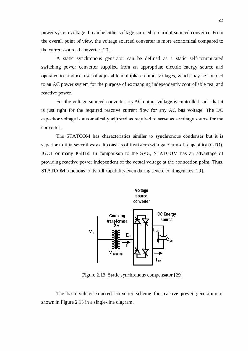
power system voltage. It can be either voltage-sourced or current-sourced converter. From
the overall point of view, the voltage sourced converter is more economical compared to
the current-sourced converter [20].
A static synchronous generator can be defined as a static self-commutated
switching power converter supplied from an appropriate electric energy source and
operated to produce a set of adjustable multiphase output voltages, which may be coupled
to an AC power system for the purpose of exchanging independently controllable real and
reactive power.
For the voltage-sourced converter, its AC output voltage is controlled such that it
is just right for the required reactive current flow for any AC bus voltage. The DC
capacitor voltage is automatically adjusted as required to serve as a voltage source for the
converter.
The STATCOM has characteristics similar to synchronous condenser but it is
superior to it in several ways. It consists of thyristors with gate turn-off capability (GTO),
IGCT or many IGBTs. In comparison to the SVC, STATCOM has an advantage of
providing reactive power independent of the actual voltage at the connection point. Thus,
STATCOM functions to its full capability even during severe contingencies [29].
Figure 2.13: Static synchronous compensator [29]
The basic-voltage sourced converter scheme for reactive power generation is
shown in Figure 2.13 in a single-line diagram.

24
2.4.2.2.a. STATCOM structure
The STATCOM is a power electronic based synchronous voltage generator (SVG) that,
from a dc capacitor, generates a three-phase voltage in synchronism with the transmission
line voltage, and it is connected to it by a coupling transformer. By controlling the
STATCOM’s output voltage magnitude, the reactive power exchanged between
STATCOM and the transmission system, and hence the amount of shunt compensation,
can be controlled. The basic STATCOM’s structure is presented on Figure 2.14. It
basically consists of a step-down transformer with a leakage reactance, a three-phase
voltage source converter (VSC), and a DC capacitor. The AC voltage difference across the
leakage reactance produces reactive power exchange between the STATCOM and the
power system, such that the AC voltage at the bus bar can be regulated to improve the
power system voltage profile, which is the STATCOM’s primary duty [31].
Figure 2.14: Configuration of STATCOM [31]
2.4.2.2.b. STATCOM operating principle
The VSC generates a controllable AC voltage behind the transformer’s leakage reactance.
This voltage is compared with the AC bus voltage system; when the AC bus voltage
magnitude is above that of the VSC voltage magnitude, the AC system sees the

84
REFERENCES
1. Bisen, P. & Shrivastava, A. (2013). Comparison between SVC and STATCOM
FACTS Devices for Power System Stability Enhancement. India: International
Journal of Emerging Technologies.
2. Padiyar, K. R. (2002). Power System Dynamic Stability and Control. 2nd ed.
Hyderabad, India: BS Publications.
3. Sahu, L. (2011). Modeling of STATCOM and Svc for Power System Steady State
Operation and Enhancement of Transient Stability of a Multi-Machine Power
System by STATCOM. Odisha, India: National Institute of Technology, Rourkela.
4. Meddeb, A., Jmii, H. & Chebbi, S. (2016). Comparison of UPFC, TCSC and SVC
for Improving Voltage Stability. Singapore: IPCO.
5. Wang, H. F. & Swift, F. J. (1997). A Unified Model for the Analysis of FACTS
Devices in Damping Power System Oscillations Part I: Single-machine Infinite-
bus Power Systems. IEEE Transactions on Power Delivery, 12(2).
6. Noroozian, M., Angquist, L., Ghandhari, M. & Andersson, G. (1997). Use of
UPFC for Optimal Power Flow Control. IEEE Transactions on Power Delivery,
12(4).
7. Wang, Y. P., Hur, D. R., Chung, H. H., Watson, N. R., Arrillaga, J., & Matair, S.
S. (2000). A Genetic Algorithms Approach to Design an Optimal PI Controller for
Static VAR Compensator. Australia: Power System Technology. Proceedings.
PowerCon. International Conference on, 3. IEEE.
8. Keshavan, B. K. & Prabhu, N. (2001). Damping of Sub-synchronous Oscillations
Using STATCOM - A FACTS Device. Transmission and Distribution Conference
and Exposition.
9. Lu, Y. & Abur, A. (2001). Improving System Static Security via Optimal
Placement of Thyristor Controlled Series Capacitors (TCSC). USA: Power
Engineering Society Winter Meeting. IEEE, 2, pp. 516-521.

85
10. Farsangi, M. M., Song, Y. H. & Lee, K. Y. (2004). Choice of FACTS Device
Control Inputs for Damping Interarea Oscillations. IEEE Transactions on Power
Systems, 19(2), pp 1135-1143.
11. Haque, M. H. (2004). Improvement of First Swing Stability Limit by Utilizing Full
Benefit of Shunt FACTS Devices. IEEE Transactions on Power Systems, 19(4), pp
1894-1902.
12. Hossam-Eldin, A. A., Elrefaie, H. & Mohamed, G. K. (2006). Study and
Simulation of the Unified Power Flow Controller Effect on Power Systems. Egypt:
The Eleventh International Middle Eastpom.
13. Nikoukar, J. & Jazaeri, M. (2007). Genetic Algorithm Applied to Optimal Location
of FACTS Devices in a Power System. Greece: Proc. of the 3rd IASME/WSEAS
Int. pp. 24-26.
14. Shaheen, H. I., Rashed, G. I. & Cheng S. J. (2008). Nonlinear Optimal Predictive
Controller for Static Synchronous Compensator (STATCOM). Chicago, USA:
Transmission and Distribution Conference and Exposition.
15. Sankar, S., Balaji, S. & Arul, S. (2010). Simulation and Comparison of Various
FACTS Devices in Power System. International Journal of Engineering Science and
Technology, 2(4), pp 538-547.
16. Murali, D., Rajaram, M. & Reka, N. (2010). Comparison of FACTS Devices for
Power System Stability Enhancement. International Journal of Computer
Applications, 8(4).
17. Ciausiu, F. E. & Eremia, M. (2011). Improvement of Power System Security
Margins by Using FACTS Devices. Norway: PowerTech, IEEE Trondheim.
18. Singh, S. K., Phunchok, L. & Sood, Y. R. (2012). Voltage Profile and Power Flow
Enhancement with FACTS Controllers. International Journal of Engineering
Research and Technology, 1(5).
19. Vijayan, A. & Padma, S. (2013). Maintaining Voltage Stability in Power System
using FACTS Devices. International Journal of Engineering Science Invention,
2(2).
20. Hingorani, N. H. & Gyugyi, L. (2000). Understanding FACTS: Concepts and
Technology of Flexible AC Transmission Systems. 1st ed. Wiley-IEEE Press.
21. Subramanian, S. S. (2010). Effects Of Flexible Ac Transmission System (Facts) On
The Performance Of Distance Protection Relays. Staffordshire University: Ph.D.
Thesis.
22. Song, Y. H. & Johns, A. T. (1999). Flexible AC Transmission Systems. London,
UK: Institution of Electrical Engineers.

86
23. Zhang, L. (2006). Study of FACTS/ESS Applications in Bulk Power System.
Virginia Polytechnic Institute and State University: Ph.D. Thesis.
24. Cheng, E. (2014). Power Electronics for Utility Applications (EE529). Hong
Kong: Polytechnic University.
25. Rahman, M. B. A.. Overview of Thyristor Controlled Series Capacitor (TCSC) In
Power Transmission System.
26. Panda, S. & Padhy, N. P. (2007). Thyristor Controlled Series Compensator- based
Controller Design Employing Genetic Algorithm: A Comparative Study.
International Journal of Electronics, Circuits and Systems, 1.
27. Gyugyi, L., Schauder, C. D. & Sen, K. K. (1997). Static Synchronous Series
Compensator: A Solid-State Approach to the Series Compensation of Transmission
Lines. IEEE Transaction on Power Delivery, 12.
28. Voraphonpiput, N., Bunyagul, T. & Chatratana, S. (2008). Power Flow Control
with Static Synchronous Series Compensator (SSSC). USA: International Energy
Journal, 9.
29. Zhang, X. P., Rehtanz, C. & Pal, B. (2012). Flexible AC Transmission Systems:
Modelling and Control. Germany: Springer Berlin Heidelberg.
30. Sabai, N., Maung, H. N. & Win, T. (2008). Voltage Control and Dynamic
Performance of Power Transmission System Using Static Var Compensator.
World Academy of Science, Engineering and Technology, 42, pp. 426.
31. TM T&D Corporation. STATCOM. Japan: Instruction Booklet.
32. Grag, A. & Agarwal, S. K. (2012). Voltage Control and Dynamic Performance of
Power Transmission System Using STATCOM and Its Comparison with SVC.
International Journal of Advances in Engineering & Technology (IJAET), 2(1), pp.
437-442.
33. Georgilakis, P. S. & Vernados, P. G. (2011). Flexible AC Transmission System
Controllers: An Evaluation. Switzerland: Trans Tech Publications.
34. Karthik, B. (2007). Modeling Studies of Inter Line Power Flow Controller for
Multi Line Transmission System. Tamil Nadu, India: IET-UK International
Conference on Information and Communication Technology in Electrical
Sciences. pp. 475-479.
35. Gyugyi, L. (1992). A unified Power Flow Control Concept for Flexible AC
Transmission Systems. IEE proceedings-C, 139(4).
36. Gyugyi, L. (2003). Unified Power Flow Control Concept for Flexible AC
Transmission Systems Generation. Proc. Transmission Distribution conference,
139, pp. 323-331.

87
37. Gyugyi, L., Schauder, C. D., Williams, S. L., Rietman, T. R., Torgerson, D. R. &
Edris, A. (1995). The Unified Power Flow Controller: a New Approach to Power
Transmission Control. IEEE Transactions on Power Delivery, 10(2), pp. 1085-
1097.
38. Li, Q. (2006). Analysis, Design, And Laboratory Evaluation Of A Distributed
Unified Power Flow Controller Concept. University of Kentucky: Ph.D. Thesis.
39. Schauder, C. D., Gyugyi, L., Lund, M. R., Hammai, M. D., Reitman, T. R.,
Torgerson, D. R. & Edris, A. (1998). Operation of Unified Power Flow Controller
under 174 Practical Constraints. IEEE Transactions on power delivery, 13(2), pp.
630-637.
40. P. Kundur, 1994. Power System Stability and Control, McGraw-Hill, Example
12.6, p. 813.