modeling the storage architectures of commercial database systems
TRANSCRIPT

Modeling the Storage Architectures of Commercial Database Systems
D. S. BATORY The University of Texas at Austin
Modeling the storage structures of a DBMS is a prerequisite to understanding and optimizing database performance. Previously, such modeling was very difficult because the fundamental role of conceptual-to-internal mappings in DBMS implementations went unrecognized.
In this paper we present a model of physical databases, called the transformation model, that makes conceptual-to-internal mappings explicit. By exposing such mappings, we show that it is possible to model the storage architectures (i.e., the storage structures and mappings) of many commercial DBMSs in a precise, systematic, and comprehendible way. Models of the INQUIRE, ADABAS, and SYSTEM 2000 storage architectures are presented as examples of the model’s utility.
We believe the transformation model helps bridge the gap between physical database theory and practice. It also reveals the possibility of a technology to automate the development of physical database software.
Categories and Subject Descriptors: E.5 [Data]: Files-organization/structure; H.2.2 [Database Management]: Physical Design--access methods
General Terms: Design Documentation
1. INTRODUCTION Optimizing the performance of commercial database systems is a significant and very difficult problem. Progress toward its solution has come from models of physical databases (i.e., models of database storage structures and their associated search and maintenance algorithms). Since 1970 there have been important advances in file structure and physical database modeling. These advances, as a rule, have been incorporated into a progression of increasingly more sophisticated and realistic general-purpose models [6, 29, 41, 55, 67, 68, 881.
In spite of progress, there still is no model that can account for the diversity and complexity of storage structures and algorithms found in commercial DBMSs in a comprehendible way. Although some models have been used as starting points, considerable effort is needed to adapt and extend them just to describe a single DBMS ([El). In view of these difficulties, it is easy to understand why there are so few design and performance aids for commercial systems ([33, 341).
This work was supported by the National Science Foundation under grant MCS-8317353 and the U.S. Department of Energy under contract DE-A505-81ER10977. Permission to copy without fee all or part of this material is granted provided that the copies are not made or distributed for direct commercial advantage, the ACM copyright notice and the title of the publication and its date appear, and notice is given that copying is by permission of the Association for Computing Machinery. To copy otherwise, or to republish, requires a fee and/or specific permission. 0 1985 ACM 1730.0301/85/1200-0463 $00.75
ACM Transactions on Database Systems, Vol. 10, No. 4, December 1985, Pages 463628.

464 l D. S. Batory
The problems in using current models clearly indicate that some fundamental principles of database system implementation are not well understood. A careful examination of several commercial DBMSs reveals that current models presume conceptual-to-internal mappings are simple. That is, given a set of conceptual files and links, there is an obvious mapping to their internal counterparts. In almost all commercial and specialized DBMSs this is definitely not the case.
In this paper we present the transformation model (TM), a model of physical databases that makes conceptual-to-internal mappings explicit. We id.entify a set of primitive mappings, called elementary transformations, and show how com- positions of these transformations can be used to accurately express the storage architectures of operational DBMSs. By storage architecture we mean the com- bination of conceptual-to-internal mappings, file structures, and record-linking mechanisms that define a physical database. As examples of the TM’s practical- ity, we show how the diverse and complex storage architectures that underlie three commercial DBMSs-namely, INQUIRE, ADABAS, and SYSTEM 2000- can be defined in a precise, systematic, and simple way. Models of other com- mercial DBMSs-relational (MRS, INGRES), network (IDMS, DMS-llOO), and statistical (RAPID, ALDS, CREATABASE)-are presented in [7, 81 and [9]. A preliminary model of IMS has also been developed ([S]).
A primary goal of this paper is to explain conceptual-to-internal mappings of data. Mappings of operations (e.g., record retrieval, insertion, deletion) are discussed only briefly, but are considered in more detail in [9] and [86].
We believe our research makes four main contributions: (1) it is a step toward the development of practical design and tuning aids for operational DBMSs; (2) it provides a basis for a technology to automate the development of physical database software; (3) it introduces practical tools to design, communicate, and understand prototype storage architectures; and (4) it signals the beginning of a comprehensive reference to the storage architectures of commercial DBMSs. These and other contributions are discussed in Section 5.
The starting point of our research is the Unifying Model (UM) of Batory and Gotlieb [6]. In the following section we review the basic concepts of the UM and its subsequent extensions. We explain in Appendix I how these extensions subsume earlier studies, thereby establishing the UM as a framework in which most, if not all, contributions to file and physical database research may even- tually be cast. Special attention is given to show how the UM can be reduced to DIAM ([29, 671). In the following section we present an example which clearly reveals the limitations of the generalized UM (and its predecessors) and motivates the study of conceptual-to-internal mappings.
2. THE UNIFYING MODEL: A GENERALIZATION
The UM was shown to relate and extend disparate works on file design and optimization, transposed files, batched searching, index selection, and file reor- ganization, among others. However, the UM could not account for certain classes of storage structures (e.g., clustering and hierarchical sequential record linkages) that are commonly found in commercial DBMSs. Nor did it distinguish between the logical concepts of files and links and their physical implementations (i.e., simple files and linksets). In the following paragraphs we explain a generalization ACM Transactions on Database Systems, Vol. 10, No. 4, December 1985.

Modeling Storage Architectures 465
of the UM framework that makes these important distinctions and accommodates these structures. Additional details are presented in Appendix II.
Physical databases can be decomposed into a collection of internal files and internal links. An internal file is a set of records that are instances of a single record type. A relationship between two or more internal files is an internal link. Internal links can be understood as generalizations of CODASYL sets; each internal link relates records of one file, called the parent file, to records of other files, called child files. (We draw a distinction here between conceptual files and links, which are defined in database schemas, from internal files and internal links. We will see later that they are quite different.)
The basic structures of a physical database are simple files and linksets. A simple file is a structure that organizes records of one or more internal files. Classical simple file structures include hash-based, indexed-sequential, B+ trees, dynamic hash-based, and unordered files. A linkset is a structure that implements one or more internal links. Classical linkset structures include pointer arrays, inverted lists, ring lists, and hierarchical sequential lists. Linksets also deal with the clustering of child records around their parent records (i.e., sequential placement or [24] or “store near” [22]). Catalogs of recognized simple files and linksets are given in Appendix II.
The structure of a physical database can therefore be specified by (1) decom- posing the database into its internal files and links and (2) assigning each internal file to a simple file structure and each internal link to a linkset structure. Classical examples of decomposition are presented in the next section, along with the introduction of notation which will be used extensively later.
2.1 Examples: Decomposition of Inverted and Multilist Files
Inverted and multilist files are classical file structures, but they are not simple file structures. Rather, they are actually networks on interconnected files that have special implementation connotations.
Consider a file of records of type DATA. Suppose DATA records are stored in an inverted file where attributes Fj and Fk are indexed. The first step in defining the implementation of the inverted file is to decompose it. Decomposition reveals three internal files and two internal links. One file is the DATA file; the other two are INDEXj and INDEXk, one file for each of the indexed attributes. Each INDEX file is connected to the DATA file by precisely one link, where the INDEX file assumes the role of parent. Relationships between files and links are shown graphically in a data structure diagram (dsd) where boxes represent files and arrows denote links. (Arrows are drawn from parent files to their child files). Figure l.dsd (abbreviation for the dsd of Figure 1) shows the decomposition of the inverted file. The remaining parts of Figure 1 are explained in the next section.
The second step is to assign implementations to the internal files and links. A common assignment has each INDEX file organized by a distinct B+ tree, and the DATA file organized by an unordered file structure. Thus, there is a total of three simple files (i.e., a DATA file structure and two INDEX file structures). The internal links would be implemented by inverted lists or pointer arrays.
Note that other simple file assignments are possible. For example, one INDEX file could be implemented by an unordered file, the other by an indexed-sequential
ACM Transactions on Database Systems, Vol. 10, No. 4, December 1985.

466 l D. S. Batoty
dsd -
DATA
fdd - fl
Fig. 1. Decomposition of an inverted file.
DATA
fdd id - -
Fig. 2. Decomposition of a multilist file.
file, and the DATA file might be stored in a hash-based file. Such generalizations follow naturally from decomposition. (INGRES, incidentally, is based on inverted files and allows such implementation possibilities [76]).
Now consider another example. Suppose DATA records are stored in a multilist file, where again fields Fj and Fk are indexed. Decomposition results in the same data structure diagram as in the inverted file example (Figure 2.dsd). Further- more, typical multilist file implementations are quite similar to inverted file implementations: each INDEX file is organized by a distinct B+ tree, and the DATA file is organized by an unordered file structure. However, the link imple- mentations are different: multilist files use multilist (i.e., list) linksets.
It is worth noting that the INDEX files of inverted and multilist files corre- spond to secondary indices. The term primary index has been used by some researchers to mean the indexing structure that directs the clustering of internal records on their primary key. We prefer to use the term cluster index instead, since a cluster index is actually part of a simple file structure, as opposed to being a distinct file as is the case with secondary indices. In the UM, every simple file is a combination of a cluster index and an internal record storage structure, called the data level. Thus, B+ trees, indexed-sequential, dynamic hash-based structures, etc., all have a clearly identifiable cluster index and data level. This means in the above examples that a primary index (cluster index) is provided automatically to each INDEX file and DATA file by virtue of being organized by ACM Transactions on Database Systems, Vol. 10, No. 4, December 1985.

Modeling Storage Architectures 467
a simple file structure. It is in this way that the UM handles the concept of primary indices.
Implementations of physical databases can be described in further detail by introducing additional diagrammatic notations and by extending the conventions of data structure diagrams to express N:M links. This is done in the following section.
2.2 Additional Background
Two other diagrams are useful in elaborating implementation details of physical databases. One is a field definition diagram (fdd), which shows the fields of the record types that appear in a data structure diagram. Consider again the inverted file of Figure 1. Figure l.fdd (abbreviation for the fdd of Figure 1) shows the DATA record type to consist of fields F1 . . . F,,. It also shows the INDEXj record type to have two fields: a data field Fj and an inverted list field P+. We refer to P1, as the parent field of linkset I,. The INDEXk type has a format similar to INDEX,.
The other diagram is an instance diagram (id), which is used to illustrate the implementation of one or more link occurrences. A link occurrence consists of a single parent record and the zero or more child records to which it is related. Instance diagrams serve to further elaborate data structure and field definition diagrams. To minimize the clutter in instance diagrams, records are not labeled with their types. Instead the types can be inferred by their positions or contents relative to the associated fdd or dsd. Figure Lid (abbreviation for the id of Figure 1) shows the implementation of an Ij link occurrence. An INDEXj record is shown containing data value Uj and an inverted list which references all DATA records (three are shown) that have Uj as their Fj value. An instance diagram of an Ik link occurrence implementation would be drawn identically to that of Figure l.id, except for the labeling (uk would be used to denote a Fk value). In cases such as this, where instance diagrams would be duplicated, we show only one.
The field definition and instance diagrams for the multilist file are shown in Figures 2.fdd and 2.id. Note that Figure 2.fdd shows DATA records to have two additional fields Cl, and C1,. These fields are, respectively, the child fields of linksets Ij and Ik. Their purpose is to contain pointers to the next DATA record on a list of DATA records. Figure 2.id shows the same link occurrence of Figure l.id, except that a list structure connects an INDEXj record to its DATA records.
We use the terms parent field and child field as generic names to refer to fields that must be present in parent and child records, respectively, in order to realize particular linkset structures. Some parent and child fields have common names, such as inverted list fields and parent pointer fields. But most do not. Another reason for their use is that they define semantically meaningful fields whose contents can be quite complex. The parent field of an inverted list, for example, not only contains an array of pointers, but also a count subfield which contains the number of pointers in the array and possibly the length of the array in bytes. By treating parent and child fields atomically, implementation details of linksets that are irrelevant to understanding storage architectures can be hidden.
As a general rule, the presence and function of parent and child fields in record types that are linked is determined solely by the underlying linkset. In the case of inverted list linksets (Fig. l), a parent field appears in every parent record.
ACM Transactions on Database Systems, Vol. 10, No. 4, December 1985.

468 ’ D. S. Batory
For multilists (Fig. 2), both parent and child fields are used. IMS logical parent pointers are linksets that are implemented solely by parent pointers [24]; only child fields are used. Sequential linksets do not require either parent or child fields (i.e., parent and child records are linked by contiguity). Thus, a linkset can introduce parent fields, child fields, both, or neither.
The pointer structures, count fields, and so on that are present in parent fields are usually different than those found in child fields. As a consequence, linksets have a directionality (i.e., parent and child files of a linkset must be distinguished in order to determine the placement of the parent and child fields of the linkset). Links, in contrast, express logical relationships which do not have a directionality. Thus, the directionality of links (arrows) in data structure diagrams serve to indicate the roles files play in link implementations.
Assigning the directionality of links in data structure diagrams is quite simple. Most linksets implement l:N links. In the tradition of the CODASYL model, 1:N links are represented by arrows drawn in the direction of the “N” part of the relationship; the file at the “1” side is the parent and those at the “N” side are the children. We follow this tradition. However, links can also express 1:l and M:N relationships. Usually, the linksets that implement these links are obvious generalizations or specializations of 1:N linksets, so a directionality can be assigned as in the 1:N case. We encounter an example of this (M:N multilists) in our discussion of INQUIRE in Section 4. When neither child or parent fields are introduced by a linkset or when no distinction between parent and child files can be made, bidirectional links (A t3 B) which do not force parent and child distinctions may be used. Examples of bidirectional links arise in our discussions of transposition and actualization in Section 3, and the couplings of ADABAS in Appendix III.
In Appendix I we explain how all of the major general-purpose models of physical databases that predated the UM are subsumed by this framework. Even so, this framework is still inadequate to model the storage architectures of operational DBMSs. Correcting the problem does not simply involve enlarging the spectrum of structures and operations the UM describes. It requires much more. The next section illustrates the limitations of this framework.
2.3 Limitations of Current Models
Consider the inverted file of Figure 3, which has a single INDEX file that inverts field F. INDEX records are obviously variable-length. But suppose that the file structures that underlie the inverted file can only handle fixed-length records. How can variable-length INDEX records be stored?
A common solution (one of many possible) is to divide INDEX records into one or more fixed-length fragments. The first fragment, here called a PRIMARY record, contains the data field F and a number of pointers. The other fragments are SECONDARY records (sometimes called overflow records), and they contain the remaining pointers. PRIMARY and SECONDARY records are connected by link L. L is usually implemented as a list linkset.
Figure 4 illustrates this solution using some notation and relationships that are explained in a more comprehensive setting in Section 3. In Figure 4.dsd, the dashed outline of the INDEX file indicates that an INDEX record is mapped to a PRIMARY record and zero or more SECONDARY records connected via ACM ‘hmsactions on Database Systems, Vol. 10, No. 4, December 1985.

Modeling Storage Architectures l 469
dsd -
INDEX ,-_---_ ----------- _._- - I
I____---------_-______I
DATA
II p-py-q . . . Iy(
INDEX
ul F PI
fdd id - -
Fig. 3. An inverted file with one index file.
PRIMARY
[FltP,I
SECONDARY
ccl +P, CL
to DATA records
dsd - fdd - g
Fig. 4. Mapping of variable-length INDEX records to fixed-length PRIMARY and SECONDARY records.
link L. +-PI in Figure 4.fdd is the name of the field (in both PRIMARY and SECONDARY) that contains a fragment of the contents of field PI. Figure 4.id shows how the INDEX record of Figure 3.id was divided into four fragments: one PRIMARY and three SECONDARY. SECONDARY records are connected to PRIMARY records by a list linkset. In this example both PRIMARY and SECONDARY records contain pointers (part of PI) to DATA records.
This example reveals that there is a level of abstraction that separates an INDEX record from its materialization as a PRIMARY and zero or more SECONDARY records. It is easy to draw data structure, field definition, and instance diagrams that occur at each level. Figure 3 shows the diagram at the upper level; Figure 4 shows the lower level. Such levels of abstraction are not present in the generalized UM or any of its derivatives and predecessors. Unless levels of abstraction are introduced, one is forced to model the inverted tile in a single (one level of abstraction) data structure diagram. Figure 5 shows the difficulties that arise when this is tried. It is easy to identify the three internal files PRIMARY, SECONDARY, and DATA. It is also easy to identify link L which connects PRIMARY to SECONDARY. But what about link I? Since the pointers that define the parent field (i.e., inverted list) of link Z are strewn over
ACM Transactions on Database Systems, Vol. 10, No. 4, December 1985.

470 ’ D. S. Batory
L PRIMARY
Fig. 5. The need for multiple levels of abstraction.
PRIMARY and SECONDARY records, how is one to decide the parent record of a link I occurrence? What is the parent file of link I? Three possible ways are shown in Figure 5, but it is obvious that none conveys the correct structure or relationship.
The general problem is clear. Elementary storage structures can be used to implement other elementary storage structures (e.g., list linksets are used to implement inverted list linksets). Levels of abstraction are needed to separate these structures in order to describe them in a meaningful way.
New modeling techniques, quite different from those used previously, are needed to account for the above implementation possibilities and to predict their generalizations. Central to these techniques is the idea of conceptual-to-internal mappings.
3. THE TRANSFORMATION MODEL
A primary function of a DBMS is to map conceptual files and operations to their internal counterparts. INGRES [76], for example, maps relations and relational operations onto inverted files. SYSTEM R [24] and RAPID [83] also begin with relations, but SYSTEM R maps to inverted files with record clustering and RAPID maps to transposed files.
An intuitive understanding of conceptual-to-internal mappings is gained by recognizing a mapping as a sequence of database definitions that are progressively more implementation-oriented. The sequence begins with definitions of the conceptual files and their links, and ends with definitions of the internal files and their links. Each intermediate definition contains both conceptual and internal elements, and thus can be identified with a level of abstraction that lies between the “pure” conceptual and “pure” internal levels. In this way physical databases can be modeled at different levels of abstraction.
Distinguishing different levels in a DBMS and mapping from one level to an adjacent level is usually straightforward. In the DBMSs that the author has studied, only ten different primitive mappings, henceforth called elementary transformations, have been utilized. Elementary transformations can be used singly or in combination to map files and links from one level of abstraction to a lower level. In principle, this means that the conceptual-to-internal mappings of a software-based DBMS can be modeled by (1) taking the generic conceptual files and links that the DBMS supports and (2) applying a well-defined sequence of elementary transformations to produce the internal files and links of the DBMS. In the case of INGRES, SYSTEM R, and RAPID, all begin with the ACM Transactions on Database Systems, Vol. 10, No. 4, December 1985.

Modeling Storage Architectures l 471
same conceptual files (i.e., relations), but each is distinguished by different sequences of transformations (and hence different sets of internal files and links). We explain each of the elementary transformations in detail shortly.
Conceptual-to-internal mappings are related to the UM in the following way. The UM relies on decomposition to identify the internal files and links of a physical database. In contrast, the TM starts with conceptual files and links that are supported by a DBMS and shows how their underlying internal files and links are derived. The TM does not introduce new simple file structures or linkset structures. Rather, the TM extends the UM by supplanting the intuitive process of physical database decomposition with conceptual-to-internal mappings. Thus, the primitives for describing DBMS architectures are (1) simple files, which map internal files to pages on secondary storage; (2) linksets, which specify how related records of different files are physically connected, and (3) elementary transformations, which define how abstract (or higher level) files and links are mapped to concrete (or lower level) files and links.
It is important to recognize that conceptual-to-internal mappings and elemen- tary transformations are not artificial concepts. Each elementary transformation can be realized by a simple layer of software. In turn, the physical database software of a DBMS can be understood as a sequence of these layers, where the software of different DBMSs are described by different sequences. The idea of “level of abstraction” corresponds to the files and links of a DBMS that are visible at a particular level in its software. Thus, conceptual-to-internal mappings and elementary transformations are fundamental to the way DBMS software is actually written or can be written. We explain in Section 5 how the TM is being used to develop a system whose goal is to automate the development of the physical database software of DBMSs.
3.1 Elementary Transformations
Elementary transformations are rules for mapping files and links at one (higher) level of abstraction to those at the next lower (more concrete) level. Ten elementary transformations are presently recognized. They were discovered as a consequence of studying the storage architectures of SPIRES [74], DMS-1100 [73], TOTAL [20], MRS [49], IDMS [22], INGRES [76], IMS [44], ADABAS [32], INQUIRE [45], RAPID [83], ALDS [14], CREATABASE [61], and SYS- TEM 2000 [16]. Models of the storage architectures for most of these systems have been completed. Table I lists the transformations that are used in each model, and a reference to the model. Preliminary models of the remaining systems-IMS, TOTAL, SPIRES, and CREATABASE-are given in [8]. Al- though there is ample evidence that the transformations identified in this paper are the most common, there may be other transformations which have not yet been recognized. We address the completeness issue later in Section 5.
The transformations themselves were defined to coincide with familiar phys- ical database concepts or with their generalizations. For example, there is a transformation called segmentation which corresponds to the well-known concept of segmentation [56]. Thus, there is reason to believe that similar sets of transformations would have been identified if models of conceptual-to-internal mappings had been developed independently of our research.
ACM Transactions on Database Systems, Vol. 10, No. 4, December 1985.

472 - D. S. Batory
Table I. Usage of Elementary Transformations in Existing Models
Database Management System
Elementary DMS- SYSTEM transformation ADABAS ALDS 1100 IDMS INGRES INQUIRE MRS RAPID 2000
Augmentation Encoding Extraction Collection Segmentation Division Actualization Layering Null Horizontal
partitioning
Model reference
x
X
X
X
X
X
X
Appendix III
X X X x x x
X X X
X X X X
X
X X X X X X
X X x X
X X
X X X X
PI PI [71 L91 Sect. 4 [71 PI
X
X
Appendix IV
Fig. 6. Two materializa- tions of abstract file W.
W W
F
x L
G
(4 (b)
F’
z L’
G’
To illustrate and explain the effects of each transformation, we again use data structure, field definition, and instance diagrams. Besides the usual conventions, there are two additions. First, abstract objects (typically files) are indicated by dashed outlines in data structure diagrams. Figure 6a shows a data structure diagram of an abstract file W and its materialization as the files F and G and link L. Figure 6b shows another example materialization of Was the files F’ and G’ and link L’, where L’ has opposite directionality.
Second, pointers to abstract records arise naturally in storage architectures. In order to give such pointers a physical realization (i.e., a physical address or symbolic key), they must ultimately reference internal records. To define how pointer references are transformed, we rely on the orientation of record types within a dsd. The orientation of F and G in Figure 6a, for example, shows that file F is above file G. We say that F dominates G. This means that a pointer to an abstract record of type W will actually reference its corresponding concrete ACM Transactions on Database Systems, Vol. 10, No. 4, December 1985.
Modeling Storage Architectures 473
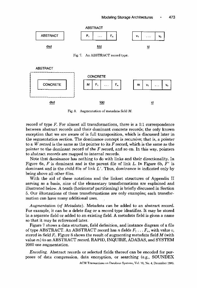
ABSTRACT
dsd - fdd - id -
Fig. 7. An ABSTRACT record type.
ABSTRACT
Fig. 8. Augmentation of metadata field M.
record of type F. For almost all transformations, there is a 1:l correspondence between abstract records and their dominant concrete records; the only known exception that we are aware of is full transposition, which is discussed later in the segmentation section. The dominance concept is recursive; that is, a pointer to a W record is the same as the pointer to its F record, which is the same as the pointer to the dominant record of the F record, and so on. In this way, pointers to abstract records are mapped to internal records.
Note that dominance has nothing to do with links and their directionality. In Figure 6a, F is dominant and is the parent file of link L. In Figure 6b, F’ is dominant and is the child file of link L’. Thus, dominance is indicated only by being above all other files.
With the aid of these notations and the linkset structures of Appendix II serving as a basis, nine of the elementary transformations are explained and illustrated below. A tenth (horizontal partitioning) is briefly discussed in Section 5. Our illustrations of these transformations are only examples; each transfor- mation can have many additional uses.
Augmentation (of Metadata). Metadata can be added to an abstract record. For example, it can be a delete flag or a record type identifier. It may be stored in a separate field or added to an existing field. A metadata field is given a name so that it may be referenced later.
Figure 7 shows a data structure, field definition, and instance diagram of a file of type ABSTRACT. An ABSTRACT record has n fields Fl . . . F,, with value Ui stored in field Fi. Figure 8 shows the result of augmenting metadata field M (with value m) to an ABSTRACT record. RAPID, INQUIRE, ADABAS, and SYSTEM 2000 use augmentation.
Encoding. Abstract records or selected fields thereof can be encoded for pur- poses of data compression, data encryption, or searching (e.g., SOUNDEX
ACM Transactions on Database Systems, Vol. 10, No. 4, December 1985.

474 l D. S. Batory
ABSTRACT
dsd fdd - - id -
Fig. 9. Encoding of individual fields,
ABSTRACT
CONCRETE
/ (CONCRETE1 -1 ( El V’
I I L-----------------J
dsd - fdd - id -
Fig. 10. Encoding of an entire record.
encoding [85]). Common data compression algorithms include the elimination of trailing blanks and leading zeros, storing numeric character strings as binary integers, digraph encoding schemes (where commonly occurring character pairs are encoded into single bytes [84]), Huffman encoding [43], and Ziv-Lempel encoding [89]. Well-known encryption algorithms are block ciphers [52] and the NBS data encryption standard [60].
Encodings are applied to individual fields or to entire records (viewed just as a string of bytes). The former allows direct access to compressed fields and compressed data values, the latter requires record expansion before specific fields can be located. Figures 9 and 10 illustrate the notation that is used to distinguish these cases on the ABSTRACT record of Figure 7. Figure 9.fdd shows unencoded field Fi mapped to encoded field F,f , and Figure lO.fdd shows the string of fields Fl . . . F,, mapped to a single encoded field F’. ADABAS compresses fields separately; IDMS compresses entire records.
Note that some encoding schemes, such as Huffman and Ziv-Lempel encod- ings, require the use of translation tables. These tables would be maintained by the system as part of the internal representation of the schema in which the ABSTRACT record type was defined. Such tables are not shown in the diagrams of Figures 9 and 10.
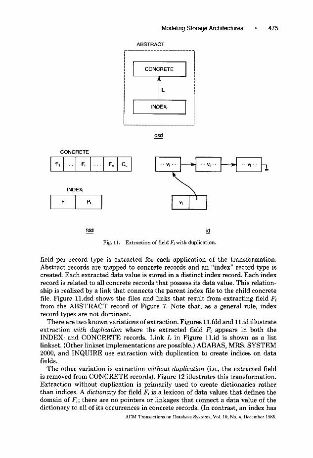
Extraction. Creating a secondary index on a field of an abstract record type is one of several uses of extraction. The basic idea is to extract the set of all distinct data values that appear in specified fields of abstract records.’ Normally, one
’ Compound fields may also be extracted. A compound field is an ordered sequence of two or more elementary fields.
ACM Transactions on Database Systems, Vol. 10, No. 4, December 1985.
Modeling Storage Architectures l 475
ABSTRACT
i----------------------.
dsd -
CONCRETE
Fq . . Fi . . . Fn CL
INDEXi \
fdd - id -
Fig. 11. Extraction of field F, with duplication.
field per record type is extracted for each application of the transformation. Abstract records are mapped to concrete records and an “index” record type is created. Each extracted data value is stored in a distinct index record. Each index record is related to all concrete records that possess its data value. This relation- ship is realized by a link that connects the parent index tile to the child concrete file. Figure Il.dsd shows the files and links that result from extracting field Fi from the ABSTRACT record of Figure 7. Note that, as a general rule, index record types are not dominant.
There are two known variations of extraction. Figures ll.fdd and ll.id illustrate extraction with duplication where the extracted field Fi appears in both the INDEXi and CONCRETE records. Link L in Figure ll.id is shown as a list linkset. (Other linkset implementations are possible.) ADABAS, MRS, SYSTEM 2000, and INQUIRE use extraction with duplication to create indices on data fields.
The other variation is extraction without duplication (i.e., the extracted field is removed from CONCRETE records). Figure 12 illustrates this transformation. Extraction without duplication is primarily used to create dictionaries rather than indices. A dictionary for field Fi is a lexicon of data values that defines the domain of Fi; there are no pointers or linkages that connect a data value of the dictionary to all of its occurrences in concrete records. (In contrast, an index has
ACM Transactions on Database Systems, Vol. 10, No. 4, Dewmber 1985.

476 ’ D. S. Batoty
ABSTRACT r---------------------
dsd -
CONCRETE
F, . . . Fi-1 CL Fi+l . . . F”
iJ Vi
fdd id - -
Fig. 12. Extraction of field F, without duplication.
such linkages). Link L in Figure 12.id is implemented solely by parent pointers (i.e., pointers from child records to parent records). CREATABASE, ALDS, and RAPID use extraction without duplication to create dictionaries on data fields.
It is usually the case that DBMSs allow most, if not all, fields to have dictionaries or secondary indices. This can be modeled by repeated applications of extraction, once for each specified field. To indicate multiple extractions in a compact way, we use a special notation. In Figure 13.dsd, ( )j is used to indicate that the INDEX, file and its link 4 can be reproduced any number of times, each time with a different value for j.
When multiple links are generated, multiple child fields (one for each link) may be introduced to the CONCRETE record. In Figure 13.fdd, the presence of multiple child fields in the CONCRETE record type is shown by (CIj)j, where, again, ( )j is the repeat notation. The repeat notation is also used in Figure 13.fdd to indicate the generation of multiple INDEXj record types. There is, of course, an implicit coordination between data structure and field definition diagrams which use the repeat notation (i.e., the values of j used in the dsd are identical to those used in the fdd).
Some additional points need to be stressed. First, whenever a link is introduced by a transformation, it may be realized in principle by any linkset structure- ACM Transactions on Database Systems, Vol. 10, No. 4, December 1985.

Modeling Storage Architectures 477
ABSTRACT
CONCRETE
fdd - id -
Fig. 13. The repeat notation.
list, pointer array, sequential, or relational (see Appendix II). As mentioned previously, ADABAS, MRS, SYSTEM 2000, and INQUIRE use extraction with duplication. The link that is produced is realized by pointer arrays (inverted lists) in ADABAS, MRS, and SYSTEM 2000; it is realized by lists in INQUIRE.
Second, we use the term “extraction” rather than “indexing” since this trans- formation is used for purposes other than creating indices (e.g., dictionaries and phantom files [85]).
Third, the extraction transformation can be applied to derived fields (i.e., fields that are not actually present in a record, but whose value(s) can be computed by applying an “extraction” function to the record itself, see [78], [77], [82], [63]). A simple example of a derived field would be the calculation of monthly salaries, given yearly salaries. As a more complicated example, a text field could be “indexed” by applying a function to the field which returns the set of key words that it contains. An index record would then be defined for each distinct key word. As another example, a record could describe an object located on a circuit diagram. To support window retrieval (i.e., retrieval of all components of a diagram that fall within a specified geometric region), a circuit is partitioned into subcells. An “extraction” function applied to a record would produce the set of subcells in which its corresponding object lies. These subcell references could
ACM Transactions on Database Systems, Vol. 10, No. 4, December 1985.

478 . D. S. Batoty
ABSTRACT r-------------------
1
I
dsd -
CONCRETE CONCRETE CONCRETE record 2 ---) record 3
. . .
fdd - id -
Fig. 14. Collection.
then be used to optimize window retrieval [36]. Notions of extraction with and without duplication are extended accordingly.
Collection. The DBTG concept of a singular set, which links together all records of a given type, is an example of the collection transformation. The basic idea is to collect all instances of one or more abstract record types together onto a single link occurrence. Figure 14 shows the result of collecting the ABSTRACT record type of Figure 7. Note that the parent record of the lone L occurrence is maintained as part of the internal representation of the schema in which the ABSTRACT record type was defined. It is indicated by “J’ in Figure 14.dsd.
In all applications of collection known to the author, link L has been realized by a list linkset (see Fig. 14.id), although other linksets conceivably might be used.’ INQUIRE and SYSTEM 2000 use this transformation.3
Segmentation. Abstract records can be partitioned along one or more field boundaries to produce two or more subrecords. One subrecord is distinguished as the primary record, the rest are secondary records. A link connects the primary file to each secondary file. Primary records are differentiated from secondary records as they are materialized and processed differently. Usually it is the case
’ A rather odd implementation of link L would be as a sequential linkset. The system record l would be immediately followed by all CONCRETE record occurrences. Note that the resulting linkset occurrence does not define a simple file structure. The l record could be stored in a hash-based, indexed-sequential, etc., structure and its train of CONCRETE records would then follow. Linksets connect parent records to their child records; simple file structures map records into blocks. 3 A generalization of collection was proposed in DIAM [67]. It would collect all records (of possibly several types) that satisfy a predicate onto a single link occurrence.
ACM Transactions on Database Systems, Vol. 10, No. 4, December 1985.

Modeling Storage Architectures
ABSTRACT
dsd - fdd -
Fig. 15. Segmentation without duplication.
ABSTRACT
PRIMARY
/
PRIMARY
F, . . Fj . . Fk PL
SECONDARY
Fi f=k+l . . . F. CL
dsd - fdd -
Fig. 16. Segmentation with duplication.
id -
v, . . . vj ... vk
id -
that the most active fields (i.e., the ones that are retrieved and updated most frequently) are placed in the primary record and the remaining are in the secondary [56].
Segmentation can occur with or without duplication of data fields. Figure 15 shows the segmentation of fields F1 . . . Fk from Fk+l . . . F,, of the ABSTRACT record of Figure 7. No fields are duplicated, and L is shown as a singular pointer (i.e., a pointer array with precisely one child pointer) and a parent pointer. The same segmentation occurs in Figure 16, except that field Fj is duplicated. RAPID and IMS use segmentation with duplication; ADABAS and INGRES use seg- mentation without duplication.
Two forms of segmentation without duplication are so well-known or occur so frequently that they have been given special names. One is full transposition, which segments each field into separate subfiles. That is, if there are n fields in an abstract record type, then a full transposition produces n concrete record types, each containing precisely one field (see Figure 17). Because all fields are
ACM Transactions on Database Systems, Vol. 10, No. 4, December 1985.

480 D. S. Batory
ABSTRACT r----------------------------------- I 1
1 y+:-IICON;RETL1 ( I L I I I L-----------------------------------~
dsd -
I=,...”
fdd -
Fig. 17. Full transposition.
id -
treated identically, the resulting concrete types are not distinguished as being either “primary” or “secondary”. Thus, all may be considered as dominant. (That is, a pointer, to an abstract record can serve as a pointer to any of its transposed subrecords). Note that link L in Figure 17.dsd, which interconnects the n concrete types, is drawn as a bidirectional link which does not force “parent” and “child” distinctions. Link L is implemented as by a transposed linkset, which is described in Appendix II. Further information on transposed files can be found in [4, 40, 561. RAPID and ALDS use full transposition.
Full transposition represents one extreme form of segmentation. Another is the second well-known form, called indirection, where all fields are removed to a secondary record and only a pointer remains in the primary. An INDIRECTION record and a CONCRETE record connected by link L is a result (see Figure 18). The INDIRECTION record contains only the field PL; the CONCRETE record contains all the fields of the abstract record and (optionally) field CL. Figure l&id shows L as a singular child pointer and a parent pointer, although there are other variations. DMS-1100 uses only singular pointers, and ADABAS uses a cellular singular pointer (a pointer that references the block in which the CONCRETE record is stored) and a parent pointer.
As mentioned earlier, it is common for pointers to reference abstract records. The goal of the indirection transformation is to be able to alter the storage location of a CONCRETE record without having to update pointers to its corresponding abstract record. This is accomplished by fixing the storage location of the INDIRECTION record and updating the PL pointer each time its CONCRETE record moves. ACM Transactions on Database Systems, Vol. 10, No. 4, December 1985.

Modeling Storage Architectures 481
ABSTRACT r-------------------------------? I I INDIRECTION
CONCRETE IIII I F, . . . Fn CL
dsd -
ABSTRACT
I
I I -----------------_______
dsd
Fig. 19.
fdd -
Fig. 18. Indirection.
CONCRETE
IF,
fdd -
Segmented secondary indices.
& v, ... v,
id -
. . vi .
?I
Vi
g
Yet another common use of segmentation is to create files that function as secondary indices. If a “segmented” secondary index for field Fi is to be created, Fi is segmented with duplication from ABSTRACT records to produce a SEG-INDEXi tile connected to a CONCRETE file via link Li, as shown in Figure 19. Link Li is usually implemented by a singular pointer (Figure 19.id). (Note that the primary SEG-INDEXi file is not dominant; in all previous examples of segmentation, primary files were dominant.)
By this construction, it follows that the number of SEG-INDEXi records always equals the number of CONCRETE records. This means that if some value Ui occurred, say, twenty times, there would be twenty SEG-INDEXi records that contained value Ui- Note that this form of indexing is different than the secondary indices produced by extraction. (In extraction, there would be only one index record that contained value Vi, no matter how many times vi occurred in the CONCRETE file). Also, the algorithms that support “segmented” secondary indices would be different than those that support “extracted” indices. INGRES and RAPID use segmented secondary indices.
ACM Transactions on Database Systems, Vol. 10, No. 4, December 1985.

482 l D. S. Batory
ABSTRACT
SECONDARY
I ---------------------.
dsd -
PRIMARY
p-j-q pT-j
fdd id - -
Fig. 20. Division without duplication.
It is interesting to note that segmented secondary indices and extracted secondary indices are equifrequent in DBMS implementations. Although it is believed that segmented secondary indices are easier to implement, it is not known which of the two methods is more efficient.
In connection with segmented secondary indices, segmentation can also be applied to derived fields, just as extraction can be applied to derived fields. A list of possible applications was given earlier in the section on extraction.
Division. Division is the partitioning of an abstract record or of selected fields into two or more fragments. The first fragment is the primary (and dominant) fragment, and the remaining are secondary fragments. Unlike segmentation, partitioning is done without respect to field boundaries. A record or field is usually divided into fixed-length fragments (e.g., the first hundred bytes define fragment 1, the next hundred bytes fragment 2, and so on). Division is otherwise identical to segmentation.
Division may occur with or without duplication of fields. Figure 20 shows the result of applying division without duplication to the ABSTRACT record of Figure 7. Figure 21 shows the division of the same ABSTRACT record with the duplication of field Fl in each fragment. (Note that +Fz . . . F,, denotes a fragment ACM Transactions on Database Systems, Vol. 10, No. 4, December 1985.

Modeling Storage Architectures 483
ABSTRACT i--------------------- I
dsd -
PRIMARY
SECONDARY
F, tFp . . . F. CL v, + va . . . V” v, t vz . . . V”
I
fdd id -
Fig. 21. Division with duplication.
of the string of fields F2 . . . F,,. Each fragment does not overlap with other fragments. Taken together these fragments can be concatenated to form the original string.)
INQUIRE and SYSTEM 2000 use list linksets to realize link L which connects the PRIMARY file to the SECONDARY file (see Fig. 20.id). SYSTEM R uses pointer arrays to realize L in the implementation of long fields [38] and map arrays for complex objects [53]. ADABAS uses relational linksets (i.e., records are related by sharing common keys).
We have already seen an example of division: Figure 4 shows the division of an INDEX record into fragments connected by a list linkset. Another common use of division, this time combined with relational linksets, arises when concep- tual records of a database are much larger than what can be handled by the DBMS itself. Figure 22 shows how a CONCEPTUAL record with primary key lz is mapped by division with duplication to four concrete records with key k duplicated in each fragment. The primary key of the jth fragment is the ordered pair (k, j). The first fragment is a PRIMARY record (with key (k, 1)) and the remaining fragments are SECONDARY records. The fragment numbers (which, incidentally, are stored in the parent and child fields of linkset L) specify the
ACM Transactions on Database Systems, Vol. 10, No. 4, December 1985.

484 l D. S. Batoty
CONCEPTUAL --------------------
PRIMARY
I, L
SECONDARY
dSd -
CONCEPTUAL m K F
PRIMARY
IKIP,I+FI Jk(llidataI SECONDARY
fdd id - -
Fig. 22. Division and relational linksets.
ordering of the fragments.4 Thus, to retrieve a “long” CONCEPTUAL record, one retrieves its corresponding PRIMARY and SECONDARY records and concatenates the fragments. Figure 22 is a good example of how an implemen- tation “trick” can be expressed in terms of elementary transformations and linkset implementations.
Actualization. Actualization maps an abstract link to one or more concrete links and zero or more concrete files. Perhaps the most common example of actualization is the materialization of M:N links in DBTG databases. Consider conceptual files F and G which are related by an M:N link L (see Figure 23a). In a DBTG DBMS, link L would be expressed by two 1:N links (i.e., sets) F-FG and G-FG and a file FG (see Figure 23b). Links F-FG and G-FG and file FG can be implemented in a variety of ways (see [22, 731). In this example, note that the mapping of link L is not accomplished by the DBMS, but rather by the database administrator when he defines the DBTG schema. Thus database users recognize Figure 23b as the DBTG implementation of Figure 23a. In principle, however, a nonDBTG network DBMS could be written which would handle this mapping automatically.
Actualization can be with or without field duplication. Normally it is without. With duplication, selected fields of a parent record type can be copied into its child record types and vice versa. Depending on the cardinality of the parent- child relationship (i.e., l:l, l:N, and M:N) and the cardinality of the fields themselves (i.e., scalar or repeating), the fields that are copied may contain single data values or they may have a variable number of values.5 ADABAS uses actualization without duplication.
4 Following the linkset terminology of Appendix II, L is a relational linkset with child records maintained in sort-key order. ’ It is worth noting that the idea of actualization was considered some time ago in a rather different context. Mitoma [58] and Berelian and Irani 1121 addressed a DBTG database design problem. Their approach was to start with binary data model of the database. By iteratively applying what we call actualization transformations, a DBTG schema was produced.
ACM Transactions on Database Systems, Vol. 10, No. 4, December 1985.

Modeling Storage Architectures l 485
Fig. 23. Actualization of conceptual links.
DATA-BLOCK
BLOCK-ADDRESS BLOCK-CONTENTS
dsd -
Fig. 24. Layering.
fdd -
Layering. Simple file structures map internal files to blocks (pages). In some DBMS storage architectures, two types of blocks are recognized: logical and physical. It is usually the case that several logical blocks can fit into one physical block. To understand how logical blocks are mapped to physical blocks, it is necessary to model storage architectures in layers, where each layer has well- defined notions of internal records, file structures, and blocks. The upper layer has logical blocks, and the lower has physical blocks. A block on the upper layer is treated as an abstract record on the lower layer (Figure 24); the storage address of the block is the abstract record’s primary key. Thus a block fetch on the upper layer is mapped to a record read on the lower; a block update on the upper layer is mapped to a record update on the lower. Elementary transformations are used to map these abstract records to internal files, and simple file structures map these internal files to physical blocks. It is in this way that “logical blocks” are mapped to “physical blocks.” IMS and RAPID rely on layering to map virtual address spaces to a physical address space.
The most common use of layering is found in the file systems of operating systems. UNIX, for example, provides the abstract view of a secondary storage file as a sequence of bytes. In reality, UNIX treats contiguous sequences of 512 bytes as fixed-length records and stores them on disk in usually nonsequential locations using the standard UNIX file structure [64]. DBMSs that rely on UNIX files, such as INGRES and MRS, define contiguous sequences of 2048 or 512 bytes as (logical) blocks and use them to build unordered, B+ tree, and indexed- sequential file structures. Thus a (logical) block fetch at an upper layer (i.e., DBMS software) becomes one or more record reads at a lower layer (i.e., UNIX software).
Null. Abstract records are normally subjected to one or more transformations before their materialization has been specified. Occasionally the application of these transformations will occur only under certain well-defined conditions. For
ACM Transactions on Database Systems, Vol. 10, No. 4, December 1985.

486 l D. S. Batory
ABSTRACT
( (1 / I I I I
I I -_________---_____--------------
dsd -
CONCRETE
fdd id - -
Fig. 25. Null.
example, a flag can be specified in the schema to indicate whether records of a particular type are to be compressed; the setting of this flag defines the condition on which an encoding transformation is to be applied. If conditions are not met, the abstract record is mapped directly to a concrete record without alteration. The null transformation is used to model these situations. Figure 25 shows the result of applying null to the ABSTRACT record of Figure 7. Models of the storage architectures of SYSTEM 2000 and INQUIRE utilize this transforma- tion.
It is believed that these nine transformations are sufficient to model the storage architectures of most commercial and specialized database management systems. Since only a relatively small number of DBMSs have been examined so far, it is possible that other transformations may exist or that existing transformations can be generalized. Thus, our model should be considered preliminary.
In the following section we outline a general procedure for modeling the storage architecture of a DBMS using these transformations.
3.2 A Procedure for Modeling DBMS Storage Architectures
Most DBMSs support a logical or conceptual data model that is record-oriented. DBTG network-based systems, such as IDMS and DMS-1100, hierarchical systems, such as SYSTEM 2000 and IMS, and even relational systems, such as INGRES and SYSTEM R, have record-based models. Future DBMSs are likely to support semantic data models that are object-oriented, such as DAPLEX [70] or the Entity-Relationship model [19], in order to capture and utilize the semantics of database objects more fully [ll].
The first step in modeling the storage architecture of a DBMS is to begin with a generic data structure diagram that captures the different kinds of links that the DBMS permits among conceptual files. In this paper we are not concerned with the mapping of semantic (object-oriented) data models to a record-oriented representation. Again, as almost all conventional DBMSs are record-oriented, starting with a data structure diagram is not a restrictive requirement. However, we note that the mapping of semantic data models to record-based models will eventually become an important step in modeling the storage architecture of future database systems. ACM Transactions on Database Systems, Vol. 10, No. 4, December 1985.

Modeling Storage Architectures l 487
c, . . . . . Cm
CONCEPTUAL CONCEPTUAL
(4 P.4
Fig. 26. Generic conceptual data structure diagrams.
03
Figure 26 shows three generic data structure diagrams that reflect the network, hierarchical, and single-file data models. Variations of these diagrams may be used to capture features that are peculiar to specific DBMSs. In a network DBMS, a CONCEPTUAL file can be a child file for links C, . . . C, and the parent file for links P1 . . . P,, for m L 0 and n L 0 (Figure 26a). Note that instances of such files may have different values for m and n. The generic dsd for a hierarchical DBMS is shown in Figure 26b. Instances of files in the hierarchy are the root (m = 0, n 2 l), the leaves (m = 1, n = 0), and the intermediates (m = 1, n L 1). Some file management systems, such as ALDS, do not explicitly support links between conceptual files. In these cases, the generic dsd would be a single conceptual file (Figure 26~). Relational DBMSs that realize conceptual links by joins may also begin with Figure 26~.
A characteristic of conceptual-to-internal mappings is the generation of many files that are neither conceptual nor internal. In order to reference them, they will need to be given names. As a convention, we preface their names by “ABSTRACT-” so that they can be distinguished from conceptual and internal files.
The second step in modeling DBMS storage architectures is to specify the implementation of the conceptual links, perhaps using actualization. This step introduces parent and child fields into the record types that are related by linksets. To distinguish CONCEPTUAL records from those that contain parent and child fields, we refer to the records of the latter type as ABSTRACT- CONCEPTUAL records, using the convention of the prefix “ABSTRACT-” mentioned above.
At this point a single CONCEPTUAL or ABSTRACT-CONCEPTUAL file has been identified. The materialization of this file proceeds in well-defined steps, where one or more elementary transformations may constitute a single step. A step is usually identified with all transformations that are applied to a single file. The sequence of transformations that comprise a derivation follows an intuitively evident course in which abstract files are made progressively more concrete. This progression can be seen in any of the derivations presented in this paper. The process of applying elementary transformations terminates when the record types
ACM Transections on Database Systems, Vol. 10, No. 4, December 1985.

488 l D. S. Batory
of internal files (i.e., the record types of the records that are stored in simple files) have been derived. The result at this stage in the architecture modeling is a set of internal files and internal links.
The final step is to assign each internal file to a simple file structure and each internal link to a linkset structure. It is at this step where blocking factors, primary keys, overflow methods, file placement, and so on are given.
It is worth noting that simple file structures often augment internal records with delete bytes and pointers, and may introduce list structures (such as overflow chains) that look quite similar to linkset implementations. Thus the question arises when to stop applying elementary transformations in modeling a storage architecture. The solution lies in the definition of the interface to simple files; all augmented fields, pointers, and so on that are not added below this interface must be handled by elementary transformations.
Unfortunately, there is much confusion in actual DBMS software in identifying such an interface. Many DBMSs were not developed in a modular fashion; “higher level” routines directly manipulate “lower level” details, thereby obscur- ing the simplicity of a layered implementation. Other DBMSs have clearly identifiable software layers, but their boundaries differ substantially from those required by the TM and UM.
We have implemented a file management system, called JUPITER, that is based on the simple file submodel of the UM [31]. JUPITER is consistent with the concepts of internal files and simple files used in this paper. With the JUPITER interface, it is obvious whether functions should be supported by simple files or by elementary transformations. The storage architecture models that we present in this paper are consistent with this interface.
One final note concerns the representation of conceptual records. We view a conceptual record simply as a sequence of values. In reality, it is a string of bytes which defines the DBMS’s input/output representation of these values. This might involve the use of ASCII or EBCDIC codes, or the use of special data structures (e.g., pointers or count bytes) to separate the contents of repeating or variable length fields (see [57]). The actual encoding that a DBMS uses to input and output its records is irrelevant to understanding the DBMS’s storage archi- tecture. For this reason we ignore such encodings.
In the following section, and in the appendices, we apply this procedure to model the storage architectures of INQUIRE, ADABAS, and SYSTEM 2000. We have chosen INQUIRE as our main example, for it is representative of the complexity of most DBMS architectures and is a good illustration of how implementation “tricks” can be expressed as conceptual-to-internal mappings. The storage architectures of ADABAS and SYSTEM 2000 are presented in Appendices III and IV. References to other architectures are given in the Introduction.
In each of the examples, a considerable amount of detail is progressively revealed. Although many details may seem unimportant and some of the imple- mentation methods are clearly nonoptimal, it is precisely these details and methods that one must understand in order to comprehend the implementation of these DBMSs. The purpose of these examples is to demonstrate that the TM is powerful enough to model practical systems. ACM Transactions on Database Systems, Vol. 10, No. 4, December 1985.

Modeling Storage Architectures 489
CONCEPTUAL
dsd - fdd -
Fig. 27. Generic CONCEPTUAL record type of INQUIRE.
4. THE STORAGE ARCHITECTURE OF INQUIRE
INQUIRE is a product of Infodata Systems Inc. It is presently used in more than 300 installations in North America and Europe. INQUIRE creates a distinct physical database for each conceptual file that is defined. Interconnections between different conceptual files are implicit; they are realized by join operations rather than by physical structures. The underlying storage architecture of IN- QUIRE, therefore, can be understood by examining how records of a single conceptual file are stored.
The generic CONCEPTUAL record type supported by INQUIRE is shown in Figure 27. It consists of n fields, Fl . . . F,,, which may be elementary or compound. The value of n is user-definable. An elementary or compound field may be scalar or repeating. A scalar field always contains a single data value (possibly null). A repeating field contains zero or more data values. Data values can have fixed or variable lengths. Thus CONCEPTUAL records are typically variable-length.
CONCEPTUAL record types are the record types that are defined in INQUIRE schemas; CONCEPTUAL records are the records that are visible to INQUIRE users.
The internal files and links of INQUIRE are derived in the following way. First, INQUIRE augments a delete flag DF to every CONCEPTUAL record. This flag is used to mark CONCEPTUAL records that have been deleted. Next, INQUIRE allows scalar and repeating fields to be indexed. Field Fj is indexed by extraction. This produces the ABSTRACT-INDEXj and ABSTRACT-CON- CEPTUAL files connected by link Ij (Figure 28). Thus, for each distinct data value that appears in field Fj in one or more ABSTRACT-CONCEPTUAL records, there will be a distinct ABSTRACT-INDEXj record that contains this value.
INQUIRE creates indices for scalar and repeating fields in the same way. Figure 28.id illustrates the indexing of a repeating field. Three ABSTRACT- CONCEPTUAL records and two ABSTRACT-INDEXj records are shown. Although each ABSTRACT-CONCEPTUAL record contains many data fields, only the contents of repeating field Fj are shown; one record contains a value ul, another contains u1 and uz, and a third contains u2. The ABSTRACT-INDEXj records shown are those for values u1 and u2. Note that the ABSTRACT- CONCEPTUAL record whose Fj field contains u1 and u2 has both ABSTRACT- INDEXj records as its parents. Thus link Ij is MzN.~
6 So that there is no ambiguity about the distinction between l:N and M:N links, it is well known that CODASYL sets are 1:N. If M:N sets were supported, a member record could participate in multiple occurrences of the same set at the same time. Link I, is equivalent to an M:N set.
ACM Transactions on Database Systems, Vol. 10, No. 4, December 1985.

490 . D. S. Batory
CONCEPTUAL r------------------------ i
ABSTRACT-CONCEPTUAL
dsd -
i ABSTRACT-INDEXi
ul Fj Ri
fdd id - -
Fig. 28. Augmentation and extraction of CONCEPTUAL fields.
The linkset that implements 1j is an MN multilist in which child records are chained in descending physical address order. N:M multilists are implemented by assigning a distinct fixed-length binary value, called a binkey, to each list occurrence. A binkey is paired with each pointer of its list so that pointers of one list can be distinguished from those of another. In Figure 28.id, the binkey of the multilist for data value u1 is bl and the binkey for up is b2.
It is important to note that the child field C, of link 1j is repeating. The number of elements in a CIj field equals the number of data values that the record has in field Fj. The repeating element is a binkey-pointer pair. Thus the first ABSTRACT-CONCEPTUAL record of Figure 28.id has a C, field with one binkey-pointer pair (the binkey is bl), the second has two (both bl and bz are present), and the third has one (its binkey is b2).7
Any number of fields can be indexed. This is shown in Figures 28dsd and 28.fdd by the use of the repeat notation. As defined in Section 3.1, it means that
7 There is also a subfield in each PI, field which contains a count of the number of ABSTRACT- CONCEPTUAL records on a list. This subfield is not shown in any of our figures, but it is used in processing queries using multilists.
ACM Transactions on Database Systems, Vol. 10, No. 4, December 1985.

Modeling Storage Architectures 491
ABSTRACTJNDEXi r-----------------------------
) -1 ‘1 PREFIX-INDEX1
dsd fdd - - @
Fig. 29. Augmentation of null transformation of ABSTRACT-INDEX records.
if m fields are extracted, there will be m ABSTRACT-INDEX files, each connected to ABSTRACT-CONCEPTUAL by precisely one link. A total of m child fields would appear in the ABSTRACT-CONCEPTUAL type, one for each link that is generated.
INQUIRE requires indexed fields to be designated as being either prefix or simple. The distinction is evident to a user at the query language level where an equality predicate on a prefix field must be expressed as “field name = value,” whereas on a simple field it is merely “value.” (Apparently, the distinction was made in order to allow queries on frequently referenced attributes to be expressed more compactly.)
As an illustration, consider the retrieval of all records of a CONCEPTUAL file that have the data value “TOP SECRET” in the SECURITY field. If SECURITY is prefix, the INQUIRE operation “FIND SECURITY=TOP SECRET” would accomplish the retrieval. If SECURITY is simple, “FIND TOP SECRET” would be the operation.
The distinction between prefix and simple fields is also seen in the implemen- tation of INQUIRE. The ABSTRACT-INDEXi records for field Fj are made concrete by augmenting the characteristic string “Fj =” (i.e., the field name followed by an equal sign) to each Fj data value. This is done to prefix fields only (Figure 29). No augmentation (i.e., null) is performed on simple fields. Figure 29.id shows the results of these transformations on the ABSTRACT-INDEXj record of Figure 28.id containing value ul.
Again, consider the SECURITY field example. Suppose two possible values of SECURITY are “TOP SECRET” and “CONFIDENTIAL.” If SECURITY is prefix, the data value strings “SECURITY=TOP SECRET” and “SECU- RITY=CONFIDENTIAL” would be stored in distinct PREFIX-INDEX records. If SECURITY is simple, the strings “TOP SECRET” and “CONFIDENTIAL” would be stored in separate SIMPLE-INDEX records.
ACM Transactions on Database Systems, Vol. 10, No. 4, December 1985.

492 l D. S. Batory
ABSTRACT-CONCEPTUAL
AESTRACT-SEARCH
pq-qq
ABSTRACT-DATA
pqqq-q
fdd -
pointers from ABSTRACT-INDEX records
id -
Fig. 30. Segmentation of ABSTRACT-CONCEPTUAL records.
SIMPLE-INDEX and PREFIX-INDEX are internal files. INQUIRE forces SIMPLE-INDEX and PREFIX-INDEX records to share an identical format and fixed length. This is done, so that all index records can be stored in a single file structure rather than having a separate file structure for each indexed field (as is done in SYSTEM 2000, IMS, and INGRES, among others).
An ABSTRACT-CONCEPTUAL record of Figure 28 is materialized by seg- menting all child fields (Crj)j from data fields Fl . . . F,, (see Figure 30). The delete flag DF is duplicated in both segments. This segmentation produces the ABSTRACT-SEARCH and ABSTRACT-DATA tiles. Link D, which connects ABSTRACT-SEARCH to ABSTRACT-DATA, is realized by a singular child pointer and a parent pointer. Figure 30.id shows the result of this segmentation on the ABSTRACT-CONCEPTUAL records of Figure 28.id.
ABSTRACT-SEARCH records are variable-length because each C, field may ACM Transactions on Database Systems, Vol. 10, No. 4, December 1985.

SEARCH
1,,1
SEARCH-OVERFLOW
p-p-j-q
fdd -
Modeling Storage Architectures 493
ABSTRACT-SEARCH
dsd -
Fig. 31. Division of ABSTRACT-SEARCH records.
contain a variable number of (binkey, pointer) pairs, one pair for each distinct value in an indexed repeating field. Rather than storing these records as is, INQUIRE divides an ABSTRACT-SEARCH record into fixed-length fragments. The primary fragment, which contains the PO field of ABSTRACT-SEARCH, is a SEARCH record; all secondary fragments are SEARCH-OVERFLOW records (Figure 31). Note that the delete flag DF is duplicated in primary and secondary fragments. The SEARCH and SEARCH-OVERFLOW files are con- nected by link S, which is realized by a 1:N list with parent pointers. Records are maintained in order of ascending physical addresses. Figure 31.id shows an ABSTRACT-SEARCH record divided into four fragments: one SEARCH and three SEARCH-OVERFLOW. SEARCH and SEARCH-OVERFLOW are in- ternal files.
The ABSTRACT-DATA file of Figure 30 is materialized in two steps (see Figure 32). First, instances of ABSTRACT-DATA are usually variable-length, as some fields are repeating. INQUIRE diuides an ABSTRACT-DATA record
ACM Transactions on Database Systems, Vol. 10, No. 4, December 1985.

494 l D. S. Batoty
ABSTRACT-DATA r----------------------------- I
dsd -
PRIMARY-FRAG
SECONDARY-FRAG /jr ‘\,
1 E
fdd - id -
Fig. 32. Division of ABSTRACT-DATA records.
into a primary fragment (PRIMARY-FRAG) and zero or more secondary frag- ments (SECONDARY-FRAG) connected by link C.* C is realized by a 1:N doubly linked list with SECONDARY-FRAG records arranged in ascending physical address order. Second, all instances of PRIMARY-FRAG are collected onto a single list. Link R, which realizes the collection, is implemented as a 1:N list. Records are linked in reverse chronological order. Figure 32.id shows two ABSTRACT-DATA records; one is in three fragments (one primary, two sec- ondary), the other is in four. PRIMARY-FRAG and SECONDARY-FRAG are internal files.
All occurrences of PRIMARY-FRAG and SECONDARY-FRAG are stored in a single tile structure. A function of link R is to distinguish instances of these record types; another function is to help retrieve all CONCEPTUAL
’ Primary and secondary fragments are variable-length. The length of a primary fragment is fixed at the time of record insertion; it equals the length of the ABSTRACT-DATA record (as it appeared initially to INQUIRE) plus some extra space. The amount of extra space can be declared as a constant or a function of the record size. As data values are added to repeating fields of an ABSTRACT- DATA record, its length may expand beyond the size of its primary fragment. It is at this point when division takes place.
ACM Transactions on Database Systems, Vol. 10, No. 4, December 1985.

CONCEPTUAL
Modeling Storage Architectures 495
(4
ABSTRACT-CONCEPTUAL
---
I
ABSTRACT-SEARCH --------------------------
l SEARCH I
I SEARCH- OVERFLOW I
ABSTRACT-DATA I-----------------------------------------------~
I I
I I I I
I SECONDARY-FRAG I I I
I I -------------------------------------------------------------
t ‘i !) i
ABSTRACT-INDEXi
r----- ----------------------------------------------------~
Abstract File Elementary Transformations Internal File Simple File
CONCEPTUAL Augmentation and extraction ABSTRACT-INDEX, (for all j) Augmentation or null ABSTRACT-CONCEPTUAL Segmentation ABSTRACT-SEARCH Division ABSTRACT-DATA Division and collection
(4
Simple File - INDEX-SF
SEARCH-SF SEARCH-OVRFLW-SF DATA-SF
Implementation
B+ tree or Indexed-sequential
Unordered Unordered Unordered
(d)
PREFIX-INDEX, (for all j) INDEX-SF SIMPLE-INDEX, (for all j) INDEX-SF SEARCH SEARCH-SF SEARCH-OVERFLOW SEARCH-OVRFLW-SF PRIMARY-FRAG DATA-SF SECONDARY-FRAG DATA-SF
Link Linkset
I, (for all j) M : N list S 1 : N list with parent
pointers D Singular pointer with parent
pointer R 1 : N list C 1 : N doubly linked list
(e) Fig. 33. The storage architecture of INQUIRE.
ACM Transactions on Database Systems, Vol. 10, No. 4, December 1985.

496 ' D. S. Batory
(i.e., ABSTRACT-DATA) records. For each PRIMARY-FRAG that is en- countered in traversing link R, all of its associated SECONDARY-FRAG records are retrieved via link C. Adjoining the PRIMARY-FRAG record and its SECONDARY-FRAG records, and removing the delete flag and linkset fields, materializes a CONCEPTUAL record. By traversing link R in this manner, INQUIRE realizes a scan of a CONCEPTUAL file.
The internal files of INQUIRE are SIMPLE-INDEX, PREFIX-INDEX, SEARCH, SEARCH-OVERFLOW, PRIMARY-FRAG, and SECONDARY- FRAG. SIMPLE-INDEX and PREFIX-INDEX records are collectively organ- ized by a single VSAM or ISAM file structure. SEARCH and SEARCH- OVERFLOW records are organized by separate BDAM or RSDS file structures.’ PRIMARY-FRAG and SECONDARY-FRAG records are collectively organized by a single BDAM or RSDS file structure. These four file structures are called, respectively, the INDEX, SEARCH, SEARCH OVERFLOW, and the DATA files in INQUIRE documentation.
Figure 33 summarizes the storage architecture of INQUIRE. A data structure diagram that shows the levels of abstraction in INQUIRE and the elementary transformations that were applied to abstract files are presented in Figures 33a-b. Figure 33c gives the assignment of internal files to simple files, and Figures 33d-e list how each simple file and link is implemented.
This completes the derivation of INQUIRE’s storage architecture. It is worth noting that our model of INQUIRE is quite accurate; the internal record types that were derived explain the presence and purpose of every pointer and every byte of the stored records that are documented in INQUIRE manuals. Source materials are [45, 461 and [25].
Finally, INQUIRE has support files, that were not considered in this derivation (e.g., ACCOUNTING and MACRO LIBRARY). These files could have been included in our model without much difficulty. Since their presence is optional and they do not constitute the core of INQUIRE’s storage architecture, we ignored them for simplicity.
5. PERSPECTIVE, CONTRIBUTIONS, AND FUTURE WORK
There are three immediate contributions of our work: (1) The TM is the first model of physical databases capable of describing the internal structures of many operational DBMSs. Our research signals the beginning of a comprehensive reference to the storage architectures of popular DBMSs. Accurate descriptions of the architectures of commercially successful DBMSs should be quite valuable to future DBMS designers. (2) The TM provides a useful medium of communi- cation. In just a few pages, the storage architecture of an actual or prototype DBMS can be conveyed in considerable detail and precision. Previously this was accomplished by reading cryptic (and often confusing) documentation and enor- mous software manuals. (3) Knowledge of the storage architectures of operational DBMSs ultimately improves one’s understanding of database implementations in general.
’ In UM terminology, VSAM is a B+ tree, ISAM is an indexed-sequential structure, BDAM is a one- level unordered file, and RSDS is a multileveled unordered file.
ACM Transactions on Database Systems, Vol. 10, No. 4, December 1985.

Modeling Storage Architectures 497
There are two long-term goals of our research: automated development of physical database software and performance and tuning packages for existing DBMSs. We address each in turn.
5.1 Automating the Development of Database System Software
Understanding the storage architecture of a DBMS is a necessary precondition to understanding the DBMS’s behavior and performance. But it is not sufficient. Operations on files and links must also be considered. Elementary transforma- tions have been explained in this paper as data mappings. Alternatively, they also could have been explained in terms of operation mappings (e.g., the mapping of record retrieval, insertion, deletion, and update operations). Consider, for example, the division transformation. The retrieval of an abstract record which has been divided involves a retrieval of the record’s fragments followed by their concatenation; the insertion of an abstract record involves a division of the record, an insertion of the fragments, and a linking of the fragments. Materiali- zations of update and deletion operations on abstract records are just as straightforward.
A central concept in understanding operation mappings is that the operations that are performed on abstract files and links are exactly the same as those that are performed on concrete files and links. That is, just as one can retrieve, insert, and delete conceptual records, so can retrievals, insertions, and deletions be performed on internal records. Thus the number of operations to be mapped is limited to the number of basic operations that can be performed on individual tiles and links, and this number is rather small [6]. It follows that for each basic operation and each transformation, a mapping is defined.l’ An attractive conse- quence of our model is that these mappings are valid for all levels of abstraction.
Elementary transformations describe how instances of an abstract record type, and operations on this type, are mapped to lower level types and operations. This is the basic idea of abstract data types [35]. In principle, one can define an abstract data type that encapsulates data and operation mappings for each transformation. As each data type supports exactly the same set of operations, they can be nested in many different ways. In other words, each abstract data type corresponds to a layer of software. Each layer has exactly the same interface. Layers can be stacked in different ways, so that the output of one layer becomes the input to the next.
As an example, consider the extraction and encoding transformations. Suppose a layer of software (abstract data type) exists for each. By stacking the extraction software on top of the encoding software, the output of the extraction layer becomes the input to the encoding layer. This would mean that nonencoded fields are indexed, and data records (and possibly index records) are later encoded. If the ordering of the layers were reversed, data records would be encoded first and then indices on encoded fields would be created.
From these ideas, it is not difficult $0 see that conceptual-to-internal mappings and elementary transformations are fundamental to the way DBMS software is
“Operation mappings may not be unique. For example, many different algorithms for searching transposed files have been proposed (see [4]). Each of these algorithms would define alternative mappings for retrieval operations.
ACM Transactions on Database Systems, Vol. 10, No. 4, December 1985.

498 l D. S. Batory
actually written or can be written. Although it is fairly clear that existing DBMS software is not written in the highly structured and layered manner described above, it is nonetheless possible to identify some form of layering in real systems. We are presently developing a prototype system, called GENESIS, which is based on the TM approach [lo]. The goal of the system is to automate the production of physical database software by routing the output of one layer of software to the input of another. In this way we hope to demonstrate that a technology for quickly developing special-purpose DBMS software is feasible. If the layers of software that a DBMS needs are already written, it is simply a matter of changing the routing tables to emulate the storage architecture of the DBMS. This can be done in a matter of hours; if the DBMS were built from scratch, its software development time would be measured in years.
We envision that our system can be used to produce DBMSs that emulate existing DBMSs and to produce DBMSs with hybrid architectures. These gen- erated DBMSs can be used, for example, in simulation studies to determine what architectures are best for particular classes of applications.
Finally, we note that the value of abstract data types in database implemen- tations has long been recognized [3, 37, 651. However, the methods by which modular design concepts can be applied at the internal level are not well understood. We feel that our work can lead to an improvement and clarification of existing methods. Results on this subject are presented in [9] and [86].
5.2 Performance Prediction and Database Design Tools
Performance and design packages for commercial DBMSs can be developed once it is known how operations are mapped. The development of such packages will require the integration of performance prediction techniques with the descriptive techniques of the TM. Results using the UM and TM to design performance prediction tools for SYSTEM 2000 databases is forthcoming [17].
Tying performance prediction techniques to the TM does not mean that database optimization problems will be easier to solve; it simply means that the results of an optimization will be tailored to the peculiarities of a specific DBMS. For example, papers on index selection have used optimization models that were not tied to existing database systems. Thus it may be the case that the results of index selection for an INGRES database may be different (albeit slightly) from that of an ADABAS or INQUIRE database.
We believe that the TM provides a fresh perspective on some fundamental problems of physical database design. After reviewing a number of different storage architectures, it is natural to ask what is to be gained by using one transformation sequence rather than another.- Clearly, such questions are sig- nificant, as they raise a fundamental point about what storage architectures (i.e., DBMSs) are better than others for given applications. No answer can yet be given. The present state of our research is to survey as many storage architectures as possible. Once sufficient knowledge has been collected, it is hoped that the underlying rules for generating and choosing transformation sequences will become evident. It is anticipated that the core of this research will center on an expert system for physical database design; design decisions would rely primarily on these rules and on results of simple performance calculations, rather than on the more traditional numerical optimization approaches. ACM Transactions on Database Systems, Vol. 10, No. 4, December 1985.

Modeling Storage Architectures 499
Another reason for the need of additional surveys is that not all transformations are fully understood. For example, we noted in Section 2 that there is a tenth tranformation. It is commonly referred to as horizontalpartitioning [2]. The basic idea is to partition a file of records into two or more groups. Differential files, [l] and [69], for example, partition records into two groups: modified and unmodified. Database machines [42] and distributed databases [18] also utilize horizontal partitioning. Unlike other elementary transformations, no explicit physical structures (e.g., delete flags, linksets) are added to horizontally parti- tioned files. However, metadata must be introduced in database schemas and algorithms to make such relationships explicit. Thus there appear to be transfor- mations that introduce structure only at the schema level, not at the abstract and concrete data record levels. Additional research is needed to clarify these points.
6. CONCLUSIONS
Modeling the storage architecture of a DBMS is a prerequisite to understanding and optimizing database performance. Previously, such modeling was difficult because some fundamental principles of physical database design and implemen- tation were not well understood. This has been clearly evident to researchers who have tried to use existing “general” models‘of physical databases to under- stand the internals of specific commercial DBMSs.
We have presented a model of conceptual-to-internal mappings, called the transformation model (TM), as an extension of the unifying model (UM) of Batory and Gotlieb. To place our work in context, we have shown (in Appendix I) that earlier models of physical databases are submodels of the UM. The domain of the UM is the implementation of internal files and links; simple files and linksets are the basic implementation constructs. The domain of the TM is the mapping of conceptual files and links to internal files and links; elementary transformations are the basic mapping constructs.
We have demonstrated that conceptual-to-internal mappings are fundamental to understanding physical database implementations. Elementary transforma- tions provide the necessary means to express the complex storage architectures of operational DBMSs in a precise, systematic, and comprehendible way. We have outlined a relationship between elementary transformations and abstract data types, and their possible role in automating the production of internal DBMS software and in the development of performance packages for commercial DBMSs. We believe the transformation model is an important step toward tying physical database theory to practice.
APPENDIX I. Relationship with Earlier Work
We explain in this section how the unifying model (UM) provides a framework in which earlier models of physical databases can be cast. This explanation also serves as justification for using the UM as the starting point of our research. A familiarity with UM terminology is assumed. We also explain the relationship of earlier models with the TM.
The UM consists of two distinct submodels: one for simple files, the other for linksets. Most of the earlier general-purpose models are ancestors of the simple
ACM Transactions on Database Systems, Vol. 10, No. 4, December 1985.

500 - D. S. Batory
file submodel; DIAM [67] can be considered an ancestor of the linkset submodel. Some of our explanations are brief, as more elaborate discussions on historical lineages can be found in the cited papers.
The models of Hsiao and Harary [70] and Severance [69] were unified and extended by the access path model of Yao [88]. The simple file submodel of the UM is a direct extension of the access path model in that a more extensive parameterization of file structures was used. It is this parameterization that enabled different works and analyses on physical database design and perform- ance to be related.
During the period when the above general-purpose models were being devel- oped, important models of specific or restricted network databases were indepen- dently proposed by Das and Teorey [23], Mitoma and Irani [58], Gambino and Gerritsen [30], and Berelian and Irani [12], among others. The essential modeling constructs on which these works are based can be found in (or easily fitted into) the generalized UM framework, which is described in Section 2 and Appendix II. As an example, sequential and clustering linksets are discussed in [58] and [30]. Although the original UM did not accommodate these structures, the generalized framework does. In principle, the addition of more structures to the UM does not alter its framework; it simply enriches it.
More recently, March, Severance, and Wilens presented the frame memory model [55]. The frame was identified as a basic unit of physical database construction. The concept of a frame is identical to that of the UM concept of a node. The frame memory model concentrates on the implementation and selec- tion of node formats while the UM does not. Again, it is not difficult to incorporate the frame memory model into the UM framework. The addition does not alter the framework; it simply enriches it.
The data independent accessing model (DIAM) was proposed in 1973 by Senko, Altman, Astrahan, and Fehder [67], and later extended by Fry, et al. [29]. Unlike other models, DIAM has not been directly related to subsequent modeling efforts. It is for the lack of historical connectivities that we devote a disproportionate part of our discussion to DIAM.
DIAM has “levels of abstraction” that foreshadow the three levels of the ANSI/ SPARC proposal [81]. The only levels relevant to our discussions are the string and encoding levels.”
The basic modeling constructs of the string level are strings and atomic data values. An atomic data value is either a data value or the name of a string. A string is a sequence of atomic data values, with the first data value serving as the name of the string. Strings are used to form higher level constructs. For example, a string of atomic data values defines the concept of a “record,” and a string of “records” defines a set of records. Sets of records can be collected onto strings to define higher level concepts such as indices (e.g., the cluster index of simple
” The device level was used to describe the physical characteristics of secondary storage devices; such descriptions are independent of the descriptions of the simple files and linksets that may be stored on them. That is, one can model hash-based files, indexed-sequential files, pointer arrays, and so on without ever having to define specifically their storage medium (e.g., floppy, drum, disk). In fact, almost all results on database performance since 1977 (in particular, query optimization and database design) have avoided such details. We concur with this trend.
ACM Transactions on Database Systems, Vol. 10, No. 4, December 1985.

Modeling Storage Architectures 501
files). We call a set of atomic data values that are of the same type an atomic value set, and a set of homogeneous strings a string set. (We introduce these names because there are no corresponding terms in DIAM for their concepts.)
DIAM and the UM have a straightforward correspondence. An atomic data value in DIAM corresponds to a record (with a single field) in the UM. Strings are relationships between atomic data values in DIAM; they are link occurrences in the UM. DIAM atomic value sets correspond to UM files, and DIAM string sets correspond to UM links. In this way both DIAM and the UM can use data structure diagrams to represent relationships among files (atomic value sets).
The implementation of string sets is specified at the encoding level of DIAM. In the original paper, strings could be implemented by lists or by sequential linksets. The extension to DIAM by Fry, et al. introduced pointer array linksets.” However, there is no provision in DIAM or in its extension that treats simple file structures as primitive constructs, or accounts for the multitude of variations that can accompany list, sequential, and pointer array linksets. It is for this reason that DIAM can be considered an ancestor of the linkset submodel of the UM. A more detailed connection between DIAM and the UM is given in [8].
In summary, earlier models of physical databases are submodels of the UM. The UM does not show how simple file structures and linkset structures are related to conceptual-to-internal mappings or how DBMS software transforms conceptual records into internal records in a stepwise fashion. These are the tasks that are handled by the TM. (Note that the TM does not introduce new simple file and linkset structures; the structures that the TM uses are those provided by the UM.)
APPENDIX II. Catalogs of Recognized Simple Files and Linksets
Simple Files
Simple files have a common description: they can be modeled as uniform-height directed trees where the vertices of a tree correspond to the standard notions of secondary storage nodes or frames. There are, however, fundamental differences among simple file types. The major differences can be delineated with the aid of four parameters: CK, GROWTH, ACCESS, and SEQUENCING. In the following we assume a minimal familiarity with the UM terminology.
Parameter 1. CK (cluster key type). A simple file organizes internal records according to a single key called the cluster key.13 Three types of cluster keys are known: (1) A logical-valued key is a key that is contained in internal records. B+ trees, sequential, and indexed-sequential structures use logical-valued keys. (2) A hash key is an algebraic transformation of a logical-valued key. Hash-based
I* A basic premise of DIAM is that lists are the fundamental string implementation. To explain the existence of other methods, factoring and embedding were introduced. Factoring [67] is simply a mapping from list linksets to sequential linksets. Embedding [29] is a mapping of lists to pointer arrays. Thus other linkset implementations were to be viewed as derivatives of list linksets. If the UM approach were taken where several fundamental string implementations are recognized, factoring and embedding could be eliminated as artificial constructs. I3 There are simple files that organize records on several keys. See [62] for an example and survey.
ACM Transactions on Database Systems, Vol. 10, No. 4, December 1985.

502 l D. S. Batory
Table II. A Catalog of Simple Files
Simnle file CK Growth Access Seauencine Comments
Indexed-aggregate Logical-valued Overflow Random Indexed-sequential Logical-valued Overflow Random B+ tree Logical-valued Splitting Random Sequential Logical-valued Locational Sequential Deferred B+ tree Logical-valued Deferred Random Hash-based Hash Overflow Random Dynamic hash-based Hash Splitting Random Deferred hash-based Hash Deferred Random Linear hash-based Hash Linear Random Unordered Relative Locational Random Heap Relative Locational Sequential B-list Relative Splitting Random
Unordered Ordered Ordered Ordered Ordered Unordered Unordered Unordered Unordered Unordered Unordered Unordered
1391 1131 1211 (851
w, 881 [51
W, 511 1661 1661 1851 [761 1781
and dynamic hash-based structures organize records on hash keys. (3) A relative &y specifies an internal record’s index position relative to the start of the file (e.g., the ith record of the file). Unordered and heap files use relative keys.
Parameter 2. GROWTH (method of file growth). A simple file can accommo- date file growth in one of five basic ways. (1) Overflow-new records are placed on overflow chains. Hash-based and indexed-sequential files use overflow. (2) Splitting-nodes are split when they “overflow.” B+ trees and dynamic hash- based files [26, 511 use node splitting. (3) Locational-new records are inserted wherever there is room, usually at the end of a file. Unordered and heap file structures are examples. (4) Deferred splitting-a generalization of node splitting. Instead of splitting a node when it is about to overflow, node splitting is triggered after a certain amount of overflow has occurred [59,66,88]. (5) Linear splitting- a generalization of overflow. Nodes are split in a predetermined sequence, and splitting is triggered in order to maintain a constant loading factor [66].
Parameter 3. ACCESS (random or sequential access). The primary purpose of the cluster index for most simple files is to facilitate the fast retrieval of internal records, given their cluster keys. If this is the case, random accessing of records is possible, otherwise only sequential accessing of internal records can be per- formed.
Parameter 4. SEQUENCING (ordering of records). Records are either main- tained in an unordered sequence or they are ordered, in ascending or descending logical-valued key sequence.
A spectrum of simple files is defined by taking combinations of different parameter values (see Table II). Many combinations can be readily identified with known structures, but not all describe implementations that are meaningful. However, there are some combinations that cannot be ruled out and cannot be identified with recognized structures. One is an indexed-sequential file that uses linear splitting to accommodate file growth. Such a structure would appear to have the properties of indexed-sequential files, with the important difference that it, like linear hash-based files, does not require periodic reorganization. This structure has yet to be studied in detail. ACM Transactions on Database Systems, Vol. 10, No. 4, December 1985.

Modeling Storage Architectures l 503
Linksets
A link is a generalization of the CODASYL set. Every link has precisely one parent file and one or more child files. It is possible for a file to assume the role of both parent and child in a link. The basic unit of connectivity is the link occurrence, which consists of one parent record and the zero or more child records to which it is related. It is possible for a child record to participate in many occurrences of the same link at the same time, and thus have multiple parent records. Therefore, links can represent l:l, l:N, and M:N relationships.
Every parent record and every child record has a link key. A link key can be an explicit part of a record or it can be inferred. (If it is inferred, the link is said to be information carrying [80]). A link occurrence consists of a parent record and all child records that have the same link key as the parent. It is usually the case that link keys for parent records are identifiers (primary keys) and link keys for child records are nonidentifiers. Thus most links are 1:N. M:N links arise when either parent records, child records, or both have repeating groups as link keys. ADABAS and INQUIRE support M:N links.
Four fundamental types of link implementations have been recognized to date: serial, list, sequential, and relational. Serial linksets connect parent records to child records by pointer arrays, list linksets make connections by list structures, sequential linksets h&e connections based on physical locality, and relational linksets rely on file searching (for records that have the same link key). Serial, list, and relational linksets can be used to implement NM links. Sequential linksets can only implement 1:N links. Figure 34 illustrates their basic differences.
An implementation option common to all linkset types is the presence ofparent pointers (i.e., pointers from child records to parent records). List linksets and serial linksets have a number of additional options. For list linksets, a “list” can be a linear list or a ring list. It can be doubly-linked. There can also be a pointer (stored with the parent record) to the last child record of an occurrence. Each variation has been used in one or more DBMS implementations.14
A pointer array of a serial linkset is a repeating group, where the repeating unit is the address of (i.e., a pointer to) a child record. Optionally, some of the data values of a child record in addition to its address can be the repeating unit. In such cases serial linksets are said to be keyed. Figure 35 shows two keyed serial linkset occurrences where the repeating unit is data fields B and C and a pointer. SPIRES [74] uses keyed serial linksets as generalizations of inverted lists to enhance secondary key retrieval of data recorcls.15
List and serial linksets have two variations in common: clustering and cellular. When child records are stored near their parent records, the linkset is said to be clustered. Clustering is restricted to 1:N links. IDMS and DMS-1100, for example, implement CODASYL sets by ring lists or pointer arrays. Child records can be clustered about their parent records with the LOCATION MODE IS VIA schema declaration.
List and serial linksets can exploit a partitioning of the child file(s) into subfiles called cells. A cell contains an integral number of nodes. With respect to
‘4 Pointers can be either physical addresses or symbolic keys. Physical pointers are preferred if the storage location of internal records always remains constant. I5 A variant of this approach, where hash values are stored, is described in (471.
ACM Transactions on Database Systems, Vol. 10, No. 4, December 1985.

c- -e---w
/. --. .
/ \ / \
/ parent /
/ h \
K \
. -w -a----,-----H ./-
(4
(b)
parent h K
parent child, child2 hchilda 1 K
h,“,I PI PI
(d) (e)
Fig. 34. The basic linkset types. (a) A link occurrence with link key K. (b) A serial linkset occurrence. (c) A list linkset occurrence. (d) A sequential linkset occurrence. (e) A relational linkset occurrence.
Link Keyed
Key Pointer Field Array
Link
Key Field
Data Fields B, C, . . .
Fig. 35. Two keyed serial linkset occurrences

Modeling Storage Architectures
(a) 03
Fig. 36. A tree data structure diagram and a tree occurrence.
a given link occurrence, a cell is said to be occupied if it contains a child record of the link occurrence. Otherwise it is unoccupied.
Each pointer of a cellular serial pointer array references a distinct cell that is occupied; it identifies the starting address of the cell. Thus, to locate child records requires a scan of the cell. ADABAS uses cellular serial linksets with cells that contain precisely one block.
Cellular list linksets (sometimes referred to as cellular multilists) also use pointer arrays. Each pointer identifies the head of a list of child records (of a link occurrence) that are stored in the same cell. Thus the number of pointers in a cellular list pointer array is the number of occupied cells for the corresponding link occurrence. No commercial DBMS, to the author’s knowledge, uses cellular multilists, even though this linkset has often been discussed in the literature.
Two major variations of linksets are hierarchical and record sequencing. Linksets usually implement one link, but they can also realize two or more links. In these cases the data structure diagrams of the links and their attendant parent and child files are required to form a tree. Figure 36a shows a tree data structure diagram. An instance of the tree (which consists of a record of the root tile and all of its descendants) is a tree occurrence. Figure 36b shows a typical tree occurrence.
An occurrence of a hierarchical linkset is a tree occurrence which has been flattened into a two-level hierarchy. The parent-child relationships of the tree occurrence are preserved by arranging descendant records in hierarchical se- quence. That is, the tree occurrence is traversed in preorder traversal (visit the root, visit in left-to-right order the subtrees headed by each of its child records) to linearize the descendant records. The root record of a hierarchical linkset assumes the role of “parent” and its descendant records assume the role of “children.” This flattening enables sequential, list, and serial linksets to be used to implement hierarchical linksets. Figure 37 illustrates their differences. IMS
ACM Transactions on Database Systems, Vol. 10, No. 4, December 1985.

506 l D. S. Batory
(a)
K4
Fig. 37. Basic hierarchical linkset types.
uses hierarchical, sequential, and hierarchical list linksets. It is not known if any DBMS uses hierarchical serial linksets.
The second major variation of linksets is the ordering of child records. If a link has but one child file, the child records of a linkset occurrence can be arranged in a user-defined order, in a random order, or in an ascending or descending chronological, physical address, or sortkey order. When a link has two or more child files, one of three different options must also be specified: sorted, grouped, or ungrouped.
Consider a linkset that implements a single link that has two or more child types. If all child types have a sort field in common, then their instances can be sorted in ascending or descending sortkey order. Alternatively, orderings can be separately imposed on the records of each child type. Thus, if a link has two child files, an occurrence would consist of a parent record and two sequences of child records, one for each type. If the linkset maintains the concatenation of both sequences, child records are said to be grouped. (The ordering of the sequences is determined by the left-to-right appearance of the child files in the underlying data structure diagram.) Child records are ungrouped if the linkset just maintains the relative ordering of records within each type, thereby allowing records of different sequences to be interleaved. Figure 38 illustrates the basic differences among sorted, grouped, and ungrouped. DMS-1100, SYSTEM 2000, and IDMS support the ungrouped option. DMS-1100 additionally supports sorted. IMS uses the grouped option. ACM Transactions on Database Systems, Vol. 10, No. 4, December 1985.

Modeling Storage Architectures l
(4
a
04
b-4
b, b2 63
Fig. 38. Sorted, grouped, and ungrouped linkset occurrences.
The notions of sorted, grouped, and ungrouped generalize to hierarchical linksets in a natural way. Sorting and grouping rules are applied to the child record types of each parent in a tree data structure diagram. Figure 37 illustrates IMS’s hierarchical sequential and list linksets with the grouped option. It is not known whether any DBMS uses ungrouped or sorted hierarchical linksets.
It is evident from the above discussions that there is a combinatorial number of linkset implementations. A provisional naming scheme has been devised that
ACM Transactions on Database Systems, Vol. 10, No. 4, December 1985.
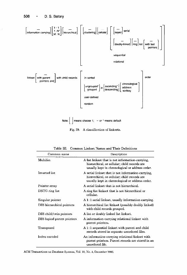
508 l D. S. Batory
information carrying] [i : i] [ hierihica j
linkset -
with parent 1 wth child records pointers and
L
[clustering] [ ceGarj
in sorted
- L 1 keyed serial
sequential
relational -I
user-defined
random
Note: [I means choose 1; - or * means default
Fig. 39. A classification of linksets.
Table III. Common Linkset Names and Their Definitions
Common name Description
Multilist
Inverted list
Pointer array
DBTG ring list
Singular pointer
IMS hierarchical pointers
IMS child/twin pointers
IMS logical parent pointers
Transposed
Index encoded
A list linkset that is not information-carrying, hierarchical, or cellular; child records are usually kept in chronological or address order.
A serial linkset that is not information-carrying, hierarchical, or cellular; child records are usually kept in chronological or address order.
A serial linkset that is not hierarchical.
A ring list linkset that is not hierarchical or cellular.
A 1: 1 serial linkset, usually information-carrying.
A hierarchical list linkset (possibly doubly linked) with child records grouped.
A list or doubly linked list linkset.
A information-carrying relational linkset with parent pointers.
A 1: 1 sequential linkset with parent and child records stored in separate unordered files.
An information-carrying relational linkset with parent pointers. Parent records are stored in an unordered file.
ACM Transactions on Database Systems, Vol. 10, NO. 4, December 1985.

Modeling Storage Architectures 509
enables recognized linkset implementations to be classified. This scheme is given in Figure 39. Note that not all combinations have been or can be implemented. Many of the exceptions have already been noted. Furthermore, some linksets are so common they are given special names-they are listed in Table III.
APPENDIX III. ADABAS
ADABAS is a product of Software AG, Inc. A typical ADABAS database is populated with one or more conceptual files which may be related explicitly by couplings or implicitly by join operations. A representative ADABAS data struc- ture diagram is shown in Figure 40. Couplings are represented by bidirectional links that connect two different conceptual files. ADABAS does not allow for a file to be coupled with itself, or for more than one coupling to exist between two files at any one time.16
The generic CONCEPTUAL record type supported by ADABAS consists of n fields, Fl . . . F,,, which are elementary or compound. An elementary or compound field may be scalar or repeating. Data values can have variable lengths. Generally, CONCEPTUAL records are variable length.
A coupling between records is made by sharing a common value in designated fields. Because fields may be repeating, couplings can be M:N. Figure 41.id illustrates an M:N coupling.
The internal files and links of ADABAS are derived in the following way. Each coupling is actualized by a pair of oppositely-directed internal links; both links are realized by M:N pointer arrays.i7 The pointers of each array are maintained in order of ascending addresses. Figure 41 shows the actualization of the coupling between the CONCEPTUALi and CONCEPTUALj files. Two ABSTRACT- CONCEPTUAL files and two internal links are produced in the process. An actualization of the couplings in the database of Figure 40 would produce a total of four ABSTRACT-CONCEPTUAL files and eight internal links.
The generic form of an ABSTRACT-CONCEPTUAL record is shown in Figure 42. An ABSTRACT-CONCEPTUAL record is the parent of m links L, . . . L, which were produced by the actualization of m couplings. A record consists of data fields F1 . . . F,, and m parent fields PL, . . . PL,.
ABSTRACT-CONCEPTUAL records are materialized in two steps (see Figure 43). First, fields PL, . . . PL, are individually segmented from the data fields F 1 . . . F,,. The result is m + 1 files and m links: there is an ABSTRACT-DATA file (containing only data fields), and for each parent field PLk there is an ABSTRACT-ASSOCIATORk file connected to ABSTRACT-DATA by link Ak. Ak is realized by a singular pointer.
Second, ADABAS allows scalar and repeating fields to be indexed. Field Fj is indexed by extracting it from ABSTRACT-DATA. This creates an
I6 Couplings are used in only 1-2 percent of ADABAS databases because their utility is limited to processing specialized queries and because they degrade performance significantly for update-inten- sive files 1321. Couplings are supported in the most recent release of ADABAS, but their use is not recommended. Join operations are promoted instead. I7 It is also correct to say that a coupling is actualized by a single link whose implementation is an M:N pointer array with parent pointers. This interpretation, however, forces one record type to be arbitrarily labeled as the “parent” and the other as the “child.” This results in a more complicated, but equivalent, derivation.
ACM Transactions on Database Systems, Vol. 10, No. 4, December 1985.

510 - D. S. Batory
CONCEPTUALi t COUPLlNGij
CONCEPTUALi
f CONCEPTUALi
CONCEPTUAL, CONCEPTUALk
dsd -
Fig. 40. A representative ADABAS dsd and fdd.
CONCEPTUALi r------------------, COUPLlNGij
CONCEPTUALi ------------------’
i _ ABSTRACT- *i CONCEPTUALi I
I I
Cji
Cij
_ i 1 ABSTRACT- 1 CONCEPTUALi I* I
ABSTRACT- CONCEPTUALi
rF,
fdd -
dsd -
I 1
id -
Fig. 41. Actualization of a coupling.
ABSTRACT-CONCEPTUAL
dsd fdd - -
Fig. 42. Generic ABSTRACT-CONCEPTUAL record type.
ACM Transactions on Database Systems, Vol. 10, No. 4, December 1985.
fdd -

Modeling Storage Architectures
ABSTRACT-CONCEPTUAL
511
ABSTRACT- DATA
I I
I
( ti bACTm q ABSTRACT- INDEXi ASSOClATO& I
I I I
_-------------___----------~~~~~~~~~~~~~~~~~~~~~~~~~---
ABSTRACT-DATA
ABSTRACT-
ABSTRACT-INDEXj
fdd -
To another ABSTRACT-
Yl V*
CONCEPTUAL file
id -
Fig. 43. Segmentation and extraction of ABSTRACT-CONCEPTUAL records.
ABSTRACT-INDEXj file. Link 4, which connects ABSTRACT-INDEXj to ABSTRACT-DATA, is realized by an MN inverted list (i.e., an MN pointer array). The pointers of each inverted list are maintained in order of ascending addresses. All fields are indexed in this manner.
Note that if a CONCEPTUAL file was uncoupled and had no indexed fields, it would be mapped directly to an .ABSTRACT-DATA record via the null transform.
Figure 43.id illustrates the relationships among three ABSTRACT-DATA records, two ABSTRACT-INDEX records, and one ABSTRACT-ASSOCIA- TOR record. Note that only the contents of a single repeating field of each ABSTRACT-DATA record is shown; this field contains value ui in one record, values u1 and v2 in a second, and value u2 in a third.
ACM Transactions on Database Systems, Vol. 10, No. 4, December 1985.

512 l D. S. Batory
ABSTRACTLINDEXj
dsd -
PRIMARY-INDEX,
fdd id - -
Fig. 44. Augmentation, encoding, and division of ABSTRACT-INDEX, records.
Pointers to ABSTRACT-DATA records are known as internal sequence num- bers (ISNs). A distinct ISN is assigned to each CONCEPTUAL record and is used to locate the record. Its realization is explained later. Internal file numbers and internal field numbers, which we collectively call IFNs, are used internally by ADABAS to reference CONCEPTUAL files and their constitutent fields. Field numbers are distinguishable from file numbers.
An ABSTRACT-INDEX, record is materialized in three steps (see Figure 44). First, a field containing the IFN of field Fj is augmented. Second, the value in field Fj is encoded by an ADABAS compression technique (see [32]). The encoded field is labeled Fj’ in Figure 44.fdd. Third, the record may be divided into one or more fragments with the IFN and Fj’ fields duplicated in each fragment. The first fragment is of type PRIMARY-INDEXj and the remaining are of type SECONDARY-INDEX,. The fragment files are connected by link Dj, which is realized by a relational linkset with link key (IFN, F:). (The conditions under which division occurs will be explained shortly.) Figure 44.id shows how an ACM Transactions on Database Systems, Vol. 10, No. 4, December 1985.

Modeling Storage Architectures l 513
ABSTRACT-ASSOCIATORk r-------------------------------
i
PRIMARY-ASSOCIATORk
Ek
v
I SECONDARY-ASSOCIATORk
I
PRIMARY-ASSOCIATORk
pLq-q-q pq-&
1 ... 20 SECONDARY-ASSOCIATORk
fdd -
21 ... 73
id -
w 74 ... 100
Fig. 45. Augmentation and division of ABSTRACT-ASSOCIATOR,+ records.
ABSTRACT-INDEXj record with an inverted list of 100 pointers might be divided into three fragments. (ui is an encoded data value and ifn( j) is the IFN for field J’j). PRIMARY-INDEX, and SECONDARY-INDEXj are internal files.
An ABSTRACT-ASSOCIATORh record is materialized in a similar manner (see Figure 45). First, a field containing the IFN of the child file of link Lk is augmented. Second, the record is divided into one or more fragments with the IFN and PAk fields duplicated in each fragment. The first fragment is of type PRIMARY-ASSOCIATORk and the remaining are of type SECONDARY- ASSOCIATORk. The fragment files are connected by link Ek, which is imple- mented by a relational linkset with link key (IFN, PAk). Figure 45.id shows how an ABSTRACT-ASSOCIATORk record with a pointer array of 100 pointers might be divided into three fragments. PRIMARY-ASSOCIATORk and SECONDARY-ASSOCIATORk are internal files.
ADABAS forces records of all PRIMARY-INDEX, SECONDARY-INDEX, PRIMARY -ASSOCIATOR, and SECONDARY -ASSOCIATOR types to have a similar format so that they can all be organized by a single file structure rather than having a separate file structure for each type. The file structure used is a
ACM Transactions on Database Systems, Vol. 10, No. 4, December 1985.
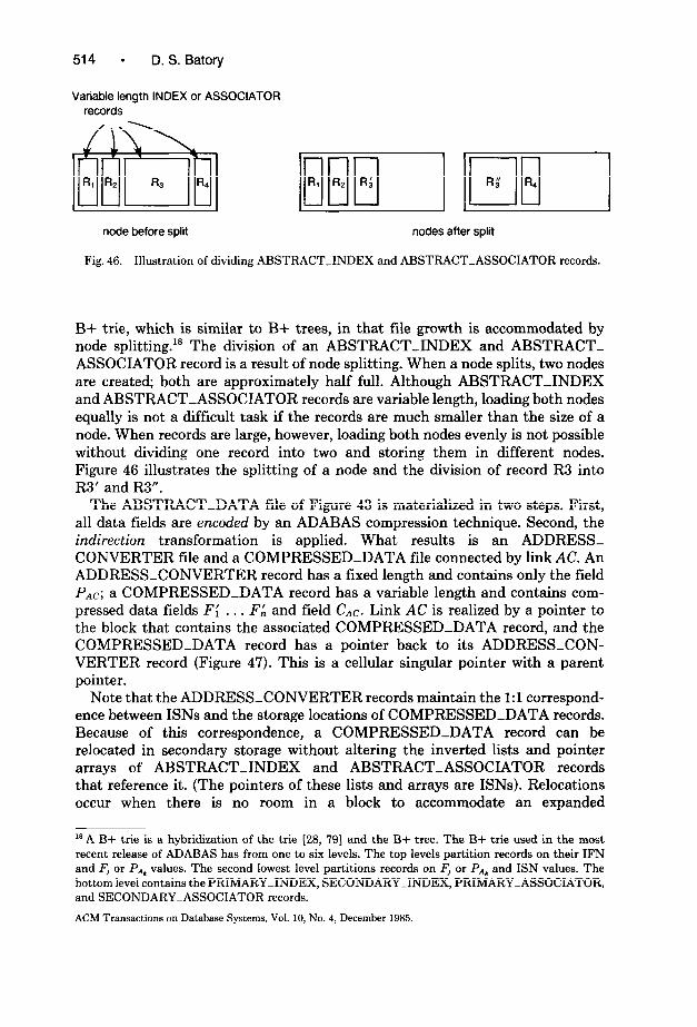
514 ’ D. S. Batory
Variable length INDEX or ASSOCIATOR records
node before split nodes after split
Fig. 46. Illustration of dividing ABSTRACT-INDEX and ABSTRACT-ASSOCIATOR records.
B+ trie, which is similar to B+ trees, in that file growth is accommodated by node splitting.” The division of an ABSTRACT-INDEX and ABSTRACT- ASSOCIATOR record is a result of node splitting. When a node splits, two nodes are created; both are approximately half full. Although ABSTRACT-INDEX and ABSTRACT-ASSOCIATOR records are variable length, loading both nodes equally is not a difficult task if the records are much smaller than the size of a node. When records are large, however, loading both nodes evenly is not possible without dividing one record into two and storing them in different nodes. Figure 46 illustrates the splitting of a node and the division of record R3 into R3’ and R3”.
The ABSTRACT-DATA file of Figure 43 is materialized in two steps. First, all data fields are encoded by an ADABAS compression technique. Second, the indirection transformation is applied. What results is an ADDRESS- CONVERTER file and a COMPRESSED-DATA file connected by link AC. An ADDRESS-CONVERTER record has a fixed length and contains only the field PAc; a COMPRESSED-DATA record has a variable length and contains com- pressed data fields Fi . . . FA and field CAc. Link AC is realized by a pointer to the block that contains the associated COMPRESSED-DATA record, and the COMPRESSED-DATA record has a pointer back to its ADDRESS-CON- VERTER record (Figure 47). This is a cellular singular pointer with a parent pointer.
Note that the ADDRESS-CONVERTER records maintain the 1:l correspond- ence between ISNs and the storage locations of COMPRESSED-DATA records. Because of this correspondence, a COMPRESSED-DATA record can be relocated in secondary storage without altering the inverted lists and pointer arrays of ABSTRACT-INDEX and ABSTRACT-ASSOCIATOR records that reference it. (The pointers of these lists and arrays are ISNs). Relocations occur when there is no room in a block to accommodate an expanded
‘* A B+ trie is a hybridization of the trie [28, 791 and the B+ tree. The B+ trie used in the most recent release of ADABAS has from one to six levels. The top levels partition records on their IFN and Fj or Pah values. The second lowest level partitions records on Fj or Pa* and ISN values. The bottom level contains the PRIMARY-INDEX, SECONDARY-INDEX, PRIMARY-ASSOCIATOR, and SECONDARY-ASSOCIATOR records.
ACM Transactions on Database Systems, Vol. 10, No. 4, December 1985.

Modeling Storage Architectures l 515
ABSTRACT-DATA
CONVERTER
dsd -
ADDRESS-CONVERTER
I PAC
COMPRESSED-DATA P
&I v; . . . VA
fdd id - -
Fig. 47. Segmentation and encoding of ABSTRACT-DATA records.
COMPRESSED-DATA record. Expansions happen when a CONCEPTUAL record is modified, such as adding a new value to a repeating field.
The internal files of ADABAS are PRIMARY-INDEX,, SECONDARY- INDEX,, PRIMARY-ASSOCIATORk, SECONDARY-ASSOCIATORh, COMPRESSED-DATA, and ADDRESS-CONVERTER. Every CONCEP- TUAL file is materialized by a collection of these files and each collection is organized by a separate group of file structures. For each CONCEPTUAL file, all record occurrences of all PRIMARY-INDEXj, SECONDARY-INDEX,, PRI- MARY-ASSOCIATORk, and SECONDARY-ASSOCIATORk files are organ- ized by a single B+ trie (see [32, 501 and footnote 18 of this Appendix). The ADDRESS-CONVERTER file is organized by an unordered file structure and the COMPRESSED-DATA file is organized by a heap. An ISN is the relative key of an ADDRESS-CONVERTER record.
ADABAS places all B+ tries and ADDRESS-CONVERTER file structures that belong to a single database in an area of secondary storage called the “associator.” (This is not to be confused with the ASSOCIATOR record types.) The COMPRESSED-DATA files of the database are placed in another called “data storage.” Separate “associator” and “data storage” areas exist for different databases.
Figure 48 summarizes the storage architecture of ADABAS. Source materials are [32, 50, 71, 721 and [87].
APPENDIX IV. SYSTEM 2000
SYSTEM 2000 is a product of MRI Systems Corporation (now Intel). SYSTEM 2000 organizes conceptual files according to a hierarchical data model. A database is viewed as a collection of disjoint trees that have record occurrences as vertices. Each tree is referred to as a database tree and consists of one root record and all
ACM Transactions on Database Systems, Vol. 10, No. 4, December 1985.

(4
516 - D. S. Batory
CONCEPTUAL
ABSTRACT-CONCEPTUAL
ABSTRACT-DATA r-------------------------------
COMPRESSED-DATA
c COUPLING, COUPLING2
Abstract File Elementary Transformations
CONCEPTUAL Actuakzation ABSTRACT-CONCEPTUAL Segmentation and extracton ABSTRACT-INDEX, (for a,, ,) Augmentation. encoding, and division ABSTRACT-ASSOCIATORI (for all k) Augmentation and division ABSTRACT-DATA Encodina and indwction
(b) (b)
Simple File Simple File lmpkmentaton lmpkmentaton
INDX-SF INDX-SF a+ vie a+ vie ADDR-CNVTR-SF ADDR-CNVTR-SF Unordered Unordered DATA-SF DATA-SF HeaD HCSP
(4 (4
* COUPLING,
internal F,le Simok File
PRIMARYWNDEX, (for all ,) INDX-SF SECONDARY-INDEX, (for all J) INDX-SF PRIMARY-ASSOCIATOR,, (for all k) INDX-SF SECONDARY-ASSOCIATOR,, (for all k) INDX-SF ADDRESS-CONVERTER ADDR-CNVTR-SF COMPRESSED-DATA DATA-SF
63
L,nk Linkset
I, (fin all j) N : M pointer array with child records in ascending physical address order
L, (for all m) N: M pointer array with child records I” ascending physical address order
A,, (for all k) Singular panter AC Cellular singular pointer with parent
potnter D, (for all ,) R&tonal lknkset with child records in
sortkey order E* (for all k) Relational links.3 with child records m
swtkev order
63
Fig. 48. The storage architecture of ADABAS.
ACM Transactions on Database Systems, Vol. 10, No. 4, December 1985.

Modeling Storage Architectures l 517
dSd fdd - -
Fig. 49. A representative SYSTEM 2000 dsd and fdd.
of its dependent records. All database trees are instances of a hierarchical definition tree which specifies the hierarchical relationships among conceptual files.lg A definition tree allows the parent, children, ancestors, and descendents of a record to be identified in a natural way. A representative SYSTEM 2000 definition tree is shown in Figure 49.
The generic CONCEPTUAL record type supported by SYSTEM 2000 consists of n data fields, Fl . . . F,,, which are elementary and scalar. Nonnumeric data values may have variable lengths; numeric values have fixed lengths. Generally, CONCEPTUAL records are variable-length.
The first step in the materialization of a hierarchical definition tree is to transform CONCEPTUAL records into ABSTRACT-CONCEPTUAL records by specifying the implementation of the links in the hierarchical definition tree. ABSTRACT-CONCEPTUAL records, it turns out, are fairly easy to understand, but their derivation is rather complicated. To make the derivation compre- hendible, we first describe an ABSTRACT-CONCEPTUAL record.
An ABSTRACT-CONCEPTUAL record differs from its CONCEPTUAL record counterpart by the addition of three fields (Fig. 49.ffd and Fig. 5l.fdd). One field, labeled IFN, identifies the CONCEPTUAL file. A second, labeled PO, is a parent field which contains a pointer to the first child record of a link D occurrence. A third, labeled CA, is a child field which contains a parent pointer and a pointer to the next child of a link A occurrence. These fields are introduced as a result of the following four step derivation (see Figure 50).
(1) SYSTEM 2000 distinguishes different CONCEPTUAL files by assigning them distinct internal file numbers (IFNs). Each CONCEPTUAL record is augmented with a field containing its respective IFN.
(2) The link between a parent file and all of its immediate child files in a hierarchical definition tree is realized by a single linkset where the roles of parent and child are preserved. The linkset is a list with parent pointers. Child records
” Terms such as record type, database tree, and hierarchical definition tree are taken from Tsichritzis and Lochovsky [80]. Different releases of SYSTEM 2000 have used different sets of terminology.
ACM Transactions on Database Systems, Vol. 10, No. 4, December 1985.

518 l D. S. Batoty
CONCEPTUALi
Li
4 4
ABSTRACT- ABSTRACT- CONCEPTUALi CONCEPTUALk
I
CONCEPTUAL,,
ABSTRACT-CONCEPTUAL,
I,,)1
Last Pointer
r I \ \
j i k k I
Note: r q is a record of type ABSTRACT-CONCEPTUAL,
fdd - fi
Fig. 50. Augmentation and collection of CONCEPTUAL records.
are arranged in user-defined order. Figure 50.id illustrates a possible arrangement. All links in a hierarchical definition tree are realized in this manner.
Observe that assigning list implementations to each conceptual link introduces a parent field in the root record type, a child field in leaf record types, and both ACM Transactions on Database Systems, Vol. 10, No. 4, December 1985.

Modeling Storage Architectures
Note: All pointers reference other ABSTRACT-CONCEPTUAL records.
dsd - fdd - id -
Fig. 51. Generic ABSTRACT-CONCEPTUAL record type.
parent and child fields in the intermediate record types of a hierarchical definition tree. In order for all records of all ABSTRACT-CONCEPTUAL files to have both parent and child fields, some null pointer fields must be introduced. This is done in the remaining two steps.
(3) So that all instances of the root record type can be assessed efficiently, root records are collected together by link ROOT. ROOT is implemented as a list linkset (with precisely one occurrence) with parent pointers and a pointer to the last root record.” (Note that a parent pointer to the system l record is’indistin- guishable from a null pointer.) Root records are arranged in a user-defined order.
(4) A field containing a single null pointer is augmented to each leaf record type of a hierarchical definition tree. This field is indistinguishable from a parent field (labeled PO in Figure 5l.fdd) of a list linkset where there are no child records. These null pointers are shown in the occurrence of record types AB- STRACT-CONCEPTUALj and ABSTRACT-CONCEPTUALh in Figure 5O.id.
The generic form of an ABSTRACT-CONCEPTUAL record is shown in Figure 51. An ABSTRACT-CONCEPTUAL record is a child of link A (A for ancestor) and is the parent of link D (D for descendent). (Note that a specific instance of A is ROOT.) An ABSTRACT-CONCEPTUAL record consists of an IFN field, a parent field PO, a child field CA, and n data fields Fl . . . F,,.
An ABSTRACT-CONCEPTUAL record is materialized in the following way (see Figure 52). SYSTEM 2000 creates an index for all data fields, unless told otherwise in the schema definition. Field Fj is indexed by extracting it from ABSTRACT-CONCEPTUAL records, forming an ABSTRACT-INDEXj file. Link 4, which connects ABSTRACT-INDEX, to ABSTRACT-DATA, is imple- mented by a 1:N inverted list. Pointers of an inverted list are in chronological order. Other fields are indexed in an identical manner.
Note that if an ABSTRACT-CONCEPTUAL file had no indexed fields, it would be mapped directly to the ABSTRACT-DATA file via the null transfor- mation.
” SYSTEM 2000 actually stores the pointer to the last root record in the parent pointer slot of the first root record of the ROOT list. (Normally, this slot would otherwise be occupied by a null pointer.) A slightly more efficient implementation would store the last pointer in the system l record as shown in Figure 50.id.
ACM Transactions on Database Systems, Vol. 10, No. 4, December 1985.

520 - D. S. Batory
ABSTRACT-CONCEPTUAL ,________----__---_----~--.
1 ABSTRACT- 1
i
I__---------_--~~~~~~~~~-~
dsd -
ABSTRACT-DATA
i ABSTRACT-INDEX,
\ / fi
fdd id - -
Fig. 52. Extraction of ABSTRACT-CONCEPTUAL data fields.
The data fields F, . . . F,, and inverted list fields PI, of ABSTRACT-INDEXj and ABSTRACT-DATA records are mapped to their internal counterparts by a conditional application of elementary transformations. The conditions under which a transformation is applied depends on the length of the data value and the length of the field in which it is to be stored. These mappings and their transformation models are explained in the following paragraphs.
When a CONCEPTUAL record type is defined, each field Fj is given a nominal length lenj. If the length of a data value to be stored in Fj is shorter than lenj bytes, the data value is stored left-justified with blank padding. If it is longer, the first lenj - b bytes are stored in the field and the remaining bytes are stored a single EFTj (extended field table) record. A pointer of length b bytes connects the “overflowed” field to the EFTj record. All data fields are represented in this mariner....
” As numeric data values are fixed-length, division actually occurs only for nonnumeric data values. To distinguish between data values that are divided from those that are not, SYSTEM 2000 restricts the set of characters that can appear in a nonnumeric field. This enables a bit flag to be encoded within a character sequence to make the distinction.
ACM Transactions on Database Systems, Vol. 10, No. 4, December 1985.

Modeling Storage Architectures l 521
This materialization is modeled by two transformations: the null transforma- tion describes the case where a data value has a length less than or equal to lenj bytes. The diuision transformation captures the other case where a data value is divided into two fragments: the first fragment is stored with the original record, the second is stored as an EFTj record. Both records are connected by a singular pointer linkset. This materialization is referred to as the overflow transformation.
Each ABSTRACT-INDEXj record contains an inverted list field PIj. SYSTEM 2000 stores the contents of this field in one of two ways. If there is precisely one pointer in PI,, the field is not modified. (This is modeled by the null transfor- mation.) If there are two or more pointers, PI, is divided into variable-length fragments called MOTj (multiple occurrences tablej) records. Link Mj, which connects the index record to its MOT records, is realized as a multilist with last child pointers. MOTj records are linked in chronological order. This materiali- zation is referred to as the inverted list transformation.
An ABSTRACT-INDEXj record is materialized by applying the overflow transformation to field Fj and the inverted list transformation to field PIj. A DVTj (distinct value tablej) record is produced as a result. Also, link vj and an EFTj records are produced if field Fj is divided, and link Mj and MOTj records are produced if field PI, is divided. Thus an ABSTRACT-INDEX file is mapped to one or more (internal) files in one of four different ways. Figure 53 illustrates each of these ways.” Note that the PMj and PIj fields in Figure 53.fdd occur in mutually exclusive situations and that both have the same length. Thus, for a given j, all records of the DVT,!” . . DVTY’ files share the same fixed length. This enables the records of all four DVTI” types to be organized by a single file structure.
The ABSTRACT-DATA file of Figure 52 is materialized by segmenting the IFN, PO, CA fields from the data fields FI . . . F,,. This produces an HT (hierar- chical table) file and an ABSTRACT-DT file connected by link H. His realized as a singular pointer (see Figure 54).
An ABSTRACT-DT record is materialized by applying the overflow transfor- mation to each of its data fields. The resulting data record is referred to as a DT (data table) record; link Ej connects it with at most one EFTj record for each data field Fj. Figure 55.id illustrates a DT record with three data fields that have overflowed. Owing to the nature of the overflow transformation, DT records have a fixed length (which equals the sum of the nominal field lengths of the corresponding fields of the CONCEPTUAL record type). DT records of different CONCEPTUAL record types will, of course, have different lengths. EFTj records have variable lengths.
It is worth noting that if a data value overflows its nominal field length and that it occurs multiple times in a CONCEPTUAL file, there will be an EFTj
” SYSTEM 2000 actually stores the pointer to the last MOT, record of an Mj link occurrence in the first MOT, record. A slightly more efficient implementation would store the last pointer in the DVTj as shown in Figure 53.id.
MOT records are variable-length. When a database is first loaded, all pointers of an inverted list are placed in a single MOT record. Subsequent pointer insertions are placed in new MOT records. The length of a new MOT record is a function of the length of the first MOT record.
ACM Transactions on Database Systems, Vol. 10, No. 4, December 1985.

ABSTRACT-INDEXj
1 DVTj”’ 1
or
ti
DVTi’”
cl MOTj
or
dsd
DVTp”
Pointer to ABSTRACT-DATA Record
DVTj’2’
-q-py
EFTj
DVTf3’
p-j-q
MOTj
q-j-q
DVTj”’
EFTi
(
MOTj
p-j-q
‘Vj
:,
F]
Pointer to ABSTRACT-DATA Record
Pointers to ABSTRACT-DATA Records
Pointers to ABSTRACT-DATA Records
fdd id - -
Fig. 53. Overflow and inverted list transformation of ABSTRACT-INDEX,.

Modeling Storage Architectures l 523
ABSTRACT-DATA Parent Pointer _______----__---_------~~~
x 1 z First Child?:
I I
dsd - fdd - id -
Fig. 54. Segmentation of ABSTRACT-DATA records.
ABSTRACT-DT ,___-------__-------- ------I I I I I
dsd -
fdd id - -
Fig. 55. Overflow transformation of fields of ABSTRACT-DT records.
ACM Transactions on Database Systems, Vol. 10, No. 4, December 1985.

524 l D. S. Batory
1 A
CONCEPTUAI
(a)
I_ ------------ I:~z--.lz--------------~-----~~- --------------------------------------- ABSTRACT-CONCEPTUAL
__----___--_____________________________-------------------------------------------
ABSTRACT-DATA
HT 7 H ABSTRACT-DT
I~___----__---__-----------~~~~~~~~i
Abstract File Elementary Transformations Internal File Simple File
CONCEPTUAL Augmentation and collection ABSTRACT-CONCEPTUAL Extraction ABSTRACT-INDEX, (for all j) Overflow and inverted list ABSTRACTDATA Segmentation ABSTRACT-DT Overflow
(W
Simple File
HT-SF DT-SF EFT-SF
Implementation
Unordered Unordered Unordered
Link
H E, (for all i) V, (for all I)
HT HT-SF DT DT-SF EFT, (for all J) EFT-SF DVTI(‘) (for all i, J) DVT-SF, MOT, (for all j) MOT-SF
(c)
Linkset
Singular pointer Singular pointer Sinaular oointer
DVT-SF, (for all j) B+ tree bi, jfor all’j) 1 : i list with last pointer MOT-SF Unordered I, (for all i) 1 : N inverted list
(4 D 1 : N list with parent pointers A 1 : N list with parent pointers
(and last pointer if CONCEPTUAL file is root file of hierarchy)
(4
Fig. 56. The storage architecture of SYSTEM 2000.
ACM Transactions on Database Systems, Vol. 10, No. 4, December 1985.

Modeling Storage Architectures l 525
record for each of its occurrences if the data field itself is not indexed. SYSTEM 2000 eliminates duplicate EFTj records for data fields that are indexed.23
The internal files of SYSTEM 2000 are DVTI”, MOT,, HT, DT, and EFT;. For each j, files DVT;” through DVTY’ are stored in a single B+ tree. (Thus, for each value of j, there will be a distinct B+ tree). All MOTj files are stored in a single unordered file. The HT and DT files are stored in separate unordered tiles, and all EFTj files are stored in a single unordered file.24
Figure 56 summarizes the storage architecture of SYSTEM 2000. Source materials are [16, 27, 501 and [80].
ACKNOWLEDGMENTS
I gratefully acknowledge the encouragement, support, and ideas I received from the following people: Ignacio Casas at the University of Toronto; Jim Desper at Infodata Systems, Inc.; John McCarthy at Lawrence Berkeley Laboratories; Alex Buchmann at IIMAS; Alan Wolfson at Software AG; Paul Butter-worth at Relational Technology; Barbara Foster at Intel; Stan Su, Sham Navathe, and Jim Parkes at the University of Florida, and Tim Wise at the University of Texas. I thank the referees for suggesting several important improvements to the paper. I also thank Arie Shoshani (Lawrence Berkeley Laboratories) for his considerable assistance and insight in improving the clarity of this paper.
REFERENCES
1. AGHILI, H., AND SEVERANCE, D. G. A practical guide to the design of differential files for recovery of on-line databases. ACM Trans. Database Syst. 7,4 (Dec. 1982), 540-565.
2. ALSBERG, P. A. Space and time savings through large database compression and dynamic restructuring. Proc. IEEE 63, 8 (Aug. 1975), 1114-1122.
3. BAROODY, A. J., AND DEWITT, D. J. An object-oriented approach to database system imple- mentation. ACM Trans. Database Syst. 6, 4 (Dec. 1982), 576-601.
4. BATORY, D. S. On searching transposed files. ACM Trans. Database Syst., 4, 4 (Dec. 1979), 531-544.
5. BATORY, D. S. Optimal file designs and reorganization points. ACM Trans. Database Syst. 7, 1 (Mar. 1982), 60-81.
6. BATORY, D. S. Conceptual-to-internal mappings in commercial database systems. ACM PODS 1984,70-78.
7. BATORY, D. S. Unpublished manuscript, 1984. 8. BATORY, D. S. Progress toward automating the development of database system software. Query
Processing in Database Systems, W. Kim, D. Reiner, and D. S. Batory, Eds., Springer Verlag, New York, 1985.
9. BATORY, D. S. GENESIS-An internal database compiler: Status report. In preparation. 10. BATORY, D. S., AND GOTLIEB, C. C. A unifying model of physical databases. ACM Trans.
Database Syst. 7,4 (Dec. 1982), 509-539.
*3 Note that our model does not capture this aspect of EFT records; we model all fields by duplicating EFT records. It is believed that this problem can be rectified by casting the TM in terms of an object- oriented model. This would allow the contents of a data field to be treated as an object. When a data field is duplicated (as in extraction with duplication), the object that it contains is not actually duplicated, but rather a reference to the object is created. When the object is stored, all references will point the single object instance. *’ A SYSTEM 2000 database has another tile called the DEFIN file. It contains metadata, such as the root nodes of all simple files and the system l record.
ACM Transactions on Database Systems, Vol. 10, No. 4, December 1985.

526 - D. S. Batory
11. BATORY, D. S., AND KIM, W. Modeling concepts for VLSI CAD objects. ACM Trans. Database Syst. 10,3 (Sept. 1985), 322-346.
12. BERELIAN, E., AND IRANI, K. B. Evaluation and optimization. In Proceedings VLDB 1977, 545-555.
13. BOHL, M. Introduction to IBM Direct Access Storage Devices. SRA, 1981. 14. BURNETT, R. A. A self-describing data file structure for large data sets. In Computer Science
and Statistics: Proceedings of the 13th Symposium of the Interface, Springer Verlag, New York, 1981,359-362.
15. CASAS, I. R. Analytic modeling of database systems: The design of a System 2000 performance predictor. M.Sc. thesis, Dept. of Computer Science, Univ. of Toronto, 1981.
16. CASAS, I. R. Technical discussion, Univ. of Toronto, 1982. 17. CASAS, I. R. Performance prediction of database systems. Ph.D. thesis, Dept. of Computer
Science, Univ. of Toronto, 1985. 18. CERI, S., AND PELAGATTI, G. Distributed Databases: Principles and Systems, McGraw-Hill, New
York, 1984. 19. CHEN, P. P. S. The entity-relationship model-Toward a unified view of data. ACM Trans.
Database Syst. 1, 1 (Mar. 1976), 9-36. 20. CINCOM SYSTEMS, INC. TOTAL PDP-11 Programmers Reference Manual. Cincinnati, Ohio,
1979. 21. COMER, D. The ubiquitous B-tree. ACM Comput. Surv. 11, 2 (June 1979), 121-138. 22. CULLINANE DATABASE SYSTEMS, INC. IDMS System Overview, Westwood, Mass., 1981. 23. DAS, K. S., AND TEOREY, T. J. Detailed specifications for the file design analyzer. Tech. Rep.
87, Systems Engineering Lab., Univ. of Michigan, Ann Arbor, 1975. 24. DATE, C. J. An Introduction to Database Systems, 3rd ed., Addison-Wesley, Reading, Mass.,
1982. 25. DESPER, J. Technical discussion, Infodata Systems, Inc., 1983. 26. FAGIN, R., NIEVERGELT, J., PIPPENGER, N., AND STRONG, H. R. Extendible hashing-A fast
access method for dynamic files. ACM Trans. Database Syst. 4, 3 (Sept. 1979), 315-344. 27. FOSTER, B. Technical discussion, Intel Corp., 1984. 28. FREDKIN, E. Trie memory. Commun ACM 3 (1960), 490-500. 29. FRY, J. P., ET AL. Stored-data description and data translation: A model and language. Znf
Syst. 2 (1977), 95-148. 30. GAMBINO, T. J., AND GERRITSEN, R. A database design decision support system. In Proceedings
of the ACM Conference on Very Large Data Bases (1977), ACM, New York, 534-544. 31. GARZA, J. F. Design and implementation of JUPITER: A general file management system.
M.Sc. thesis, Dept. of Computer Science, Univ. of Texas at Austin, 1985. 32. GESELLSHAFT FUER MATHEMATIK UND DATENVERARBEITUNG. ADABAS: Database Systems
Investigation Report, vol. 2, part 1, Institute fuer Informationssysteme, Bonn, 1976. 33. GOTLIEB, C. C. Some large questions about very large databases. In Proceedings of the ACM
Conference on Very Large Data Bases (1981), ACM, New York, 3-7. 34. GRAY, J. N. Practical problems in database management-A position paper. ACM SZGMOD,
1983, 3. 35. GUTTAG, J. Abstract data types and the development of data structures. Commun. ACM 20, 6
(June 1977), 396-404. 36. GUTTMAN, A., AND STONEBRAKER, M. Using a relational database management system for
computer-aided design data. Electronics Research Laboratory, UCB/ERL M82/37, Univ. of California, Berkeley, 1982.
37. HAMMER, M. Data abstractions for databases. In Proceedings of the Conference on Data: Abstractions, Definitions, and Structure. SIGPLAN Not. 11 (1976), 58-59.
38. HASKIN, R., AND LORIE, R. On extending the functions of a relational database system. ACM SZGMOD (1982), 207-212.
39. HELD, G. D., AND STONEBRAKER, M. R. B-trees reexamined. Commun. ACM 21,2 (Feb. 1979), 139-142.
40. HOFFER, J. A. A clustering approach to the generation of subfiles for the design of a computer database. Ph.D. dissertation, Cornell Univ., Ithaca, N.Y., 1975.
41. HSIAO, D., AND HARARY, F. A formal system for information retrieval from files. Commun. ACM 13, 2 (Feb. 1970), 67-73.
ACM Transactions on Database Systems, Vol. 10, No. 4, December 1985.
Modeling Storage Architectures l 527
42. HSIAO, D. ED. Advanced Database Machine Architecture. Prentice-Hall, Englewood Cliffs, N.J., 1983.
43. HUFFMAN, D. A. A method for the construction of minimal redundancy codes. In Proceedings IRE 40 (Sept. 1952), 1098-1101.
44. IBM Corp. IMS/VS Version I: Database Administration Guide. San Jose, Calif., 1981. 45. INFODATA SYSTEMS, INC. INQUIRE Basic Training Course. Pittsford, N.Y., 1979. 46. INFODATA SYSTEMS, INC. INQUIRE Database Design and Loading Manual. Pittsford, N.Y.
1979. 47. KING, R. P., KORTH, H. F., AND WILLNER, B. E. Design of a document filing and retrieval
service. ACM SIGMOD, 1983. (Business and Office Databases). 48 KNUTH, D. E. The Art of Computer Programming, vol. 3: Sorting and Searching, Addison-
Wesley, Reading, Mass., 1983. 49. KORNATOWSKI, J. Z. The MRS User’s Manual. Computer Systems Research Group, Univ. of
Toronto, 1979. 50. KROENKE, D. Database Processing, S.R.A. Inc., Chicago, 1977. 51. LARSON, P. Dynamic hashing. BIT 28 (1978), 184-201. 52. LEMPEL, A. Cryptology in transition. ACM Comput. Surv. 21, 4 (Dec. 1979), 285-305. 53. LORIE, R., ET AL. User interface and access techniques for engineering databases. To appear in
Query Processing in Database Systems, Springer Verlag, New York, 1984 (see [9]). 54. MARCH, S. T. Techniques for structuring database records. ACM Comput. Surv. 15, 1 (Mar.
1983), 45-80. 55. MARCH, S. T., AND SEVERANCE, D. G. The determination of efficient record segmentations and
blocking factors for shared data files. ACM Trans. Database Syst. 2, 3 (Sept. 1977), 279-296. 56. MARCH, S. T., SEVERANCE, D. G., AND WILENS, M. Frame memory: A storage architecture to
support rapid design and implementation of efficient databases. ACM Trans. Database Syst. 6,3 (Sept. 1981), 441-463.
57. MAXWELL, W. L., AND SEVERANCE, D. G. Comparison of alternatives in an information system. In Proceedings Wharton Conference on Research on Computers in Organizations (Oct. 1973), Univ. of Pennsylvania, Philadelphia, 1-16.
58. MITOMA, M. F., AND IRANI, K. B. Automatic database schema design and optimization. In Proceedings of the ACM Conference on Very Large Data Bases (1975), 286-321.
59. NAKAMURA, T., AND MIZOGUCHI, T. An analysis of storage utilization factor in block split data structuring scheme. In Proceedings of the ACM Conference on Very Large Data Bases (1978), 489-495.
60. NATIONAL BUREAU OF STANDARDS Federal Information Processing Standards, Publ. 46, 1977. 61. NDX RETRIEVAL SYSTEMS, INC. CREATABASE Performance Manual. Houston, Tex., 1981. 62. NIEVERGELT, J., HINTERBERGER, H., AND SEVCIK, K. C. The grid file: An adaptable, symmetric
multikey file structure. ACM Trans. Database Syst. 9, 1 (Mar. 1984), 38-71. 63. ONG, J., Focc, D., AND STONEBRAKER, M. Implementation of data abstraction in the relational
database system INGRES. ACM SZGMOD Rec. 14, 1 (Mar. 1984), 1-14. 64. RITCHIE, D. M., AND THOMPSON, F. The UNIX time-sharing system. Commun. ACM 17, 7
(July 1974), 365-375. 65. ROWE, L. A., AND SHOENS, K. A. Data abstractions, view, andupdates in RIGEL. In Proceedings
ACM SIGMOD (1979), 71-81. 66. SCHOLL, M. New file organizations based on dynamic hashing. ACM Trans. Database Syst. 6,
1 (Mar. 1981), 194-211. 67. SENKO, M. E., ALTMAN, E. B., ASTRAHAN, M. M., AND FEHDER, P. L. Data structures and
accessing in database systems. IBM Syst. J. 12, 1 (1973), 30-93. 68. SEVERANCE, D. G. Some generalized modeling structures for use in design of file organizations.
Ph.D. thesis, Univ. of Michigan, Ann Arbor, 1972. 69. SEVERANCE, D. G., AND LOHMAN, G. M. Differential files: Their application to the maintenance
of large databases. ACM Trans. Database Syst. I, 3 (Sept. 1976), 256-267. 70. SHIPMAN, D. The functional data model and the data language DAPLEX. ACM Trans. Database
Syst. 2,2 (June 1977), 105-133. 71. SOFTWARE AG OF NORTH AMERICA, INC. ADABAS: Introduction. Reston, Va., 1977. 72. SOFTWARE AG OF NORTH AMERICA, INC. ADABAS: Effectiue Data Base Management for the
Corporate Environment. Reston, Va., 1980.
ACM Transactions on Database Systems, Vol. 10, No. 4, December 1985.

528 l D. S. Batoty
73. SPERRY-UNIVAC DMS-1100 Schema Definition: Data Administrator Reference. 1975. 74. STANFORD UNIV. Design of SPIRES: Vols. I and II. Center for Information Processing, Stanford
Univ., 1973. 75. STATISTICS CANADA RAPID Internals Manual. Ottawa, Ont., 1981. 76. STONEBRAKER, M., WONG, E., KREPS, P., AND HELD, G. The design and implementation of
INGRES. ACM Trans. Database Syst. 1,3 (Sept. 1976), 189-222. 77. STONEBRAKER, M., RUBENSTEIN, B., AND GUTTMAN, A. Application of abstract data types and
abstract indices to CAD data bases. In Proceedings 1983 ACM Engineering Design Applications, ACM, New York, 107-114.
78. SVENSSON, P. On search performance for conjunctive queries in compressed, fully transposed ordered files. In Proceedings of the ACM Conference on Very Large Data Bases (1979), 155-163.
79. TEOREY, T. J., AND FRY, J. P. Design of Database Structures. Prentice-Hall, Englewood Cliffs, N.J., 1982.
80. TSICHRITZIS, D. C., AND LOCHOVSKY, F. Data Base Management Systems. Academic Press, New York, 1977.
81. TSICHRITZIS, D. C., AND KLUG, A., EDS. The ANSI/XB/SPARC DBMS framework report of the Study Group on Database Management Systems. Inf. Syst. 3, (1978), 173-191.
82. TSICHRITZIS, D., AND CHRISTODOULAKIS, S. Message files. ACM Trans. Office Inf. Syst. 1, 1 (Jan. 1983), 88-98.
83. TURNER, M. J., HAMMOND, R., AND COTTON, P. A DBMS for large statistical databases. In Proceedings of the ACM Conference on Very Large Data Bases (1979), 319-327.
84. WELLS, M. File compression using variable length encodings. Comput. J. 15, 4 (1972) 308-313. 85. WIEDERHOLD, G. Database Design, 2nd ed., McGraw-Hill, New York, 1983. 86. WISE, T. E. A technique to model and design physical database structures. M.Sc. thesis, Dept.
of Computer and Information Sciences, Univ. of Florida, 1983. 87. WOLFSON, A. Technical discussion. Software AG of North America, Inc., 1983. 88. YAO, S. B. An attribute-based model for database cost analysis. ACM Trans. Database Syst. 2,
1 (Mar. 1977), 45-67. 89. ZIV, J. AND LEMPEL, A. A universal algorithm for sequential data compression. IEEE Trans.
Inf. Theor. IT-23,3 (May 1977), 337-343.
Received June 1983; revised July 1984; accepted June 1985
ACM Transactions on Database Systems, Vol. 10, No. 4, December 1985.