modeling the load mode of transmission of a heavy truck in
TRANSCRIPT
Abstract— The safety of the vehicle, its stability and
controllability, as well as passability, attract the attention of a
large number of researchers, testers and designers and are
considered in the modern automobile industry as one of the
strategic directions that determine the complex of the most
important operational properties. In this regard, there is a
need to study the dynamics of the movement of vehicles with
the use of modeling tools. The article deals with the loading
mode of the truck transmission for the typical case of operation
- starting with a clutch release. A mathematical model of a
truck with a 4x2 wheel arrangement is implemented, which
helps to simulate the process of starting a vehicle with a clutch
release.
Index Terms— heavy truck, simulation, transmission,
loading mode.
I. INTRODUCTION
Simulation modeling of the process of vehicle movement
is becoming more widespread in the world scientific
practice. The main reason for this is the possibility of
obtaining the necessary characteristics of the developed
product without carrying out experimental measures, i.e. at
the design stage, which positively affects the overall quality
of the products and reduces its cost.
The work has been performed with the financial support of the Ministry
of education and science of the Russian Federation as a part of complex
project to create a high-tech production “Development of high-tech
production of new generation energy efficient transmissions for trucks and
buses” by agreement No. 02.G25.31.0142 d.d. December, 01, 2015
concluded between the Ministry of education and science of the Russian
Federation and Public Joint-Stock Company “KAMAZ” in cooperation
with the head executor “NIOKTR” - Federal State Autonomous
Educational Institution of Higher Education “South Ural State University
(National Research University)”.
N. Z. Maltseva is with the South Ural State University, 76 Prospekt
Lenina, Chelyabinsk, 454080, Russian Federation (cell phone:
+79821085930; e-mail: [email protected]).
V. V. Anchukov is with the South Ural State University, 76 Prospekt
Lenina, Chelyabinsk, 454080, Russian Federation (cell phone:
+79823041440; e-mail: [email protected]).
A. S. Alyukov is with the South Ural State University, 76 Prospekt
Lenina, Chelyabinsk, 454080, Russian Federation (corresponding author,
cell phone: +79000716743; e-mail: [email protected]).
Currently, there are many approaches to modeling the
dynamics of the vehicle, but not all of them are universal.
Let's consider some of them.
In [1, 2], the authors developed mathematical models of
heavy trucks. In [3] the mathematical model of bench tests
of the car is presented, which allows simulating a number of
standardized bench tests. The methods of simulation
modeling are widely developed, they have been considered
sufficiently in the following papers [4, 5, 6].
In the work of Keller A. V., Murog I. A. [7, 13] the
authors solve the scientific problem of providing the
required level of passability with the help of mathematical
modeling.
Analyzing the works discussed above, it can be concluded
that at the present time the issues related to the assessment
of the dynamics of the vehicle movement taking into
account the dynamic processes in all the main subsystems of
the vehicle (engine, transmission, suspension and wheels)
have not been fully studied. Thus, the creation of an
adequate and sufficiently detailed model of motion is a
completely logical stage in the development of the problem
of estimating the dynamics of a vehicle.
II. MATHEMATICAL MODEL DESCRIPTION
The dynamics of the movement of vehicles is a complex
process, the study of which is advisable to break down into
several main stages. It is proposed to begin with studying
dynamics when starting, and at the next stage to investigate
the dynamics of the vehicle's motion along the deformable
ground with controlled power distribution mechanisms.
To conduct research, LMS Amesim software was used
the integrated 1D modeling platform for constructing and
analyzing heterogeneous (multi-physical) intelligent systems
and predicting their interdisciplinary characteristics, in
which the components of the product are described by
analytical models representing the interaction processes of
mechanical, hydraulic, pneumatic and electrical subsystems.
To create a simulation model of the system in LMS
Amesim, large set of library components from different
physical areas is used. With the help of the software, a
model based on physical processes was created, which in
turn allowed to simulate the behavior of intelligent systems
before the creation of detailed CAD geometry. For the
correct and reliable realization of the model of the vehicle in
the Amesim, the elements necessary for creating the model
were studied and selected. From the selected elements, the
model was collected and the necessary parameters were set.
As a result, the model of a truck was fully realized, which
was fully consistent with the real object.
Modeling the Load Mode of Transmission of a
Heavy Truck in Case of Starting with a Clutch
Release
N. Maltseva, V. Anchukov, A. Alyukov
THE safety of the vehicle, its stability and controllability,
as well as passability attract the attention of a large number
of researchers, testers and designers and are considered in
the modern automobile industry as one of the strategic
directions that determine the complex of the most important
operational properties. In this regard, there is a need to study
and the dynamics of the movement of vehicle with the help
of innovative computer modeling tools.
Proceedings of the World Congress on Engineering and Computer Science 2018 Vol II WCECS 2018, October 23-25, 2018, San Francisco, USA
ISBN: 978-988-14049-0-9 ISSN: 2078-0958 (Print); ISSN: 2078-0966 (Online)
WCECS 2018
The creation of a model of a 4x2 wheeled truck begins
with the study of its transmission. The development of the
calculation model of the transmission began with the
determination of the composition of nodes and elements,
then all the parameters necessary for modeling and the
transmission scheme were compiled.
The transmission consists of the following main elements:
- engine;
- clutch;
- gear box;
- main drive of the rear axle;
- differential of the rear drive axle;
- rear driving wheels.
Consider in more detail the processes that take place inside
the machine during the start-up, as well as the main
elements of the transmission.
The torque from the engine installed in the front of the
vehicle is transmitted through the clutch onto the gearbox.
From the gearbox, the torque is transmitted through the
cardan gear to the rear drive axle, inside which the main
gear is housed, the differential and the axle of the drive
wheels. The vehicle starts to move in lower gears with a
increasing frequency from idling to the maximum speed of
the engine's crankshaft.
The clutch of the vehicle is located between the engine
and the gearbox. It is intended for a short-term detachment
of the engine from the transmission and their smooth
connection when changing gears, as well as protecting the
transmission elements from overloading and damping of
vibrations.
Clutch has two modes of operation:
1) clutch is off, i.e. engine and transmission are not
connected. At this time, the torque is not transmitted from
the engine to the gearbox, which allows to switch gears
without jerking or stalling the engine;
2) clutch is on, i.e. engine and transmission are connected.
At this time there is synchronization of the engine torque
with the gearbox, due to the friction of the flywheel.
The clutch model is a mathematical model of the
transmission of torque with the help of frictional forces of
rotating clutch parts (disks). Mass moments of inertia of
rotating parts are taken into account in the model. The
control action is a binary signal: 0 - corresponds to the
engaged clutch state, 1 - to the disabled state. In this case, it
is possible to realize intermediate states of cohesion, i.e.
incomplete on or off.
The law of increasing frictional moment in the clutch is
modeled in the corresponding block (No. 16 in Figure 1),
determined by the type and parameters of the drive and
described with sufficient accuracy by the exponential
dependence:
where k - constant characterizing the rate of engagement of
the clutch (k=3/tc), tc - time of full clutch engagement.
For the clutch of KAMAZ vehicles, the time for full
engagement is set to tc = 0.1 s [9].
The main transmission block (No. 15 in Figure 1) is a
physically oriented operator of the mechanics library of the
LMS Amesim package operating on the principle of a
reducer. The main parameter is the gear ratio, the amount of
which increases the torque and reduces the speed of rotation.
A similar operator is used to convert the torque in the
gearbox.
The differential is designed to transfer, change and
distribute the torque between the two half-axles, combined
with the wheels, and provide, if necessary, their rotation
with different angular speeds. The differential is used to
distribute the power that is to be transmitted from the engine
to the wheel.
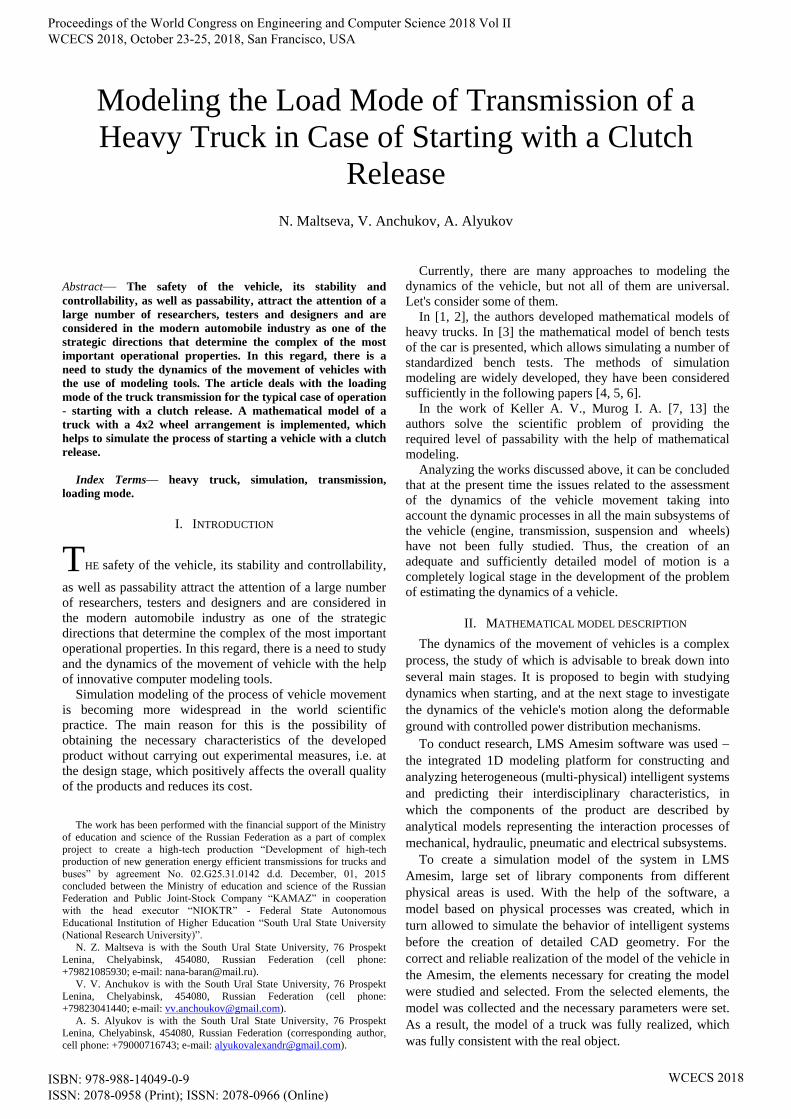
Developed mathematical model in LMS Amesim is
shown on Figure 1.
Figure 1 – Developed mathematical model in LMS Amesim
Here, 1 - external speed characteristic signal; 2 - reduced
moment of inertia of the engine; 3 - sensors that measure the
engine speed and torque; 4 - clutch; 5 - a signal of inclusion
of clutch; 6 - the inter-wheel differential; 7 - a signal of fuel
supply; 8 – engine torque; 9, 11, 13 - the elastic elements of
the transmission; 10, 14 - given moments of inertia at an
input and an output shafts of transmission; 12 - gear ratio;
15 - main gear; 16 – clutch friction moment.
After the creation of the transmission model and its
debugging, the next stage of modelingis the creation of the
chassis of the car, as a system consisting of sprung and
unsprung masses. For this purpose, the mass-inertial
characteristics of the vehicle were determined, such as the
coordinates of the center of gravity. The sketch of the
complete model is shown in Figure 2.
The car body model is a solid body with corresponding
mass-inertial characteristics, to which external influences,
determined by the driving regime, are transmitted.
In the model of spatial motion of the vehicl, a tire model
is used from the library of the LMS Amesim package. The
model uses a complex approach to describe the interaction
of the wheels with the road. The model is described with
sufficient accuracy using the formula "Pacejka 1989" [12]
and is implemented in this model, the type of pavement and
microprofile are specified by the elements "Roadmodel" and
"Adherence generator" (Figure 2).
This submodel represents the "tire-road" interaction with
vertical force and longitudinal component of the force
arising from the contact of the pneumatic tire with the road
surface, due to rolling resistance and road obstacles taken
into account. The longitudinal force depends on the vertical
load. The vertical force is calculated taking into account the
rigidity of the suspension, the wheels and the location of the
center of gravity of the body. The connections of the car's
wheels to the road's supporting surface are described by
equations that take into account only elastic sliding (the
wheels do not detach from the road).
Different road conditions are simulated with the help of
specially oriented library elements (Figure 3), which allows
Proceedings of the World Congress on Engineering and Computer Science 2018 Vol II WCECS 2018, October 23-25, 2018, San Francisco, USA
ISBN: 978-988-14049-0-9 ISSN: 2078-0958 (Print); ISSN: 2078-0966 (Online)
WCECS 2018

to set different laws for changing and distributing the
coefficient of adhesion and road micro profile. In the studied
case, the type of road surface is dry asphalt with a
coefficient of adhesion of 0.8, and the microprofile of the
road is a straight road.
Figure 2 – Coordinate frames assignment of a 6WD truck
1 - engine-transmission unit, 2 - chassis, 3 - car body, 4 - suspension
Figure 3 – Model of wheel-road interaction
1 - wheel model, 2 - model describing the type of pavement, 3 - model
describing the microprofile of the pavement
For carrying out virtual tests and estimating the dynamics
of the vehicle's movement, the following mode of driving
was chosen: the vehicle starts moving on the road surface
with a coefficient of adhesion of 0.8, which corresponds to
the movement of off-road tires on the asphalt-concrete road
surface. When simulating the starting process in the initial
state, the vehicle is on an even horizontal section at rest.
With idle speed (800 rpm), when the clutch pedal is
depressed and the acceleration pedal is set to the limit, the
engine is accelerated to the maximum speed of 2300 rpm of
the crankshaft. Acceleration of the engine takes about 0.3 s.
The first gear of the lowered gearbox is engaged. The engine
torque is set by the external speed characteristic. Starting
from 0.3 seconds, the clutch is engaged (Figure 4). The
process takes 0.1 s. At the same time, the dynamic process
of starting the vehicle begins.
Figure 4 – The clutch engagement schedule (1 - off, 0 - on)
Graphical representation of the obtained results can be
seen in Figures 5 and 6, 7, 8.
Figure 5 – Dependence of the torque (1) and the rotational speed (2) of the
engine when starting with a clutch release
Figure 6 – Dependence of the angular velocities (1 – engine shaft rotational
speed, 2 – rotational speed of the driven clutch disc)
Figure 7 – Dependence of the torques when starting with the clutch
release
(1 - the torque acting on the driven clutch disk, 2 - the friction torque of the
clutch)
Figure 5 shows that at the moment of releasing the clutch
the torque of the engine's crankshaft reaches a maximum
value of 2100 N • m at 1109.2 rpm. This means that the
external speed characteristic and the regulatory branch of
the external characteristic are correctly taken into account:
At a speed of rotation above 2000 rpm, the regulatory
branch switches on and a sharp linear reduction of the
torque to zero occurs at a maximum speed of 2300 rpm.
Proceedings of the World Congress on Engineering and Computer Science 2018 Vol II WCECS 2018, October 23-25, 2018, San Francisco, USA
ISBN: 978-988-14049-0-9 ISSN: 2078-0958 (Print); ISSN: 2078-0966 (Online)
WCECS 2018
Then there is an adequate change in the torque with a
change in the engine speed of the crankshaft.
Figure 6 shows that after full engagement of the clutch at
the 0.4th second of the simulated process, the angular
velocity of the driven clutch disc begins to increase. In this
case, the engine speed of the crankshaft and the drive clutch
disc begin to fall. At the 0.455 second of the simulation, the
speed of rotation of the friction discs becomes equal, the
clutch closes. Further, the clutch disks rotate at the same
angular velocities, without slipping.
In Figure 7, a sharp increase in the friction torque of the
clutch can be seen as it starts, starting at 0.38 second. The
frictional torque rises to its limiting values and remains
constant until the clutch closes. When the clutch closes at
0.455 second, the frictional torque drops to values slightly
less than the torque on the engine, with the difference in
torque being spent on accelerating the flywheel and the
crankshaft. After acceleration of the car, its speed is
stabilized, and the moments noted above are equalized and
reduced to steady values corresponding to the total moment
of resistance from the friction forces applied to the driven
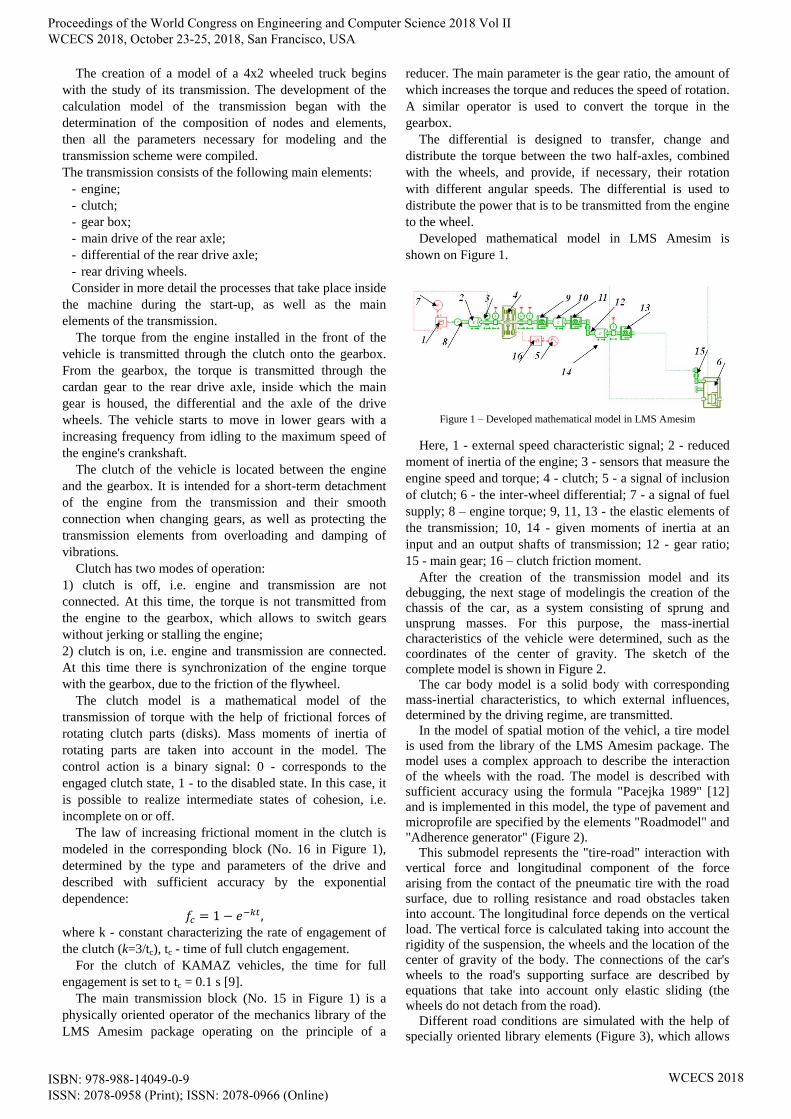
clutch disk. In general, the characteristic of the engine,
depending on the mode of operation, is a region bounded by
branches of external and regulatory characteristics (Figure
8).
Figure 8 – Static engine characteristic
The results of virtual tests confirmed the overall
performance of the model and the transmission of the
vehicle. With the gradual release of the clutch pedal, the
flywheel and the driven clutch plate are brought into
contact. The torque from the engine is transmitted to the
transmission, resulting in the rotation of the driven clutch
disc. Elements of the transmission are twisted to some angle.
When the flywheel and the clutch plate are in contact, the
engine speed drops. A further increase in the clamping force
between the flywheel and the driven clutch plate results in a
comparison of their angular velocities and the closure of the
clutch. The vehicle moves at a certain speed without
slipping.
III. CONCLUSION
Using the simulation method, the dynamics of the
vehicle's movement during starting was studied.
Experimentally proved the effectiveness of methods of
computer modeling complex dynamic processes. The result
is a developed adequate and reliable mathematical model of
a truck with a wheel formula 4x2. The developed
mathematical model of the truck allows to estimate the
general dynamics of the vehicle when starting. The model
takes into account the external dynamics of the car, the
dynamics of all major units and nodes. By simulating a
typical mode of motion, the dynamic loading of the
transmission at the moment of starting from the place is
estimated. In the course of the study, a direct calculation
was made of the maximum dynamic torque on the input
shaft of the main drive of the rear drive axle, which was
19740 Nm. Thus, the direct calculation of the dynamic
torque gives lower values than the empirical relationship. At
the same time, the moment obtained by the direct
calculation method exceeds the time limited by the coupling
properties of the road surface by 1.31 times. The obtained
calculation results allowed to estimate the values and
character of load distribution.
REFERENCES
[1] González-Cruz, C., Jáuregui-Correa, J., López-Cajún, C. et al.,
"Dynamic Behavior and Synchronization of an Automobile as a
Complex System," ASME 45837, vol.1, 2014.
[2] Annicchiaricom, C., Rinchi, M., Pellari, S. and Capitani, R., "Design
of a Semi Active Differential to Improve the Vehicle Dynamics,"
ASME 45837, vol.1, 2014. 5.
[3] Assadian, F., Hancock, M., Herold, Z., Deur, J. et al., "Modeling and
Experimental Validation of Active Limited Slip Differential Clutch
Dynamics," ASME 48784, 2008, pp. 295-304.
[4] Vantsevich, V. and Shyrokau, B., "Autonomously Operated Power-
Dividing Unit for Driveline Modeling and AWD Vehicle Dynamics
Control," ASME 43352, 2008, pp. 891-898.
[5] Federico Cheli. Integrated modeling of vehicle and driveline
dynamics / Federico Cheli, Marco Pedrinelli, Andrea Zorzutti //
ASME 8th Biennial Conference on Engineering Systems Design and
Analysis. – 2006. – Vol. 2, pp. 235-244.
[6] Keller, A., Murog, I. and Aliukov, S., "Comparative Analysis of
Methods of Power Distribution in Mechanical Transmissions and
Evaluation of their Effectiveness," SAE Technical Paper 2015-01-
1097, 2015, doi:10.4271/2015-01-1097.
[7] Dubrovskiy, A., Aliukov, S., Dubrovskiy, S., and Alyukov, A.,
"Basic Characteristics of Adaptive Suspensions of Vehicles with New
Principle of Operation," SAE Int. J. Commer. Veh. 10(1):2017,
doi:10.4271/2017-01-0404.
[8] Keller, A. and Aliukov, S., "Analysis of Possible Ways of Power
Distribution in an All-Wheel Drive Vehicle," in Lecture Notes in
Engineering and Computer Science: World Congress on Engineering
2015, pp. 1–5.
[9] Keller, A. and Aliukov, S., "Rational Criteria for Power Distribution
in All-wheel-drive Trucks," SAE Technical Paper 2015-01-2786,
2015, doi:10.4271/2015-01-2786.
[10] Keller, A., Aliukov, S., Anchukov, V. and Ushnurcev, S.,
"Investigations of Power Distribution in Transmissions of Heavy
Trucks," SAE Technical Paper 2016-01-1100, 2016,
doi:10.4271/2016-01-1100.
[11] Reza N., “Vehicle Dynamics: Theory and Application,” Spring, 2012,
455 p.
[12] PACEJKA, H. B. «The tyre as a vehicle component» / PACEJKA,
H. B. FISITA – Congress Prague – june 16–23th 1996.
[13] Murog, I., Scientific methods of improving transmission and steering
in the modernization of multi-purpose vehicles / PhD thesis/
Chelyabinsk, 2013.
Proceedings of the World Congress on Engineering and Computer Science 2018 Vol II WCECS 2018, October 23-25, 2018, San Francisco, USA
ISBN: 978-988-14049-0-9 ISSN: 2078-0958 (Print); ISSN: 2078-0966 (Online)
WCECS 2018