modeling ofpile footings and drilled shafts for seismic design
TRANSCRIPT

IIleEEf!DISCIPLINARY CENTER FOR EARTHQUAKE ENGINEERING RESEARCH
tional Center of Excellence in Advanced Technology Applications
N 1520-295X
1111111111111111111111111111111PB99-157257
Modeling of Pile Footings andDrilled Shafts for Seismic Design
by
1. PoLam, M. Kapuskar and D. ChaudhuriEarth Mechanics, Inc.
17660 Newhope Street, Suite EFountain Valley, California 92708
Technical Report MCEER-98-0018
December 21, 1998REPRODUCED BYU.S. DEPARTMENT OF COMMERCE
NATIONAL TECHNICALINFORMATION SERVICE'SPRINGFIELD, VA 22161
This research was conducted at Earth Mechanics, Inc. and was supported by theFederal Highway Administration under contract number DTFH61-92-C-00112.

NOTICE
This report was prepared by Earth Mechanics, Inc. as a result of researchsponsored by the Multidisciplinary Center for Earthquake Engineering Research (MCEER) through a contract from the Federal HighwayAdministration. Neither MCEER, associates of MCEER, its sponsors, EarthMechanics, Inc., nor any person acting on their behalf:
a. makes any warranty, express or implied, with respect to the use ofany information, apparatus, method, or process disclosed in this report or that such use may not infringe upon privately owned rights;or
b. assumes any liabilities of whatsoever kind with respect to the use of,or the damage resulting from the use of, any information, apparatus,method, or process disclosed in this report.
Any opinions, findings, and conclusions or recommendations expressedin this publication are those of the author(s) and do not necessarily reflectthe views of MCEER or the Federal Highway Administration.

50272-101REPORT DOCUMENTATION 1. Report No. 2. 3. Recipient's Accession No.
PAGE MCEER-98-0018
4. Title and Subtitle 5. Report DateModeling of Pile Footings and Drilled Shafts for Seismic Design December 21,1998
6.
7. Authors 8. Performing Organization Report No.I. PoLam, M. Kapuskar and D. Chaudhuri
10. ProjectlTask/Work Unit No.112-D-3.5 and 112-D-3.6
9.Performing Organization Name and Address 11. Contract(C lor Grant (G) No.Earth Mechanics, Inc., 17660 Newhope Street, Suite E, Fountain Valley, California 92708 (C) DTFH61-92-C-00112
(G)
12. Sponsoring Organization Name and Address 13. Type of Report &Period CoveredMultidisciplinary Center for Earthquake Engineering Research Technical reportState University of New York at BuffaloRed Jacket Quadrangle, Buffalo, NY 14261
14.
15. Supplementary NotesThis research was conducted at Earth Mechanics, Inc. and was supported by the Federal Highway Administration under contract number DTFH61-92-C-00112.
16. Abstract (limit 200 words)This report documents two studies that were conducted to review, assess, and provide recommendations regarding the seismic design of bridgefoundations. Specifically, the report addresses modeling approaches and parameters that affect the seismic design and response of pile groups anddrilled shafts. The report attempts to bridge the interface between the structural and geotechnical design process by describing a two-step design andanalysis procedure for these bridge foundation components. Recent research results on pile group effects and the design of pile foundations to resistlateral spreading of liquefiable soils are also reviewed. Recommendations are provided concerning: modifications to p-y curves to account for cyclicloading conditions, pile group effects and soil-pile interaction behavior, and development of p-y curves for the design of drilled shafts.
17. Document Analysis a. DescriptorsEarthquake engineering. Seismic design. Drilled shaft foundations. Pile group foundations. Bridges. Loading. Modeling. Stiffness. Lateral groundspreading. Seismic response. Soil-pile interaction.
b. Identifiers/Open-Ended Terms
c. COSATI Field/Group
18. Availability Statement 19. Security Class (This Report) 21. No. of PagesRelease unlimited. Unclassified 151
20. Security Class (This Page) 22. PriceUnclassified
(see ANSI_Z39.18)

.,. .....'
:.g Fj~<Ao
c.n

IlIJlTIDI!CIPUNARf lOOIR FOR EARIHQI.II.IE ENGINURlNG RElEARal
ANatiooal C""ff«fJ"'""" inAiMnt:td TtdInoIo!lY1fpIicalioos
Modeling of Pile Footings and Drilled ShaftsFor Seismic Design
by
1. PoLam1, M. Kapuskar2 and D. ChaudhurP
Publication Date: December 21, 1998Submittal Date: January 31, 1998
Technical Report MCEER-98-0018
Task Numbers 112-D-3.5 and 112-D-3.6
FHWA Contract Number DTFH61-92-C-00112
PROTECTED UNDER INTERNATIONAL COPYRIGHTALL RIGHTS RESERVED.NATIONAL TECHNICAL INFORMATION SERVICEU.S. DEPARTMENT OF COMMERCe
1 Principal, Earth Mechanics, Inc., Fountain Valley, California2 Project Engineer, Earth Mechanics, Inc., Fountain Valley, California3 Staff Engineer, Earth Mechanics, Inc., Fountain Valley, California
MULTIDISCIPLINARY CENTER FOR EARTHQUAKE ENGINEERING RESEARCHUniversity at Buffalo, State University of New YorkRed Jacket Quadrangle, Buffalo, NY 14261


Preface
The Multidisciplinary Center for Earthquake Engineering Research (MCEER) is a national center ofexcellence in advanced technology applications that is dedicated to the reduction ofearthquake lossesnationwide. Headquartered at the University at Buffalo, State University of New York, the Centerwas originally established by the National Science Foundation in 1986, as the National Center forEarthquake Engineering Research (NCEER).
Comprising a consortium of researchers from numerous disciplines and institutions throughoutthe United States, the Center's mission is to reduce earthquake losses through research and theapplication of advanced technologies that improve engineering, pre-earthquake planning andpost-earthquake recovery strategies. Toward this end, the Center coordinates a nationwideprogram of multidisciplinary team research, education and outreach activities.
MCEER's research is conducted under the sponsorship of two major federal agencies, theNational Science Foundation (NSF) and the Federal Highway Administration (FHWA), and theState of New York. Significant support is also derived from the Federal Emergency ManagementAgency (FEMA), other state governments, academic institutions, foreign governments andprivate industry.
The Center's FHWA-sponsored Highway Projectdevelops retrofit and evaluation methodologies forexisting bridges and other highway structures (including tunnels, retaining structures, slopes,culverts, and pavements), and improved seismic design criteria and procedures for bridgesand other highway structures. Specifically, tasks are being conducted to:• assess the vulnerability of highway systems, structures and components;• develop concepts for retrofitting vulnerable highway structures and components;• develop improved design and analysis methodologies for bridges, tunnels, and retaining
structures, which include consideration of soil-structure interaction mechanisms and theirinfluence on structural response;
• review and recommend improved seismic design and performance criteria for new highwaystructures.
Highway Project research focuses on two distinct areas: the development of improveddesign criteria and philosophies for new or future highway construction, and the development ofimproved analysis and retrofitting methodologies for existing highway systems and structures.The research discussed in this report is a result of work conducted under the newhighway structures project, and was performed within Task 112-D-3.5(a), "Develop Analysis andDesign Procedures for Pile Footings" and Task 112-D-3.6, "Develop Analysis and Design Procedures for Drilled Shafts" as shown in the flowchart on the following page.
The overall objective ofthese tasks was to develop seismic design proceduresfor two types oftypicalbridge foundations: pile footings and drilled shafts. This report reviews, assesses and providesrecommendations concerning design guidelines for each of these foundation types. For both typesoffoundations, a two-step process was developed and various parameters that affect predictedfoundation response are identified. The implications of the foundation modeling process in
iii

estimating structural response is described. The research examinedthe applicability ofconventionalp-y formulations in modeling soil-pile behavior, and assessed modifications to account for cyclicloading conditions, pile group effects, and soil-pile interaction behavior in liquefied soil. For bothtypes offoundations, the report attempts to integrate the structural and geotechnical engineeringpoints ofview.
iv

SEISMIC VULNERABILITY OF NEW HIGHWAY CONSTRUCTIONFHW A Contract DTFH61-92-C-00112
TASK A: PROJECT ADMINISTRATION & HIGHWAY SEISMIC RESEARCH COUNCIL "'""-
r ,. , ,Ir ,TASK B TASK 02 TASK 01 TASK 05 TASK 08
ExistingDuctility ,r- Design r--+ StructureRequire- --+ Seismic Structural
Criteria 1m portancements
Detailing AnalysisReview
• • • •TASK C TASK 06 TASK 03 TASK 04
Hazard Soils
Exposure f+- Spatial~ ~ Behavior
ReviewVariation and
Liquefaction
~Foundations
and, ,Soil-
TASK 09 Stru ctu reInteraction
NationalHazard
Exposure
~ ~ ,.
y TASK 07: STRUCTURAL RESPONSE I~
..J TASK E: IMPACT ASSESSMENT II
v


ABSTRACT
This report documents two studies that were conducted to review, assess, and providerecommendations regarding the seismic design of bridge foundations. Specifically, the reportaddresses modeling approaches and parameters that affect the seismic design and response of pilegroups and drilled shafts. The report attempts to bridge the interface between the structural andgeotechnical design process - in so doing, it describes a two-step design and analysis procedure forthese bridge foundation components. Recent research results on pile group effects and the designof pile foundations to resist lateral spreading of liquefiable soils are also reviewed.Recommendations are provided concerning: modifications to p-y curves to account for cyclicloading conditions, pile group effects and soil-pile interaction behavior, and development of p-ycurves for the design of drilled shafts.
Vll

Vlll

ACKNOWLEDGMENTS
This research was funded by the Multidisciplinary Center for Earthquake Engineering Research,Buffalo through a contract with the Federal Highway Administration. In an attempt to implementresearch findings into design practice, the authors have extracted results from research reported inthe literature, especially those funded by the FHWAlMCEER highway research programs. Thissupport gratefully acknowledged.
The authors acknowledge Dr. Hubert Law for his contributions in the production ofthis report. Dr.Ricardo Dobry of Rensselaer Polytechnic Institute and Dr. Kyle Rollins of Brigham YoungUniversity were very helpful in providing their centrifuge and full-scale pile load test data, and theirassistance is greatly acknowledged.
IX

x

SECTION TITLE
TABLE OF CONTENTS
PAGE
1 INTRODUCTION1.1 Overview 11.2 Objectives 31.3 Organization of the Report 3
2 MODELING OF PILE FOOTINGS 52.1 Introduction 52.2 Two-Step Seismic Design Process 6
2.2.1 Step 1: Determination of Seismic Demand and Foundation Stiffness 62.2.1.1 Displacement Demand 82.2.1.2 Force Demand Associated with Load Fuses 82.2.1.3. Governing Load Case for Foundation Design 102.2.1.4 Other Loading Mechanisms 102.2.1.5 Foundation Damping 10
2.2.2 Step 2: Capacity Analysis 112.2.3 Prevalent Practice for Conservatism 12
2.3 Single Pile-Head Stiffness 132.3.1 General Form 132.3.2 Appropriate Foundation Stiffness Matrix 14
2.3.2.1 Fundamental Assumptions 142.3.2.2 Stiffness Matrix from Nonlinear Analysis 16
2.3.3 Pile-Head Stiffness for Axial Load 172.3.3.1 Simplified Graphical Procedure 172.3.3.2 Stiffness for Uplift Loading 192.3.3.3 Selection of Secant Stiffness 19
2.3.4 Pile-Head Stiffness for Lateral Loading 202.3.4.1 Linear Subgrade Modulus 222.3.4.2 Embedment Effect 292.3.4.3 Relationship Between Subgrade Modulus and Soil Modulus 292.3.4.4 Presumptive Lateral Stiffness 34
2.3.5 Foundation DisplacementIRotation Criteria 352.4 Pile-Group Stiffness 35
2.4.1 Rigorous Method Using Static Equilibrium 352.4.1.1 Special Case of Plumb Pile Group 37
2.4.2 Simplified Method Using an Equivalent-Cantilever Approach 372.4.2.1 Equivalent Cantilever Model Parameter for Lateral Loading 402.4.2.2 Cantilever Model Matched to Diagonal Stiffness 402.4.2.3 Cantilever Model Matched to Translational and Cross Coupling Stiffness 412.4.2.4 Axial and Torsional Stiffness 41
Xl

TABLE OF CONTENTS - Cont'd
SECTION TITLE
2.5 Pilecap Stiffness2.5.1 Previous Research on Interaction Between Pile and Pile Cap2.5.2 Recommendation for Incorporating Pile Cap Stiffness2.5.3 Passive Earth Pressure for Sand2.5.4 Passive Earth Pressure for General c-$ Soils2.5.5 Typical Earth Pressure Coefficients for Design2.5.6 Pile Cap Displacement
2.6 Nonlinear Load-Deflection Sensitivity Study2.6.1 Background on p-y Curves2.6.2 p-y Curves versus Terzaghi's Subgrade Modulus2.6.3 Sensitivity to Various Aspects of Soil-Pile Modeling Assumptions2.6.4 Pile Group Effects for Typical Pile Footings
2.6.4.1 Group Effects from Elastic Halfspace Theory2.6.4.2 Group Effects from Experimental Studies
2.6.5 Group Effects for Extremely Large Pile Groups2.6.6 Pile Design in Liquefiable Soils
2.6.6.1 Design for Structural Loading2.6.6.2 Design Issues Related to Lateral Ground Spread
3 MODELING OF DRILLED SHAFTS3.1 Introduction3.2 Seismic Design Procedure For Drilled Shafts
3.2.1 Step 1: Modeling of Foundation Stiffness3.2.1.1 Coupled Foundation Stiffness Matrix3.2.1.2 Equivalent Cantilever Beam3.2.1.3 Uncoupled Foundation Springs3.2.1.4 Foundation Nonlinearity3.2.1.5 Foundation Geometry3.2.1.6 Boundary Conditions3.2.1.7 Other Considerations
3.2.2 Step 2: Estimating Foundation Capacity3.2.2.1 Prevalent Practice for Conservatism3.2.2.2 Formation of Plastic Hinge3.2.2.3 Shear Capacity3.2.2.4 Minimum Pile Length
3.3 p-y Model For Drilled Shafts3.3.1 Effects of Various Parameters
3.3.1.1 Soil Properties3.3 .1.2 Degradation Effect3.3.1.3 Embedment and Gapping or Scouring
xu
PAGE
424243454747475050505456575762656570
757576767779838385878989919192959698999999

TABLE OF CONTENTS - Cont'd
SECTION TITLE
3.3.2 Load Transfer Mechanism of Laterally Loaded Piles3.3.3 Installation Procedure3.3.4 Observation From Load Test Data3.3.5 Observations From Analytical Results
4 SUMMARY AND CONCLUSIONS4.1 Summary4.2 Conclusions and Recommendations
5 REFERENCES
Xlll
PAGE
103106106107
109109
113

xiv
FIGURE TITLE
LIST OF ILLUSTRATIONS
PAGE
1-1
2-12-22-32-42-52-62-72-82-92-102-112-122-132-142-152-162-172-182-192-202-212-222-232-242-252-262-272-282-292-30
3-13-23-33-43-53-63-7
Pile Foundation Configurations
Equivalent Linear Stiffness from Nonlinear ResponseTypical Locations of Plastic Hinges (after Caltrans, 1990)Coordinate System and Stiffness DirectionsAxial Load-Displacement Graphical SolutionTypical Characteristics of Friction versus End-Bearing PilesLateral Pile-Head Stiffness (Fixed-Head Condition)Rotational Pile-Head StiffnessCross-Coupling Pile-Head StiffnessLateral Pile-Head Stiffness (Free-Head Condition)Recommended CoefficientjofVariation in Subgrade Modulus with Depth for SandRecommended CoefficientjofVariation in Subgrade Modulus with Depth for ClayAdjustment Factors for Effective Stiffness for Concrete PilesLateral Embedded Pile-Head StiffnessEmbedded Pile-Head Rotational StiffnessEmbedded Pile Cross-Coupling Pile-Head StiffnessModeling Piles Using Equivalent Cantilever BeamsMethod for Passive Pressure Capacity of Pile CapCoefficients for Friction Component of Passive Pressure CapacityElastic Stiffness Based on Elastic Soil ModulusCorrelation ofp-y Curves with Terzaghi's Subgrade Stiffness for SandsCorrelation ofp-y Curves with Terzaghi's Subgrade Stiffness for ClaysSensitivity Study of Various Uncertainties in Pile Loading AnalysisResults of 4x4 Pile Group Tests in SandPile Group Effects Reflected by p-y Curve on Pile Response3-D FE Analysis using Periodic Boundary Condition for Infinite Pile GroupsResults of Group Effects at 3 Spacings for Infinite Pile GroupLoading Mechanism in Soil-Pile Interaction ProblemDegradation Coefficient ell versus Pore-Pressure Ratio from Liu and DobryTwo Generic Soil Conditions for Lateral Spread Pile Loading ProblemBending Moment from Centrifuge Lateral Spread Loading Experiment
Pile Head Stiffness RepresentationSPT Blowcount vs. Cantilever Length of Pile in Sand (After Caltrans,1990)SPT Blowcount vs. Cantilever Length of Pile in Clay (After Caltrans,1990)Pile Configuration and Load Resistance MechanismBoundary Condition and Pile ResponseModeling Soil-Pile System in Step 2 AnalysesPlastic Hinge Formation in Pile (after Priestley, 1996)
xv
2
79
15182123242526272830313233394446495153556061636467687374
78818286889093

FIGURE TITLE
LIST OF ILLUSTRATIONS - Cont'd
PAGE
3-8 Effect ofNear Ground Support 943-9 Stability Ratios of Two Piles 973-10 Effect of Soil Properties on Pile Response 1003-11 Example ofp-Multiplier on p-y Curves 1013-12 Effect ofp-Multiplier on Pile Response 1023-13 Effect of Scouring and Embedment on Pile Response 1043-14 Load Transfer Mechanisms of a Drilled Shaft (After Lam and Martin, 1986) 105
XVI

TABLES TITLE
LIST OF TABLES
PAGE
2-1 p-Multipliers (Cycle-1 Loading) from Various Experimentsat 3D Center-to-Center Spacing for 3x3 Pile Groups
XVll
57


SECTION 1INTRODUCTION
1.5 Overview
In this report, discussion is focused on the modeling and seismic design of pile group and drilledshaft foundations for bridge structures. Although the modeling approach for seismic loading issimilar for various pile types, important differences exist due to installation procedures. Theseprocedures significantly effect the appropriate input parameters as a result of i) how they areconstructed, ii) specific properties of the pile type, and iii) specific connection details at the pilehead-pile footing.
There are two general configurations where pile foundations are connected to the superstructure asshown in figure 1-1. Figure 1-1a shows an arrangement where piles are connected by a pile cap thatsupports the bridge pier or bent. This kind ofarrangement is usually adopted for conventional smalldiameter pile groups. Figure 1-1b shows an example ofa pile extension where the pile is extendedas a structural unit to support the bridge superstructure. The load supporting mechanism andresponse of these two types of foundations are different and hence the modeling approach mustaccount for these differences. In fact, the foundation types mentioned above fall into one ofthe twoconfigurations shown in figure 1-1.
The first part of this report is dedicated to pile group foundations, as they are the most commonfoundation type used in bridge structures. The treatment for this type of configuration requires anunderstanding ofpile behavior under both axial and lateral loading. Moreover, the combined effectofshear and overturning moment on pile footing behavior must be carefully addressed in modelingas well as from a seismic design standpoint. In the second part, the discussion is geared towardlateral loading on drilled shafts or pile extension type structures. In this type ofstructure, the overallas well as individual pile behavior is generally governed by the lateral loads on the bridge deckwhich in tum is reacted by the induced shear and bending moment on the drilled shafts. The bridgeresponse is relatively insensitive to axial pile response in contrast to pile footings.
In general, structural behavior under seismic loading is a function of its dynamic responsecharacteristics. Moreover, it is well known that overall structural dynamic properties are influencedby the relevant foundation properties. Therefore, for realistic evaluation ofthe structural response,it is necessary to model the force-deformation characteristics ofthe foundation and incorporate themin the analytical model of the structure.
The procedures currently used to analyze and design pile foundations under lateral and/or axial loadsare generally based on the theory of beam on elastic foundation and its nonlinear variations asembodied in p-y formulations proposed by several researchers (e.g., Hetenyi, 1946; Matlock, 1970;Reese et aI., 1974; Murchison and O'Neill, 1983; O'Neill and Gazioglu, 1984). Among the varioussources of nonlinearities within the soil-pile interaction zone are the geometric nonlinearity such asgapping, material nonlinearity in the soil behavior, etc. Since these nonlinearities would have a
1

Bridge Superstructure Bridge Superstructure
ft
I I Pile Cap
Piles/Drilled Sha
L..- L..-
(a) Pile Cap Configuration (b) Pile Extension
Figure 1-1 Pile Foundation Configurations
2

direct effect on the structural response, the most desirable way to evaluate the overall response is tointegrate the total foundation system in the analytical model of the structure. However, thisprocedure is expensive in terms of computational effort, and not suitable for routine analysis anddesign. Moreover, given the uncertainties involved in predicting the ground motion and incharacterizing the nonlinear behavior of structural and foundation elements, such a procedure maynot improve the solution. In practice, foundation stiffnesses are represented in simpler forms thatcan be readily incorporated in the structural model. Since such procedures involve somesimplifications and assumptions, the structural designer needs to be aware of the simplifyingprocedure and its implication in assessing the performance of the overall structural and foundationsystem.
1.2 Objectives
This report deals with the modeling ofpile footings and drilled shaft foundations. It is recognizedthat a technically sound bridge and supporting foundation design requires full cooperation amongstructural and foundation engineers. Therefore, this report attempts to provide an integratedviewpoint that addresses issues ofimportance to both structural and foundation engineers. In doingso, the principal objectives are to:
(l) Evaluate the effect of assumptions made in modeling the actual foundation behavior on theoverall response of the structure.
(2) Evaluate the effect of assumptions made in modeling the actual foundation behavior on theestimated displacement and force demand on the foundation as well as the overall bridgesystem.
(3) Summarize different methods used to characterize the stiffness of pile footings and drilledshaft foundations, and discuss their limitations.
(4) Provide guidelines on foundation modeling for seismic response and In subsequentfoundation capacity analysis.
(5) Provide seismic design guidelines.
1.3 Organization of the Report
This report consists of two main sections on the modeling aspects of pile footings and drilled shaftfoundations for seismic design and analysis, respectively.
Pile footings are discussed in Section 2. This section discusses the steps involved in the overalldesign process for seismic loading and reviews the role of foundation modeling in the designprocess. A general methodology to develop the stiffness matrix of individual piles is provided.Various approaches to integrate individual pile-head stiffness matrices into the pile group model arediscussed, as are the effects of soil resistance acting on the pile cap. Guidelines are given to account
3

for the additional stiffness. Finally, some nonlinear load-deflection soil-pile interaction analyses areprovided and various sensitivity issues are discussed. Background information on the widely usedp-y curve criteria with reference to the classical Terzaghi's linear subgrade theory, findings fromrecent studies on pile group effects, and issues related to design of piles in liquefiable soils arepresented.
Section 3 discusses seismic design procedures for drilled shaft foundations. Applicability ofconventional p-y models for drilled shaft foundation analysis is examined.
Section 4 contains a list of conclusions and recommendations regarding the seismic design of pilefootings and drilled shafts from a geotechnical standpoint.
4

SECTION 2MODELING OF PILE FOOTINGS
2.1 Introduction
In this section, various aspects of modeling, analysis and design of one of the most commonfoundation types, namely, pile group foundations (pile footings) are discussed. This type offoundation is typically used to support bridge superstructures. Pile foundations are used in a varietyofsubstructure configurations, such as single column, multiple column bents on common or separatepile footings, pier walls, abutment walls and very large pile groups (with several hundred piles) tosupport pier towers in major water crossings and pile extensions where individual piles are extendedabove the mudline to support the superstructure directly. Moreover, pile types used in the abovementioned foundations may vary depending on the specific site and design requirement. Among thevarious types ofpiles are driven steel pipe or HP piles, driven precast concrete piles, driven timberpiles, cast-in drilled-hole (CIDH) piles, and a variety of cast-in-place (CIP) piles.
In general, seismic design procedures involve various steps [at least] one ofwhich requires a reliablecomputational as well as analytical model ofthe structural system under consideration. Moreover,the overall structural system may be modeled and designed as uncoupled subsystems to avoidpossible difficulties that may be encountered during the design process. These subsystems can belater combined to evaluate the overall system performance. One good example ofsuch an approach,namely, substructuring approach, is usually used in modeling pile group foundations for bridges.This technique overcomes some of the difficulties (due to large number ofpiles) involved with themodeling of each pile member individually and complexities related to modeling realistic soilbehavior. In the substructuring modeling approach, the overall bridge is divided into two submodels: i) the structural model (commonly referred to as the global bridge model) which typicallyincludes the bridge deck superstructure and portion of the substructure extending down to thefoundation and ii) a foundation substructure. Typically, geotechnical engineers are responsible forfoundation modeling (or input parameters to the foundation model), whereas the structural engineersare responsible for modeling the global model. The first step in modeling the foundation would beto establish, with input from the structural engineers, the appropriate interface between the two submodels (e.g. at the base of the column, at the centroid of the pile cap, or at the base of the pile cap,etc.). The following sections discuss various aspects of the procedures used for the foundationsubstructuring approach.
Depending on the type of analysis/design procedure adopted, relevant linear, nonlinear and/orequivalent linear properties of the modeled elements should be determined. Such properties can bebest incorporated in analyses in terms of stiffness of pile elements which are determined based onspecific pile force-deformation behavior. Moreover, load transfer - load supporting mechanismsshould be identified prior to any attempt to model the structural system. As mentioned before,overall seismic response ofpile group foundations generally depend on the individual pile responseunder both axial and lateral loadings. Therefore, stiffness characteristics ofvarious components inpile group foundations are discussed in the following sections for these types of loadings.
5

It has been a common practice to used p-y curves or Terzaghi's linear subgrade modulus theory(which in effect is a form ofp-y curves) in developing stiffness properties ofpiles in the surroundingsoil. These curves (p-y) are developed empirically based on observations ofpile load tests ofmostlysmaller-diameter piles installed by impact hammer driving. Some recent studies suggest that theconventional p-y curves may need to be modified for the analysis and design of large-diameterdrilled shafts. This issue will be further discussed in Section 3.
2.2 Two-Step Seismic Design Process
It is important to recognize that most of the soil-structure interaction analyses conducted bygeotechnical engineers are usually performed to support structural engineers in the design of thestructural and foundation system. It is important for geotechnical engineers to gain some degreeofappreciation ofthe overall structural design process. In general, a seismic design process involvesa two-step process. These steps are discussed in the following subsections.
2.2.1 Step 1: Determination of Seismic Demand and Foundation Stiffness
The first step to determine the seismic demand imposed on the structural system is to determine theresponse level implied by the design earthquake. Unlike static loading, dynamic loads on a structuredepends on the overall period of the structure, which in turn depends on the foundation stiffness.Therefore, a realistic estimation of foundation stiffness and integration into the structural analysisis important because it plays an important role in the assessment of seismic demand. In general, theoverall structural system (including the foundation) responds nonlinearly to the applied load fortypical seismic load levels. However, for practical purposes, linear response analyses are the mostcommon analysis types in designing bridges in which a linear stiffness representation of thefoundation is incorporated in the analytical model. Structural designers and geotechnicalrengineersshould be aware of the modeling procedure of the foundation system and the inherent limitationsassociated with the process ofthe linearization as discussed below.
In Step 1, emphasis is placed on characterizing the proper foundation stiffness to be incorporated inthe overall global structural model such that the seismic demand from the earthquake can bedetermined. Figure 2-1 shows generic load-deflection characteristics of the foundation system.Unlike structural properties, which typically have a reasonably well-defined elastic stiffness, soilsare intrinsically nonlinear, starting from extremely small load levels. For this reason, the choice ofan equivalent-linear soil modulus would be rather complex and potentially requires an iterativeprocess such that the adopted stiffness would be compatible to the deflection level. It can beassumed that a secant stiffness at peak load/deflection would represent the lower bound stiffnessoccurring only at an infinitesimal duration in time during peak earthquake load. Such a stiffnessmight be too soft to be representative for the overall duration of the earthquake. A secant stiffnessat a smaller deflection might be a better candidate to serve as the effective foundation stiffnessrepresentative for a longer time frame over the duration of the earthquake.
In the widely used equivalent-linear site response analysis procedure, Idriss and Sun (1992) proposedto establish the equivalent secant soil modulus at an effective strain value equal to the peak strain
6

300
Overshoot
-- 2000-32 Theoretical Force........"'0 I at Peak Loadco0 I
..J I
co IL-
a.> kp (Lower Bound Stiffness at Peak Load)...co I
..J 100 I
I I
I I
I I
I I
II
1 0I
eq op I
00 1 2 3 4
Pile Head Displacement, (in)
Figure 2-1 Equivalent Linear Stiffness from Nonlinear Response
7
multiplied by a scaling factor n = (Mw -1)/1 0 where Mw is the earthquake magnitude (Momentmagnitude). The above recommendations by Idriss and Sun, or the simple establishment ofa secantfoundation stiffness at 0.5 to 0.65 of peak deflection, would provide a better basis for developingfoundation stiffness than the lower-bound stiffness at peak deflection.
2.2.1.1 Displacement Demand
Various researchers (e.g., Miranda, 1991) have concluded that solutions from linear responseanalysis generally give reasonable peak superstructure displacement solutions (referred to as theequal-displacement principle for long period systems). Therefore, it can generally be assumed thatif an appropriate equivalent-linear stiffness is chosen, the linear dynamic response analysis canpredict the peak displacement. However, as shown in figure 2-1, a secant stiffness selected at a
deflection 6eq below peak deflection 6p overestimates the load at peak deflection for a typicalnonlinear load-deflection curve. The dilemma is that a secant stiffness at below the peak load shouldbe used in order to capture the average stiffness characteristics rationally, which in turn forms thebasis to predict the proper level of peak displacement. For this reason, solutions from a lineardynamic response analysis can only provide a rational basis for the displacement demand for asystem that is designed to yield (premise of a modem seismic ductile design principle).
Since the linear response analysis generally overestimates the load demand, a pseudo-static nonlinearpushover analysis is needed in a subsequent capacity analysis to account for forces correspondingto the displacement demand predicted in Step 1. The above inherent limitations in a linear responseanalysis imply that a nonlinear dynamic response analysis would be needed to solve for both forcesand displacement simultaneously in a one-step analysis for a system that has significant inherentnonlinearities.
2.2.1.2 Force Demand Associated with Load Fuses
In modem seismic design, the ductility principle is used to design the superstructure and to size thecolumn, so that a plastic hinge can form at a predetermined location (typically at the columns) duringa seismic event to limit the load transfer to the foundation and also to provide a mechanism todissipate energy. This design strategy allows for an economical foundation system and also protectsembedded foundations which are difficult to inspect for damage. Such strategies are very sound andnecessary, not just from an economic standpoint but also because of uncertainty in our knowledgeofthe earthquake load. Therefore, it would be a good practice to control the behavior under potentialover-load conditions such that damage would be limited to preferred locations associated withductile behavior in the overall system.
Figure 2-2 was extracted from the Caltrans BDS which illustrates typical locations ofplastic hinges(load fuses) and how the corresponding lateral shear load is determined based on the plastic hingemoment for foundation design. In the overall design process, it is important to design the system sothat the limit state is governed by the plastic moment capacity rather than by the shear capacity ofthe column, to ensure an overall ductile behavior. There has been a significant number of caseswhere an overly soft characterization of a foundation stiffness has misled the designer to an
8

~-- .. CG .. eG
Assume Flares Fall 0t1Assume
Flares EHective
Wall or Barrier
Me MFV=- orV=-La LF
v= Mr+Mw
Lwor
V=Mr+MB
La
(a) Transverse
V=Mr+Mw
Lwor
. Mr +MFV =---:---'-LF
V = Mn +MwLw
or
V = MFL +MeLa
Mr Mr
I
La-8
LFMa
'"
V = Mr +MeLa
(b) Longitudinal
Figure 2-2 Typical Locations of Plastic Hinges (after Caltrans, 1990)
9

overly soft overall system behavior (e.g. overly deep plastic hinge locations for drilled shafts, orconcrete barriers placed around columns led to shorter column lengths than as designed), which inturn led to underestimating the shear demand in the column, resulting in catastrophic failure inearthquakes.
2.2.1.3 Governing Load Case for Foundation Design
Theoretically, the governing foundation load should be the lower of the two conditions: (1) forcesfrom a nonlinear pushover analysis compatible with the displacement demand from dynamicresponse analysis, or (2) forces associated with load fuses inherent in the structural system (e.g.,forces associated with the plastic hinge moment of the columns). The objective in Step 1 is toquantify the seismic demand implied by the design earthquake for the overall bridge system, whichcan then be compared with the capacity obtained from the subsequent pseudo-static pushoveranalysis (see Step 2 below) to determine the adequacy of the design.
2.2.1.4 Other Loading Mechanisms
The above design process is geared toward designing for the inertial loads on the superstructureinduced by the design earthquake. It should be recognized that there are other loading mechanismsassociated with earth pressure loading on the bridge through the foundation. However, this latterload case has not been fully developed in current design codes. At poor-soil sites, especially wherethere is a potential ground instability (lateral spread associated with liquefaction or slopedeformation), this type of loading has caused most of the historical catastrophic failure of bridges.Unfortunately, the studies that investigate various design alternatives for this load case are still ina rudimentary stage. Therefore, designers need to be cognizant ofthe potential ofthe other loadingmechanisms, especially at poor-soil sites. Design for this type of loading is rather complex andrequires a higher degree of interaction with geotechnical engineers in order to implement propermeasures into the design process. Some comments on sound engineering practice for goodengineering design for these conditions are provided in Section 2.6.6.
2.2.1.5 Foundation Damping
Theoretically, various forms of damping (radiation and material or hysteretic dampings are majorsources of foundation damping) should be accounted for in design analysis. In practice,implementation offoundation damping in design often leads to difficulties, and some default valuesare assumed. In addition, precautions must be exercised to avoid misuse ofdamping in design (i.e.resulting in an overly damped design). Some ofthe difficulties include: (1) radiation damping is ratedependent and becomes less significant especially for long-span structures which typically have longperiods (typically several seconds fundamental period), (2) damping implied from elasto-dynamicapproach is frequency dependent, which is difficult to be implemented into nonlinear time historyanalyses (the analysis approach adopted for important bridge structures), (3) elasto-dynamicapproach has been known to over-predict damping because of its inherent simplification thatfoundations are bonded to the soil mass, and (4) material damping is strain dependent andtheoretically should be related to the seismic load level. It is the authors' experience that radiation
10

damping involves more implementation difficulties, whereas, accounting for hysteretic materialdamping might be more reliable and implementable. Ultimately, one major difficulty is how toimplement foundation damping in the overall bridge model in a practical manner. Very closeinteraction between structural and geotechnical experts is required to implement foundation dampingproperly. Several highway bridge research projects provided some indication that abutment dampingmight play an important role in typical overcrossing bridge structures. From system identificationstudies using actual strong motion recordings on bridge structures, as much as 30 percent abutmentdamping has been observed for specific modes ofresponse ofthe bridge involving displacement ofthe abutments. For toll bridge projects in California, where state-of-the-art soil-structure interactionanalyses are implemented in retrofit and new design projects, about la-percent foundation damping(without the superstructure) has been sometimes adopted (based on consensus opinion), unlessspecial studies are conducted on a case by case basis. When this la-percent foundation damping isimplemented into a more massive global bridge model, a much smaller damping ratio for the overallbridge structure will result in only those specific modes involving foundation displacement. Fromthe author's experience, for long period bridges, foundation damping (especially compatible to adesign strategy to achieve essentially elastic response in the foundations) is a secondary design issue.
2.2.2 Step 2: Capacity Analysis
Because a linear response analysis usually over-predicts the load level (see previous section), anotheranalytical step is usually needed to calculate a more realistic force in the system (includingfoundation forces) ifthe seismic demand arises from a linear dynamic response analysis. In Step 2,the complete structure and foundation with the surrounding soil is usually modeled, includingstructural nonlinearity in a static (pushover) analysis of the bridge-foundation system to determinethe displacement level where structural yielding is initiated (i.e., to determine yield displacement)and how the load is distributed to various structural components at various load levels (up to thedesign earthquake load level).
On the basis of the analyses, the foundation capacity is evaluated and compared to the demanddetermined from Step 1 to determine the adequacy for structural integrity for the design earthquake.The ratio of the displacement demand versus yield displacement is the ductility demand which canbe used to evaluate whether there is adequate capacity as compared to the seismic demand associatedwith the earthquake.
It is our experience that in Step 2 capacity solution, it is more important to properly account for thestructural nonlinearity than soil nonlinearity. However, within the context of the pseudo-staticmonotonic loading condition, the currently available numerical tools can incorporate nonlinear soilbehavior rather easily and we encourage that nonlinear soil behavior (e.g., p-y curves) be includedin pushover analysis (Step 2). In many cases, a linearized representation ofsoil stiffness such as theTerzaghi's subgrade modulus approach could provide reasonable solutions for design applications.
For a laterally-loaded pile problem, usually there is ample soil capacity (ultimate passive pressurefrom soil) distributed over the entire pile length. The foundation system capacity is usuallycontrolled by the structural capacity or the tolerable displacement of the overall bridge. The
11

appropriate analysis to determine the foundation capacity for lateral earthquake load relates to theassessment of the magnitude of lateral deflection that can be tolerated by the bridge and thefoundation's ability to provide vertical support to structures within acceptable performance(settlement). For earthquake design (which usually implies extremely high loads in states with highseismicity, but at a relatively low probability ofoccurrence), the structural system is expected to bedamaged and will undergo some level of yielding. At any rate, the state-of-practice in the Step-2analysis usually involves a higher degree of sophistication in terms of system modeling (e.g.,involving some form ofnonlinearity) as compared to the Step 1 seismic demand analysis. Becausethe demand and capacity models are usually incompatible, it is important to discuss how results inthe seismic demand solutions from Step 1 are related to the capacity solutions from Step 2.
As discussed earlier, results in the Step 1 dynamic analysis are usually used to establish thedisplacement demand. In the Step 2 static pushover analysis, the first step would be to determinewhether one should conduct the analysis to the level of prescribed displacement or force. Asmentioned earlier, if the demand arises from a linear dynamic response analysis, the force leveldirectly from the solution might be too high and an alternate static pushover analysis would be morevalid to determine the load demand at the displacement amplitude determined from Step 1.Therefore, results from a linear dynamic response analysis is typically used to establish the level ofdisplacement demand. However, ifthe governing foundation load arises from forces correspondingto plastic hinge moment of the column, then it would be more valid to treat the loading conditionin this Step 2 analysis as prescribed load, even if an existing equivalent linear stiffness was used forthe foundation. The governing load on the foundation is the lower of the two cases (i.e. forces fromnonlinear pushover to the displacement demand or forces associated with plastic hinge moment).
2.2.3 Prevalent Practice for Conservatism
Because of uncertainties in soil behavior, geotechnical engineering tends to involve some inherentconservatism in traditional practice. Both geotechnical and structural engineers often assume thata softer soil stiffness and a lower soil capacity will lead to a more conservative design. Thisassumption is true only when the foundation is designed in a force-controlled analysis, such as deadload in settlement analyses or when the design force is associated with plastic hinging at the column.For that fixed-load case, a softer soil will obviously develop a greater displacement and a lowerfactor of safety. However, as discussed above, a seismic design process often involves a staticpushover analysis to a specified displacement rather than to a well defined load. In such cases, asofter soil stiffness in the analysis will often imply a lower force in the structural components andwould be unconservative.
Another example that prevalent conservatism might be counter-productive is that a softer foundationstiffness often results in a more even distribution of the structural load (e.g. column load) amongindividual columns or foundations. This is particularly true for battered pile groups where the loaddistribution to foundations are controlled by kinematic constraints rather than static equilibriumconsiderations, and a softer pile stiffness will usually result in a more even load distribution amongvarious piles.
12

For drilled shaft foundations, an overly soft soil stiffness also can mislead the designers to concludethat the plastic hinge will occur at a deeper location below grade which often leads tounderestimating the shear demand in the shaft.
From our experience, it can be counter-productive to introduce arbitrary conservatism ingeotechnical recommendations for seismic design. It is recommended that analysis and design forthe seismic load case be conducted using a best-estimated scenario. However, this statement onlyapplies to the seismic load case, especially for situations where the seismic demand is associatedwith dynamic response solutions, rather than associated with plastic hinge mechanisms (e.g. for pierwalls in the transverse loading direction). Traditional conservatism should be maintained infoundation design for other load cases, where the loads are usually better defined to allow engineersto judge the level ofconservatism. A better approach to account for uncertainty in the soil behaviorwould be to characterize a range of potential foundation and soil behavior (i.e., to provide bestestimates as well as upper and lower-bound recommendations) which imply the need to design formultiple sets of foundation conditions. However, this could result in undue complexity andconservatism in the design process resulting in costly foundations. Therefore, it is also importantto gain an appreciation where such higher level of complexity is necessary.
2.3 Single Pile-Head Stiffness
2.3.1 General Form
Characterization of the stiffness characteristics of an individual pile involves an evaluation of thepile load-displacement behavior for both axial and lateral loading conditions. The overall pile-soilstiffness can be estimated in a number of ways, and the method used should reflect the soilcharacteristics (e.g., type, strength and nonlinearity) and the structural properties of the pile (e.g.,type, axial and bending stiffnesses, diameter, length and structural constraints).
The stiffnesses of a single pile can be represented by a positive definite, symmetric matrix in thelocal coordinate system of the pile with the following coefficients:
Kx / 0 0 0 0 0
K/ 0 0 0 Kyl(}/
KZI 0 -Kz l{}y I 0Kpile = (2-1)
Kexl 0 0
(symm.) K{}yl 0
K(}/
where Kx ' is the axial stiffness,Ky ' and Kz ' are the lateral stiffnesses,Ky '(J;' and Kz 'By' are corresponding coupled stiffnesses between shear and overturning moment,
13
K Bx , is the torsional stiffness, andK(Jy' and K(}z, are the bending stiffnesses.
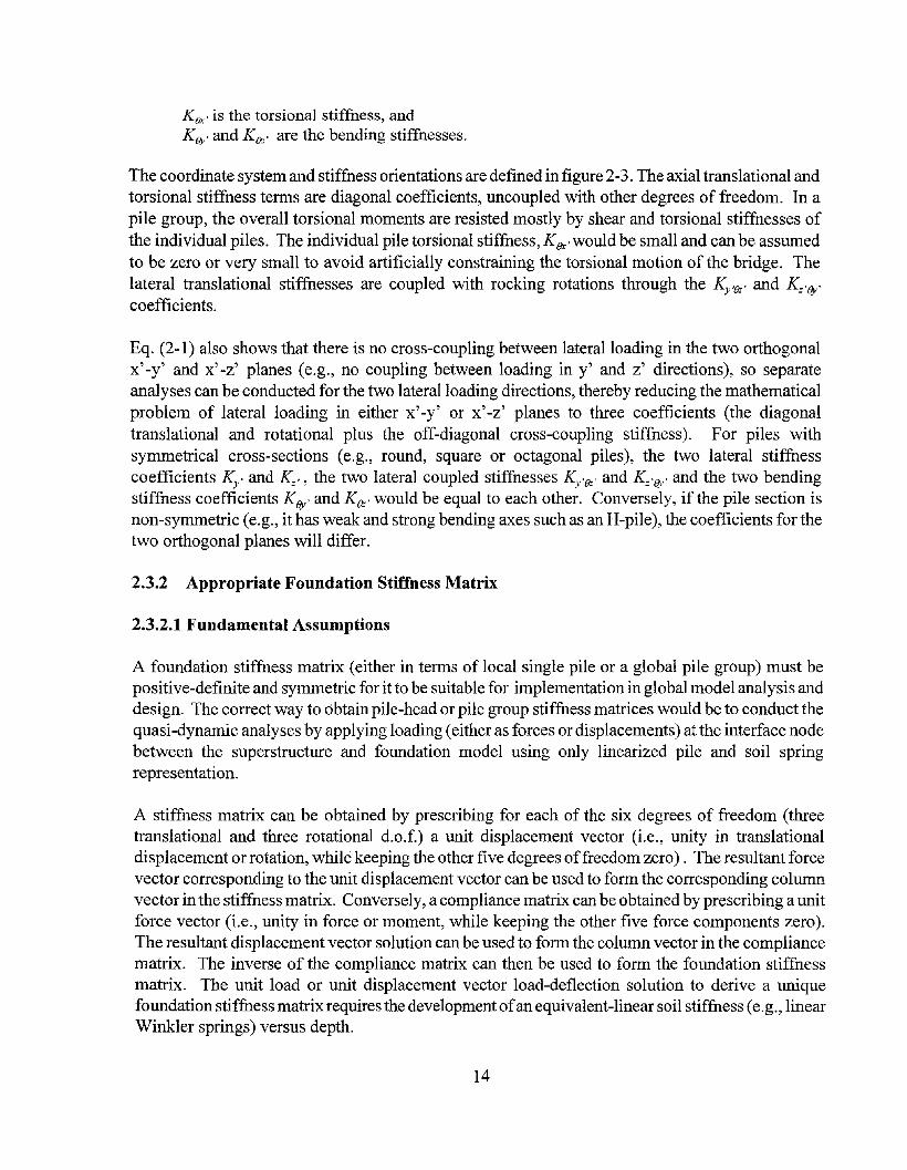
The coordinate system and stiffness orientations are defined in figure 2-3. The axial translational andtorsional stiffness terms are diagonal coefficients, uncoupled with other degrees of freedom. In apile group, the overall torsional moments are resisted mostly by shear and torsional stiffnesses ofthe individual piles. The individual pile torsional stiffness, KBx ,would be small and can be assumedto be zero or very small to avoid artificially constraining the torsional motion of the bridge. Thelateral translational stiffnesses are coupled with rocking rotations through the Ky'(}z' and K=,(Jy'coefficients.
Eq. (2-1) also shows that there is no cross-coupling between lateral loading in the two orthogonalx'-y' and x'-z' planes (e.g., no coupling between loading in y' and z' directions), so separateanalyses can be conducted for the two lateral loading directions, thereby reducing the mathematicalproblem of lateral loading in either x' -y' or x' -z' planes to three coefficients (the diagonaltranslational and rotational plus the off-diagonal cross-coupling stiffness). For piles withsymmetrical cross-sections (e.g., round, square or octagonal piles), the two lateral stiffnesscoefficients Ky' and K=" the two lateral coupled stiffnesses Ky'(}z' and K= '()y , and the two bendingstiffness coefficients K(Jy' and K(}z, would be equal to each other. Conversely, if the pile section isnon-symmetric (e.g., it has weak and strong bending axes such as an H-pile), the coefficients for thetwo orthogonal planes will differ.
2.3.2 Appropriate Foundation Stiffness Matrix
2.3.2.1 Fundamental Assumptions
A foundation stiffness matrix (either in terms of local single pile or a global pile group) must bepositive-definite and symmetric for it to be suitable for implementation in global model analysis anddesign. The correct way to obtain pile-head or pile group stiffness matrices would be to conduct thequasi-dynamic analyses by applying loading (either as forces or displacements) at the interface nodebetween the superstructure and foundation model using only linearized pile and soil springrepresentation.
A stiffness matrix can be obtained by prescribing for each of the six degrees of freedom (threetranslational and three rotational d.o.f.) a unit displacement vector (i.e., unity in translationaldisplacement or rotation, while keeping the other five degrees offreedom zero). The resultant forcevector corresponding to the unit displacement vector can be used to form the corresponding columnvector in the stiffness matrix. Conversely, a compliance matrix can be obtained by prescribing a unitforce vector (i.e., unity in force or moment, while keeping the other five force components zero).The resultant displacement vector solution can be used to form the column vector in the compliancematrix. The inverse of the compliance matrix can then be used to form the foundation stiffnessmatrix. The unit load or unit displacement vector load-deflection solution to derive a uniquefoundation stiffness matrix requires the development ofan equivalent-linear soil stiffness (e.g., linearWinkler springs) versus depth.
14

SUBSTRUCTURE
SUPERSTRUCTURE
~~ Batter angle
I,I.II,I
Ky
ebK9YIy
INDIVIDUAL PILE
FOUNDATION NODE
IN STRUCTURAL MODEL
Figure 2-3 Coordinate System and Stiffness Directions
15

2.3.2.2 Stiffness Matrix from Nonlinear Analysis
There is an abundance of computer programs commercially available today that can performnonlinear pushover analyses utilizing nonlinear p-y curves for either single piles (e.g., LPILE byENSOFT, 1997; COM624 by Reese, 1980; BMCOL76 by Matlock et. aI., 1981), or a pile group(e.g., GROUP by ENSOFT, 1997; PASS by Bryant et aI., 1977). As a result, many geotechnicalengineers derive the foundation stiffness matrix by conducting load-deflection analyses using elasticpiles embedded in soils modeled by nonlinear p-y springs for lateral soil resistance and nonlineart-z springs for axial soil resistance. Secant lateral shear and the corresponding coupled stiffnessesare then developed from the shear load vs. deflection and shear load vs. rotation curves. Similarly,secant rotational stiffnesses are developed from nonlinear moment vs. rotation curves. However,such procedures have led to ill-defined stiffness matrices (i.e., non-positive definite stiffnessfoundation matrices) in many projects and caused numerical problems when they are used in globalresponse analyses. This is because the various terms of the stiffness matrix from these nonlinearload-deflection analyses (i.e. lateral, moment and coupled stiffnesses) are associated with differentdeformed pile shapes which would imply distinctly different sets of equivalent linear soil springsfor each run. Even for a proportional loading condition, each point on the nonlinear load-deflectioncurve as shown in figure 2-1 implies its own stiffness matrix corresponding to a specific equivalentlinear soil stiffness distribution with depth. The superposition ofseparate nonlinear load-deflectionsolutions to form a stiffness matrix violates the basis for linearity and uniqueness, and couldtherefore lead to an ill-defined stiffness matrix.
To ensure a well-conditioned, unique positive-definite and symmetric stiffness matrix, irrespectiveof the loading condition used for the dynamic analysis, the pile-soil system should be linearized.This can be done by conducting the above static pushover analysis with nonlinear soil supportcurves, and extracting linear secant p-y and t-z stiffness from the p-y and t-z curves on the basis ofthe deflected pile shape. The resultant equation of motion of the pile-soil system can then bestatically condensed upward to the interface node to develop the 6x6 pile submatrix, or directlysolved to obtain the load-deflection solutions. Such operation (static condensation or direct loaddeflection solution) do not require any assumption of the form of the foundation stiffness matrix(such as that shown in eq. (2-1)). For a pile group involving irregular patterns or battered piles, theform of the foundation stiffness matrix can be rather complex and the discussed procedure shouldbe used to systematically solve for both the form and the numerical values of the stiffness matrixcoefficients.
One method to ensure that the stiffness matrix is positive-definite would be to invert the stiffnessmatrix to develop the compliance matrix and then check that the diagonal terms in the compliancematrix are all positive. Merely the fact that all diagonal terms of the stiffness matrix are positivedoes not guarantee a positive-definite stiffness matrix because ofthe cross-coupling stiffness terms.While shallow foundations can usually be represented adequately by diagonal stiffness matrices (i.e.,all off-diagonal stiffness coefficients can be assumed to be zero), deeply embedded foundationsgenerally imply a high degree ofcross-coupling between the lateral translational and the rotationalterms, and therefore the cross-coupling term must be properly taken into account in the derivationand implementation of the foundation stiffness and compliance matrices.
16

2.3.3 Pile-Head Stiffness for Axial Loading
Generally, it can be assumed that the axial pile-head stiffness in the local pile coordinate axis isuncoupled with other degrees offreedom and it is rather trivial to avoid non-physically based (nonpositive definite) stiffness matrices in the characterization ofthe axial pile stiffness term. Also, axialload-displacement characteristics can be assumed to be effectively uncoupled with the lateral loaddeflection behavior because much ofthe soil resistance associated with axial loading will come fromrelatively deep elevations and thus is relatively insensitive to the shallower soil-structure interactionzone associated with lateral loading. However, since the overall soil resistance for axial loading isderived along a significant length ofthe pile (especially at the deeper soil strata), and the pile wouldbe under a relatively large ambient dead load prior to the earthquake, a realistic consideration ofaxial pile characteristics requires the ability to account for inhomogeneous soil layering as well asplastic slippage in the upper part of the pile. Therefore, linear homogeneous analytical solutionswould have relatively minor practical applications in axial pile loading problems.
2.3.3.1 Simplified Graphical Procedure
A simple graphical procedure has been developed by Lam and Martin (1986) for developing theaxial pile stiffness coefficient (Kx )' The method inherently accounts for both soil layering andplastic soil-pile slippage interface behavior. The procedure is illustrated in figure 2-4 and consistsof the following steps:
(1) Ultimate compressive capacity. Ultimate pile capacity is developed from a site-specific pilecapacity analysis using conventional procedures for skin-friction and end-bearing capacitiesfor the different soil layers. In assigning the skin-friction and end-bearing capacities, oneshould properly account for, among others, the construction method (e.g., predrilling, drivingetc.), special conditions (e.g., consolidation due to surcharging, corrosion) and dynamic soilbehavior (e.g., cyclic strength degradation, soil liquefaction) and strain-rate effects.
(2) Rigid-pile load-displacement curve. Based on the estimated ultimate capacity, a pile loaddisplacement curve shape is developed using published skin-friction and end-bearing versuspile displacement relationships. The resulting load-displacement curve in figure 2-4 obtainedas the sum of the skin-friction and end-bearing capacities at each axial pile displacementswill result in a pile-head load-displacement relationship for a rigid pile assumption. Thiscurve constitutes a lower bound for the actual pile displacements.
(3) Flexible-pile load-displacement curve. When the pile is treated as a column without soil, themaximum additional compliance related to elastic deformation of the pile with a sectionmodulus AE, a length L for an axial load Qcan be developed as
o(Q)QL
AE
17
(2-2)

-roI:AL pILE CAPACIT"f, Q u = 278 Ie
8-r-----.,....-----.-----r-----r----,(1')
= 202 k
F = Fmax (2 ~Z/Ze - Z/Ze )
Ze= 0.2 in.
al1)(\J
TIP RESISTANCE CURVE:Q = 0 {z/z )1/3Inax e
CYCLIC LOAD (70k) zc= 0.05 D = 0.6 in.SECANT MODULUS I
a -+__=_1.;..'2r-0...;O--..,;,k.;../1.;..·n.;..,-r- + -t-__---;
,.-.,
0) a0.0
8r1 (\J
~
0 0a: l1)
D ~
--l
--la: 0- C)
X ~
a:
aLD
1.250.7S 1. 00
(i o. )0.25 O.SO
DISPLACEMENT0.00
Notes:
Load displacement curves for most soil and pile conditions willresemble rigid pile behavior at extremely small load levels, thenprogress to flexible pile behavior at higher load level (ultimatecapacity range). Our experience indicates that for most designconditions, the average stiffness from the rigid and the flexiblepile solutions will provide reasonable axial pile stiffness forearthquake design.
Figure 2-4 Axial Load-Displacement Graphical Solution
18

The flexible pile solution can then be obtained by adding the additional displacement valuesshown in eq. (2-2) to the rigid-pile load-displacement curve in figure 2-4 at different pileloads Qcorresponding to the rigid pile load-displacement curve. This curve provides anupper bound for the actual pile displacements.
(4) "Actual Anticipated" load-displacement curve. The appropriate axial load-displacementsolution will be bounded by the two (rigid and flexible load-displacement) solutions derivedin Steps 2 and 3. The actual load-displacement curve would depend on the specific pile-soilsystem. Generally, the average ofboth solutions will be a good approximation. For an endbearing pile, the appropriate curve may be closer to the flexible pile solution. In general, atsmall load levels, the upper portion of the pile is compressed first, and thus the loaddisplacement curve will be closer to the rigid-pile curve at small load. At higher loads,slippage occurs along most of the pile and the solution might migrate closer to the flexiblepile curve.
(5) Axial pile stiffness. Finally, an axial secant stiffness to be implemented into the axialstiffness coefficient in eq. (2-1) can be estimated from the anticipated load-displacementcurve compatible with the axial compression load or the considered displacement range. Fordynamic analyses, the secant stiffness would typically extend from the curve's origin to thelevel of cyclic load amplitude. For regular highway bridge foundation piles, typical levelsof cyclic compression loading would be in the range from 50 to 70% of the ultimate pilecapacity.
2.3.3.2 Stiffness for Uplift Loading
If the axial stiffness is to be used for uplift loading only, the above procedure can be used to obtainthe corresponding uplift load-displacement backbone curve by use ofskin-friction capacity for upliftloading, ignoring the end-bearing capacity.
2.3.3.3 Selection of Secant Stiffness
The load-displacement curve (either the compression or the tension loading curves) represents theexpected initial load-displacement (referred as the backbone curve) at the pile head. For axialloading, prior to the earthquake, the pile would be subjected to a large ambient static dead load andthe appropriate secant stiffness for earthquake response should reflect the hysteretic loading,unloading and reloading behavior which can be approximated by the secant stiffness extending fromthe origin to the cyclic load amplitude in compression. A secant stiffness from the zero origin to thepeak earthquake load (i.e., the sum ofambient static plus cyclic load) tends to be too soft to representthe stiffer unloading reloading stiffness.
More refined nonlinear solutions can be derived from computer analyses (e.g. Lam and Law, 1994)with distributed t-z curves to model the skin frictional behavior along the pile along with a Q-u curveto represent the end-bearing behavior. The actual axial loading behavior expected for earthquakecondition can be rather complex. Other than the pile and soil condition, complexity for
19
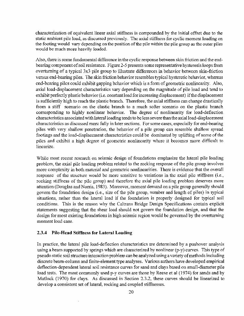
characterization of equivalent linear axial stiffness is compounded by the initial offset due to thestatic ambient pile load, as discussed previously. The axial stiffness for cyclic moment loading onthe footing would vary depending on the position ofthe pile within the pile group as the outer pileswould be much more heavily loaded.
Also, there is some fundamental difference in the cyclic response between skin friction and the endbearing component ofsoil resistance. Figure 2-5 presents some representative hysteresis loops fromoverturning of a typical 3x3 pile group to illustrate differences in behavior between skin-frictionversus end-bearing piles. The skin friction behavior resembles typical hysteretic behavior, whereasend-bearing piles could exhibit gapping behavior which is a form ofgeometric nonlinearity. Also,axial load-displacement characteristics vary depending on the magnitude of pile load and tend toexhibit perfectly plastic behavior (i.e. constant load for increasing displacement) ifthe displacementis sufficiently high to reach the plastic branch. Therefore, the axial stiffness can change drasticallyfrom a stiff scenario on the elastic branch to a much softer scenario on the plastic branchcorresponding to highly nonlinear behavior. The degree of nonlinearity for load-deflectioncharacteristics associated with lateral loading tends to be less severe than the axial load-displacementcharacteristics as discussed more fully in later sections. For some cases, especially for end-bearingpiles with very shallow penetration, the behavior of a pile group can resemble shallow spreadfootings and the load-displacement characteristics could be dominated by uplifting of some of thepiles and exhibit a high degree of geometric nonlinearity where it becomes more difficult tolinearize.
While most recent research on seismic design of foundations emphasize the lateral pile loadingproblem, the axial pile loading problem related to the rocking response of the pile group involvesmore complexity in both material and geometric nonlinearities. There is evidence that the overallresponse of the structure would be more sensitive to variations in the axial pile stiffness (i.e.,rocking stiffness of the pile group) and therefore the axial pile loading problem deserves moreattention (Douglas and Norris, 1983). Moreover, moment demand on a pile group generally shouldgovern the foundation design (i.e., size of the pile group, number and length of piles) in typicalsituations, rather than the lateral load if the foundation is properly designed for typical soilconditions. This is the reason why the Caltrans Bridge Design Specifications contain explicitstatements suggesting that the shear load should not govern the foundation design, and that thedesign for most existing foundations in high seismic region would be governed by the overturningmoment load case.
2.3.4 Pile-Head Stiffness for Lateral Loading
In practice, the lateral pile load-deflection characteristics are determined by a pushover analysisusing a beam supported by springs which are characterized by nonlinear (p-y) curves. This type ofpseudo static soil structure interaction problem can be analyzed using a variety ofmethods includingdiscrete beam-column and finite-element type analyses. Various authors have developed empiricaldeflection-dependent lateral soil resistance curves for sand and clays based on small-diameter pileload tests. The most commonly used p-y curves are those by Reese et al (1974) for sands and byMatlock (1970) for clays. As discussed in Section 2.3.2, these curves should be linearized todevelop a consistent set of lateral, rocking and coupled stiffnesses.
20

8.00
})Pil~7iii
-4.00 0.00 4.00Deformation (in.)
I
1- .: , ,.•: .
150 1-.
-50
200
-100-8.00
Pile:l ,.--.,,::::::S=F'=~
......100 t.....:..... "i/'" ..0. ."
g 50 .... ~....... + ....
Q)
~tf 0 1- .....> .......
... ,' : : : .
. . . .·········;···········s·:·····;·····:·····;··········.. . . . .
· .......................................................· .
· ...• f•.•.• .:\..... ..•.. r .. • •• • ~ ••••• ~ .
...................................................... .
.............................. ·····r····· ·... 01 •••••
2
~ 0
-12 I I I I I I I I ! , I
-0.04 -0.02 0.00 0.02 0.04 0.06Rotation (rad)
g -2E~ -4~a..~ -6o~ -8tQl> -10
··i··· .. :··· .. J· .. ·, .. ·..
. ,.J'..·....·( ..y ..i· ....'..·..
.....; ..... ~ .. , .. ;.....,. " .. :... "
.. ; ; : /.; : ..
...... ) } : ··k ..· ·
-40
-0.04 -0.02 0.00 0.02 0.04' 0.06Rotation (rad)
40
30
:2 200.
:52 10oo~ 0.......-~ -10E~ -20
-30
(a) BEhavior of Friction Pi 1 e
. .. . j 100
:.·.L.:r:;S!Z·.·..L::::::.·· ~ 50
200
2.00
Pile 7
Pile 1 :
-2.00 0.00Deformation (in.)
o
-50
150
-100-4.00
Ql~olL
0.04
~.~:~..~:~.~.~..j~.: ..~....~..~:~~..~.~..~.::.: ..~..~..~.~.J....:~....~.~~.:~.:~.....
I--....~.__._...:-... -. -;.. ... _. -. ........._....- -. -: _. -... -'.-' _.__.
2 I i
-2 I I iii I i I I
-0.04 -0.02 0.00 0.02Rotation (rad)
-c.......EQlEQl(,)
~ 00.(/)
isIii.~ -1tQl
>
.; ..... ·········l······~·······
T·.j.. . ,,; j .. .
... . . . ... . ~ ' "
. .•••• j ..••••••••••• ; •••••••••••••••. .
-0.02 0.00 0.02 0.04Rotation (rad)
40N
30.......
~ 200.
:.2 10000 0:sE -10Ql
Eo -20:2
-30
-40-0.04
(b) Bffiavior of End-Bearing Pile
Note: Results shown are from overturning of a typical 3x3 pile group.
Figure 2-5 Typical Characteristics of Friction versus End-Bearing Piles

2.3.4.1 Linear Subgrade Modulus
Lam and Martin (1986) found that lateral load-deflection characteristics representing the overallstiffness of the pile-soil system would only be mildly nonlinear because the elastic pile usuallydominates the nonlinear soil stiffness. Furthermore, the significant soil-pile interaction zone isusually confined to a depth at the upper 5 to 10 pile diameters. Therefore, simplified single-layerpile-head stiffness design charts are appropriate for lateral loading. Some ofsuch single-layer lineardesign charts are presented in figures 2-6 to 2-9 that make use of a discrete Winkler spring soilmodel in which stiffness increases linearly with depth from zero at grade level where the locationofthe pile-head is assumed. The representation ofa subgrade stiffness increasing linearly with depthhas been found to reasonably fit pile load test data for both sand and clay soil conditions. For thissoil-pile representation, the system is reduced to two parameters: (1) the pile bending stiffness E1and (2) a coefficient of variation in elastic subgrade modulus with depth,! The coefficient! hasthe unit of ForceNolume (FL-3
) and is used to define the subgrade modulus E., at depth z,representing the soil stiffness per unit pile length (see figures 2-6 to 2-9):
(2-3)
Values of ! for normal design working loads have been published by Terzaghi (1955) andMurchison and O'Neill (1983) for piles embedded in sand as a function of corrected StandardPenetration Test (SPT) blowcount or density (see figure 2-10). Figure 2-11 shows a correlation of! values with cohesion of clay soils (Lam et aI., 1991). For the purpose ofselecting an appropriate! value, the soil condition at the upper 5 pile diameters should be used. The two charts presented infigures 2-10 and 2-11 were based on data for smaller-diameter (12-inch) piles, but can be used forpiles up to about 24 inches in diameter.
Given a selected/value and the bending stiffness of the pile E1, lateral and rocking stiffnesses canbe directly read-off the charts shown in figures 2-6 to 2-9 (Lam et aI, 1991). The charts assume nopile top embedment, but also yield reasonable stiffnesses for shallow embedments not exceedingabout 5 feet, in which case the soil above the pile top would be neglected. An additional set ofdesign charts for lateral stiffness ofa pinned -head (i.e. zero bending moment) condition are includedin figure 2-9. If the ratio of variation in subgrade modulus as shown in figures 2-10 and 2-11 areused to derive the pile-head stiffness matrix from figures 2-6 to 2-9, the resultant pile-head stiffnessmatrix corresponds to the stiffness between about 0.25 and 2-inch pile-head deflection.
These stiffness charts are appropriate for embedded piles that are sufficiently long to approach thesolution of an infinitely long ("flexible") pile condition (this is valid for most conditions). There isa theoretical characteristic length ofthe pile-soil system that depends on both the bending stiffnessof the pile as well as the stiffness of the soil. When the ratio of the embedded pile length to thischaracteristic length exceeds a value of about 3, the pile can be regarded as an infinitely long pilefor pile-head stiffness characterization. The following equation can be used to obtain thecharacteristic length of the pile soil system:
22

r--..
---. a:z ..-4
---.....-...OJ-l
------...0~
c.D----. a0 ..-4<t:L..J:::I:
0L..JXw------- V}
(/) a(/) ...-(
L..J:z:w-w-f-(/)
'"<l'"---l<t a:z: ..--(
0f-<t---l(/)
:z:<t: r-"')0::::f- a
..--(
-
I v ~ .-- L.--
~b:::: c::::: .-f--f-'......f
~m~.- ~ ..-- f--'"
/" V I-
-=ff
,- ./' .-
f = 80 ~./'
- f = 60 "-"'- /" ........-./"': c/'"' ,.-- c/'"' ..--"'->v::-I---' ~ c/'"' ....---- L.-f--
«:~~ :::::---f-' v I---' VV------
::::::::vv~
v v ,.--
~ :...--I---'I---'f--' VL...---::::: vt::: / ,.--f-- ""'- I---'
,.-- ..--I-f--
./' ./' .- "- "-........- /" ./' , /"
~ ,.-- ....---- v '" Do< ....../"
....----~ ....----~ r'-... ).f--K f--
V.-c/'"'
v- --<.i'--"r.-" "",,-V........
........-v c/'"'
v- I---' v I'" "i' ~f - 40
~ /v
f 20v ....- v ......1' =f = 10
" " f = 5/" " f = 1v I-"'" ./' '"~
_____ v
"- f = 0.5f = 0.1
c/'"'.......
Coeff. of Variation of Soil R~etion
..............- Modulus with Depth, f (LB/IN )I I I I I I I IIIII I , I I I I II
10 10 lOll
BENDING STIFFNESS,M.e
,.-....-PI.S
,,,
10 12
EI (LB-IN 2)
P, = K£" S + K£s-e
~ = K£Q" 8 + Ks -e
K£ = 1.0765 "E. ITJ
T =(-y-) 1/5
Figure 2-6 Lateral Pile-Head Stiffness (Fixed-Head Condition)
23

-.-<
..".
0~
....--...z<{
a 0<{
....-(
a::::'-... 0m ~
--lI
Z...........
<Xl
~
-V) (J)V) 0l.L.JZ ......-i
LL..LL..
l-V)
--l« co:z:
0aI-
...-i
«I-aa::::
l'-a...-i
.... - - ~ .. "'--"-' .. - --..- - -"... . .- _ .. " _ ...- ... . ...
vv-!hv
..~ "i" ~v
~~~
vk;;; vV'
r77
./ 7./V./ ./
7X< ./ t/
~r«~v:/
V
~RD<i'.~~~ r--....i'. t'......~
f 200//./ "/ r-... ...... ........ f - tOO
"'i"/ V/ "'./ "'" -....... i'. "'- r--f = 60.// ./t/" ~ r-.... ........... ""'" r--f = to
l/.~~ ~/-?' V r--. "'--..........r--f = 5
~~v ~
~./
~r--f = 1
~~ r--f = 0.5f = 0.1
./ "/// //vh ./
V"'/V Coeff. of Variation of Soil Reaction
Modulus wilh Oeplh. f (L8/IN 3 )I I I I I I II I I I I I III
10 9 10 10 10 11
BENDING STIFFNESS, EI~.e
r--PI.S
I\
,I,I
I
I
IIII
PI = K,' & + K,s' 8
Mt = K6S ' & + Ks ·8
Ks = 1.499 ·E·I
T
T =(-y-) 1/5
Figure 2-7 Rotational Pile-Head Stiffness
24

Kte= 0.999 ·E·I
T2
T =(-y-)l/S
PI = K& . 8 + Kte ·8
~ = Kte · 8 + Ke ·8
10 10 1011
BENDING STIFFNESS, EI",.e
r'-p,.o
..
vI-'::
~~::::::~
~~~ v~:.:-v v
1"I/': ~ -" /
~ '"Y.: /'
~# rx-:::~ v V -" v
~ l><» /'v:-V
~;.--
~lXl>v
K ~..Y
~~~ t"- V
~ ~~v l.X " ./l"-
f 200'l"/ " l/'\. / ..... f 150v/ 1/ / V f'.../ '" " =
/' /' I./'-.. r-... " f = 100~C/.:!/vt-- V./ /' A" '" l/ ""- f = 80
~~~V v v/ /v "~ i"" ,,"'"" f = 60./ '"
~V V v V V V ~ l"- i"
~f'f = 40
~V vvt-- 1/V r"-i"f' r--f = 20v v f'
f = 10/ " " f = 5
-" / / " f = 1;;- i/' ",,,f = 0.5
./ -/' '"~ v~ I' f = 0.1/
/V Coef f. of Variation of Soil Reaclion
Modulus with Depth, f (LB/IH 3 )I I I I 1 I II "l I I I I I I j t
,.,.-.....CD OJ.-J
0----- ~
<D
...0:::.::::
-(/)(/)LU:z: {'-L....l...L-. 0I- ......-l(/)
<..?:z:--l0-:=> CO0 0U
I ......-l
(/)(/)
00::U
\{)
0......-l
Figure 2-8 Cross-Coupling Pile-Head Stiffness
25

r--
0..---.... ..-<:z-'--..CD-J-.....-
.0 <.0:z 00u .-;
0<l::L..J:r:
IL..Jl..LJ VJ0::::
0L.....-;
0::::0L....
(/)(/)
l..LJ:z '<:T
L.... 0L.... ...-lI--(/)
--l<I:0::::l..LJI-- l"'")
<l:: 0--l...-l
i..-'V ~
V v./ VI--' ~/ ./" L.-
V !.---' ~ V l--
!::/Sk I::::t: v v V
!.---'v
~~vI--' V V V
..............- t::::!.---'L.-(\1--' ~ ./t..-.
I........V
-.;?
l---'" V ~ -:::;::;' \. ".,
----v
--- ~ v ~, \ (...)0; f\1\
V ......... '::::/~V L.-- ../[\ .\1\ ./V .\
~~.-- v \ l'\ L\[\\ ./ V
./. I....... / I
~ ././ [::7
v'"V
~D1'\\ & iV
~ ~[).),;k
............... ./ L.-./
f 200./
f 150........ 'I'V I............ V ..... \\\ I'f = 100........- ~V 1\\\ f = 80
Vv v l\\\ f 60=
~ v !.---' ......
~f = 40V V
~
------f = 20f = 10f = 5f = 1
L.---"" \f 0.5=f = 0.1
Coeff. of Variafion of Soil Regction\'{odulus with Depth, f (La/IN ) :
I I I liltl I I t·.· . t.H0 0
10 10 10 11 10 12
BENDING STIFFNESS, EI (LB-IN2)
-PI.S
/FREE HEAD PILE STIFFNESS
2- K _ K lie
Ii K9
- 0 41 E01° IT
T =(-¥ )'/5
Figure 2-9 Lateral Pile-Head Stiffness (Free-Head Condition)
26

FRICTION ANGLE.4l'
28· 29'", __--r JrO" -:38:.::--" .-:..:-1"__-=-.5'VERY LOOSE MEDIUM VERY8-_.rL_O_O_S_E--l- -L.. -r---L__D_E_NS_E..--..L....:O:..:E:.:..N=.:S:.E-J
Recommended by Terzaghi, 1955(After O'Neill and Murchison, 1983)
55-;------J..-----I.-----+-----~.....-------J
<DU(ij
H 0-t-~---+------+--_.,.t:.::...--b1) (\J , 1""------+------1rD~
C/)
0-r-----t----t-----+----+----~
o 20 1.10 60 80
Relative Density, Dr (Percent)
JOO
Figure 2-10 Recommended CoefficientjofVariation in Subgrade Modulus with Depth forSand
27

a 2 4OLOWCOUNT (BLOWS/FT)
15 JO
oo
.........
zo-E---<~
-<>-e.t..
0ON
tJ:..tJ:..WoU o
a
\ MED. STIff\
\~SOfT
VERY SOFT
VERY STIFF
2 3COHESION (ksf)
4
H Af-~ [)
5
Figure 2-11 Recommended CoefficientjofVariation in Subgrade Modulus with Depth forClay
28

for subgrade stiffness increasing linearly with depth
for subgrade stiffness Es constant with depth
(2-4)
(2-5)
The discussed procedures are appropriate for calculating pile-head stiffnesses for typical smallerdiameter piles. For larger-diameter piles (i.e., drilled shafts) drilled and grouted in place (similar tolarge-diameter drilled shafts), there are some evidence that the above recommended coefficient!ofvariation in subgrade modulus would be too soft. Some recommendations to adjust the soil stiffnessparameters are recommended later in this report along with a mechanistic explanation for theapparent higher subgrade stiffness for large-diameter drilled shafts and other relevant topics (e.g.,effective versus gross sectional properties). For concrete piles, it has been found that the choice ofthe pile bending stiffness (reflecting cracked sectional properties) is very important. Figure 2-12 hasbeen taken from the structural design literature (Priestley et aI., 1996) to provide adjustment factorsfor the effective (e.g., cracked) bending stiffness for concrete piles.
2.3.4.2 Embedment Effect
As a result of additional overburden, soil resistance on the pile increases and the stiffnesscoefficients increase with the depth ofembedment. Figures 2-13 to 2-15 present pile-head stiffnesscoefficients for pile embedment depths of5 and 10ft based on a subgrade modulus which increaseslinearly with depth. It can be seen from these figures that the embedment effect on the stiffnessesis larger for slender piles and tends to diminish for stiffer piles, and that the lateral stiffness isaffected the most. For example, for a pile cap embedded in slightly compact sand (f-=10 pci), figure2-13 shows an increase in embedment depth from 0 to 5 ft can increase the lateral pile-head stiffnessby a factor of2.3 (slender pile) to 1.3 (rigid pile). For a depth increase from 0 to 10 ft, the stiffnessincreases from 3.5 (slender pile) to 1.5 (rigid pile) times.
These figures also illustrate that the significance of the embedment depth effect is greater in densesands. For example, for a 12-inch square concrete pile (El=6.22x10⁹ lb-in2
) embedded 5 ft, thelateral stiffness increases by a factor of 1.6 in slightly compact sand (f-=10 pci) and 2.6 in dense sand(f-=100 pci).
2.3.4.3 Relationship Between Subgrade Modulus and Soil Modulus
Vesic (1961) compared the solution for an infinitely-long beam resting on an elastic halfspace andarrived at the following relationship between the Winkler spring subgrade modulus Es and theYoung's modulus of the elastic halfspace EsDil :
29

Ast/Ag = .03
~----------A:s-.t/Ag = .02
Ast/Ag = .01
longitudinalreinforcement
ratio
0.15 0.20 0.25 0.30 0.35
AXIAL LOAD RATIO P/f~Ag
a) Circular Sections
.!f 0.60........
CD...0.70
a...Eo-<< 0.80~
rnrn~ 0.50Zr:.r:.... 0040Eo-<rn(,)... 0.30Eo-<rnj~ 0.20
0.00
0.10 0.15 0.20 0.25 0.30 0.35
AXIAL LOAD RATIO P/fcAg
b) Rectangular Sections
longitudinalreinforcement
ratio
A:iAg =.(l4
_-----------~At::s:t/Ag=.03
~t/Ag =Jl2----Ast/Ag =.01
~ 0.60..........
CD...0.70
a...Eo-<-< 0.60~
rnrn~ 0.50 ------Zr:.r:....
0.40Eo-<rn(,)... 0.30Eo-<rnj~
Ag = gross section areaAst = steel section areaIg = gross moment of inertiaIe = effective moment of inertia of crakced sectionr c = compressive strength ofunconfmed concreteP = applied axial compressive load
Figure 2-12 Adjustment Factors for Effective Stiffness for Concrete Piles (Priestley et aI,1996)
30

r---
az --<
~ro-'-----<J:>
~
\D...--.. a0 --<<t~
:I:
0~
XL..."'--' If)
V) aV) .....~
ZL...u...l-V)
-'~
<t az .....aI-«-'V)
z« ,....,~I- a
~
EMBEDMENT -0' --
- - - - 5' ---- la' L--- ~I~
....~ -- v~r = 100 1-- I~ /-
"- -"\. -- 1./ .~ l..-
---~ -~ ~
-I- "- V 1-- ....1~
v -........~~~V :::.".'" ~ I; ...... ".
~
- V ...... )<
,/ '" -......... V .....1; '" ~; y
v :- 1--- vI.--~ ~.....
V :::V I; ...........~f = 10
I f = 1v Go '\.
-- "- f 0.1V =.~
I;- v I Coe(f. of Voriation of Soil ReactionV V
I.lodulus with Depth, { (LB!IH 3 ), Ij
10 10 1011 10 12
BENDING STIFFNESS, EI (LB-INZ)
PI = KI ,8 + Klf,e
I.lt = Kif' 8 + Kf ,e
IJ" e
C- F"c
Figure 2-13 Lateral Embedded Pile-Head Stiffness
31

0
Z40 04a::::........... 0en-'I
Z
----<D
:::.::
Vl OlVl 0t....JZ -<L....L....
I--Vl
-'<t: COZ 00I--
-<
<t:I--0a::::
l'-0......
EMBEDMENTO' -5' #/ -
--- la' J} L)"J
~ /'-;;
'" -
./ /
././/~ ~ I';/7 ....~~
'/f ~~~~
1 - 100'./ ....... ......../.// l-6 r-........ 1 = 10Vd ~~ ....
'"I~ / [/ ...............1 = 1
"'" l% ::;..f = 0.1 ~
r7 ./j// h7;}.j/ Coefl. of Variation 01 Soil Refclion
Modulus with Depth, f (lB/IH ), 'I
10 10 1011 10 12
BENDING STIFFNESS. EI (LB-IN2)
PI =KI • 0 + Klo·8
Me =Klo ' & + Ko ·8
)))1\
IIe,a 1\~OCT ,r-- 1 (LS/IN 1)t- _P•. ' ~
Figure 2-14 Embedded Pile-Head Rotational Stiffness
32

0>o
---CD CO-l
0---Q>
""~t/)t/)I...JZ 1................. 0l-t/)
<:)
Z-l0-::::::> to0 0UI -U1
U100:::U
1O
0-
, ,
EMBEDMENT --O' -
---- 5'--- 10' --: /!
~/'"
z
-// ./ "./ ...~ ",t:::"
...... ~ I....v ~//
~V 1"'- ;:::;-- H-'I, :
-
~..... .......... r-,~./ :/
/''/ "'--/ , v ..... ./ ~ 1 = 100
./ / V./ "' '"~....-V ...... V .--: '....V ~P'"
~../ /V ~
/'" ~~
~/ :--...f = 10 -
f = I// ....- "./ "'-
./ "" f 0.1--:~........ =
~V Coeff. of Variation of Soil Refclion
Modulus with Deplh, I (LB/IN )• 'i
, " ,10 10 1011 10 12
BENDING STIFFNESS, EI (LB-IN2)
PI = K, . 0 + K,,·8
I.lc =K,,' 8 + K, ·8
Figure 2-15 Embedded Pile Cross-Coupling Pile-Head Stiffness
33

(2-6)
for a Poisson's ratio, v of 0.5, Es :::: Esoil , or the subgrade modulus can be approximated by theYoung's modulus of the soil.
2.3.4.4 Presumptive Lateral Stiffnesses
In addition to the above theoretical pile stiffness values, some presumptive stiffness valuescommonly adopted in practice by structural designers are provided for cross comparison. Section4.3.4.8 of the Caltrans BDS (1993) gives the following lateral stiffnesses (termed Ky ' and Kz' ineq. (1) ) based on pile load tests:
Pile type16" CIDH15" driven concrete pile12" driven concrete pile12" or 10" steel flange pile8" steel flange piletimber
Lateral pile-head stiffness (kips/in)525220201620
These stiffnesses were recommended for piles in normal soil conditions with SPT blowcounts of10 blows per foot and higher, and can be used for service load design (1/4-inch displacementcriteria).
Pile load tests at the Cypress Viaduct interpreted by Yashinksy and Zelinski (1993) led to thefollowing guidelines used for San Francisco double-deck viaduct retrofit:
Pile typeSteelConcreteRaymond step-tapered
Lateral pile-head stiffness (kips/in)Soft soil Stiff soil20 to 30 3520 4040 max. 40
It should be noted that the above stiffnesses include contribution from the passive soil stiffnessacting at the face of typical pile caps (see Section 2.4). The above presumptive stiffnesses inCaltrans BDS were originally recommended for service load design and to limit the foundation toan acceptable value ofstructural displacement due to the lateral force demands for service load cases.
34

The above Caltrans BDS recommended lateral stiffnesses were originally developed for service loaddesign. However, the above tabulated stiffnesses values could also serve as a rule-of-thumb and asa crude check on more refined site-specific solutions or for the earthquake load case.
2.3.5 Foundation Displacement/Rotation Criteria
Allowable foundation displacement (rotation) is a very important subject. However, more researchis needed to develop rational guidelines. The most comprehensive study on tolerable foundationdisplacement to-date is that conducted by Moulton et al. (1985) which suggests tolerable lateraldeflections up to 2 inches, and differential settlements arising from rotations of 0.004 rad forcontinuous structures and 0.005 rad for simply supported structures based on observation ofperformance ofexisting bridges under normal service conditions. Moulton's study suggests that theconventional 0.25-inch service load criteria might be over conservative, especially for poor soilconditions or for cantilevered pile caps such as many water crossings.
To date, there are a few guidelines on what might be regarded as tolerable foundation movement forearthquake loading. Probably the only rational approach to determine tolerable movements forearthquake loading would be on the basis ofthe level of stress or strain on structural components andcomputed displacements at expansion joints. Nevertheless, the level of tolerable foundationdisplacement observed by Moulton for service load can be regarded as a conservative criterion forthe more severe and relatively rare earthquake loading condition. A recent NCHRP project (1991)re-examined the data compiled by Moulton et al. and recommended an upper-bound limit ofangulardistortion of 0.004 rad for continuous bridges, but up to 0.008 rad for simple-span bridges. Thatreport led to Commentary C4.5.1 ofthe ATC-32 (1996) suggesting presumptive tolerable foundationrotations of0.008 rad and lateral deflections ofup to 2-inch as presumptive and conservative seismicdesign criteria. It is recommended that the designers base their decisions on specific case by caseexaminations of the level of stress and strain and displacements on specific structures whereverpossible for earthquake loading. Current design procedure is also too crude in many respect toaccurately predict relative displacements (e.g., the current procedure cannot account for spatialvariations in ground motion). Therefore, other traditional rules (e.g., minimum seat width) must stillbe observed in design practice.
2.4 Pile-Group Stiffness
2.4.1 Rigorous Method Using Static Equilibrium
A simplified, rigorous procedure to develop a linear 6x6 pile group stiffness matrix has beendescribed in Lam and Martin (1986) and incorporated into a computer program by Lam et al (1986).The procedure can be applied to any number of piles and geometric pile group configurations andassumes that the pile cap is infinitely rigid. The stiffness of a pile group is found by staticcondensation ofall pile-head stiffnesses into a single foundation node using basic matrix operations.The individual steps of this procedure are as follows (refer to figure 2-3):
35

(l) Select one of the 6 degrees of freedom (three translational and three rotational) of thefoundation node and apply a unit displacement or rotation to this degree offreedom. For thefirst degree of freedom, the pile group displacement vector would be as follows:
b x 1
by 0
5z 0D= (2-7)
Bx 0
By 0
Bz 0
(2) Perform the following Steps (a) to (e) for each pile in the group:
(a) Calculate the pile-head displacement and rotation that result from the applied pilegroup displacement vector D, taking into account the pile group geometry (e.g., pilehead offsets L~.x, flY and flZ from the pile group node). This can be achieved usinga geometric pile group-to-pile displacement transformation matrix A:
d pi1e =AD (2-8)
(b) The local pile coordinate system usually differs from the pile group coordinatesystem. The induced pile-head displacements and rotations Dpile can be transformedinto the pile coordinate system using a pile group-to-pile coordinate transformationmatrix T:
(2-9)
(c) Obtain the pile-head forces and moments resulting from the pile-head movementsdpi1eby multiplying the movements by the pile-head stiffnesses K pi1e from Section 2.3:
(2-10)
(d) Transform the pile-head forces and moments back to the pile group coordinatesystem using the inverse ofthe coordinate transformation matrix T:
(2-11)
(e) Calculate the pile group force and moment contributions resulting from the pile usingthe inverse of the geometric transformation matrix A:
F =A-I Fpi1e
36
(2-12)

(3) At the pile group node, superimpose the force and moment contributions from all piles:
F~roup =IFpiles
(2-13)
(4) The total pile group reactions F~roup are due to a unit displacement D applied in Step (1) tothe ith degree of freedom at the pile group node, and therefore represent the ith row (andcolumn) in the pile group stiffness matrix. Repeat steps (1) to (3) for the remaining 5degrees of freedom to obtain the remaining column vectors. Superpose all 6 columns toobtain the full 6x6 pile group stiffness matrix:
F group = K group D group
2.4.1.1 Special Case of Plumb Pile Group
(2-14)
For a pile group consisting of only plumb (vertical) piles, the translational and cross-couplingstiffness of the group is simply the sum of the corresponding stiffnesses of all piles. For piles ofsymmetrical cross-sections (e.g., round, square or octagonal piles), the coupled terms in the pilegroup stiffness matrix are all equal. Conversely, if the pile layout is non-symmetric or involvingbartered piles, the matrix can differ from a single pile stiffness matrix as shown in eq. (2-1).
For the rocking stiffnesses of the pile group, however, the axial stiffnesses and cross-couplingstiffnesses of each pile need to be reflected in addition to each piles' rocking stiffnesses. The pilegroup rocking stiffness can be calculated as follows (refer to figure 2-3):
K -" K pileBX - LJ By
piles
Kez = I K::le
piles
+ I K ~ile Z2piles
+ I K~ile y2piles
(2-15)
K BY = I K ~ile X 2 + I K ;'ile Z 2
piles piles
To avoid complexities in developing and entering complicated matrices into the structural model,an alternative simplified method is presented below.
2.4.2 Simplified Method Using an Equivalent-Cantilever Approach
The pile group matrix can also be developed using a simple elastic equivalent-cantilever model toapproximate the individual pile-head stiffness matrix. The concept is to match the individual singlepile stiffness matrix coefficients of eq. (2-3), usually provided by the geotechnical engineer, withthe following equivalent cantilever model:
37

AE0 0 0 0 0--
L12Elz • 0 0 0 6Elz •
L3 L2
12Ely '0
_ 6Ely .0
K pile = L3 L2(2-16)
GJt 0 0L3
4Ely '0
L4Elz•
L
where L is the equivalent cantilever's length,A is the equivalent cantilever's uniform cross-sectional area,E is the equivalent cantilever' elastic modulus,G is equivalent the cantilever's shear modulus,1y ' is the equivalent cantilever's moment of inertia about lateral y' -axis,Ii:' is the,equivalent cantilever's moment's of inertia about lateral z' -axis, and~ is the equivalent cantilever's torsional moment of inertia about axial x' -axis.
In this method, each pile is represented by a uniform elastic cantilever beam with unknown length,cross-section and moments of inertia (see figure 2-16) and with its bottom end (point offixity) fixed.The characteristics ofthese cantilever beams can be obtained by matching the matrices in eq. (2-16)and (2-1). The beams can then be directly incorporated into the structural designer's complete pilegroup or global bridge model, to take into account the stiffness ofthe pile soil system as well as theorientation of each pile member. This approach is presented because only a beam element wouldbe needed to account for the more complicated beam on Winkler spring or p-y curve model. Theequivalent cantilever beam model can then be used in a global model to account for the soil, the pilestiffness and to explicitly inputting a rather complex pile layout along with battering effects ofeachpile. Implementing a pile group configuration by way ofan equivalent cantilever model would alsobe manageable from the point of view of the needed number of degrees of freedom in a typicalproblem.
In seismic design, the equivalent cantilever model is normally established by matchingdisplacements or stiffness ofthe soil-pile system in dynamic response analysis. The resultant modelrepresents the foundation stiffness properly, but the calculated shear and bending moments in thecantilever may not bear any relevance to those in the actual pile. Therefore, this particular modelingapproach is only suitable for the first step in the design process to represent foundation stiffness ina global dynamic response analysis of the bridge structure. To calculate pile forces, it is necessary
38

Batter aIlg-:l~
\
A
-r---E, G
iFixed end
INDIVIDUAL PILE EQUIVALENT
CANTILEVER BEAM
Figure 2-16 Modeling Piles Using Equivalent Cantilever Beams
39

to go through the second step (static pushover) analysis, where the complete, realistic pile with thesurrounding soil is modeled.
2.4.2.1 Equivalent Cantilever Model Parameter for Lateral Loading
The process of developing an equivalent cantilever model to represent the foundation stiffness ofasoil-pile system involves choosing the appropriate cantilever pile parameters such that eq. (2-16)would approximate the stiffness matrix of a given soil-pile system as defined in eq. (2-1). Theequivalent cantilever model can be evaluated for each ofthe two orthogonal lateral loading directionsindependently. The foregoing discussions present the methodology to develop the equivalentcantilever model parameter for loading in a x-y plane (i.e. loading in the y direction in the local pilecoordinate). The procedure can be repeated for the other orthogonal z loading directions.
For a pile of flexural stiffness Elp embedded in a soil of linearly increasing subgrade modulus, thestiffness matrix at the pile head at the grade elevation can be calculated as (Lam et aI., 1991)
1.06 0.98-- --
[Ky , Ky ,&,] ,:{3 ,:{2(2-17)K = = El
Kyle/ Ke/p 0.98 1.48
-- --,:{2 ,:{
in which A is the characteristic length of the pile soil system as defined in eq. (2-4) or (2-5).
2.4.2.2 Cantilever Model Matched to Diagonal Stiffnesses
The stiffness matrix for each pile with its soil support (as shown in eq. (2-17) ) and for the lateralloading direction can be approximated by an equivalent cantilever beam column by choosing theappropriate Ele and equivalent cantilever length Le• It is obvious that these two cantilever modelparameters are insufficient to satisfy all three stiffness coefficients (two diagonal stiffness and onecross-coupling stiffness coefficients) in eq. (2-17). The general approach would be to match thediagonal stiffness terms, leading to the following cantilever model parameters:
(2-18)
(2-19)
The corresponding cantilever model, in terms ofthe actual diagonal stiffness coefficient ofa pile-soilsystem (e.g. determined from actual load-deflection solutions by computer analysis) are given below.
(2-20)
(2-21)
40

2.4.2.3 Cantilever Model Matched to Translational and Cross Coupling Stiffnesses
The basis of matching the diagonal stiffness coefficient in the above equivalent cantilever modelappears generally sound, especially for a pile extension type configuration such as shown in figure1-1(b).
For a pile footing type configuration such as shown in figure l-l(a), the rotational stiffness of thepile group tends to be dominated by the axial pile stiffness as compared to the stiffness contributionfrom the bending stiffness of individual piles. Therefore, it might be possible to choose theequivalent cantilever model solely to match the lateral force versus deflection equation (i.e. the firstof eq. (2-17), by matching the translational and the cross-coupling stiffness term), resulting in thefollowing cantilever model:
Le
:=: 1.85), (2-22)
(2-23)
This approach can lead to a more appropriate lateral stiffness for a wider range ofpile-head boundary(fixed and free-head) conditions. This cantilever model can be expressed in terms ofthe lateral andcross-coupling stiffness coefficients of a pile-soil system shown in eq. (2-1) as follows (e.g.,determined from actual load-deflection solutions by computer analysis):
Le = 2 (KY'e:J (Kz.)-l
Ele = 0.667 (KY 'e:J 3 (KJ-2
2.4.2.4 Axial and Torsional Stiffnesses
(2-24)
(2-25)
The axial translational displacement stiffness coefficient is uncoupled with other stiffnesscoefficients in the local pile coordinates. While there are many complexities in establishing theappropriate axial pile stiffness, it is rather trivial to implement the axial pile stiffness term in a globalmodel. In the equivalent cantilever model, with a beam length Le calculated as shown above tomatch lateral load-deflection characteristics, the axial stiffness of the model would merely be:
(2-26)
The torsional stiffness ofthe overall pile group is usually dominated by the translational stiffnessesof individual piles in conjunction with the spacing between the pile and the neutral torsional axis ofthe pile group. The contribution ofthe torsional stiffness of individual piles tends to be very small.To avoid artificial overly constraining the torsional mode of response in the global bridge model,the torsional stiffness of an individual pile should be zero or an arbitrarily small value because ofthe lack of a well established method or procedure to derive the torsional pile stiffness.
41

2.5 Pilecap Stiffness
2.5.1 Previous Research on Interaction Between Pile and Pile Cap
In addition to the component of soil resistance acting on the piles, a pile footing involves anadditional component of soil resistance acting on the pile cap. A research project has beenconducted at the Renselaer Polytechnic Institute led by Dobry to evaluate the component of soilresistance associated with the pile cap (Gadre, 1997). The research program initiated by centrifugetests on embedded piles alone, then embedded pile cap without piles, followed by testing ofembedded piles with a pile cap to investigate the various component of soil resistance and how theyinteract with each other. Static finite-element analyses were also used to extend the results ofcentrifuge tests to various pilecap geometries. Major conclusions from the research program aresummarized as follows:
(l) Pile-soil interaction analyses based on the p-y curve approach gives reasonable account ofstiffness characteristics of the pile-soil interaction mechanism. Similar conclusions on thereasonableness ofp-y curves have been confirmed by other numerous research projects.
(2) Centrifuge test data for loading ofthe pile cap alone indicates that the overall load-deflectioncharacteristics ofthe pile cap (both stiffness and internal damping energy) can be developedby summation ofthe various component ofresistance: (i) passive pressure acting on the frontface ofthe pile cap, (ii) side shears acting on the two vertical side surfaces ofthe pile cap and(iii) base shear acting on the bottom of the pile cap.
The most significant component ofresistance arises from the passive pressure acting on thefront face of the pile cap, which constitutes over 50% ofthe total resistance for the range ofpile cap geometries studied. Classical earth pressure theories give reasonable account ofthispassive component ofsoil resistance. The wall-soil interface friction angle was found to beas high as the internal friction angle of soil. However, the soil resistance acting on the pilecap should be regarded as a force capacity rather than a stiffness because the displacementamplitude to reach the ultimate capacity occurs at a relatively small value, of the order of 1to 2 inches. As a result, the secant stiffness mobilized by the pile cap decreases at increasingpile cap deflection within the range ofdesign interest. At deflections exceeding 1 to 2 inchrange, an ultimate capacity is reached and the secant modulus can be estimated by the ratioof the ultimate force capacity and the cap deflection.
(3) Centrifuge data for pile embedded into pile cap shows that there is some degree ofpile cappile interaction (i.e. the load-deflection characteristics associated with the pile cap and thepile varies to some degree depending on loading on the other component). This is becausethe load acting both on the pile cap and the piles will ultimately be resisted by the soil massat the same zone. Also, the experiment confirms findings from both above items, that thecomponent of soil resistance on the pile can be regarded as a form of stiffness, whereas thecomponent ofsoil resistance on the pile cap would better be characterized as a constant forcecapacity.
42

The above research findings will be used as a basis to develop the appropriate overall load-deflectioncharacteristics of typical pile footings to account for both the pile cap and pile component of soilresistance.
Other full-scale experimental data on the passive soil resistance mobilized at the vertical pile capface can be found from full-scale load tests reported by Abcarius (1991). This additional stiffnessshould be included only for stable soil sites and its resistance would be small and should be ignoredfor soft clay and liquefiable sites. The pile cap stiffness is the ultimate soil capacity divided by anestimated displacement to mobilize this capacity. Figure 2-17 illustrates a simple procedure toestimate the ultimate capacity.
2.5.2 Recommendation for Incorporating Pile Cap Stiffness
The following recommendations would be appropriate to incorporate the pile cap stiffness into thepile group based on various studies.
(1) For stable level ground conditions (i.e., level ground and competent soils with blowcountsabove 10 blows per foot), the component of the passive pressure soil resistance on the frontvertical pile cap face can be added to the stiffness and resistance derived from the pilemembers. Because ofpotential interaction between the pile cap and the supporting piles, itis recommended to ignore other components of soil resistance acting on the pile cap,including the shear force at the bottom of the pile cap, and side shears on the two sidesurfaces.
(2) The appropriate classical earth pressure theories can be used to calculate the ultimate passivepressure capacity. This ultimate capacity can be used to construct an elasto-plastic loaddeflection curve to represent the characteristics of the pile cap. Such limiting-equilibriumsolutions can be used to develop the ultimate passive pressure capacity on the front verticalpile cap face which can be used to form the ultimate capacity of the pile cap. Some furtherdetails on the passive earth pressure theories for various soil types will be discussed further.
(3) An elastic slope would then be needed to form the elastic stiffness, along with the ultimatepassive pressure capacity, to develop an elasto-perfectly plastic load-deflection curve tocharacterize the load-deflection characteristics ofthe pile cap. Theoretically, the elastic slopewould depend on the configuration ofthe front vertical pilecap face (especially the thicknessof the pile cap) and the modulus of the soil. Elastic solutions are available (e.g. Wilson,1988) for this elastic stiffness. However, experimental data (Gadre, 1997) shows that thesolution depends very strongly on the choice ofthe appropriate soil modulus. Ifshear wavevelocity is used to derive the soil modulus, data shows that a rather low secant modulus tolow-strain modulus ratio (less than 0.1) is needed to predict the initial stiffness from theexperiment. Moreover, since the ultimate capacity is reached at rather small deflectionvalues, the range where elastic half space theory applies would be rather limited.
43

L'-- -'----""H
SOIL PARAMETERS:EFFECTIVE UNIT WT. Y'SHEAR STRENGTH:COHESION c,FRICTION ANGLE cjl
AVERAGE PASSIVE PRESSURE <crmON PILE CAP AT MID DEPTH Zm
PASSIVEPRESSURE {J
ON PILE CAP
EN
:r::Eo...WCl
We"<l:a:::W><l:
N
:r::Eo...WCl
EFFECTIVEOVERBURDENPRESSURE~ = y' Z
RECOMMENDED METHOD FOR PASSIVE PRESSURE CAPACITY
(I) FOR FRICTIONAL SOIL ( ep ONLY):AVERAGE PASSIVE PRESSURE CAPACITY = Kp Y'Z mKp BASED ON CAQUOT & KERISEL(1948) FORINTERFACE FRICTION ANGLE 0 =0.5 ep
(II) FOR COHESIVE SOIL (c ONLY):BASED ON RANKINE PRESSURE THEORYAVERAGE PASSIVE PRESSURE CAPACITY =y'Zm + 2 c
(III) FOR c AND cP SOILS:AVERAGE PASSIVE PRESSURE CAPACITY = Kp "('Zm + 2c TAN( 45°+ ep/2)
TOTAL FORCE CAPACITY ON PILE CAP PER UNIT WIDTH= AVERAGE PASSIVE PRESSURE CAPACITY x THICKNESS OF CAP (H)
Figure 2-17 Method for Passive Pressure Capacity of Pile Cap
44

(4) Experimental data (Gadre, 1997) further shows that the deflection level to reach the ultimatepile cap capacity occurs at about 0.03 to 0.05 times the embedment depth. When an elasticperfectly plastic model is fitted to that data, however, the ultimate capacity occurs at adeflection ofabout 0.02 times the embedment depth, which is consistent with data from otherwall-soil interaction experiments.
(5) The above load-deflection characteristics can be used to develop the equivalent linear secantstiffness to be added to the stiffness of the piles.
The foregoing procedure to account for additional stiffness contributions ofthe pile cap only appliesto typical conditions where the ground is level. For many cases, where the footing might be adjacentto embankment slopes (e.g. at abutments) and where the ground elevation is not level, or where poorsoils exist, the pile cap stiffness would be significantly eroded, so that the contribution from the pilecap determined using the foregoing procedure would not be appropriate and must be dealt with ona case by case basis.
2.5.3 Passive Earth Pressure for Sand
The ultimate static soil resistance at the pile cap face can be determined based on classical passiveearth pressure theories by treating the face as an embedded wall. A passive earth pressure conditionarises when the pile cap is forced to move toward the soil mass (as opposed to an active earthpressure condition where the pile cap moves away from the soil, or an at-rest earth pressurecondition where the pile cap is in at a neutral condition between the two active and passivecondition).
Solutions based on various earth pressure theories are available in the literature, including: (I)Rankine's theory, which assumes that the wall-soil interface is perfectly smooth, (2) Coulombtheory, which accounts for interface friction, but assumes a planar failure mechanism, or (3) alogarithmic spiral-type failure mechanism in granular soils (Caquot and Kerisel, 1948), which canbe regarded as an improvement over Coulomb's planar failure assumption. Among these three earthpressure theories, the log-spiral method can be regarded as technically correct for frictional sandysoils. Several experimental studies (Rollins et aI., 1997; Gadre, 1997; and Maroney et aI., 1994)confirmed the validity ofCaquot and Kerisel's solution, and the measured wall-soil interface frictionangle corresponding to the full internal friction angle of sand (8=~). On the basis of the evidencereviewed, the authors recommend adopting Caquot and Kerisel's log-spiral solution for generalapplication as shown in figure 2-18. Based on available data, a wall-soil interface angle equal to thefull internal friction angle ofthe soil would represent the best-estimated scenario. However, takingthe interface friction angle to be half of the soil friction angle (8=Y2~) can be adopted for aconservative design, especially for poor soil sites where the soils could be degraded. Figure 2-17summarizes how the earth pressure coefficient in figure 2-18 can be used to calculate the ultimatepassive pressure capacity of the pile cap.
45

C>.
~ 12I-z 11wULL 10LL
.~ 9ow 8a:::Jif) 7if)wa: 6a.
~ 5a:i1i 4
(a) <5 = cp/2
I I /-COULOMB'S, 6 =</>/2f-- 7.- LOG-SPI.RAL, 6 =</>/2
/ /1
//-_.._-1/ ./
/ ./
~/
~/SMO('J RANKINETH WAlt
7 ." ./.-
,/
v· - - ,/
~ ---v- ---- - -.~- ---
3
220 25 30 35 40
ANGLE OF INTERNAL FRICTION, ¢, IN DEGREES
w>if)if)
<a..
0..
~ 1001--
as 90ou. 80u.gs 70Uw 60a:::Jif) 50if)wa: 400...
~ 30a:i1i 20
<5 = cp(b)
I- -COULOMB'S. 6=</> 7.- LOG-SPIRAL, 6=</>I-
I 7-- _....._--_.7-
/----- -_._- - -
7-RANKINE /- SMOOTl- WALL \.17
-/ [\ _.-_.
_. ;.-r--k-•. - --
.=--..;. -...; - '- .- .:::: :-::-:..: .-=.~ - - ... --~- -10
o20 25 30 35 40
ANGLE OF INTERNAL FRICTION, ¢, IN DEGREES
w>if)if)
<a..
Figure 2-18 Coefficients for Friction Component of Passive Pressure Capacity
46

2.5.4 Passive Earth Pressure for General c-~ Soils
In addition to purely frictional soils (sands with friction angle ~ with zero cohesion), Martin et al.(1997) also presented some numerical solutions for the passive pressure coefficient for purelycohesive (only c) soils and general c-~ soils. Proven solutions for general c-~ soils and wall-soilinterface friction are not available in the literature. Following interim procedure is recommendedto deduce passive pressure capacity for cohesive and c-~ soils:
• For purely frictional soils (i.e. only ~), adopt the above discussed log-spiral solutions for thefrictional component of soil resistance.
• For purely cohesive soils (only c) develop the capacity based on the effective overburdenpressure (self weight of the soil) plus an additional component equal to 2c as shown infigure 2-17.
• For a general combination offrictional and cohesive (i.e. c-~) soils, use the combination ruleas shown in figure 2-17.
2.5.5 Typical Earth Pressure Coefficients for Design
For seismic design, the effects of soil resistance at the pile cap under seismic loadings is not wellunderstood. In absence of a common consensus, it is suggested that the seismic passive earthpressure coefficient Kpe for friction soils should be determined on the basis of a log-spiral typemechanism with high wall friction. For Caltrans standard wall structural backfill (Caltrans BridgeDesign Specifications, 1990) with full friction, a Kpe of 16 can be justified. Large-scale cyclic wallload tests in sand documented by Maroney et al. (1994) have shown that an average maximum soilpressure of369 kPa (7.7 ksf) can be justified for a 2.44-m (8-ft) high wall, which corresponds wellwith this Kpe value (Gadre, 1997). Dobry's centrifuge data confirmed the use of passive pressuretheory. However, Dobry concluded that the conventionally assumed 7.7 ksfofpassive pressure fora typical abutment wall could be too high. Also, soils around pile caps might not be as compactedas approach fills behind abutments. For the above reasons, it is recominended that passive pressurecoefficient of about 10 could be regarded as typical for pile cap resistance.
The maximum pressure of 7.7 ksf is used by Caltrans for design of abutment walls of 8-ft height(Caltrans Memo to Designers 20-4, 1995). According to classical earth pressure theory for frictionalsoils, the average maximum pressure would depend on the wall height because soil pressureincreases linearly with depth (e.g., proportional to overburden pressure). The integrated ultimatecapacity would then be proportional to the square of the wall height. For wall heights less than 8 ft,the maximum pressure could then be obtained using a linear interpolation.
.2.5.6 Pile Cap Displacement
The lateral deflection to mobilize the full passive pressure capacity must be estimated. Clough andDuncan (1991) suggested "wall" movements from 1% to 2% ofthe thickness of the embedded pile
47

cap. The elastic stiffness should theoretically depend on the configuration of the wall contactconfiguration as well as the modulus of the soil. Elastic stiffness solutions can be developed basedon more rigorous numerical solutions or approximate elastic stiffness charts such as that fromWilson (1988) as shown in figure 2-19. However, use of this elastic stiffness chart is hampered bydifficulty in choosing the appropriate elastic soil modulus. If a low-strain shear modulus is usedfrom geophysical shear wave velocity data, it should be modified using a rather small multiplicationfactor (as low as 0.1) to reflect the much higher level ofstrain from the rather high structural loadingas compared to the strain expected from free-field response. Also, elastic soil moduli are difficultor expensive to obtain for most applications. The criteria of I% to 2 % of the thickness of the pilecap might be more practical. The choice of the 1% versus 2% might be guided by the specific soiltype with the choice of higher displacement value for soft soils (e.g., for soft to medium clay andloose sands).
A bilinear elasto-plastic load-deflection curve can be developed by the use of aforementionedpassive pressure theories to estimate the ultimate passive pressure soil resistance. The elasticstiffness can be developed based on the ratio of the ultimate capacity to the deflection level to fullymobilize the ultimate capacity. The stiffness at any deflection level can be deduced based on theequivalent-linear stiffness from the elasto-plastic load-deflection curve. As discussed in Section 2.2,a secant stiffness at about 0.5 to 0.65 of the peak foundation deflection from the global dynamicresponse model would be appropriate in an iterative solution process to establish the equivalentlinear secant modulus ofthe foundation. The 0.5 to 0.65 factor applied to peak foundation deflectiondiffers from the iterative process used to develop equivalent linear abutment stiffness in bridgedesign. Because in the abutment modeling process, the intent is to introduce a softer abutmentstiffness into the global bridge model in order to develop a sufficiently conservative load distributionto the columns for structural integrity assessment. In contrast, emphasis in foundation modelingshould be placed on representing the foundation stiffness realistically such that the resultant globalmodel would have the desirable dynamic response characteristics (i.e., fundamental period). Theload distribution between the resistance on the pile cap versus the underlying piles can best beaddressed in a separate nonlinear pseudo-static pushover analysis where the actual elasto-plastic pilecap load-deflection curves and nonlinear p-y curves along the piles are modeled.
The resultant pile cap stiffnesses can be added to the diagonal lateral translational stiffnesscoefficients in the pile group stiffness matrix developed in this section for the total pile group-pilecap stiffness matrix.
48

y
t
END WALL
LENGTHL
~ x (0 z
TRANSLATIONALSTIFFNESS OFEND WALL = K x
ROTATIONAL STIFFNESSOF END ',"ALL = R z
R z K x L2
/ 12
Kx = _--:E:..::s~L~_(1- v 2 )
where E s is Young's Modulus of Soil
v is Poisson Ratio of Soil
is Shape Factor, a Functionof the Ratio of Long vs. ShOl-tDimension of the End Wall
L - Dimension. Long Side of Contact Area
B - Dimension. Short Side of Contact Area
/
VV
V/
,/V~
VV
"/V
Kx = Es L(I - v~) I
I
4
3
a[ 5 lO 50 [00
LOG (LIB)
Figure 2-19 Elastic Stiffness Based on Elastic Soil Modulus
49

2.6 Nonlinear Load-deflection Sensitivity Study
2.6.1 Background on p-y Curves
This section presents a series of nonlinear load-deflection solutions based largely on p-y curveapproaches to illustrate a number of sensitivity issues to aid the designers in the decision-makingprocess in foundation design. Pile design based on p-y curves or the Terzaghi's subgrade modulusapproach have been widely adopted by the industry for practical design for over 20 years. Numerousstudies have been conducted and many major studies (sponsored byjoint-industry research programsfunded by oil companies or sponsored by state departments of transportation) have concluded thatthe Matlock and Reese p-y criteria (recommended for design in the API design code) give reasonablepile design solutions. These p-y criteria were originally conceived for design against storm waveloading conditions based on observation of monotonic static and cyclic pile load test data. Themonotonic static loading data formed the static p-y criteria and are still applicable for developingthe backbone p-y curves for seismic design applications. However, Matlock and Reese's cyclic p-ycriteria were originally conceived for storm wave loading. The cyclic clay criteria have someimplicit assumptions based on certain aspects ofthe storm wave loading characteristics which wouldnot be appropriate for earthquake design applications. Therefore, Matlock and Reese's static p-ycurves can serve as the benchmark for design to represent the initial monotonic loading path fortypical smaller-diameter driven isolated single piles. There have been some recent advances infurther development ofp-y curves in the following aspects:
(6) Pile load tests from fast-rate vibratory loading conditions have been presented by Crouse etal. (1993) and Lam and Cheang (1995) and have been compared to parallel slow cyclic pileload tests.
(7) Full-scale pile group tests have become available to provide some guidance on the issue ofpile group effects.
(8) Some attention has been given to pile design in liquefied soil deposits.
Some comments are provided to summarize lessons learnt on the above subjects in the latter part ofthis section. In order to clarify the relationship between the p-y curves and the traditional Terzaghi'ssubgrade modulus approach is first discussed below.
2.6.2 p-y Curves versus Terzaghi's Subgrade Modulus
Figure 2-20 presents a series of pile load-deflection solutions for a 16-inch cast-in-drilled-hole(CIDH) concrete pile using both the standard Reese's static loading p-y curve criteria, compared tothose based on Terzaghi's recommended subgrade modulus values. The comparison shows veryreasonable agreement between the Terzaghi's linear subgrade modulus solution and the Reese's p-ycriteria. Figure 2-21 presents a similar comparison for the same 16-inch CIDH pile for clay soils.Terzaghi recommended a subgrade modulus Es constant with depth for clay. Matlock's soft clay p-ycriteria for a clay with uniform undrained shear strength would result in an ultimate soil pressurecapacity (i.e. Pu/t) which varies with depth, increasing from 3c at mudline to 9c at a sufficiently large
50

REESE'S SAND p-y CURVESSTATIC SAND CRITERIA
------ TERZAGIll'S LINEARSUBGRADE MODULUS
II
II
II
II
II
I
e;/q,1
1tr,)1"IiI
I
.!!/I
I,,,,I,,
I,I,,,,,,
FIXED HEAD CONDo16-INCH CIDH PILE
EIeff'5x10¹¹
in2-1b
o-r-------,----.-----,..---~
0CO
-00P-4~--~
0-.:f4
0..-;:l
~r:r::l=:r:r::l 0..-;:l C\2-P-4
0.00 0.50 1.00 1.50DEFLECTION (INCH)
2.00
2.000.50 1.00 1.50DEFLECTION (INCH)
°of-----r----.-----r-----~0.00
°o,----------r-----r-------.~ FREE HEAD CONDo /
16-INCH CIDH PILE /,EIeff'5x10
11in
2-1b /,
e;'-Q./~/
I
-!/I
II
II,
I.
Figure 2-20 Correlation of p-y Curves with Terzaghi's Subgrade Stiffness for Sands
51

depth because of the difference in kinematic constraints between the shallow soil wedge heavingmechanism versus the mechanism ofsoil flow around the pile at deep depth. The subgrade stiffnessmodel for clay shown in figure 2-11 deviates from Terzaghi's constant subgrade stiffness approach.In this report, the authors adopted the same subgrade model used for sand in which the stiffnessincreases linearly with depth for the following reasons:
(1) Based on correlation to full-scale pile load test data, Matlock found that the linearlyincreasing subgrade stiffness approach led to better fit of the observed pile load test datacompared to constant stiffness approach, especially for soft to medium stiff clay sites. Thisis because in most cases, one would expect a higher level ofpile deflection at shallow depths,but the deflection decreases rapidly within the upper five pile diameters. Therefore, thereis a higher degree ofsoil nonlinearity at the mudline which would lead to a softer equivalentsecant modulus as compared to that at depth, even ifthe p-y characteristics might be identicalwithin the soil-pile interaction zone.
(2) The authors adopted a similar subgrade stiffness model for both sands and clays such thatthe same design charts can be used for both soil types to reduce unnecessary complexity andthe need for numerous pile stiffness charts. It should be recognized that the Winkler springstiffness is not an intrinsic soil property, but merely a tool to facilitate soil-pile interactionanalyses. Therefore, it should be viewed as merely a computational tool that has proven towork well from ample design experience.
In figure 2-11, a correlation had been presented to aid in the selection ofthe coefficientj ofvariationin subgrade modulus with depth (see Section 2.3.4) for clays of different consistencies. Thiscorrelation proposed by Lam et al. (1991) was obtained for a specific pile type (12-inch diameterconcrete pile with a fixed-head condition, calibrated to I-inch pile-head deflection). The actualsolutions from the correlation shows a nonlinear cohesion versus coefficient ofvariation ofsubgradestiffness with depth, but Lam adopted a linear relationship (calibrated at an undrained shear strengthof 1 ksf) for simplicity.
Figure 2-11 also presents some recommendations from the widely used Navy Design Manual (DM7.02, 1986). The comparison shows that Lam's correlation gives a somewhat higher subgradecoefficient, but can be regarded to be in reasonable agreement with DM7 recommendations. Whilethe correlations shown in figure 2-11 provides data for very stiff to hard clays (undrained shearstrength up to 5 ksf), it should be cautioned that very stiff to hard clays often exhibit secondarystructural characteristics in the soil matrix (i.e., cracks and fissures), and the intact strength of theclay can rarely be fully mobilized in these soils. As a result, p-y curves for very stiff to hard claysoften exhibit rather drastic strength softening behavior. The authors feel that such secondarystructural characteristics cannot be taken into account except on a case-by-case basis, and thereforethe authors prefer the Matlock's soft clay p-y criteria (which is based more directly on mechanisticgeomechanics theories) even for stiffto hard clays. However, users are cautioned on this issue, andit is suggested to adopt a conservative approach in the selection of the coefficientjfor very stiff tohard clays, but setting a limiting value on the clay shear strength value to no higher than 5 ksf.Figure 2-21 presents comparison ofthe resultant pile-head stiffness between the Lam's recommendedjvalue with the Matlock's p-y curves. Whereas, there is some discrepancies in the comparison,
52

0
-'"rn~
~
S2...-
~0 0~ 0
~~
rz::l=:crz::l~-~ 0
lD
oo -r-----------------------,~-..,C\l FIXED HEAD CONDo "
l6-INCH CIDH PILE ,,'EI eff =5xl09 in~lb ,/
r;.,'---MATLOCK'S SOFT CLAY .q,'
P-y CURVES flJO,'t!,'STATIC CRITERION "J=0.5
--------- TERZAGID'SSUBGRADEMODULUS ~~
O~
~~//.
o-lle::::::=--:::.:...;...-----,------r----~
.........
FREE HEAD CONDol6-INCH CIDH PILEEIeff =5x10 9 in-Ib
---MATLOCK'S SOFT CLAYp-y CURVESSTATIC CRITERIONJ=0.5
--------- TERZAGID'SSUBGRADEMODULUS
oO-r-----------------------,~
0.00 0.50 1.00 1.50DEFLECTION (INCH)
2.00
Figure 2-21 Correlation of p-y Curves with Terzaghi's Subgrade Stiffness for Clays
53

it can be seen that the correlation is reasonable for a I-inch deflection and an undrained shearstrength of 1 ksf, which was the basis of the original Lam et al. (1991) correlations.
The nonlinear p-y curve is a form of discrete spring model to account for the stiffness of the soilmass. Matlock's and Reese's nonlinear p-y approach can be regarded as an extension ofthe widelyused Terzaghi's linear subgrade modulus approach (1955). Terzaghi's linear subgrade modulus canbe regarded as the soil stiffness corresponding to the secant stiffness at normal working load range.If the Matlock soft clay and Reese sand p-y criteria are used in load-deflection analysis for typicalsmaller-diameter piles to develop a nonlinear load-deflection curve, they typically give solutionscomparable to results from Terzaghi's linear subgrade modulus at a 0.5 to 2-inch pile-headdeflection. As a matter of fact, Reese's sand p-y criteria utilize Terzaghi's working load modulusscaled by a factor of 3 to form the initial tangent stiffness in the p-y curves. As a result, solutionsfrom p-y curves and the more simple Terzaghi's linear modulus approach usually can be crosscorrelated to a reasonable degree. Terzaghi' s linear approach can often form the basis in the Step-ldynamic response analysis, and then the nonlinear p-y approach can be used for the Step-2 pushoveranalysis (see Section 2.2) where results from the apparently different approaches generally givereasonably compatible solutions in the design process.
2.6.3 Sensitivity to Various Aspects of Soil-Pile Modeling Assumptions
The case ofthe 16-inch CIDH pile embedded in medium dense sand (internal friction angle of 35°)in the previously discussed example problem will be used for a series of sensitivity studies in thissection to investigate the significance of a number of design issues, including:
(1) Uncertainties in p-y curve stiffnesses,(2) Gapping effects,(3) Fixity of the pile-head,(4) Choice of bending stiffness parameter for the piles, and(5) Embedment effects.
In the foregoing example problems, a benchmark case is established so that subsequent sensitivitycases can be compared against it for cross-references. The following input parameters are establishedfor the benchmark case:
(1) Reese's static p-y curves for a submerged sand condition with an effective (buoyant) unitweight of 50 pcf, 35° frictional angle with the initial tangent p-y stiffness based on fo of80 pci.
(2) 16-inch CrDH pile with an effective (cracked) bending stiffness (EI) taken as half of thegross bending stiffness.
(3) Fixed pile-head condition.
Solutions for the conducted sensitivity studies have been compiled in figure 2-22 for both the pilehead load-deflection and the pile moment-pile load relationships. The following can be observedin figure 2-22:
54

Jl'~§
,
/',,
/(2 times variations ,in load at /'2.000 in-kippile moment) ,
61 kiP!,,
/
,,/
,,/,,
/
I~
.:;,~
/4:/
//
//
~/
.§/~~Vf$
9~."
11.160 in-fkip: "#~ ~....' : ~/ I
". , : ~ .:;,~
'~.~.. ~~~/ ,...r.... ·~1/··· .,... : 26.~00 in-kip (2.4 times variation in
: moment at 40 kip pile load)~:
" .:;,ot/ : RUN-l (BENCHMARK CASE)I: RUN-2 (2 times p-y stiffness)
: RUN-3 (0.5 p-y Stiffness). - _. - Run-4 (Full EI, i.e. 2 times
IIltV: Bench Mark EI)16 : --- Run-5 (Free Pile Head Cond.)
- - - - - Run-6 (2-ft Gapping Effect)
---- Run-7 (5-ft Embedment)
oN
~fj~
~O-.:l'
I<\I
o §N I ~~ /
oo.-l
o-coCI.l~
~........
~oHO
CO
'"'"
113 ~ips4.5 tImes .variation .
",'
.'"
Run-5
---------------kips 25 kips
,/<\//
~~"9-",/
5 t ' . t' /'.2 lmes varIa lOn "in stiffness at /40 kip pile load "
/85 k'/:'", .
/',,/,
I',,
/,,/
oo~
oN i I
~
oN
0U:i'co~
~........
~0
VlHO
VlCO
~~
~
~H~
~O-.:l'
o ,. iii I o , iii I
o 0.5 1.0 1.5DEFLECTION AT PILE TOP (INCH)
2.0 o 246MAX. PILE MOMENT (1,000 IN-KIPS)
8
Figure 2-22 Sensitivity Study of Various Uncertainties in Pile Loading Analysis

(1) There is a wide range in the load-deflection pile stiffness characteristics and load-momentrelationships. For example, the pile-head load ofthe stiffest and softest pile differ by a factorup to over 5 times at a given displacement. The loads for the stiffest and softest piles differby a factor ofabout 2 times at a given moment. The fact that the range ofvariation in loadmoment characteristics is more narrow would be more evident if the 5-ft embedment caseis excluded from the comparison, leading to a rather unique moment versus shear loadrelationship for a given pile group configuration.
From this observation, it can be concluded that uncertainties in foundation design largelyrelates to the foundation stiffness issue and their implication on the dynamic responsecharacteristics of the overall bridge. Uncertainties in structural integrity issues (i.e., themaximum pile moment versus pile load) are relatively minor and are relatively insensitiveto many sources ofuncertainty. It should also be recognized that in many cases, the dynamicresponse characteristics of the overall bridge are relatively insensitive to the foundationstiffness (particularly the lateral stiffness in comparison to the rotational stiffness of thefoundation) because a significant degree ofthe overall compliance will be from deformationofthe bridge structure (e.g., the bridge column) itself. From our experience, the foundationstiffness issue would be more important for stiffer structures (e.g., the transverse responseofpier walls) where the foundation compliance would constitute a significant proportion ofthe overall compliance. While there is tremendous attention (especially in the academiccommunity) devoted to the pile response issue for lateral loading, the importance and thesignificance of these issues in the actual design problem might not be as great as it seems.
(2) In terms of foundation stiffness, it can be observed that uncertainties in p-y curves areactually a rather insignificant problem compared to other sources of uncertainty, includingthe pile-head fixity, the choice of bending stiffness of the pile and particularly theembedment issue. All of the discussed issues appeared to be more or of equal importanceas a two-fold variation in the overall pile-soil stiffness. In the example presented, the gappingeffect appeared to be a relatively insignificant issue. However, this is largely because ofthechoice ofa sand site and a relatively insignificant 2-ft gap in the sensitivity study. Gappingeffects can be of major significance for clay soil conditions where more substantial gaps(such as over 20 ft) have been observed from past earthquakes.
(3) Among the presented sensitivity studies, it appears that the effects of embedment could besignificant and designers and researchers probably should put more emphasis on this topic.
2.6.4 Pile Group Effects for Typical Pile Footings
The pile group effect has been a popular research topic within the geotechnical community foralmost 50 years. At present, there is no common consensus on the approach for group effects. Fullsize and model tests by a number of authors show that in general, the lateral capacity of a pile in apile group versus that ofa single pile (termed "efficiency") is reduced as the pile spacing is reduced.Other important factors that affect the efficiency and lateral stiffness of the piles are the type andstrength of soil, number of piles, and type and level of loading.
56

Table 2-1 p-Multipliers (Cycle-l Loading) from Various Experimentsat 3D Center-to-Center Spacing for 3x3 Pile Groups
Pile Test, Soil Description, p-multiplier on single-pile p-y curves
Reference Front Row Middle Row Back Row
Free-Head, Medium Dense Sand, Dr=50%0.8 0.4 0.3
Brown et aI. (1988)
Fixed-Head, Medium Dense Sand, Dr = 55%0.8 0.45 0.3
McVay Centrifuge (1995)
Fixed-Head, Medium Dense Sand, Dr = 33%0.65 0.45 0.35
McVay Centrifuge (1995)
Free-Head, Soft to Medium Clays and Silts0.6 0.38 0.43
Rollins et aI. (1997)
2.6.4.1 Group Effects from Elastic Halfspace Theory
In earlier years, the analysis of group effects were based mostly on elastic halfspace theory due tothe absence of costly full-scale pile experiments. These solutions have many shortcomings,including (1) they do not account for changes in the soils from pile installation, (2) they do notaccount for many aspects of soil-pile interaction phenomena (e.g., gapping effects) and (3) they arebased on an elastic halfspace model which does not account for reinforcing effects ofthe piles withinthe soil mass, or soil compaction from pile driving. In earlier days (the 1970's), elastic halfspacetheory has been used for group effects to soften the elastic stiffness (by introducing y-multipliers onp-y curves). However, as more full-scale pile load test data have become available, it was found thatgroup effects have to be accounted for by introducing p-multipliers on the p-y curves (Brown et aI.,1987, 1988, McVay et aI., 1995, Rollins et aI., 1997, Ruesta and Townsend, 1997).
2.6.4.2 Group Effects from Experimental Studies
In recent years, a number of major studies yielded some high-quality experimental data from eitherfull-scale or centrifuge model pile-load tests (Brown et aI., 1987; Brown et aI., 1988; McVay et aI.,1995; Rollins et aI., 1997). These experiments yielded information that largely corroborated eachother on the following aspects:
(1) Most of these experiments first used the single pile data to verify the validity of the widelyused Reese's and Matlock's benchmark p-y criteria and all concluded that the Reese andMatlock p-y criteria provide reasonable solutions.
(2) The observed group effects appeared to be associated with shadowing effects and the variousresearchers found relatively consistent pile group behavior in that the leading piles would be
57

loaded more heavily than the trailing piles when all piles are loaded to the same deflection.It was concluded from all reported full-scale or centrifuge model test experiments that theobserved group effects cannot be accounted for by merely softening the elastic stiffness ofthe p-y curves (i.e., using only y-multipliers on p-y curves as those developed from elastichalfspace theory). All referenced researchers recommended to modify the single pile p-ycurves by adjusting the resistance value on the single pile p-y curves (i.e. p-multiplier). Thep-multipliers were found to be dependent largely on the position ofthe pile in relation to thepile loading direction. Most ofthe experiments were conducted on 3x3 pile groups with thecenter-to-center pile spacing equal to about 3 pile diameters. Table 2-1 summarizes some ofthe back-calculated p-multiplier values from the individual researchers.
The experiments reported by McVay also included data for pile center-to-center spacing of5D whichshowed p-multipliers of 1.0,0.85 and 0.7 for the front, middle and back row piles, respectively. Forsuch multipliers, the group stiffness efficiency would be about 95% and group effects would bepractically negligible.
Rollins et al. (1997) studied group effects for fast rate dynamic loading using the Statnamic loadingdevice, and also studied pile cap-pile interaction behavior. Rollins concluded from the fast rateloading Statnamic test data that "the effects of stress wave phenomena on the pile group arenegligible with a large concentrated mass affixed to the top ofthe pile group." The authors interpretthis statement to imply that at the relatively long periods (or wave lengths) which is important forthe response of the overall structure, dynamic effects related to scattering ofstress waves would benegligible because ofthe relatively small foundation dimensions. Rollins' pile cap experiment alsocollaborated nicely with the findings by Gadre and Dobry (Gadre, 1997). The ultimate passivepressure capacity ofthe pile cap corresponds to a passive earth pressure coefficient Kp ofabout 18.4,which compared favorably with passive pressure based on the log-spiral method. Again, the basefriction from the pile group-pile cap system was found to be small compared to the passive pressurecapacity acting on the pile cap (base friction was only about 25% ofthe passive pressure componentof resistance).
To date, Rollins' pile group experiment probably represents the most comprehensive experimentalstudy for clay soils for the rectangular pile group arrangement typical of highway bridges. For pilegroup effects in sands, the research team at University of Florida probably produced the mostupdated comprehensive pile group experiments. In addition to the comprehensive suite ofcentrifugeexperiments reported by McVay et al. (1995), which included proper account for pile driving effectsas it simulated pile driving in the centrifuge in flight, Ruesta and Townsend (1997) recentlypresented a full-scale pile group test for a loose sand condition for a 4x4 pile group using 30-inchsquare concrete piles with a fixed-head condition. This test set up probably represents the biggestsize pile group tested to-date.
Figure 2-23 has been extracted from the Ruesta and Townsend's paper to illustrate the group effectsin some detail. The figure shows that in addition to geometric effects, pile installation (as reflectedby the pile installation sequence) also plays a significant role in affecting the resultant soil resistance.The piles for this experiment were jetted to 7.6 m (25 ft) penetration prior to impact driving, which
58

probably had a significant effect on the resulting measured pile resistance. From backfittinganalyses, Ruesta and Townsend recommended p-multipliers of 0.8, 0.7, 0.3 and 0.3 for the row 1(front) to the row 4 (trailing row) piles, respectively. They further recommended an overall pmultiplier of0.55 for fitting the overall behavior ofthe pile group, which corresponds to a mere 20%reduction in pile-head stiffness efficiency.
Figure 2-24 presents some load-deflection analyses using a range ofp-multipliers from the abovediscussed pile group effect experiments. Solutions are presented using the previous sensitivityanalyses for the 16-inch CIDH fixed-head pile embedded in medium sand of35° friction angle. Thefigure presents results for five load-deflection analyses:
(l) A case for the standard static loading p-y curve to illustrate the behavior if one ignores pilegroup effects.
(2) Cases for p-multipliers of 0.8, 0.4 and 0.3 to represent analyses including group effects forthe front row, the center row and the back row piles, respectively, for the range of pmultipliers from the discussed group effect experiments.
(3) In the load-deflection plot, a load-deflection curve from averaging the stiffnesses of threepiles (the 0.8 p-multiplier case, representing the front row pile, plus two of the 0.3 pmultiplier solutions, representing the middle-row and trailing pile) to develop the resultantaverage pile stiffness in a 3x3 pile group stiffness.
(4) An additional case for a p-multiplier of 0.5 which might represent the average adjustmentfactor to develop an average condition to fit the overall group effect. Such simplificationwould be needed in practical design for earthquake loading considering the cyclic earthquakeloading conditions. The front row pile would become the rear row pile when loading isreversed. Therefore, for cyclic loading conditions, there is relatively little justification tomaintain a different p-multiplier specific to the position of the pile. A uniform averagemultiplier would be adequate to incorporate pile group effects in design practice for typicalpile group configurations. This case of0.5 p-multiplier would have a resultant pile stiffnessquite similar to the average pile stiffness discussed in item (3) above.
The solutions show that group effects (as depicted in the average load-deflection curve) representa maximum of50% reduction in the resultant pile-head stiffness (depending on the deflection or theload values of interest) when the static single-pile stiffness is used as the reference point. Thesignificance of the portrayed group effect is further diminished in terms of the assessed pile stressas evident by the moment versus shear load characteristics. As shown in figure 2-24, for a specificpile load (say 40 kip per pile), there would only be about a 20 to 30% difference in maximum pilemoment between the solution for p-multiplier of 1 (no group effect) and 0.5 (with group effect).This difference would even be further diminished in actual design because the kinematic constraintof the pile cap would enforce all the piles in the group to deflect to the same deflection amplitude.Hence, the stiffer front row pile would carry a higher proportion of pile load as compared to thetrailing piles. However, the stiffer front row pile also mobilizes more soil resistance which would
59

TEST PILE GROUP 0.55
0.4 0.3 0.3 N/A
1~ 5~ 9@] 13G Row '" t trQKlng
0.3
0.5 0.2 0.2 N/A2[J 60 I@] 14 [3 Row J ~ Hidd!. Trailing
0.3
0.6 0.7 0.8 N/A3~ 7~ 1l~ IS~ Row 2 ~ Hidd!" L*acli"Q
0.7
1.0 0.6 0.8 1.24@J 8~ l~ 16~
Row 1 t L"adlng
0.8
p-y MUL T[PL!ERS
PILE. r:lL2 PU" S"QV«'nc"
Figure 2-23 Results of 4x4 Pile Group Tests in Sand (Ruesta and Townsend, 1997)
60

0 0co co
".-.... ".-....U) U)
~ ~~ ~
Po. 0 Po. 0°eo °eoE-< E-<
~ ~Po. Po.
0\~ /' ,.-" ~- " ,;,'
~~ '" /'0.4 ..'" ~~" ".'/ ....9 ,." °.... 0.::\ H
oN
P-MULTIPUER= 1.0
INPUT PARAMETERS TO ANALYSES:l6-INCH DIAMETER CIDH PILECRACKED EI (50% GROSS EI) = 5xl0 9 IN 2_LBLOADING AT PILE HEAD AT MUDLINEFIXED HEAD BOUNDARY CONDITIONREESE'S p-y CURVES, STATIC CRITERIONEFFECTIVE UNIT WT. = 50 pef35-DEG. FRICTION ANGLEINITIAL TANGENT STIFFNESSCORRESPONDING TOCOEFFICIENT OF VARIATIONIN SUBGRADE STIFFNESSK = 80 pci
o I INrl
oorl
oN
~ l STATIC P Y CURVES I------------- P-MULTIPLIER = O.B
------------- P-MULTIPLIER = 0.3
---- AVERAGE STIFFNESS OF 1 LEADINGAND 2 TRAILING PILES
_ .. - .. - .. - P-MULIPLIER = 0.4
----P-MULTIPLIER = 0.5
oorl
o , I I I I o ,- j I I I
o 2 4 6DEFLECTION AT PILE TOP (INCH)
8 o 246MAXIMUM MOMENT (1000 IN-KIPS)
8
Figure 2-24 Pile Group Effects Reflected by p-y Curve on Pile Response
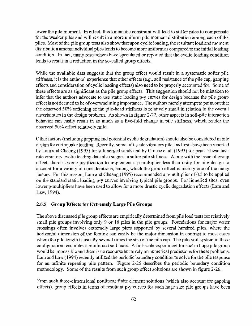
lower the pile moment. In effect, this kinematic constraint will lead to stiffer piles to compensatefor the weaker piles and will result in a more uniform pile moment distribution among each of thepiles. Most ofthe pile group tests also show that upon cyclic loading, the resultant load and momentdistribution among individual piles tends to become more uniform as compared to the initial loadingcondition. In fact, many researchers have speculated or reported that the cyclic loading conditiontends to result in a reduction in the so-called group effects.
While the available data suggests that the group effect would result in a systematic softer pilestiffness, it is the authors' experience that other effects (e.g., soil resistance ofthe pile cap, gappingeffects and consideration ofcyclic loading effects) also need to be properly accounted for. Some ofthese effects are as significant as the pile group effects. This suggestion should not be mistaken toinfer that the authors advocate to use static loading p-y curves for design because the pile groupeffect is not deemed to be ofoverwhelming importance. The authors merely attempt to point out thatthe observed 50% softening of the pile-head stiffness is relatively small in relation to the overalluncertainties in the design problem. As shown in figure 2-22, other aspects in soil-pile interactionbehavior can easily result in as much as a five-fold change in pile stiffness, which render theobserved 50% effect relatively mild.
Other factors (including gapping and potential cyclic degradation) should also be considered in piledesign for earthquake loading. Recently, some full-scale vibratory pile load tests have been reportedby Lam and Cheang (1995) for submerged sands and by Crouse et al. (1993) for peat. These fastrate vibratory cyclic loading data also suggest a softer pile stiffness. Along with the issue ofgroupeffect, there is some justification to implement a p-multiplier less than unity for pile design toaccount for a variety of considerations, among which the group effect is merely one of the manyfactors. For this reason, Lam and Cheang (1995) recommended a p-multiplier of 0.5 to be appliedon the standard static loading p-y curves involving typical pile groups. For liquefied sites, evenlower p-multipliers have been used to allow for a more drastic cyclic degradation effects (Lam andLaw, 1994).
2.6.5 Group Effects for Extremely Large Pile Groups
The above discussed pile group effects are empirically determined from pile load tests for relativelysmall pile groups involving only 9 or 16 piles in the pile groups. Foundations for major watercrossings often involves extremely large piers supported by several hundred piles, where thehorizontal dimension of the footing can easily be the major dimension in contrast to most caseswhere the pile length is usually several times the size of the pile cap. The pile-soil system in theseconfiguration resembles a reinforced soil mass. A full-scale experiment for such a huge pile groupwould be impossible and there is no recourse but to rely on numerical predictions for these problems.Lam and Law (1994) recently utilized the periodic boundary condition to solve for the pile responsefor an infinite repeating pile pattern. Figure 2-25 describes the periodic boundary conditionmethodology. Some ofthe results from such group effect solutions are shown in figure 2-26.
From such three-dimensional nonlinear finite element solutions (which also account for gappingeffects), group effects in terms of resultant p-y curves for such huge size pile groups have been
62

DEFORMEDMBSHSoil
Pile
rrrI1-
LI I1--1I Ir-;I I-r
_LI I
-~-l
I I-I- -;
I 1-r
II
_LIII-,I
__ LII
\
/ ) EqualDisplacementBoundary
~ -1 - 1 T r -r -1h3= lCfi- ~~- ~b
Soil DisplacementProfile
~
~
F-
G---
~
F
lcP- I) G--l- - - ~ - - - - -
0)-----f --,. -------Y I) G-
~ -"", Periodic Boundary Condition
\ \ \ ~\
F
~
G--
G-
~
0-
/Pile
~
0\w
Figure 2-25 3-D FE Analysis using Periodic Boundary Condition for Infinite Pile Groups

~~
III
~5a.
soil(clastic-plasticcoostitutive model)
pi,___---(
Y
Pte==y
~te
IPC=y
pileEI laleraJ soil SUpr"
}DonJinear i>"Y
-'\I\r-~
----lOf---
L-------.
BMCOL analysis (Slick Model)
f-
Shear _
fIIIu
'8'60..
1.21.0
3D FEM: lJDIs3
: I.lD-6
0.8
3D
0,60.4
3D FEM: 1JIP24
0,0
--J--~l~--ll:-~II I Io-r- I
' 02
I II II-l /1 / 71so r,
BMCOL: i>"multipliet""'I.Oy-multiplier=l.O
BMCOL: i>"multiplicr-<l.75y-multiplier-2.0
BMCqL: i>"multiplicr=O.5I II / y-mulupller-4.0
200 I I I 7 Iv I I '7 I I
ISO+- I j4' V \lfZ \ I I---~
l~~ 100_1 1/ 1-/ A I I I II-
~0..
~
Pll..E TOP DISPLACEMENT (ft) FEM analysis (3D)
Figure 2-26 Results of Group Effects at 3 Spacings for Infinite Pile Group

studied. From the limited number of solutions, the authors found that for a pile center-to-centerspacing of3 diameters, it is necessary to soften the elastic branch of the p-y curves (by using a ymultiplier larger than unity) in conjunction with the 0.5 p-multiplier. For the 3-diameter center-tocenter spacing, y-multiplier values up to 4 have been used in past projects.
2.6.6 Pile Design in Liquefiable Soils
Another major area of advances in the pile design problem from research programs funded byFHWA/NCEER is in the pile design for liquefiable soils. As discussed earlier, pile design inliquefiable soils involves consideration for two load cases: (1) the load case associated withstructural loading (e.g., from inertial load induced by the earthquake), and (2) an additional load casearising from earth pressure loading on the embedded piles associated with the lateral ground spreadproblem. Figure 2-27 schematically illustrates the two loading mechanisms. These two load casescould occur simultaneously during the earthquake, and a rather complicated time-history analysiswould be required to account for this problem involving modeling the overall bridge structure andfoundation in a total solution analysis approach, coupled with solutions ofthe ground displacement(including permanent displacement) problem. However, such an analysis approach would be highlycomplex at the present time and would require teaming experts in the fields ofstructural engineeringand soil-structure interaction. To avoid such complexity, it might be appropriate to uncouple the twoload cases into separate analyses. Some comments are provided in the foregoing sections to addressdesign issues for the two load cases.
2.6.6.1 Design for Structural Loading
The overall analytical procedure to support design for structural loading would essentially be thesame as the previously discussed procedures. However, the choice ofp-y characteristics or the linearsubgrade modulus must properly consider liquefaction effects of the soil mass in the vicinity ofthepile, with more emphasis given to the significant soil-pile interaction zone at shallow depths adjacentto the structure.
A number of studies have recently been conducted to study the p-y curve characteristics ofliquefying soils. The liquefaction phenomena is related to the pore pressure build-up process andits effects on the fundamental stress-strain characteristics of the soil mass. There are two porepressure generation mechanisms that need to be considered as discussed below.
Pore-Pressure From Local Soil-Pile Interaction
The piles would be loaded by the structure which would induce a stress field in the soil mass locallyaround the pile at the soil-pile interaction zone adjacent to the structure. Some full-scale vibratorypile load test data has been presented by Lam and Cheang (1995); they found that p-y response underfast-rate vibratory loading could result in a softer overall pile-soil stiffness as compared to the slowstatic monotonic loading (the basis ofthe static p-y curve). Hence, Lam and Cheang recommendedthat a p-multiplier less than unity should be applied to the static loading p-y curves ofthese soils toallow for the cyclic loading condition in earthquake design.
65

A similar observation has been made by Crouse et al. (1993) who presented similar vibratory pileload test data for a peat site. Various mechanisms, including a dynamic gapping phenomenon havebeen postulated by Crouse et al. to explain the softening ofthe pile stiffness under fast rate vibratoryloading, as compared to the parallel slow cyclic loading tests. This softening effect, related to sucha gapping phenomenon sustained by the faster vibratory rate, was rather drastic at the smalldeflection range (a p-multiplier as low as 0.2 was observed at less than 0.3 inch deflection).However, it is speculated that such a dynamic gap might not be sustained at the larger deflectionlevel ofdesign interest. Nevertheless, there is ample evidence from such vibratory loading test datato recommend a softer (as compared to the monotonic static pile load tests) pile stiffness forearthquake design. In conjunction with the pile group effect issue, a p-multiplier of 0.5 applied tothe static p-y curve has been adopted for typical design applications.
Pore Pressure/rom Global Free-Field Site Response
The component of pore pressure response related to cyclic loading on the soil from free-field siteresponse has been investigated by centrifuge model tests first conducted Dobry and others at theRenselaer Polytechnic Institute. A similar major centrifuge model test program is also currentlyunder way at the University of California at Davis. These experiments were conducted (l) toevaluate the p-y characteristics of soil liquefied because ofa global pore-pressure mechanism, and(2) to understand the loading mechanism on the pile from lateral spread ofliquefied soils (see figure6-27b).
Figure 2-28 presents a plot obtained from centrifuge experiments to measure p-y curvecharacteristics ofliquefied soils (Liu and Dobry, 1995). A varying degree of pore pressure is firstinduced in the saturated sand by subjecting the soil to a free-field shaking loading condition, andthen a cyclic pile load test is immediately conducted prior to dissipation ofpore pressure to measurethe p-y curves for the liquefied sand. These curves are then compared to the nonliquefied p-y curvesto develop the scaling factor (degradation coefficient in figure 2-28) for static p-y curves for sandsat different pore pressure conditions. In a design problem, upon determination ofthe pore pressureassociated with free-field site response analysis, the figure can be used to estimate the scaling factorto be applied to the initial undegraded p-y curves to develop the p-y curves for the liquefied soils.
It can be seen from figure 2-28 that for a complete liquefied soil condition, the residual p-y curvewould be about 0.1 of the initial static p-y curves. This figure illustrates the state of the soilcondition after free-field liquefaction at the first cycle of pile loading, and hence degradation fromlocal soil-pile cyclic loading has not been accounted for. As discussed earlier, in addition to theglobal free-field degradation effect, cyclic loading on the pile from the structure would induceanother component of degradation to the soil mass locally around the pile. As discussed earlier, ap-multiplier of0.5 is recommended to account for such local soil-pile interaction effects. As can beseen in figure 2-28, a degradation coefficient of 0.5 corresponds to about 70% free-field porepressure. It can be concluded that for denser soils which would have a free-field pore pressurebelow 70% of the effective overburden, degradation on the p-y curve would be controlled by thelocal soil-pile interaction mechanism, and the default 0.5 p-multiplier on the p-y curve would apply.At higher pore pressure ratios (above 70% of initial effective overburden) corresponding to almostinitial liquefaction, degradation effects will be controlled by free-field pore pressure phenomena and
66
Earth PressureActing on Pilefroxo. Drag Forcesinduced froxo.Lateral GroundSpread ofLiquefiedSoils
Ground Displa.ce=entProfile
Restraining Forcefros:n Bridge St:ru=
...
Earth PressureR.cactingSt:ru=Load
Earth Pressure
~_--,._..,Ac7= Pile Cop
Force..
.... Earth PressureR.cact:ingDrag Force fros:nGround Spread
(a) Soil-Pile I::nteraetion Probl=frO:c:::l. St:ru= Loading
(b) Soil-Pile I::n~onProbl=fros:n Earth Pressure Loadingassociated __i:tb. Ground Displa.cC:c:::l.ent
Figure 2-27 Loading Mechanism in Soil-Pile Interaction Problem
67

1.0
0.8~u~
l:: 0.6 •Q).~
0.~--Q) 0.40u
0.2
•0.0·
0 20 40 60 80 100
Pore pressure ratio, ru (%)
Figure 2-28 Degradation Coefficient Cu versus Pore-Pressure Ratio from Liu and Dobry
68

the degradation coefficient versus pore pressure ratio shown in figure 2-28 can be used to developthe p-multiplier for pile design.
The centrifuge experiment discussed above was conducted on loose, cleanNevada sand with relativedensity Dr of40%. A residual p-y strength of0.1 can be deemed appropriate for a loose, clean sandsoil condition. For other denser sand, or sand with cohesive fines and silts, the residual p-y strengthcould be higher than 0.1. Some evidence of a higher residual strength of liquefied soil has beenobserved in parallel centrifuge experiments from the University ofCalifomia at Davis. P-multipliersfor liquefied soil as high as 0.25 have been reported.
Deep Liquefiedp-y Curves
So far, Reese p-y curve criteria for sand have been the basis for the benchmark p-y curves. However,Reese p-y curve criteria arose from empirical pile load tests which only yield soil-pile interactiondata at very shallow depths (the upper five pile diameters), and the formulation of p-y curves atdeeper depths are largely founded on theoretical grounds. P-y stiffness and strength for sands areassumed to be directly proportional to the effective overburden pressure, and hence increase linearlywith depth in saturated soil. Lam and Cheang's (1995) observation ofdeeper p-y curves suggestedthat such theory might overpredict the p-y curve stiffness at depth.
A similar observation has been made by Chaudhuri (1998) who suggested that soil-pile interactionis a largely undrained loading process and one needs to appreciate the stress-strain characteristicsin the undrained loading condition. He utilized a critical-state soil mechanics constitutive model toinvestigate undrained behavior of sands and concluded that the Reese sand p-y criteria might leadto very stiffp-y curves at depth. This aspect led to some problem on the criteria ofresidual degradedstrength at 0.1 of the static p-y curve at large depths, which would influence the results of soil-pileinteraction analysis associated with lateral ground spread problems, where the soil-pile interactionzone could become much more deep-seated than the structural loading problem. To circumvent thisproblem, following adjustments on liquefied p-y curves are suggested.
In addition to the 0.1 initial p-y criteria, Dobry and his colleagues (Abdoun, 1997) have attemptedto backfit typical undrained shear strength values of liquefied soils from the measured drag appliedon piles by lateral spreading centrifuge tests. They found that a liquefied loose sand typically hasan undrained shear strength of 21 psf. The ultimate passive pressure on the pile (i.e. Pu/t) has beenfound to increase from 3cD at mudline to 9cD at depth (Matlock, 1970). Therefore, Pull valuecorresponding to an undrained shear strength of 21 psf could vary from 63 psf to 189 psf.
A brief summary ofthe discussion on treatment ofp-y curves for liquefied sands is provided herein:
(1) A p-multiplier of 0.5 can be set for unliquefied p-y curves to reflect degradation from localsoil-pile interaction or softening due to pile group effects.
(2) Free-field site response analyses should then be conducted to evaluate the free-field porepressure amplitude and possibly to conclude whether the site has lateral spread or slopeinstability potential and to solve for the mode and the magnitude of ground deformation.
69

(3) For a free-field pore pressure higher than 70%, the degradation coefficient shown in figure2-28 can be used to establish the p-y curve characteristics of the liquefied (or virtuallyliquefied) soils.
(4) The resultant Pull can be checked against the value of9cD, where c is the undrained shearstrength postulated for liquefied soils equal to 21 psf and D is the pile diameter. If the Pull
from Step (3) is higher than this limiting value, the limiting value should be used to developthe p-y curves for the liquefied soil instead.
The above described p-y curve procedures can be used to conduct soil-pile interaction analyses fordesign against the structural loading conditions in a conventional load-deformation analysisframework. However, it is stressed that the above given residual shear strength was measured fromonly one experiment, and caution should be exercised in using this value. Residual shear strengthsof liquefied sand depend on factors such as void ratio and grain size characteristics. A wide rangeof values has been backcalculated from case studies (e.g., Seed and Harder, 1991).
The use of the discussed p-y curves in pile integrity analysis associated with the lateral groundspread problem requires some additional considerations as discussed below.
2.6.6.2 Design Issues Related to Lateral Ground Spread
As discussed above, a major liquefaction design issue is related to design for the lateral groundspread problem. When this load case is uncoupled with the dynamic response ofthe superstructure,the design for this load case involves the following elements for consideration:
(1) Analysis to predict the mode and amplitude of potential ground spread displacement. Anumber of research studies is actively underway on this subject. Dobry's centrifugeexperiment shows two typical generic modes of ground displacement profiles as shown infigure 2-29. Figure 2-29a represents a two-layer soil profile of liquefied soil above theunderlying unliquefied soil. Figure 2-29b presents a three-layer profile of a liquefied soillayer in between unliquefied soils. The upper unliquefied layer might represent a stifferupper layer or very often represents a soil layer above the ground water table, whichtherefore is not liquefiable. Recent studies conducted at RPI and Cornell University arrivedat the following conclusion; the maximum pile moment is usually at the bottom of theliquefied soil layer, where an abrupt change in the slope of relative ground displacementwould occur.
Most current lateral ground spread procedures concentrate on predicting the basic case offree-field ground displacement without considering of the reinforcing effects of theconstructed structure. It is found that in some cases, such as the configuration in figure2-29b, the reinforcing effect of the piles would lead to a significant reduction in theamplitude ofpermanent ground displacement. Figure 2-29b shows that ifthe liquefied layeris relatively thin, the pile would act as a fixed-fixed beam and additional stiffness from thepinning effect ofthe pile would add on the residual shear strength ofthe liquefied soil layer.
70

This additional shear strength from pile pinning effect can often be as much or more than thein-situ shear strength ofthe weak soil layer, and hence its effect must be accounted for in theassessment of the amplitude of ground displacements.
(2) Soil-pile load-deformation analysis. This analysis can be conducted by establishing theproper pile soil model (i.e., choice ofproper pile E1 and p-y springs including simulating theproper p-y effect for liquefied soils) and the ground displacement pattern from the analysisin item (1) can be used to prescribe offsets on the p-y curves, and the pile can be allowed todeform to conform with the kinematic effect of the prescribed ground displacement. Theresultant solution would yield a deformation pattern and shear and bending moments on thepile which can be used to evaluate the survivability of the pile for the postulated groundmovement. Some comments on some aspects of p-y curve in the context of the describedanalyses are discussed below.
Pile Survivability for the Two-Layer Soil Configuration
For the configuration shown in figure 2-29a, the ultimate pressure capacity of liquefied soilsdiscussed above can be used as input to the kinematic pseudostatic soil-pile interaction in lateralspreading analyses. However, it is cautioned that the resultant pile moment should only be regardedas the lower-bound pile moment because in the case of kinematic soil-pile-interaction analysis, asofter p-y curve actually can lead to unconservative assessment of pile moment for a specifiedground displacement. The above discussed p-y curves for liquefied soils (i.e., 0.1 static p-y curvesand residual undrained shear strength of21 pst) represents the minimum residual strength only. Asthe soil transforms from the stronger unliquefied state to the ultimately liquefied state, there is atransition of stiffer soil to softer soil and at some intermediate stage, the pile can experiencemoments higher than the ultimate steady state condition. Figure 2-30 was extracted from Dobry'swork to illustrate this aspect using fully degraded p-y curves. As shown in the figure, the pilemoment is higher at a smaller amplitude of permanent ground displacement (at a time of about 17sec) than in the ultimate condition (at time of about 32 sec).
Chaudhuri (1998) utilized critical state soil mechanics theory to predict the transition ofthe state ofp-y curves and simulated the described behavior. However, the procedure utilized in the studyinvolved rather sophisticated constitutive modeling and corresponding soil sampling and testingprograms to develop the required soil parameters and would be too complex for practical design.Itmay be possible, at the current state-of-understanding to conduct the kinematic soil-pile interactionanalyses to determine the pile moment at the steady state residual soil strength condition. Anadditional kinematic soil-pile interaction analysis can be conducted using initial static p-y curves(i.e., the stiffest p-y curve scenario). The two bounding solutions can be used to set the upper andlower-bound pile moment to facilitate the application of engineering judgement in design decisionprocess.
71

Pile Survivability for the Three-Layer Soil Configuration
For the configuration shown in figure 2-29b, the kinematic soil-pile interaction analysis involvesformulating the appropriate p-y curves for the upper crust of unliquefied soil layer. In most cases,the large cross-sectional area of the pile cap would account for most of the dragged forcesconstituting the loading mechanism on the underlying piles. The procedure to develop the passivepressure capacity acting on the pile cap discussed in Section 2.5 can provide the upper-bound dragforce on the underlying foundation system. This is an upper bound loading scenario because the soilcapacity of the upper crust could be eroded as it sits on liquefied soils.
Berrill et al. (1997) reported an actual case history of physically observed lateral ground spreadagainst a pier footing and concluded from backfitting that the passive earth pressure in the uppercrust would be approximately equal to that predicted by the Rankine earth pressure theory (a passivepressure coefficient (Kp) of about 1 for the reported soil friction angle of 44° and cohesion of200 pst). This back-calculated passive pressure capacity is very low compared to the log-spiralpassive pressure theory discussed in Section 2.5 (the ratio of Rankine's earth pressure capacity tothe log-spiral capacity would be less than 0.1). This case history may suggest an adjustment factorof as small as 0.1 which can be applied to the log-spiral earth pressure capacity (i.e., the originalstatic passive pressure capacity of the pile cap prior to liquefaction). For the kinematic soil-pileinteraction shown in figure 2-29b, Berrill also reported that the buttressing effect ofthe bridge deckwhich opposes the drag force acting on the pile cap also provided some measure of resistance tooppose the lateral spread loading condition imposed on the pile cap.
Among the two lateral spread configurations shown in figure 2-29a and 2-29b, it appears that thecondition shown in figure 2-29a actually might be rather benign because the liquefied soils tends tomerely flow around the foundation system, and the dragged force on the foundation system couldbe rather small. The configuration shown in figure 2-29b could be more hazardous and has been thecause of pile damage or even collapse of bridge structures since this configuration has resulted invery high curvature in the pile. However, the high pile stresses also often lead to significantreinforcing effects of the pile which could significantly reduce the amplitude of grounddisplacement. It is felt that this latter configuration involves more complex soil-pile interactionissues that are more germane for design consideration and more effort is needed to fine-tune thedesign problem related to this three-layer lateral spread and soil-pile interaction problem.
72

PourntieJ. HingeZon..
UNLIQUEFIEDLAYER.
(b) Lau=a.l Spread Loading Problc::=.for Liquefied Layer above Unliquefied Layer
.. Rest:ra.ining Foree:fro:c::L Bridge Struc1:Ure
F-f--- Earth PressureReacting LateralSpread Loading
. UNLIQUEFIEDLAYER.
Drag Force frOID.
Ground Spread
(b) La=raJ. Sprea.cl Loading Problc::=.for Unliquefied Layer above Liquefied Layer
Figure 2-29 Two Generic Soil Conditions for Lateral Spread Pile Loading Problem
73

400.25m
20
0
-20
-40
0 10 20 30 40
40' . .:. ...,........
2.0m20
0,,-...
E -20I -40z~......... 0 10 20 30 40-.J
C 100Q)
E 80 4.0m0 60~
4020
0
0 10 20 30 40140120100 5.75m
80604020
0
0 10 20 30 40
Time (sec)
Figure 2-30 Bending Moment from Centrifuge Lateral Spread Loading Experiment
74
SECTION 3MODELING OF DRILLED SHAFTS
3.1 Introduction
Drilled shafts are large diameter piles that are used to support high axial loads and overturningmoments. They are constructed by drilling/auguring a hole in the ground which may be lined tosupport the sides ofthe excavation. Upon completion ofdrilling, a reinforcement cage is placed andthe cavity is filled with concrete. Because oftheir relatively disturbance-free installation procedureand high load carrying capacity, drilled shafts are often advantageous over conventional smalldiameter piles. Increased use of this type offoundation can be found for supporting different typesofstructures such as bridges, transmission towers, and telephone poles. In this section ofthe report,discussion is focused mainly on seismic design aspects of drilled shaft foundations for bridgestructures subjected to lateral loading.
The analysis and design ofdrilled shafts for the most part are similar to those ofconventional-drivenpiles. Important differences, however, exist due to installation procedure, larger diameter, and smalllength to diameter ratio compared to typical smaller driven piles. One major difference is thatbecause of these factors, drilled shaft analysis requires some additional considerations, which arelater discussed in this section. Also, for bridge structures, the structural arrangement ofdrilled shaftfoundations can be different from conventional structural arrangement. As mentioned before, mostbridges on drilled shafts are pile extension type structures (Figure 1-1b). The lateral loads that acton the bridge deck are reacted by the induced shear and bending moment on the drilled shafts. Theoverall bridge response is relatively insensitive to axial pile response in contrast to pile footingsdiscussed in Section 2.
In developing seismic design guidelines for drilled shaft foundations as well as other types offoundations, various issues related to modeling ofactual foundation behavior should be investigated.The effect ofmodeling assumptions on the design displacement and force demand on the foundationshould be evaluated and the limitations should be identified. As mentioned earlier, the most widelyused method to analyze pile response under lateral load is by using a p-y model in which soil isreplaced by a series of nonlinear springs. A p-y model simply describes the force-displacementrelationship of a soil spring, in which p is the soil reaction force per unit length, and y is thecorresponding pile displacement. A number of p-y models have been proposed for different soilconditions. The two most commonly used p-y models are those proposed by Matlock (1970) for softclay and by Reese et al. (1974) for sand. P-y curves for other soil conditions, e.g., stiff clay, rock,can also be found in the literature (e.g., Reese, 1986). The p-y models are essentially semi-empiricaland have been developed on the basis ofa limited number of full-scale lateral load tests on piles ofsmaller diameter, ranging from O.3m to 0.6m (12 to 24 in). To extrapolate p-y criteria to conditionsthat are different from the one from which these models were developed, requires some judgementand consideration. In fact, several studies (Davidson, 1982; Lam and Martin, 1986) indicated thatthe p-y models, which were developed from load tests on small diameter piles, might underestimatethe soil stiffness for larger diameter drilled shafts. The reasons for such variations are discussed, anda more rational method of estimating drilled shaft stiffness is proposed.
75

3.2 Seismic Design Procedure for Drilled Shafts
Unlike static loading, dynamic loads on a structure cannot be specified independent ofthe foundationbecause they are functions of the foundation stiffness characteristics as well as the structuraldynamics properties. It is important to recognize that foundations, being a part of the structuralsystem, influence and modify the overall dynamic response characteristics of the structure.Therefore, a realistic estimation of foundation stiffness and integrating it in the structural analysisis very important. In general, the foundation-soil system responds nonlinearly to the applied load.However, for practical purposes, the foundation is commonly represented as an equivalent linearsystem which is then incorporated in the analytical model. Structural designers and geotechnicalengineers should be aware of the modeling procedure of the foundation system and the inherentlimitations posed by the simplifying assumptions.
Seismic design ofbridge structures and foundations involves a two step procedure. In thefirst step,the geotechnical engineer estimates the soil-foundation stiffness based on the available informationon soil properties (e.g., drilling record, in-situ or laboratory test data) and the type of foundationsystem. The foundation stiffness is then incorporated in the structural model by the structuralengineer, who performs a structural analysis (e.g., modal analysis, time-history analysis) to estimateload and displacement demands on the foundation arising from the seismic ground motion. Becausethe actual foundation is replaced by an equivalent linear model, this first step of analysis might notyield any meaningful information regarding the force and moment distribution in the foundationsystem, especially at high seismic loads where overshoot of force above the foundation capacity isexpected. It should be noted that any overshoot offorce above capacity ofthe system is due largelyto the linear assumption in the analytical model. If a nonlinear load-deflection curve is used in aniterative nonlinear response analysis, the predicted load will be compatible to the input loaddeflection curve and the overshoot above the assumed capacity will be negligible. Therefore, theonly way to evaluate the integrity of the system would be to base it on the computed displacementdemand. A second analytical step is needed to calculate the force demand in the system (includingfoundation forces) realistically.
In the second step, the overall foundation system with the surrounding soil is modeled includingstructural nonlinearity to conduct a quasi-dynamic push over analysis of the bridge system todetermine the displacement level where structural yielding is initiated (i.e. to determine yielddisplacement) and how the load is distributed to structural elements at various load levels (includingthe design earthquake load level). On the basis ofthe analyses, foundation capacity (usually basedon the displacement level where there is no compromise on the vertical load capacity of the drilledshafts) is evaluated and compared to the displacement demand for the design earthquake foradequacy in structural integrity for earthquake performance. Each step is described and some oftheimportant issues involved in each step are discussed in the following subsections.
3.2.1 Step 1 : Modeling of Foundation Stiffness
According to the current state of practice, the response of drilled shaft foundations to externallyapplied lateral load and moments are analyzed by idealizing the soil as a series oflinear or nonlinear
76

springs. The force-displacement characteristics ofthe springs are defined by p-y relationships, andvarious procedures for developing p-y curves have been proposed by several authors. The mostcommonly used p-y formulations in practice are the ones based on procedures suggested by Reeseet al. (1974) for sand and Matlock (1970) for clay. Another popular method is the one recommendedby the American Petroleum Institute (API), which is essentially developed from the abovementioned methods. Although p-y relationships are semi-empirical in nature, they are found toprovide reasonably good prediction ofpile response. Another commonly used practice is to adopta linear approach, and to characterize the subgrade based on the recommended values ofcoefficientofsubgrade modulus by Terzaghi (1955). Lam et al. (1991) indicated that solutions based on linearsubgrade modulus theory can adequately represent pile stiffness. They presented design charts toestimate pile head stiffness for piles embedded in a subgrade with linearly increasing modulus. Thesubgrade modulus, EI" at a depth z is given as in eq. (2-3) and repeated herein for convenience,
(3-1)
in which/is the coefficient ofvariation in subgrade modulus with depth. Under elastic conditions,subgrade modulus can be related to the Young's modulus of soil. Based on closed form solution ofinfinitely long beam on an elastic foundation, Vesic(1961) showed that, when subgrade modulus isconstant (i.e., constant with depth), it can be related to soil Young's modulus (E,.oi/) as
Es = 0.65
12 4Esoi! D
EI(3-2)
where D is the width of the beam, E is the Young's modulus of pile, I is the moment of inertia of
beam, and vis the Poisson's ratio ofsoil. It must be noted here that eq. (2-6) is an approximate formof eq. (3-2).
As an alternative to subgrade modulus or p-y approach, some researchers ( e.g., Poulos and Davis,1980) developed solutions by idealizing the soil as an elastic continuum. A comprehensive summaryon this particular approach is presented by Pender (1993).
Once the pile response is estimated by one of these methods, pile stiffness can be represented inseveral ways. Three common methods are 1) coupled foundation stiffness matrix, 2) equivalentcantilever model, and 3) uncoupled base spring model. A brief description of these methods arepresented here. For more detailed discussion the reader is referred to the work by Lam and Martin(1986).
3.2.1.1 Coupled Foundation Stiffness Matrix
Among the three methods mentioned above, the most general method to represent the foundationstiffness is by the coupled foundation stiffness matrix. In this method, the stiffness ofa single pileis represented by a 6 x 6 matrix representing stiffnesses associated with all six degrees of freedomat the pile head as illustrated in figure 3-1. The common form ofthe stiffness matrix in the local pilecoordinate system is given in eq. (3-3),
77

(a) Drilled Shaft and Bridge Superstruetre with LocalPile Coordinate System
Kx 0 0 0 0 0Ky 0 0 0 Kyez
Kz 0 - Kzey 0Kpile = KOx 0 0
~KOy 0Cantilever
KOz
(b) Stiffness Matrix (c) Equivalent Cantilever (d) Uncoupled Springs
Figure 3-1 Pile Head Stiffness Representation78

Kx 0 0 0 0 0
K 0 0 0 Kyezy
Kz 0 -KZeY 0Kpile (3-3)
Kex 0 0
Key 0
Kez
in which the diagonal terms Kx• Ky, K=. Kex.Key. K(£ are stiffnesses corresponding to translational androtational degrees of freedom associated with x (local pile axis), y, and z axes, respectively. Theoff-diagonal terms represent coupling between two degrees of freedom. For a single vertical pile,the axial and torsional stiffnesses can be uncoupled from other degrees of freedom, and as a resultthe corresponding off-diagonal terms are zero. For a single pile embedded in a subgrade withlinearly increasing subgrade modulus, Es , the stiffness coefficients can be calculated from thesolutions presented by Lam et al. (1991). For piles in layered soils, the pile head stiffness matrixcan be computed by conducting static condensation such that all degrees of freedom below the pilecap are eliminated (Bryant, 1977).
For piles of flexural stiffness Elp embedded in linearly increasing subgrade modulus, the stiffnessmatrix at the pile head (grade elevation) was calculated by Lam et al. (1991) and is given by
1.06
[Ky Kyez] ;1,3
K = = Els m K pY ez sym
0.98
;e1.48
A
(3-4)
(3-5)
in which A is the characteristic length of the pile, and can be estimated as
A = ~ E;The procedure for estimating the stiffness matrix for a single pile (along with simplified designcharts) and pile group has been described in detail in the previous sections.
3.2.1.2 Equivalent Cantilever Beam
In the equivalent cantilever method, the foundation is replaced by a cantilever beam that has astiffness equivalent to that of the pile and the surrounding soil. This is represented schematicallyin figure 3-1 c. The CaliforniaDepartment ofTransportation design manual (Caltrans,1990) suggeststwo procedures for estimating the equivalent cantilever length for the pile. The first one is a
79

simplified procedure, in which equivalent pile length is estimated based on the SPT blow count ofthe soil stratum as shown in figures 3-2 and 3-3. In the other method, which is termed as the'rigorous' method, the equivalent length is estimated by matching the pile stiffness (from a Caltransin-house pile-soil system load-deflection solution) with the stiffness ofa cantilever beam by equatingdisplacements and rotations. The equivalent cantilever can also be estimated by equating themaximum moment in the pile. The estimated length, in that case, may be different. The choice ofthe method to determine the equivalent cantilever model depends on the intended applications. Forseismic design, the equivalent cantilever model is normally used to account for foundationstiffnesses in a global dynamic response analysis. As discussed earlier, after the displacementdemand is established, a second step pseudo static pushover analysis is needed for capacityevaluation. The state-of-practice is to represent the soils by p-y curves in this second step approach.The equivalent cantilever model is generally considered to be too crude in the second step in whichforce amplitude and corresponding distribution are evaluated.
It is possible to calculate equivalent length of the cantilever beam by equating the terms ofthe pilehead stiffness matrix with those in the stiffness matrix of a cantilever beam. The correspondingstiffness matrix of a cantilever beam of length Lc and flexural stiffness, Elc' is given by
12 6-
L 3 L 2
Keantilever = £1e e (3-6)
e4
symL e
The stiffness matrix ofthe soil pile system (shown in eq. 3-3) can be approximated by an equivalentcantilever model by choosing the appropriate Elc and equivalent cantilever length Lc . It is obviousthat only two cantilever model parameters are not sufficient to satisfy all three stiffness coefficients(two diagonal stiffness and one cross-coupling stiffness coefficients) in eq. (3-3). The generalapproach is to match the diagonal stiffness terms which leads to the following cantilever modelparameters:
£1 = 0.757£1e p
(3-7)
(3-8)
The basis of matching the diagonal stiffness coefficient in the above equivalent cantilever modelappears generally sound, especially for a pile extension type configuration (shown in figure 1-1b).
For a pile footing type configuration (figure l-la), the rotational stiffness ofthe pile group tends tobe dominated by the axial pile stiffness as compared to the stiffness contribution from the bendingstiffness ofindividual piles. Therefore it might be possible to choose the equivalent cantilever modelsolely to match the lateral force versus deflection equation (i.e. the first of eq. 3-4 by matching thetranslational and the cross-coupling stiffness term) resulting in the following cantilever model. Thisapproach can lead to a more appropriate lateral stiffness for a wider range of pile head boundary(fixed and free head) conditions.
80

50\0 20 30 40
Standard Penetration Index - N, Blows/ft.
I Depth to Point of Effective Fixity -
Iin
CLAYI Ie RIC Piles 4 -10 ft. Dia.-I
Id"'"="-11Column Length=20-100ft, E=468,OOO ksf
II (Using. Reeses Approach, August, 1980)
4' ~ \.No x 010.
McBride I Maroney 2/85
~~\~"- I I8'~~
.~ IIO'Il~
"\~~ It-- I I
"---- - I-- - ' II
I
Very II
Verl I I.Soft . Soft Stiff Stif Hard
I I I.
I ,
\0
8>-.-x
u:a:l> 6.-u~--w0-o CIl 4
Z~a:l
E0
Cl- 20....a:l
..0E::lZ
1,-_O_-_~5_l...1~_-_1-I-1__1_-_2__.l- 2_-_4__14-6 Shear Strength, ksf I
1 kip = 4.45 kN1 in=25.4mm1 ft= 0.305 m
Figure 3-2 SPT Blowcount vs. Cantilever Length of Pile in Sand (After Caltrans, 1990)
81

d.l 5><.)
d.l--UJ
~
xi:i:
7.,.-----~----~-r_-----------------..,
Depth to Point of Effective Fixity
in
SAND6+-----+----1-~p;=============j-h RIC Piles, 4-10 ft. Dia.
~.I,C
:£fColumn Length: 20 -100 ft., E: 468,000 ksfC
t(Using Reeses Approach, August, 1980)
No x Die.Mc8ride/Maroney 2/85
VeryLoose Loose
SlightlyCompact Compact Dense I
602+-----...;.Ji.-.-----+! 1!--__---;..1 ......lI ---1
o 10 20 30 40 50
Standard Penetration Index - N 1 Blows/ft.
10-28 128 -30
1 kip = 4.45 kN1 in=25.4mm1 ft = 0.305 m
30-36 I 36-41 TA~prOXimate e II In degrees
Figure 3-3 SPT Blowcount vs. Cantilever Length of Pile in Clay (After Caltrans, 1990)
82

L e = 1.85.-1. (3-9)
(3-10)
When equivalent cantilever length is determined by matching displacements or stiffness, it representsthe foundation stiffness properly. However, the calculated shear and bending moments in thecantilever may not bear any relevance to those in the actual pile. Therefore, this particular modelingapproach is only suitable for the first step in the design process to represent foundation stiffness ina global dynamic response analysis ofthe bridge structure. To calculate pile forces, it is necessaryto go through the second step, where the complete pile with the surrounding soil is modeled.
3.2.1.3 Uncoupled Foundation Springs
As illustrated in figure 3-1d, the third method of characterizing pile stiffness involves replacementofthe pile by two springs, one representing the translational and the other representing the rotationalstiffness. In this particular method, the cross-coupling between lateral and rotational movement isnot maintained. For deep foundations, especially for a pile extension, the cross-coupling betweenlateral and rotational foundation stiffness are significant, and therefore, an uncoupled foundationspring model would not be appropriate. Such a model should be restricted for shallow foundations(i.e. spread footings) or pile footing type configuration for smaller piles.
3.2.1.4 Foundation Nonlinearity
The lateral load-deflection response ofa drilled shaft with a nonlinear p-y curve representation, butwith a linear bending stiffness (EI) assumption was previously shown in figure 2-1. As discussedpreviously, this type of nonlinear soil pile interaction analyses has become the state-of-practice inthe Step 2 nonlinear pushover design process for capacity determination. Such analysis usingnonlinear p-y curves can also be used to derive the appropriate foundation stiffness matrix in Step1. However, use of such nonlinear foundation load-deflection solutions to develop linearfoundation stiffness matrices may lead to erroneous solutions if proper precautions are not taken.Some words of cautions are provided below in this aspect.
(l) Suitable Stiffness Matrix. It is important to recognize that a foundation stiffness matriximplies a linear pile and soil system. For example, each point in the nonlinear loaddeflection curve in figure 2-1 implies a different tangent stiffness matrix with its own threestiffness coefficients. The foundation stiffness matrix must be positive definite andsymmetric for practical analyses and design procedures. The way to ensure that theappropriate stiffness matrix can be developed from pushover analysis would be to firstdevelop equivalent linear soil-springs (suitable to the loading condition) compatible with thesecant modulus fitted through the p-y curves at the appropriate deflection values.Subsequent load-deflection analyses can be conducted for the linearized soil spring modelto solve for the stiffness matrix coefficients. So long as the pile and soil system has beenlinearized, a unique positive definite and symmetric stiffness matrix can be obtained
83
irrespective ofthe loading condition used for the pushover analysis. One way to ensure thatthe stiffness matrix is positive definite is to invert the stiffness matrix for the compliancematrix and check that the diagonal terms in the compliance matrix are all positive-real.
(2) Linearization ofNonlinear Load-Deflection Curves. A nonlinear load-deflection solutionimplies that the stiffness is dependent on the deformation and corresponding load amplitudes.
Unlike structural properties, which typically have reasonably well defined elastic stiffnesses,soils are intrinsically nonlinear, starting from extremely small load levels. For this reason,the choice of an equivalent linear soil modulus to develop foundation stiffness involvesnumerous complexity and uncertainties. In recent years the trend has been to base it on morecomplicated finite-element analyses using shear wave velocity data. If soil modulus basedon shear wave velocity data are used, they must be adjusted by extremely small factors(typically much smaller than those arising from free field wave propagation analyses suchas below 0.1, because the soil strain is usually an order ofmagnitude higher under foundationload as compared to wave propagation problems). It must be noted that strain compatiblesoil modulus determined from a I-D site response analysis would only be valid for I-D shearbeam configurations. This approach is typically used where equivalent soil modulus ratioversus shear strain relationships are utilized. Therefore, it cannot be used to establish straincompatible scaling factors for rather complicated 3-D soil-pile configurations which requiresrigorous 6-D stress-strain (constitutive) soil modeling. This method is not only complicatedbut also is not well proven for practical applications. For these reasons, the merits of aninherently complex finite element soil-structure interaction approach will be veryquestionable. Traditionally, empirical load test data (either Terzaghi's subgrade theory orp-y curves) formed the basis for stiffness evaluation in foundation design which has theproblem that they are mostly evaluated from slow rate loading conditions and might notcapture some aspects of dynamic effects. Most bridges are long period structures. Thediscussed foundation dynamic effects would be small as compared to the inertia forces ofthesuperstructure. The traditional p-y approach is simpler to use and also has been proven overits long history of applications.
Any nonlinear procedure theoretically requires an iterative process to ensure that the stiffnessmatrix is compatible to the assumed deflection level. As shown in figure 2-1, a secantstiffness at peak load/deflection would represent the lower bound stiffness occurring onlyat an infinitesimal duration in time during peak earthquake load. Such a stiffness might betoo soft to be representative for the overall duration ofthe earthquake. A secant stiffness ata smaller deflection might be a better choice to serve as the effective foundation stiffnessrepresentative for a longer time frame over the duration of the earthquake. In equivalentlinear site response analyses, Idriss and Sun (1992) proposed to establish the equivalentsecant soil modulus at an effective strain value equal to the peak strain multiplied by ascaling factor n = (Mw - 1)/10 where Mw is the earthquake magnitude (Moment magnitude).The above recommendation by Idriss and Sun, or simply establishing a secant foundationstiffness at 0.5 to 0.65 of peak deflection, would provide a better basis for developingfoundation stiffness than the lower bound stiffness at peak deflection.
84

(3)
(4)
Inherent Limitation. Various researchers (Miranda, 1991) have concluded that solutionsfrom linear response analysis generally give reasonable peak displacement predictions(referred to as equal displacement principle for long period systems). However, as shownin figure 2-1, a secant stiffness at below peak deflection will always overshoot the predictedload at the peak deflection for a typical nonlinear load-deflection curve. The dilemma is thata secant stiffness at below the peak load should be used in order to rationally capture thestiffness characteristics which in turn forms the basis to predict the proper level of peakdisplacement, but it would automatically overshoot the predicted load. This is the reasonthat a pseudo-static nonlinear pushover analysis is needed in a subsequent Step-2 to accountfor forces corresponding to the displacement demand predicted in Step-I. These inherentlimitations in a linear response analysis imply that a nonlinear dynamic response analysis isneeded to solve for both forces and displacement simultaneously in a one-step analysis fora system that has significant inherent nonlinearities (both material and geometricnonlinearity).
Significance of Foundation Stiffness. For most bridges supported by drilled shafts or pile.;
extensions, the compliance of the foundation is small compared to the compliance of theunsupported column. For this and the above discussed complexities and uncertainties infoundation behavior, a more simplistic linear approach to incorporate foundation stiffnessin the first step dynamic response analysis has many merits and is recommended for generalapplication. The recommendation is intended to minimize errors commonly associated withmore complicated approaches. The linear approach includes the use of Terzaghi's linearsubgrade reaction to account for soil stiffness in conjunction with an equivalent cantilevermodel to account for foundation stiffness.
3.2.1.5 Foundation Geometry
When the foundation system is replaced by any ofthe methods described in the previous subsection,it is an idealized representation of the actual system which gives a measure of foundation stiffness.Two foundation systems may have comparable stiffness, but the load supporting mechanism maybe completely different. Consider, for example, the pile group and the pile extension in figures 3-4aand b. The free-body diagrams of the two systems are shown in figures 3-4c and d, respectively.In the case of a pile group, the overturning moment is resisted by the axial stiffness of individualpiles, and the contribution of rotational stiffness of individual piles is relatively small for smalldiameter piles. Similarly, the torsional moment on the pile group is resisted by the lateral stiffnessof individual piles. For pile groups, therefore, coupling exists between axial displacement andoverturning rotation. On the other hand, in the case of a pile extension, the lateral load andoverturning moment are resisted by the lateral stiffness ofthe pile shaft alone. Similarly torsionalmoment is resisted by only the torsional stiffness of the single pile.
In addition, for the pile group, the pile cap contributes to the foundation stiffness due to lateral soilresistance on the bottom and sides of the pile cap. The contribution from the pile cap stiffness maybe significant when it is embedded in dense soil.
85

~ Bridge Superstructure Bridge Superstructure
I I Pile Cap
Piles/Drilled Shaft
(a) Pile Cap Configuration
Drilled Shaft
(b) Pile Extension
(c) Free Body Diagram for Pile Cap (d) Free Body Diagram For Pile Extension
Figure 3-4 Pile Configuration and Load Resistance Mechanism
86

3.2.1.6 Boundary Conditions
The boundary condition at the pile head has a significant effect on pile response and, therefore, onthe estimated pile head stiffness. When piles are connected to a rigid pile cap, the condition at thepile head depends on the reinforcement connection detail. The lateral stiffness can increase by afactor of2 to 3 as the pile head fixity changes from a free (pinned) to a fixed head condition. Formoment-resisting connections, the boundary condition at the pile head may be considered to be fixedagainst rotation, but free to translate. Figure 3-5 shows the influence of the boundary condition onpile response. In this figure pile head displacements and maximum pile moments are plotted for twodifferent boundary conditions, completely free and fixed against rotation only. The plots indicatethat, pile head displacement is strongly influenced by the boundary condition at the pile head,whereas the maximum calculated moments do not change significantly. Although the maximummoment for two conditions are comparable as shown in figure 3-5, the distribution of bendingmoment in these two cases are quite different. For the fixed head condition, the maximum negativemoment occurs at the pile head, whereas for the free head condition the maximum positive momentoccurs at depth below the ground surface. In reality the pile head condition is usually neither freenor fixed. A possible way to model the pile head condition would be to represent the joint by amoment-resisting rotational spring. As an example, the same pile is modeled with a rotation springat the head with a rotational stiffness of 1.1x10⁵ kN-m/rad. The calculated pile head displacementsand maximum pile moments for this condition are also shown in figure 3-5. While the fixed and freehead conditions present the upper and lower bound for pile head displacement ( therefore, lateralstiffness), the maximum pile moment for the partially restrained condition is not bounded by theabove conditions, but usually would be less than either the negative moment at the pile head for thefixed head case and less than the positive moment at depth for the free head case. The morebalanced and lower moment for a more realistic representation of the pile head fixity conditionusually can lead to more economical design and is an important design issue (both from a foundationstiffness as well as a force and moment assessment standpoint) that is often overlooked by designersand researchers.
For most piles, the boundary conditions at the pile tip do not affect the pile performance becausethey are sufficiently far from the structure and the piles can be considered as infinitely long piles
when the pile length is larger than 3 times the characteristics length A(eq. 3-5). For large diametershafts, it is important to check the pile length, especially for soft soil conditions, to determine theneed to include the pile tip's boundary conditions as compared to merely using closed form solutionsfor infinite beam solutions as shown in eq. (3-4). This will be further discussed in Section 3.2.2.4.
In many instances, concrete pavement or traffic barriers are constructed around drilled shafts at theground level. Unless a gap is maintained around the shaft, the pavement can provide lateral supportto the pile, which may in turn influence the pile head stiffness.
87

120
Partially Restrained
FreeT-~ ~ile Diameter = 1.2 m
Pile Modulus, E =2.4 x 10⁷ kPaPile Length, L =12 mSoil Friction Angle, 4J =34°Coef. of Subgrade Modulus, f =16 MN/m3
Reese's p-y Criteria
20 40 60 80 100
Pile Head Displacement (mm)
O~_...J.-_-'---~---'-----'-----'-----'-----'-----'-----'-----'------'
o
400
800
1200
-Z..:.:::----
1200
"/
@W //
~Partially Restrained
//- ~/Z 800 Free..:.:::
---- /
~"'0 /
rn /0 /
FixedY-1 /
/rn /'- /Q)..... 400 /rn /-1 / Pile Diameter =1.2 m
/ Pile Modulus, E =2.4 x 10⁷ kPa/ Pile Length, L =12 m
/ Soil Friction Angle, 4J =34°/
Coef. of SUbgrade Modulus, f =16 MN/mReese's p-y Criteria
00 1000 2000 3000
Max. Pile Moment (kN-m)
Figure 3-5 Boundary Condition and Pile Response
88

3.2.1.7 Other Considerations
Nonlinear Structural Behavior ofDrilled Shaft: The stress-strain response ofconcrete is not linearand the response deviates from a linear relationship at a relatively small strain. Because the elasticmodulus and effective cross-section ofconcrete piles change with strain, the flexural rigidity ofthepile, Elp , which governs the pile stiffness, changes with applied load level. For large diameterconcrete piles, minor cracking develops at a relatively small applied moment and it would beappropriate to use effective section properties for evaluating pile stiffness for seismic design. Basedon load tests on large diameter piles, the influence ofnonlinear concrete behavior in estimating pileresponse has been demonstrated by Naramore and Feng (1990). The design charts developed byPriestley (1991), which were presented in figure 2-12, can be used to estimate effective sectionproperties. In the absence ofdetailed information regarding reinforcing steel and applied axial load,an equivalent cracked section can be estimated by reducing the stiffness of the uncracked sectionby half. In general, the cracked section is a function of the reinforcement ratio (volume of steelreinforcement versus that ofconcrete), but is often adequate to assume as one-halfofthe uncrackedsection for most pile analyses.
Cyclic Loading Condition: The recommended soil stiffness in terms of subgrade modulus andconventional p-y curves is developed mainly from slow cyclic load tests. Applicability under fasterrate vibratory loading conditions in a seismic event needs to be considered. Based on the findingsof several researchers, Pender (1993) concluded that the dynamic pile stiffness at large load levelsduring the earthquake is smaller than its static stiffness. Lam and Cheang (1995) and Crouse et al.(1993) presented fast-rate dynamic pile test data which confirmed Pender's recommendations.
3.2.2 Step 2: Estimating Foundation Capacity
The second step in the design ofdrilled shaft foundations involves the analyses ofthe pile foundationsystem using the estimated load from the superstructure and proportioning the foundationaccordingly. In this step, the actual foundation is modeled with the surrounding soil as shown infigure 3-6. Usually, the soil is modeled as nonlinear springs with force-displacement characteristicsof the springs based on given p-y relationships. It can be readily said that realistic nonlinearmodeling of structural elements is more essential than that of soil in Step 2 capacity solution. Inmany cases, linearized representation of soil stiffness, such as the Terzaghi's subgrade modulusapproach provides reasonable solutions for design applications. For a laterally loaded pile problem,usually there are ample soil capacities (ultimate passive pressure from soil) over the entire pilelength. Therefore, the foundation system capacity is controlled by the structural member capacity.The appropriate analysis to determine the foundation capacity for lateral earthquake load requiresan assessment of the magnitude oflateral deflection that can be tolerated by the foundation such thatthe foundation's ability to provide vertical support to structures within ac~eptable performance(settlement) is not compromised. For seismic design, which usually implies extremely high load butat a relatively low probability of occurrence, the structural system is expected to be damaged andwill undergo some level of yielding. In practice this Step 2 static pushover analysis involvesmonotonically increasing the load to establish the displacement corresponding to initial yielding todefine the yield displacement. Then the analysis is continued to the level of displacement demanddetermined in Step 1 for the load distribution in various components ofthe structural and foundation
89

Bridge Superstructure
Piles/Drilled Shaft
Pile Cap
Loads From Superstrucure
chSoil Springs
'--r-~rt---JWr-i
r---- Pile
(a) Complete Structure with Foundation (b) Pile with Soil Springs
For Step 2 Analysis
Figure 3-6 Modeling Soil-Pile System in Step 2 Analysis
90

system. The ratio ofthe displacement demand to yield displacement (i.e. the displacement ductilitydemand) is then used as a measure ofductility demand on the system. Most often, a lower load (ascompared to linear elastic earthquake response solutions) for foundation design can be justified toreflect limit states (load fuses such as plastic hinges in columns) built into the design strategy asdiscussed below.
3.2.2.1 Prevalent Practice for Conservatism
It is often recommended by the geotechnical engineers that a softer soil stiffness and/or a lower soilcapacity be used in the foundation design as it leads to more conservative designs. This is true ifthefoundation is designed for a static loading case in which the design load level is known a priori. Aswas mentioned previously, pushover analysis is commonly used in the seismic design offoundations. When a displacement controlled pushover analysis is performed, it is obvious that softsoil stiffness assumption leads to unconservative force in the structural components. Moreover,overly soft soil stiffness implies that the plastic hinges on the drilled shaft occur at a deeper locationbelow grade. In such cases shear demand on the structure may be underestimated (see section3.2.2.2)
It can be concluded from the above discussion that it may be quite counterproductive if arbitraryconservatism is introduced in the general geotechnical recommendation. It is recommended thatanalysis and design for seismic lad cases should be conducted using the least number ofassumptions.However, this statement only applies to the seismic load case. Traditional conservatism should bemaintained in foundation design for other load cases in which the loading condition is better defined.
3.2.2.2 Formation of Plastic Hinge
The foundation capacity of a drilled shaft is related to the maximum tolerable lateral deformationwithout compromising the vertical load carrying capacity ofthe foundation. Therefore, the overallfoundation capacity is usually controlled by the structural capacity ofthe foundation rather than theultimate soil resistance. The principles ofductile design is often employed in the seismic design ofsuperstructure as well as sizing ofthe column or the pile extension. Accordingly, in a seismic eventplastic hinges can form at a predetermined location that limits the load transfer and also provides anenergy dissipation mechanism. Italso ensures that there is sufficient displacement ductility capacity.Some examples of plastic hinge locations for typical bridge structures are shown in figure 2-2.These are very sound and necessary design strategies, not just from an economic standpoint. Theyare necessary because ofuncertainty in our knowledge ofthe earthquake load and therefore it wouldbe good practice to control the behavior for potential over-load conditions suchthat potential damagewould occur at preferred locations and to be associated with a ductile mode of system behavior forthe overall system. The locations ofplastic hinges should be such that they are easily accessible forrepair after the earthquake. Therefore, it is not desirable that hinges form below the ground levelwhere they can not be detected.
For an applied lateral load at the superstructure level, the maximum moment occurs below theground level as shown in figure 3-7a. The maximum moment occurs approximately at a depth of
0.91. below the ground level. The parameter Ais the characteristic length of the pile as defined ineq. (3-5). Assuming a circular pile cross-section, and considering Young's modulus, E, ofconcrete
91

to be 2.7xl07 kPa, the depth of maximum moment can be estimated as 1.8 to 3 times the shaftdiameter (D) below the ground for loose and dense soil, respectively. For cracked sections withflexural rigidity, Eleff, equal to halfofthat ofthe uncracked section, the depth ofmaximum momentwould be at shallower depth, 1.4 to 2.2D for loose and dense soils, respectively.
Because the maximum moment in the pile extension occurs at a depth below the ground, it is stillpossible to design the plastic hinge above ground as shown in figure 3-7b by the use of properstructural details. The pile moment capacity is increased above that ofthe column to ensure that theplastic hinge occurs at the base ofthe column. However, this causes a shorter plastic hinge zone andtherefore lower plastic rotational capacity.
3.2.2.3 Shear Capacity
As mentioned in the previous section, plastic hinges are allowed to form in the columns to limitloads and provide ductility to the structure. However, sufficient column shear capacity should beprovided to avoid brittle failure ofthe column which may result in complete collapse ofthe structure.Because of the severe potential consequences of a shear failure, Caltrans (1990) specifies that thesmallest column length which yields largest possible design shear forces should be used. Asmentioned earlier, the largest moment for a pile extension and therefore the location of potentialplastic hinges are assumed to occur at some depth below the ground level; this situation may beincompatible with the presence of a pavement or road barrier at the ground level. In this case it ispossible that the plastic hinge would form at or above ground level, and the design shear force wouldincrease. Also, the location of the plastic hinge may be higher than that indicated in the previoussection due to higher stiffness of the soil near the surface. Such situations may arise when there isa stiff desiccated crust at the ground surface.
The influence of near ground support on the shear demand of a pile is illustrated in figure 3-8.Figure 3-8b shows a pile extension with pavement at the ground level, whereas in figure 3-8a nopavement or any other supporting structure is present. The location of potential plastic hinges forboth situation are also indicated in the figure. Since pavement acts as a supporting structure, thereis a likelihood that the plastic hinge would form at the ground level and the design shear, Vb in thatcase would be
(3-11)
If the ground level support is neglected, and it is assumed that the plastic hinge would form belowthe ground, then the estimated shear VI is calculated as
MV = --E
1 L1
(3-12)
Because L I is larger than L2, the estimated shear would be less than the actual shear that the structureneeds to resist. In many instances failure of the pile/column results from assuming an overly deepplastic hinge location L, by neglecting surficial soil/structural constraints. It would be good design
92

P
t1\Mv----
IMoment
Capacity
\f-Critical
I
Moment
(a) Integrated Pile/Column (b) Integrated Pile/Column with OversizePile
Figure 3-7 Plastic Hinge Formation in Pile (after Priestley et al., 1996)
93

T 1
Plastic Hinge
Figure 3-8 Effect of Near Ground Support
94
pavement

practice to provide some gap between the pile and the pavement to ensure that the plastic hinge canbe formed at its intended locations or to design for a more conservative shear capacity to take intoaccount the uncertainty of the location of the plastic hinge.
3.2.2.4 Minimum Pile Length
The Caltrans design manual (1990) introduces the concept of 'stable' pile foundation and suggeststhat a minimum pile length should be maintained to ensure stability against excessive rotations.According to this procedure, a pile is assumed to be stable when" ...a substantial decrease in pileshaft length does not result in excessive (pile head) deflection". Although ensuring a limit on piledisplacement is a rational design approach, the Caltrans 'stability' approach requires more timeconsuming computer analyses and potentially subjective judgement to decide what can be viewedas excessive deflection. On the other hand, although time consuming computer analysis can covera more general soil pile condition. Some discussion on the subject of minimum pile length isprovided below.
The concept of a stable pile is essentially similar to that of a long pile. A long pile under lateralloading is defined as a pile which can be modeled as an infinitely long beam, and application ofloadat one end has no significant influence on the other end. Whether a pile behave as a long or shortpile depends on the ratio of pile length (L) to the charateristic length (A.). The characteristic lengthA. for a soil profile with linearly increasing subgrade modulus has been defined in eq. (3-5), and thatfor constant modulus is defined in the following equation as
(3-13)
From analytical solutions (Hetenyi, 1946), a pile may be treated as a long pile when L/A. is greaterthan 71:. The pile head displacement remains essentially constant as the pile length, L, is increasedbeyond 71: A.. For a relatively large diameter pile with higher Elp' the pile length needs to be largerto achieve the pile length of 7I:A.. Therefore for a given soil condition, the stable length of a largerdiameter pile would be larger than a pile of smaller diameter, although a larger pile would havehigher capacity and stiffness to meet the force demand.
This particular aspect is illustrated in figure 3-9. In this figure pile head displacements are plottedagainst pile length for two piles with diameters 1.2 m and 2.4 m. The stable lengths of these twopiles are also indicated in the figure according to the suggested procedure by Caltrans. This figureindicates that the stable length of the smaller pile is about 10m whereas that for the larger pile isabout 15 m.
The above discussion provides the theoretical basis for the minimum pile length under idealized pilesoil conditions. The method involves an appreciation of the profile of subgrade modulus(approximately equal to the Young's modulus of the soil). Lam et al. (1991) provided someguidelines on the subgrade modulus values which can be used to establish the above discussed
95

characteristic length. A model in which the subgrade modulus varies linearly with depth generallyworks well with most soil sediment condition (both sand and clay sites) and the characteristic lengthcan be calculated using eq. (3-5). As shown in the above examples, a drilled shaft exceeding 15 m(50 ft) embedment would usually be sufficiently long to qualify for the minimum length.
For very stiff sites including shafts socketed into rock, it is useful to determine a minimum rocksocket length. For these stiff soil conditions, a more appropriate soil profile model would be toassume that the subgrade modulus is constant with depth. For these cases, the characteristic lengthcan be determined from eq. (3-13), and can be used to determine the needed minimum length of7tA.Using typical Young's modulus for weathered rocks, a sensitivity study suggests that shafts socketed4 pile diameters in rock would be sufficient for lateral loading for shafts up to 3.5m in diameter.
Based on our experience and a limited sensitivity study, we have found that the length of mostdrilled shafts would be controlled by axial load requirements, rather than by the lateral loadrequirement. Whereas, the above discussed minimum length for stability issues should not beoverlooked, they should not be regarded as rigid requirements. If the stable pile length calculationresults in an uneconomical design (i.e. if the pile length is controlled by lateral load rather thanvertical load), the designer should evaluate the actual lateral stiffness ofthe drilled shaft and compareit to that required for acceptable performance. If the embedment length and the strength of thedrilled shaft is adequate to provide sufficient lateral stiffness with adequate allowance foruncertainties in the soil stiffness parameters, a lower pile length could be justified. As discussedearlier, one artifact in large-diameter shaft design is that it also leads to the requirement for longerlength to satisfy the minimum stable pile length requirement, without regards to the actual stiffnessand capacity of the drilled shaft itself. In some rare situations, the minimum stable pile lengthrequirement can lead to overly conservative design and may drive the designer to make unreasonabledecisions to select smaller diameter drilled shafts solely to avoid the unstable pile length issue.
3.3 p-y Model for Drilled Shafts
As mentioned earlier, the most widely used method to analyze pile response under lateral load is byusing a p-y model in which soil is replaced by a series of nonlinear springs. A p-y model simplydescribes the force-displacement relationship of a soil spring, in which p is the soil reaction forceper unit length, and y is the corresponding pile displacement. A number ofp-y models have beenproposed by different authors for different soil conditions. The two most commonly used p-ymodels are those proposed by Matlock (1970) for soft clay and by Reese et al. (1974) for sand. P-ycurves for other soil conditions, e.g., stiff clay, rock, can also be found in the literature (e.g., Reese,1986). The p-y models are essentially semi-empirical and have been developed based on a limitednumber of full-scale lateral load tests on piles of smaller diameter, ranging from 0.3m to 0.6m (12to 24 in). To extrapolate p-y criteria to conditions that are different from the one from which thesemodels were developed requires some judgement and consideration.
96

201510
Pile Length (m)
50.0
o
Pile Modulus, E= 2.4 x 10⁷ kPa
2.0 Soil Friction Angle, 4> = 34 0
Coef. of Subgrade Modulus, f = 16 MN/m3
-..E........+J 1.5ca>EQ) Pile Diameter()roc.. 0en 2.4 m0 1.0"0 • 1.2 mroa>IQ)
a:: 0.5 liable Length
Figure 3-9 Stability Ratios of Two Piles
97

The nonlinear p-y curve is a form of discrete spring approach to account for the stiffness of the soilmass. Matlock's and Reese's nonlinear p-y approaches can be regarded as an extension of thewidely used linear subgrade modulus approach of Terzaghi (1955). Terzaghi's linear subgrademodulus can be regarded as the soil stiffness corresponding to the secant stiffness at normal workingload range. If the Matlock's clay and the Reese's sand p-y criteria are used in load deflectionanalyses for typical smaller piles to develop a nonlinear load-deflection curve, they typically givesolutions comparable to results from Terzaghi's linear subgrade modulus at 12 to 50 mm (0.5 to 2in) pile head deflection. As a matter of fact, Reese's sand p-y criteria utilizes Terzaghi's workingload modulus scaled by a factor of 3 to form the initial tangent stiffness in the p-y curves. As aresult, solutions from p-y curves and the more simple Terzaghi's linear modulus approach canusually be cross correlated to a reasonable degree. Terzaghi's linear approach can often form thebasis in the Step 1 dynamic response analysis and then the nonlinear p-y approach can be used forthe Step 2 pushover analysis where results from the apparently different approaches generally givereasonably compatible solutions in the design process.
Based on field load test results, some researchers have indicated that stiffness and ultimate lateralcarrying capacity of a large diameter drilled shaft are larger than the values estimated using theconventional subgrade reaction model. Based on the work by Carter (1984) and Ling (1988), Pender(1993) suggests that subgrade modulus would increase linearly with pile diameter. Stevens andAudibert (1979) came to a similar conclusion and suggested that Es is proportional to the square rootofpile diameter. Davidson (1982) and Lam and Martin (1986) attribute the increased stiffness andstrength oflarge diameter shafts to additional soil resistance mobilized due to pile rotation. Lam andCheang (1995) presented a set of full-scale pile load test data that include variations in loading ratefrom slow cyclic loading to fast vibratory loading) and different pile head boundary conditions (freehead vs. fixed head). Lam and Law (1994) presented nonlinear finite element solutions for bothsmooth and rough pile surfaces. The above research suggests that the apparent diameter effects onp-y curve are related to the pile rotation and skin friction issues. The apparent diameter effectsreported in empirical pile load tests are due in part to the fact that most pile load tests are free-headtests and fixed-head tests are relatively rare. In this section, the applicability of conventional p-ymodels to drilled shaft foundation design is examined.
3.3.1 Effects of Various Parameters
In this section, the effects of different parameters on pile response are examined and the results arepresented in graphical form. The sensitivity study is performed for a generic sand site which isusually stiffer than a typical clay site. A stiffer soil condition has been selected for the sensitivitystudy because drilled shafts are more appropriate for more competent soil conditions and alsobecause the overall pile soil response would be more sensitive to changes in input soil parameters.For a soft clay site, the overall pile response will be rather insensitive to relatively large variationsin p-y curves. The sensitivity study is conducted using the standard Reese sand p-y criteria (Reese,1974).
98

3.3.1.1 Soil Properties
The p-y curves are fonnulated using three soil parameters - unit weight of the soil, y, angle of
friction, ~, and the modulus ofsubgrade reaction, Es' To estimate the sensitivity ofthe estimated pileresponse to the input soil parameters, a parametric study is perfonned by varying the soil properties.The pile chosen for the study is a 1.2m-(4ft)diameter drilled shaft with a length of 12 m (40 ft). Thepile is embedded in a unifonn soil deposit. The soil density and friction angle are varied from 18.1and 18.8 kN/m3 (115 to 120 pct) and 30 to 36° to represent a variation from loose to medium densesand. The coefficient of subgrade modulus,}; is also varied from 5,500 to 16,000 kN/m3 (20 to60 pci) to reflect the change in the soil condition from loose to medium dense.
The response ofthe pile foundation in tenns ofpile head displacement and maximum pile momentare calculated, and are presented in figure 3-10. Figures 3-1 Oa and 3-1 Ob show the variation ofpilehead displacement and maximum pile bending moment, respectively, with applied lateral load at thepile head. The estimated pile head displacement decreases significantly with increasing soil density.However, it can be observed that the pile head load-deflection characteristics are linear for the looseand dense sand conditions. The relationship ofmaximum pile moment versus shear load, however,is not significantly affected by the variations in input p-y curves. The presented example illustratesthe earlier comment that, although the soil behavior is nonlinear, its effect on the overall pileresponse for lateral loading would only be mildly nonlinear because ofthe linear property ofthe pile(i.e. linear Elp) and overly complicated treatment to deal with soil nonlinearity is not needed froma practical point of view. For a softer soil condition, the pile response will even be less sensitiveto changes in p-y curves.
3.3.1.2 Degradation Effect
In many instances the p-y curves are degraded to simulate the effect of reduced soil strength and/orstiffuess. This is nonnally achieved by scaling the p-y curves along the p-axis as illustrated in figure3-11. This scaling factor is generally referred as a p-multiplier. The effect of a p-multiplier isillustrated in figure 3-12. In this figure the pile head displacement and maximum moment ofa freeheaded pile are plotted for different values ofp-multiplier. Pile head displacements (therefore, pilehead stiffness) are more strongly influenced by the change in p-y curves, than the relationship ofmaximum pile moment versus shear load. These two examples illustrate that although pile headstiffness is influenced by changes in p-y curves, the maximum pile moment tends to be insensitiveto such changes.
3.3.1.3 Embedment and Gapping or Scouring
Because ofthe influence ofeffective confining pressure, the subgrade modulus and the ultimate soilreaction on piles increases with depth. For pile foundations with pile caps, the equivalent foundationstiffuess is usually estimated at the pile cap level. The effect of embedment on pile head stiffnessin that case could be significant. On the other hand, for piles in a river bed, soil may be removed byscouring which results in a loss oflateral soil restraint. To examine the effects of embedment andscouring, the same pile used in the previous examples is analyzed for two conditions. In one, the
99

1200 .-------r-----,.----r----.---..,.---.....----,----,
80
Pile Diameter, D = 1.2 mPile Length, L =12 mPile Modulus, E =2.4 x 10⁷ kPa
6 Loose; ~ = 30°, f = 5.5 MN/m3
o Medium; ~ = 36°, f= 16 MN/m3
20 40 60
Pile Head Displacement (mm)
O'Q.---'-----'-----'-------'------'-----'-----'------I
o
400
"0coo
...J
~Q)...co
...J
-.~ 800--
1200
2500
& Loose; ~ = 30°, f = 5.5 MN/m3
o Medium; ~ =36°, f =16 MN/m3
500 1000 1500 2000
Maximum Pile Moment (kN-m)
Pile Diameter, D = 1.2 mPile Length, L = 12 mPile Modulus, E =2.4 x 10 7 kPa
o ii:1-_-'--_--1.__.l--_-..L..._---J.__.l--_-L.._-.L__.l--_....J
o
400
800
"0coo
...J
~Q)...co
...J
-.Z~--
Figure 3-10 Effect of Soil Properties on Pile Response100

1200
1000...-..E-z 800~'-"
c0
600:;:;uroa>rr:
400·0(f)
200
00
No Multiplier
Degraded p-y Curve
20 40 60
Pile Displacement (mm)
Figure 3-11 Example ofp-multiplier on p-y Curves
101
80

120
Please Refer to Figure 3-1 for Soil and Pile Properties.Soil Properties Correspond to Medium Dense Sand.
20 40 60 80 100
Pile Head Displacement (mm)
O~_L---II...----I._--..l._--l._......L._.....f.-_..L-_.l-----'I..---l._--I
o
1200
p-multiplier
1.0--Z 800 2.0~........"'0 0.5coa...J
co'-(])..... 400co...J
3000
Please Refer to Figure 3-1 for Soil and Pile Properties.Soil Properties Correspond to Medium Dense Sand.
500 1000 1500 2000 2500
Maximum Pile Moment (kN-m)
o (!!lL--.l-----:I..---I---I._--l._......L._.....f.-_..L-_.l--_L---l._--J
o
1200
p-multiplier
0 1.0-- 0 2.0Z~ 800........
6 0.5"'0coa
...J
co'-(])..... 400co
...J
Figure 3-12 Effect of p-multiplier on Pile Response102

pile is embedded below the ground level at a depth of ID (1.2 m), and in the other 1.2 m of soil isremoved at the ground level to model embedment and scouring effects, respectively. The calculatedpile head displacements and maximum pile bending moments are plotted in figures 3-13a and 3-13b.The results indicate that the gapping (or scouring) effect would be more significant than the abovediscussed degradation and nonlinearity issue. The presented study assumes that the gapping (orscouring) effect is modeled as a loss of soil resistance to 1 pile diameter. This should be regardedas a lower bound case. Physical evidence from post-earthquake inspections and analytical studies(e.g. Lam and Law, 1994) suggest that gapping can extend to much deeper depths. From thepresented sensitivity study, it can be judged that the gapping issue (i.e. geometric nonlinearity)would be more important and deserve more attention in design than the issue of soil nonlinearity,and to some extent, soil degradation.
3.3.2 Load Transfer Mechanism of Laterally Loaded Piles
The load transfer mechanism of laterally loaded piles is complex, and the subgrade reaction or thep-y model is a simplified representation ofthe mechanism. Lam and Martin (1986) indicate at leastsix different forms of load transfer between pile and soil under lateral load which are illustrated infigure 3-14. Theyare:
(1) Lateral soil resistance due to translation of the pile.(2) Shear stresses along the sides of the pile resisting axial movement.(3) Axial resistance at the tip of the pile due to end bearing.(4) Rotational resistance along the shaft length due to tilting of the pile.(5) Rotational resistance at the tip of the pile.(6) Lateral resistance at the tip of the pile due to base shear.
In the p-y or any subgrade reaction model the effects of these factors are not accounted forseparately; rather they are all lumped into one single parameter that represents lateral springs. Forsmall diameter long piles, the effects ofsome ofthese load transfer mechanisms (e.g. items 4,5) arenot pronounced in the overall response ofthe pile. However, in large diameter shafts some oftheseeffects may be significant. To develop some of these mechanisms, the pile needs to undergo largerotational movement. Single piles, such as those in pile extensions, may rotate significantly, and forthese piles consideration ofadditional soil resistance is justified. However, pile rotation is restrictedin a pile cap configuration and such rotational resistance (so-called "diameter effects") may not bejustified. In addition, the side skin friction, which generates the rotational resistance, is influencedby installation procedure and the soil-pile interface properties (i.e. much higher unit skin frictionwhen concrete is poured against soils as compared to driven piles). This suggests that the increasein resistance for large diameter shafts is, in part, due to how drilled shafts are constructed. Furthercomments on these issues are provided below.
103

1200
Please Refer to Figure 3-1 for Soil and Pile Properties.Soil Properties Correspond to Medium Dense Sand.
--Z 800~--"'0ro no scour0-' -e- 1.2 m scourro~
Q) 0 1.2 m embedment..... 400ro....I
25050 100 150 200
Pile Head Displacement, (mm)
Oe----'---.L----L..._--l'--_....I..-_--I..__.l...-_-L..._--l'--_~
o
1200
4000
no scour
-e- 1.2 m scour
o 1.2 m embedment
Please Refer to Figure 3-1 for Soil and Pile Properties.Soil Properties Correspond to Mediun Dense Sand.
1000 2000 3000
Maximum Pile Moment (kN-m)
0.----'-----'-----'----...........--...........---'----...........---'o
400
"'0roo
....I
~Q).....ro
....I
--~ 800--
Figure 3-13 Effect of Scouring and Embedment on Pile Response
104

NONLINEAR LATERALSUPPORT
ROTATION SUPPORT FORSHEAR REACTION
MOMENT (Mt)
~..
""",,--,,--,-...o....<::r-1r-r-"M.ooO_-- IDEALIZED AX IALTIP REACTION DUETO PIER ROTATION
Figure 3-14 Load Transfer Mechanism of Drilled Shaft (after Lam and Martin, 1986)
105

(3-14)
3.3.3 Installation Procedure
Due to the differences in installation procedures of driven piles versus drilled shafts, the stresscondition in the soil surrounding the pile can be quite different. It is possible that the differencesin stiffness and the lateral load-carrying capacities of these two types ofpiles are influenced by theinstallation procedure. It is common knowledge that a drilled shaft develops higher skin frictioncapacity if the concrete is poured directly against the soil mass instead ofpouring against a casing.This is the reason that any temporary casings must be retrieved in drilled shaft construction practice.The differences in installation method between drilled shafts and driven piles probably contributesto much of the observed differences in load test response of these two types of foundations.
3.3.4 Observation From Load Test Data
Pender (1993) describes lateral load tests on piles having diameter in excess of 1.0 m. From thesetests it appears that the back calculated values of subgrade modulus are larger than those proposedby Terzaghi (1955). Pender indicated that the subgrade modulus increases linearly with diameter,and according to the procedure suggested by Carter (1984) and Ling (1988) may be given by
D1E = E -s2 sJ D
2
in which Es1 and E'2 are modulus of subgrade reaction for pile diameter D1 and D2, respectively.
Davidson (1982) performed lateral load tests on drilled shafts of l.4m-diameter and larger. Theseload tests were intended for transmission tower applications where large overturning moments areexpected. The lateral load were applied at about 24.4 m above the ground level with only 6.1 m pileembedment. The resulting pile displacement and rotation were quite high. He also performed aparametric study based on the finite element method. Based on these studies, he proposed a lateralresistance mechanism consisting of four springs that account for pile rotation as well as lateraltranslation. The modified model appeared to match the measured pile response reasonably well.These load tests have also been analyzed by Lam and Martin (1986). Their analyses indicatesignificant contribution from rotational resistance and base shear at the pile tip.
Naramore and Fang (1990) described lateral load tests on drilled shafts having diameter 4 and 8 ft(1.2 and 2.4 m). They also analyzed the piles using the program COM624 which utilizes theconventional Reese/Matlock p-y formulation. Their analyses indicate that the conventional p-yapproach predicts a stiffer pile response. This observation differs from those mentioned above.However, the data presented by Naramore and Feng (which is quite different from results from otherresearchers) require more detailed evaluation and some comments are provided herein. TheNaramore and Feng data might be an isolated case and may not appropriate on which to base generaldesign guidelines. Some of the following issues need to be examined in more detail for thepresented data:
106

(1) The site consisted ofvery stiff to hard clay where secondary structures in the clay (fissures,etc.) tend to affect the resultant pile load test results. Therefore, one cannot merely assumethat the intact shear strength of the clay would control the behavior of the pile soil system.For such very stiff sites, it would not be appropriate to use the intact soil shear strengthdirectly for design when the shear strength exceeds a given threshold.
(2) The Matlock soft clay and also the Reese stiff clay p-y criteria were all formulated using aparabolic equation which implies an infinite initial tangent stiffness. This shortcominggenerally does not lead to significant error for soft clays, but could result in unsatisfactorysolutions for the very stiff to hard clay condition.
(3) There is a tremendous uncertainty in the bending stiffness of the large diameter concretedrilled shaft (i.e., what is the effective bending stiffness, Eleff). Naramore and Feng'sbackfitting analysis and the calculated p-y curves could be obscured by the choice of thevalue.
3.3.5 Observations From Analytical Results
To examine the effect oflarge diameter on drilled shaft response, Lam and Law (1994) performedfinite element analyses modeling the soil as a continuum. An elasto-plastic model was chosen forthe soil, and the soil-pile interface was modeled as smooth as well as rough to examine the effect ofskin friction. They found that for the rough faced pile, skin friction contributes toward rotationalstiffness, and the pile response is stiffer. They also concluded that the mobilization of rotationalstiffness is affected by the loading and boundary conditions. For fixed head piles with smallrotation, the rotational restraint may not be significant.
107

108

SECTION 4SUMMARY AND CONCLUSIONS
4.1 Summary
In Section 2, general modeling guidelines associated with the seismic design ofpile foundations ispresented. A two-step design process involved in seismic design is introduced and various designparameters that have an effect on the predicted foundation response are identified. Hence, theimplications offoundation modeling process in the estimated structural response are described. Theapplicability of conventional p-y formulations in modeling soil-pile interaction behavior isexamined. Some of the most recent research results for pile group effects and design of pilefoundations for the lateral spread problem in liquefied soil are reviewed. Finally, modifications ofp-y curves to account for cyclic loading conditions, pile group effects and soil-pile interactionbehavior in liquefied soils are discussed.
Section 3 presents an overview of the characteristics of drilled shaft foundations. Generalrecommendations are made for the seismic design ofthis specific type offoundation. The two-stepdesign procedure described in Section 2 is adopted and various related design parameters thatinfluence the foundation response are identified. Similarly, p-y formulations with variousmodifications are utilized in modeling drilled shaft foundation behavior.
4.2 Conclusions and Recommendations
The following conclusions can be made regarding seismic design ofpile footings and drilled shaftsfrom a geotechnical standpoint:
(1) It is important to recognize how geotechnical recommendations are used by structuraldesigners, particularly in a two-step seismic design process. Seismic demand can beexpressed either in terms of displacements or forces imposed on the foundation as well ason the overall structural system. In other words, elements of foundation system can bedesigned for the deformations or the forces. Hence, when characterizing a foundation systemfor seismic design, seismic demand should be clearly identified depending on the chosendesign criteria. Moreover, various uncertainties involved in defining the seismic demandshould be carefully considered at this stage. Consequently, prevalent conservatism shouldbe avoided in geotechnical recommendations for the seismic load case because (i)geotechnical engineers often do not know how their recommendations are implemented bythe structural engineers, hence their "conservative" estimate of design parameters may leadto a counterproductive design, and (ii) although it may impose extremely severe demand onthe structural and foundation system, occurrence of a seismic load case is very rare.Therefore, an economic decision-making would be necessary with some level ofrisk impliedby the uncertainties in seismic load cases.
(2) Characterization ofthe stiffness properties ofan individual pile requires an evaluation ofthepile load-displacement behavior under axial and lateral loading conditions depending on thepile configuration as well as the dominant load transfer/bearing mechanism. It must be noted
109

that unlike pile footings, drilled shaft foundations are typically pile extension typefoundations in which the overall bridge response is generally insensitive to axial pileresponse. In fact, the axial pile loading, which is related to the rocking response of the pilegroup foundations, involves both material and geometric nonlinearities and thereforedeserves more attention.
(3) p-y models which define the nonlinear force-displacement relationship ofa "soil spring" toanalyze pile response (soil-pile interaction) can be reliably used, provided that the effect ofvarious soil conditions, conditions that arise from different pile configurations, etc, areaccounted for by appropriate scaling factors. Nonlinear p-y models are essentially semiempirical and have been developed based on a limited number offull-scale lateral load testson smaller diameter piles.
(4) From the sensitivitystudy presented in Section 3, it can be concluded that the most importantissue in foundation design and analysis relates to the need to properly consider boundaryconditions (including scouring, gapping and how liquefaction affects the boundaryconditions, as well as the pile head fixity and how it relates to connection details). Soilnonlinearity and, to some extent, variations in soil properties usually do not result in grosslydifferent foundation behavior.
(5) It can be readily said that uncertainties involved in p-y curves are in fact a rather insignificantproblem compared to other sources ofuncetainty, including pile-head fixity, the choice ofbending stiffness of the piles and particularly the embedment issue which may cause twofold variations in the predicted soil-pile stiffness.
(6) In the pile footing design, apart from the individual pile stiffness, pile cap stiffness can alsobe incorporated in the overall system. In general, pile cap stiffness is defined as the ratio ofultimate soil capacity acting at the face ofa pile cap to an estimated displacement to mobilizethis capacity. For practical design applications, a passive pressure coefficient of 10 isrecommended as a typical value to determine the pile cap resistance. The lateral deflectionto mobilize this full passive pressure capacity can be taken as 1% to 2% ofthe thickness ofthe embedded pile cap depending on the soil type.
(7) Pile group effects can be taken into account by p-multipliers. Analytical studies on the pilegroup effects on the overall response ofthe foundation systems have revealed that a uniformaverage multiplier would be adequate to incorporate the pile group effects in the design oftypical pile group configurations. A p-multiplier of 0.5 on the standard static loading p-ycurves involving typical pile groups is recommended, however, lower p-multipliers may beadopted to account for other factors such as gapping, potential cyclic degradation, etc.
(8) Seismic design for the structural loading conditions in liquefiable soils requires considerationof the pore pressure build-up process and its effects on the fundamental stress-straincharacteristics ofthe soil mass. In general, a p-multiplier of0.5 is initially set for unliquefiedp-y curves to reflect degradation due to local soil-pile interaction or softening due to pilegroup effects. The degradation coefficients are then used to establish the p-y curve
110

characteristics ofthe liquefied soil as a function ofthe free-field pore pressure. The resultingultimate passive pressure, Pull, on the pile is limited by 9cD, where c is the undrained shearstrength and D is the pile diameter.
(9) It may be concluded that conventional p-y stiffnesses tend to be too soft for drilled shafts.This has been referred to as the "diameter effects" by various researchers. The mechanisticexplanation for this diameter effect has been studied. For typical conditions for drilled shaftswhich include competent soil, concrete poured against soils directly which results in higherunit skin friction and positive moment on the shaft at mudline causing some degree of pilerotation, a higher subgrade stiffness is recommended for larger diameters shafts above O.6m(24 in). Such scaling factors are recommended for most discrete soil spring approaches,including the linear Terzaghi's subgrade stiffness and the nonlinear p-y curve approach.Therefore, it is recommended that a scaling factor (larger than unity) to either the linearsubgrade modulus or on the resistance value ofthe p-y curves for pile diameters greater thanO.6m (24 in) should be applied. The scaling factor would be the ratio ofthe pile diameter toO.6m. For diameters smaller than 0.6m, conventional soil stiffness parameters should beused for design.
(10) It is cautioned that the recommended diameter effects for the drilled shaft design should notbe used blindly, without a sound mechanistic basis. It should be recognized that mostoffshore piles are large diameter (over 1.2 m or 48 in) driven steel pipe piles. However, poorsoil conditions, the installation method and the jacket-leg configuration restrains the pilehead against rotation at the mudline and no diameter effects are introduced in offshore piledesign. Furthermore, other than Matlock and Reese's test data, a significant amount ofpileload test data have been accumulated within the offshore industry (numerous paperspresented over the past 30 year history ofoffshore technology conferences), including testson 1.5 m (60 in) piles. The diameter effects for offshore piles have either been concludedas not valid or considered insignificant within the offshore industry.
111

112

SECTIONSREFERENCES
Abcarius (1991), "Lateral Load Test on Driven Pile Footings," Proceedings, yd Bridge EngineeringConference, Denver, Colorado, March 10-13, Transportation Research Record No. 1290,Vol. 2.
Abdoun, T.H. (1997), "Modeling of Seismically Induced Lateral Spreading of Multi-Layered Soiland Its Effect on Pile Foundations," Ph. D. Dissertation, Renselaer Polytechnic Institute.
Applied Technology Council (1996), "ATC-32, Improved Seismic Design Criteria for CaliforniaBridges: Provisional Recommendations."
Bartlett, S.F. and Youd, T.L. (1992), "Empirical Analysis of Horizontal Ground DisplacementGenerated by Liquefaction-Induced Lateral Spreads", Technical Report NCEER-92-0021,Aug. 17.
Berrill, J.B., Christensen, S.A., Keenan, RJ., Okada, W. and Pettinga, J.R., (1997), "Lateralspreading loads on a piled bridge foundation," Seismic Behaviour of Ground andGeotechnical Structures, Seco e Pinto (Editor), Balkema, Rotterdam, ISBN 9054108878.
Brown et al. (1987), Reese, L.e., and O'Neill, M.W. (1987), "Cyclic Lateral Loading of a LargeScale Pile Group," Journal of Geotechnical Engineering, Vol. 113, No. 11, pp.1326-1343,November.
Brown, D.A., Morrison, C. and Reese, L.C. (1988), "Lateral Load Behavior of a Pile Group inSand", Journal of Geotechnical Engineering, ASCE, Vol. 114, No. 11.
Bryant, L.M. (1977), "Three Dimensional Analysis of Framed Structures with Nonlinear PileFoundation," Ph. D. Dissertation, University of Texas, Austin.
Bryant, L.M., Lam, I.P.L., and Matlock, H. (1977), "Soil-Pile-Structure Interaction," Documentationfor Programs: STAR, Structural Analysis Routines, and PASS, Pile and Structure Solution,Earth Mechanics, Inc.
Caltrans, (1990), "Seismic Design References," California Department of Transportation,Sacramento, California.
Caltrans BDS, (1993), "Bridge Design Specifications Manual", State of California, Department ofTransportation, Sacramento, California, January.
Caquot and Kerisel, (1948), "Tables for the Calculation of Passive Presssure, Active Pressure andBearing Capacity ofFoundations." Gauthiers-Villars, Paris.
113

Carter, D. P. (1984), "A Nonlinear Soil Model for Predicting Lateral Pile Response", Report No.359, Civil Engineering Department, University of Auckland.
Chaudhuri, D. (1998), "Liquefaction and Lateral Soil Movement Effects on Piles," Ph.D.Dissertation, Cornell University, New York.
Clough, G.W., and Duncan, J.M. (1991), "Chapter 6, Earth Pressures", Foundation EngineeringHandbook, Second Edition, Edited by Fang, Hsai-Yang, VanNostrand Reinhold, New York.
Crouse, C.B., Kramer, L., Mitchell, R., and Hushmand, B. (1993) "Dynamic Tests of Pipe Pile inSaturated Peat," Journal of Technical Engineering, Vol. 119, No. 10, October 1993,
Crouse, C.B., Kramer, L., Mitchell, R., and Hushmand, B. (1993), "Dynamic Tests of Pipe Pile inSaturated Peat," Journal of Technical Engineering, Vol. 119, No. 10, October 1993,
Davidson, H. L. (1982), "Laterally Loaded Drilled Pier Research", Report No. EL-2197, Vol. 2,Electric Power Research Institute, Palo Alto, California.
Douglas, B.M., and Norris, G.M., (1983), "Bridge Dynamic Tests: Implications for Seismic Design,"ASCE Journal of Technical Topics in Civil Engineering, 1983, Vol. 109, No.1.
Gadre, A. (1997), Lateral Response of Pile-Cap Foundation Systems and Seat-Type BridgeAbutments in Dry Sand, Ph.D. Dissertation, Rensselaer Polytechnic Institute.
GROUP (1994), "Documentation ofComputer Program GROUP, Version 3.0," EnsoftInc., Austin,Texas.
Hetenyi, M. (1946), "Beams on Elastic Foundation", The University ofMichigan Press, Ann Arbor.
Holloway, D.M., Moriwaki, Y., Stevens, J.B., and Perez, J.-Y. (1981) "Response ofa PiIe Group toCombined Axial and Lateral Loading," Proceedings, 10th International Conference on SoilMechanics and Foundation Engineering, Boulimia Publishers, Stockholm, Sweden, Vol 2.
Idriss, 1. M. and Sun, J. 1. (1992), "User's Manual for SHAKE91," Center for GeotechnicalModeling, Department of Environmental Engineering, University of California, Davis,California.
Lam,1. P. and Kapuskar, M. M. (1998), "Modeling ofPile Footings for Seismic Design" TechnicalReport to NCEER, not yet published.
Lam, 1. P. and Law, H. (1994), "Soil-Foundation-Structure Interaction - Analytical Considerationsby Empirical p-y Methods", 4th CALTRANS Seismic Research Workshop, CaliforniaDepartment of Transportation, Sacramento.
Lam, 1. P. and Martin, G. R. (1986), "Seismic Design of Highway Bridge Foundations, Vol. 2,Report No. FHWAIRD-86/l02, Federal Highway Administration, McLean, Virginia.
114

Lam,L P., Martin, G. R., and Imbsen, R. (1991), "Modeling Bridge Foundations for Seismic Designand Retrofitting", Transportation Research Record 1290.
Lam, LP. (1994), Soil-Structure Interaction Related to Piles and Footings, Proceedings, SecondInternational Workshop in Queenstown, New Zealand, Aug. 9-12.
Lam, I.P., and Cheang, L.C. (1995), "Dynamic Soil-Pile Interaction Behavior in Submerged Sands,"Proceedings, Earthquake-Induced Movements and Seismic Remediation of ExistingFoundations and Abutments, ASCE Convention, San Diego, California, October 23-27,ASCE Geotechnical Special Publication No. 55.
Ling, L. F. (1988), "Back Analysis ofLateral Load Tests on Piles", M. E. Thesis, Civil EngineeringDepartment, University of Auckland.
Liu, L. and Dobry, R., (1995), "Effect ofliquefaction on Lateral Response of Piles by Centrifugemodel Tests, Report submitted to NCEER.
LPILE (1995), "Program LPILE Plus, Version 2.0" Ensoft Inc., Austin, Texas.
Maroney, B., Kutter, B., Romstad, K., Chai, Y.H., and Vanderbilt, E. (1994), "Interpretation ofLarge Scale Bridge Abutment Test Results," Proceedings, Third Annual Seismic Workshop,Caltrans, Sacramento, California, June 27-29.
Martin, G.R., Yan, L., and Lam, LP. (1997), "Development and Implementation of ImprovedSeismic Design and Retrofit Procedures for Bridge Abutments," University of SouthernCalifornia, Dept. Of Civil Engineering, Report to California Dept. of Transportation,Contract No. DOT 59Q121, Sept.
Matlock, H. (1970), "Correlations for Design ofLaterally Loaded Piles in Soft Clay", 2nd OffshoreTechnology Conference, Vol. 1, Houston, pp. 579-594.
Matlock, H. and Reese, L. C. (1960), "Generalized Solutions for Laterally Loaded Piles", Journalof the Soil Mechanics and Foundation Division, ASCE, Vol. 86, No. SM5, pp. 63-91.
Matlock, H., Bogard, D., Lam, LP. (1981), "BMCOL 76, A Computer Program for the Analysis ofBeam-Columns under Static Axial and Lateral Loading," University of Texas, Austin.
McVay, M., Casper, R. and Shang, Te-I (1995), "Lateral Response ofThree-Row Groups in Looseto Dense Sands at 3D and 5D Pile Spacing," Journal of Geotechnical Engineering, ASCE,Vol. 121, No.5.
Miranda E (1991), "Seismic Evaluation and Upgrading of Existing Buildings", Ph. D. Thesis,Department of Civil Engineering, University of California, Berkeley.
115

Moulton, L.K., GangaRao, H.V.S., and Halvorsen, G.T. (1985), "Tolerable Movement Criteria forHighway Bridges," Report No. FHWAlRD-85/l07, Federal Highway Administration,Washington, D.C.
Murchison, J. M. and O'Neill, M. W. (1984), "Evaluation of p-y Relationships in CohesionlessSoils", Analysis and Design of Pile Foundations, ASCE, New York, pp. 174-191.
Murchison, J.M., and O'Neill, M.W. (1983), "An Evaluation ofp-y Relationships in Sands," ReportNo. PRAC 82-41-1 to the American Petroleum Institute, May.
Naramore, S. A. and Feng, F. Y. (1990), "Field Tests of Large Diameter Drilled Shafts, Part 1Lateral Loads", ReportNo. FHWAlCAlSD-88/02, California Department ofTransportation,Sacramento, California.
NAVFAC, (1986), "Foundations & Earth Structures," Naval Facilities Engineering Command,Design Manual 7.02.
N CHRP (1991), "Manuals for the Design ofBridge Foundations," Cooperative Highway ResearchProgram Report 343, Dec.
O'Neill, M.W. and Gazioglu, S.M., (1984), "An Evaluation ofp-y Relationships in Clays," ReportNo. PRAC 82-41-2, American Petroleum Institute, April.
Pender, M. J. (1993), "Aseismic Pile Foundation Design and Analysis", Bulletin ofthe New ZealandNational Society for Earthquake Engineering, Vol. 26, No.1, pp. 49-160.
Poulos, H. G. and Davis, E. H. (1980), "Pile Foundation Analysis and Design", John Wiley andSons, New York.
Priestley, M. J. N. (1991), "Seismic Assessment ofExisting Concrete Bridges", Seismic Assessmentand Retrofit of Bridges, Report No. SSRP-91/03, Priestley and Seible Ed., pp. 84-149,University of California, San Diego, California.
Priestley, M. J. N., Seible, F. and Calvi, G.M. (1996), "Seismic Design and Retrofit of Bridges",John Wiley and Sons, New York.
Reese, L. C., Cox, W. R. and Koop, F. D. (1974), "Analysis ofLaterally Loaded Piles in Sand", 6th
Offshore Technology Conference, Houston, Vol. 2, pp. 473-483.
Reese, L.C. and Sullivan, W.R., (1980), "Documentation of Computer Program COM624,"Geotechnical Engineering Center, University of Texas, Austin.
Rollins, K.M., Peterson, K.T., Weaver, T.J. (1997), "Lateral Load Behavior of a Full-Scale PileGroup in Clay", Submitted to ASCE Journal of Geotechnical Engineering for Publication.
116

Ruesta, P.F., and Townsend, F.C. (1997), "Evaluation ofLaterally Loaded Pile Group at RooseveltBridge," ASCE, Journal of Geotechnical Engineering, December, Vol. 123, No. 12.
Seed, R.B., and Harder, L.F. Jr. (1991), SPT-Based Analysis ofCyclic Pore-Pressure Generation andUndrained Residual Strength," in Evaluation and Mitigation of Earthquake InducedLiquefaction Hazards, Seismic Short Course, San Francisco State University and Universityof Southern California, Los Angeles.
Stevens, 1. B. and Audibert, J. M. E. (1979), "Re-Examination ofp-y Curve Formulations", 11 th
Offshore Technology Conference, Houston, pp.397-401.
Terzaghi, K. (1955), "Evaluation of Coefficients of Subgrade Reaction", Geotechnique, Vol. 5,No.4, pp. 297-326.
Vesic, A. B. (1961), "Beams on Elastic Subgrade and Winkler's Hypothesis", 5th InternationalConference on Soil Mechanics and Foundation Engineering, Paris, Vol. 1, pp.845-850.
Wilson, J.C. (1988), "Stiffness ofNon-Skew Monolithic Bridge Abutments for Seismic Analysis,"Earthquake Engineering and Structural Dynamics, Vol. 16.
Yashinsky, and Zelinski (1993), Personal Communication.
117


Multidisciplinary Center for Earthquake Engineering ResearchList of Technical Reports
The Multidisciplinary Center for Earthquake Engineering Research (MCEER) publishes technical reports on a variety ofsubjects related to earthquake engineering written by authors fimded through MCEER These reports are available from bothMCEER Publications and the National Technical Information Service (NTIS). Requests for reports should be directed toMCEER Publications, Multidisciplinary Center for Earthquake Engineering Research, State University of New York atBuffalo, Red Jacket Quadrangle, Buffalo, New York 14261. Reports can also be requested through NTIS, 5285 Port RoyalRoad, Springfield, Virginia 22161. NTIS accession numbers are shown in parenthesis, if available.
NCEER-87-0001 "First-Year Program in Research, Education and Technology Transfer," 3/5/87, (PB88-134275, A04, MFAOl).
NCEER-87-0002 "Experimental Evaluation of Instantaneous Optimal Algorithms for Structural Control," by RC. Lin, T.T.Soong and AM. Reinhorn, 4/20/87, (PB88-13434l, A04, MF-A01).
NCEER-87-0003 "Experimentation Using the Earthquake Simulation Facilities at University at Buffalo," by AM. Reinhornand R1. Ketter, to be published.
NCEER-87-0004 "The System Characteristics and Performance of a Shaking Table," by J.S. Hwang, K.C. Chang and G.C.Lee, 6/1/87, (PB88-134259, A03, MF-AOl). This report is available only through NTIS (see address givenabove).
NCEER-87-0005 "A Finite Element Formulation for Nonlinear Viscoplastic Material Using a Q Model," by O. Gyebi and G.Dasgupta, 11/2/87, (PB88-213764, A08, MF-AOl).
NCEER-87-0006 "Symbolic Manipulation Program (SMP) - Algebraic Codes for Two and Three Dimensional Finite ElementFormulations," by X. Lee and G. Dasgupta, 11/9/87, (PB88-218522, A05, MF-AOl).
NCEER-87-0007 "Instantaneous Optimal Control Laws for Tall Buildings Under Seismic Excitations," by J.N. Yang, A.Akbarpour and P. Ghaemmaghami, 6/10/87, (PB88-134333, A06, MF-AOl). This report is only availablethrough NTIS (see address given above).
NCEER-87-0008 "IDARC: Inelastic Damage Analysis of Reinforced Concrete Frame - Shear-Wall Structures," by Y.J. Park,A.M. Reinhorn and S.K. Kunnath, 7/20/87, (PB88-134325, A09, MF-AOl). This report is only availablethrough NTIS (see address given above).
NCEER-87-0009 "Liquefaction Potential for New York State: A Preliminary Report on Sites in Manhattan and Buffalo," byM. Budhu, V. Vijayakumar, R.F. Giese and 1. Baumgras, 8/31/87, (PB88-163704, A03, MF-AOl). Thisreport is available only through NTIS (see address given above).
NCEER-87-0010 "Vertical and Torsional Vibration of Foundations in Inhomogeneous Media," by AS. Veletsos and K.W.Dotson, 6/1/87, (PB88-134291, A03, MF-AOl). This report is only available through NTIS (see addressgiven above).
NCEER-87-0011 "Seismic Probabilistic Risk Assessment and Seismic Margins Studies for Nuclear Power Plants," byHoward H.M. Hwang, 6/15/87, (PB88-134267, A03, MF-AOl). This report is only available through NTIS(see address given above).
NCEER-87-0012 "Parametric Studies ofFrequency Response ofSecondary Systems Under Ground-Acceleration Excitations,"by Y. Yong and Y.K. Lin, 6/10/87, (PB88-134309, A03, MF-AOl). This report is only available throughNTIS (see address given above).
NCEER-87-0013 "Frequency Response of Secondary Systems Under Seismic Excitation," by J.A HoLung, J. Cai and Y.K.Lin, 7/31/87, (PB88-134317, A05, MF-AOl). This report is only available through NTIS (see address givenabove).
Fonnerly the National Center for Earthquake Engineering Research A-I

NCEER-87-00l4 "Modelling Earthquake GroWld Motions in Seismically Active Regions Using Parametric Time SeriesMethods," by GW. Ellis and AS. Cakmak, 8/25/87, (PB88-134283, A08, MF-AOl). This report is onlyavailable through NTIS (see address given above).
NCEER-87-00l5 "Detection and Assessment of Seismic Structural Damage," by E. DiPasquale and AS. Cakmak, 8/25/87,(PB88-163712, A05, MF-AOl). This report is only available through NTIS (see address given above).
NCEER-87-00l6 "Pipeline Experiment at Parkfield, California," by J. Isenberg and E. Richardson, 9/15/87, (PB88-l63720,A03, MF-AOl). This report is available only through NTIS (see address given above).
NCEER-87-00l7 "Digital Simulation of Seismic GroWld Motion," by M. Shinozuka, G. Deodatis and T. Harada, 8/31/87,(PB88-l55l97, A04, MF-AOl). This report is available only through NTIS (see address given above).
NCEER-87-00l8 "Practical Considerations for Structural Control: System Uncertainty, System Time Delay and TrWlcation ofSmall Control Forces," IN. Yang and A Akbarpour, 8/10/87, (PB88-l63738, A08, MF-AOl). This report isonly available through NTIS (see address given above).
NCEER-87-00l9 "Modal Analysis of Nonc1assically Damped Structural Systems Using Canonical Transformation," by IN.Yang, S. Sarkani and F.x. Long, 9/27/87, (PB88-l87851, A04, MF-AOl).
NCEER-87-0020 "A Nonstationary Solution in Random Vibration Theory," by lR. Red-Horse and P.D. Spanos, 11/3/87,(PB88-l63746, A03, MF-AOl).
NCEER-87-002l "Horizontal Impedances for Radially Inhomogeneous Viscoelastic Soil Layers," by AS. Veletsos and K.W.Dotson, 10/15/87, (PB88-l50859, A04, MF-AOl).
NCEER-87-0022 "Seismic Damage Assessment of Reinforced Concrete Members," by Y.S. ChWlg, C. Meyer and M.Shinozuka, 10/9/87, (PB88-l50867, A05, MF-AOl). This report is available only through NTIS (seeaddress given above).
NCEER-87-0023 "Active Structural Control in Civil Engineering," by T.T. Soong, 11/11/87, (PB88-l87778, A03, MF-AOl).
NCEER-87-0024 "Vertical and Torsional Impedances for Radially Inhomogeneous Viscoelastic Soil Layers," by K.W. Dotsonand AS. Veletsos, 12/87, (PB88-l87786, A03, MF-AOl).
NCEER-87-0025 "Proceedings from the Symposium on Seismic Hazards, GroWld Motions, Soil-Liquefaction andEngineering Practice in Eastern North America," October 20-22, 1987, edited by K.H. Jacob, 12/87, (PB88188115, A23, MF-AOl). This report is available only through NTIS (see address given above).
NCEER-87-0026 "Report on the Whittier-Narrows, California, Earthquake of October 1, 1987," by J. Pantelic and AReinhorn, 11/87, (PB88-l87752, A03, MF-AOl). This report is available only through NTIS (see addressgiven above).
NCEER-87-0027 "Design of a Modular Program for Transient Nonlinear Analysis of Large 3-D Building Structures," by S.Srivastav and IF. Abel, 12/30/87, (PB88-l87950, A05, MF-AOl). This report is only available throughNTIS (see address given above).
NCEER-87-0028 "Second-Year Program in Research, Education and Technology Transfer," 3/8/88, (PB88-2l9480, A04' MFAOl).
NCEER-88-000l "Workshop on Seismic Computer Analysis and Design of Buildings With Interactive Graphics," by W.McGuire, J.F. Abel and C.H. Conley, 1/18/88, (PB88-187760, A03, MF-A01). This report is only availablethrough NTIS (see address given above).
NCEER-88-0002 "Optimal Control of Nonlinear Flexible Structures," by J.N. Yang, F.x. Long and D. Wong, 1/22/88,(PB88-213772, A06, MF-AOl).
Formerly the National Center for Earthquake Engineering Research A-2

NCEER-88-0003 "Substructuring Teclmiques in the Time Domain for Primary-Secondary Structural Systems," by G.D.Manolis and G. Juhn, 2/10/88, (PB88-213780, A04, MF-AOl).
NCEER-88-0004 "Iterative Seismic Analysis of Primary-Secondary Systems," by A Singhal, L.D. Lutes and P.D. Spanos,2/23/88, (PB88-213798, A04, MF-AOl).
NCEER-88-0005 "Stochastic Finite Element Expansion for Random Media," by P.D. Spanos and R. Ghanem, 3/14/88,(PB88-2l3806, A03, MF-AOl).
NCEER-88-0006 "Combining Structural Optimization and Structural Control," by F.Y. Cheng and C.P. Pantelides, 1/10/88,(PB88-2138l4, A05, MF-AOI).
NCEER-88-0007 "Seismic Performance Assessment of Code-Designed Structures," by H.H-M. Hwang, J-W. Jaw and H-J.Shau, 3120/88, (pB88-2l9423, A04, MF-AOl). This report is only available through NTIS (see addressgiven above).
NCEER-88-0008 "Reliability Analysis of Code-Designed Structures Under Natural Hazards," by H.H-M. Hwang, H. Ushibaand M. Shinozuka, 2/29/88, (PB88-229471, A07, MF-AOI). This report is only available through NTIS (seeaddress given above).
NCEER-88-0009 "Seismic Fragility Analysis of Shear Wall Structures," by J-W Jaw and H.H-M. Hwang, 4/30/88, (PB89102867, A04, MF-AOI).
NCEER-88-001O "Base Isolation of a Multi-Story Building Under a Harmonic Ground Motion - A Comparison ofPerformances of Various Systems," by F-G Fan, G. Ahmadi and I.G. Tadjbakhsh, 5/18/88, (PB89-l22238,A06, MF-AOl). This report is only available through NTIS (see address given above).
NCEER-88-00ll "Seismic Floor Response Spectra for a Combined System by Green's Functions," by F.M. Lavelle, LABergman and P.D. Spanos, 5/1188, (PB89-102875, A03, MF-AOl).
NCEER-88-00l2 "A New Solution Teclmique for Randomly Excited Hysteretic Structures," by G.Q. Cai and Y.K. Lin,5/16/88, (PB89-102883, A03, MF-AOl).
NCEER-88-0013 "A Study of Radiation Damping and Soil-Structure Interaction Effects in the Centrifuge," by K. Weissman,supervised by J.H. Prevost, 5/24/88, (PB89-l44703, A06, MF-AOl).
NCEER-88-00l4 "Parameter Identification and Implementation of a Kinematic Plasticity Model for Frictional Soils," by J.H.Prevost and D.V. Griffiths, to be published.
NCEER-88-0015 "Two- and Three- Dimensional Dynamic Finite Element Analyses of the Long Valley Dam," by D.V.Griffiths and J.H. Prevost, 6/17/88, (PB89-144711, A04, MF-AOl).
NCEER-88-0016 "Damage Assessment of Reinforced Concrete Structures in Eastern United States," by AM. Reinhorn, M.J.Seidel, S.K. Kunnath and Y.J. Park, 6/15/88, (PB89-l22220, A04, MF-AOl). This report is only availablethrough NTIS (see address given above).
NCEER-88-00l7 "Dynamic Compliance of Vertically Loaded Strip Foundations in Multilayered Viscoelastic Soils," by S.Ahmad and AS.M. Israil, 6/17/88, (PB89-10289l, A04, MF-AOI).
NCEER-88-00l8 "An Experimental Study of Seismic Structural Response With Added Viscoelastic Dampers," by R.C. Lin,Z. Liang, T.T. Soong and R.H. Zhang, 6/30/88, (PB89-l222l2, A05, MF-AOl). This report is availableonly through NTIS (see address given above).
NCEER-88-00l9 "Experimentallnvestigation of Primary - Secondary System Interaction," by G.D. Manolis, G. Juhn andAM. Reinhorn, 5/27/88, (pB89-l22204, A04, MF-AOl).
Fonnerly the National Center for Earthquake Engineering Research A-3

NCEER-88-0020 "A Response Spectrum Approach For Analysis of Nonclassically Damped Structures," by IN. Yang, S.Sarkani and FX Long, 4/22/88, (PB89-l02909, A04, MF-A01).
NCEER-88-002l "Seismic Interaction of Structures and Soils: Stochastic Approach," by AS. Veletsos and AM. Prasad,7/21/88, (PB89-l22l96, A04, MF-AOl). This report is only available through NTIS (see address givenabove).
NCEER-88-0022 "Identification of the Serviceability Limit State and Detection of Seismic Structural Damage," by E.DiPasquale and AS. Cakmak, 6/15/88, (PB89-l22l88, A05, MF-A01). This report is available onlythrough NTIS (see address given above).
NCEER-88-0023 "Multi-Hazard Risk Analysis: Case of a Simple Offshore Structure," by B.K. Bhartia and E.H. Vanmarcke,7/21/88, (PB89-14S213, AOS, MF-AOI).
NCEER-88-0024 "Automated Seismic Design of Reinforced Concrete Buildings," by YS. Chung, C. Meyer and M.Shinozuka, 7/5/88, (PB89-122170, A06, MF-A01). This report is available only through NTIS (see addressgiven above).
NCEER-88-0025 "Experimental Study of Active Control of MDOF Structures Under Seismic Excitations," by L.L. Chung,RC. Lin, T.T. Soong and AM. Reinhorn, 7/10/88, (PB89-122600, A04, MF-A01).
NCEER-88-0026 "Earthquake Simulation Tests of a Low-Rise Metal Structure," by lS. Hwang, KC. Chang, G.C. Lee andRL. Ketter, 8/1/88, (PB89-102917, A04, MF-AOl).
NCEER-88-0027 "Systems Study of Urban Response and Reconstruction Due to Catastrophic Earthquakes," by F. Kozin andH.K Zhou, 9/22/88, (PB90-162348, A04, MF-A01).
NCEER-88-0028 "Seismic Fragility Analysis of Plane Frame Structures," by H.H-M. Hwang and Y.K. Low, 7/31/88, (PB89131445, A06, MF-A01).
NCEER-88-0029 "Response Analysis of Stochastic Structures," by A Kardara, C. Bucher and M. Shinozuka, 9/22/88, (pB89174429, A04, MF-A01).
NCEER-88-0030 "Nonnormal Accelerations Due to Yielding in a Primary Structure," by D.C.K Chen and L.D. Lutes,9/19/88, (PB89-131437, A04, MF-A01).
NCEER-88-0031 "Design Approaches for Soil-Structure Interaction," by AS. Veletsos, AM. Prasad and Y Tang, 12/30/88,(PB89-174437, A03, MF-A01). This report is available only through NTIS (see address given above).
NCEER-88-0032 "A Re-evaluation of Design Spectra for Seismic Damage Control," by C.l Turkstra and AG. Tallin,11/7/88, (PB89-l45221, AOS, MF-A01).
NCEER-88-0033 "The Behavior and Design of Noncontact Lap Splices Subjected to Repeated Inelastic Tensile Loading," byV.E. Sagan, P. Gergely and RN. White, 12/8/88, (PB89-163737, A08, MF-A01).
NCEER-88-0034 "Seismic Response of Pile Foundations," by S.M. Mamoon, P.K. BaneIjee and S. Ahmad, 11/1/88, (PB89145239, A04, MF-A01).
NCEER-88-0035 "Modeling of RIC Building Structures With Flexible Floor Diaphragms (IDARC2)," by AM. Reinhorn,S.K. Kunnath and N. Panahshahi, 9/7/88, (PB89-2071S3, A07, MF-A01).
NCEER-88-0036 "Solution of the Dam-Reservoir Interaction Problem Using a Combination of FEM, BEM with ParticularIntegrals, Modal Analysis, and Substructuring," by C-S. Tsai, G.C. Lee and RL. Ketter, 12131/88, (PB89207146, A04, MF-A01).
NCEER-88-0037 "Optimal Placement of Actuators for Structural Control," by F.Y. Cheng and C.P. Pantelides, 8/15/88,(PB89-162846, AOS, MF-A01).
Fonnerly the National Center for Earthquake Engineering Research A-4

NCEER-88-0038 "Teflon Bearings in Aseismic Base Isolation: Experimental Studies and Mathematical Modeling," by AMokha, MC. Constantinou and AM Reinhorn, 12/5/88, (PB89-218457, AI0, MF-AOl). This report isavailable only through NTIS (see address given above).
NCEER-88-0039 "Seismic Behavior of Flat Slab High-Rise Buildings in the New York City Area," by P. Weidlinger and M.Ettouney, 1O/l5/88, (PB90-145681, A04, MF-AOl).
NCEER-88-0040 "Evaluation of the Earthquake Resistance of Existing Buildings in New York City," by P. Weidlinger andM Ettouney, 10/15/88, to be published.
NCEER-88-0041 "Small-Scale Modeling Techniques for Reinforced Concrete Structures Subjected to Seismic Loads," by W.Kim, A El-Attar and R.N. White, 11/22/88, (PB89-189625, A05, MF-AOl).
NCEER-88-0042 "Modeling Strong Ground Motion from Multiple Event Earthquakes," by G.w. Ellis and AS. Cakmak,1O/l5/88, (PB89-174445, A03, MF-AOI).
NCEER-88-0043 "Nonstationary Models of Seismic Ground Acceleration," by M. Grigoriu, S.E. Ruiz and E. Rosenblueth,7/l5/88, (PB89-189617, A04, MF-AOI).
NCEER-88-0044 "SARCF User's Guide: Seismic Analysis ofReinforced Concrete Frames," by Y.S. Chung, C. Meyer and M.Shinozuka, 11/9/88, (PB89-174452, A08, MF-AOI).
NCEER-88-0045 "First Expert Panel Meeting on Disaster Research and Planning," edited by J. Pantelic and J Stoyle,9/l5/88, (PB89-174460, A05, MF-AOI).
NCEER-88-0046 "Preliminary Studies of the Effect of Degrading Infill Walls on the Nonlinear Seismic Response of SteelFrames," by C.Z. Chrysostomou, P. Gergely and IF. Abel, 12/l9/88, (PB89-208383, A05, MF-AOI).
NCEER-88-0047 "Reinforced Concrete Frame Component Testing Facility - Design, Construction, Instrumentation andOperation," by S.P. Pessiki, C. Conley, T. Bond, P. Gergely and R.N. White, 12/l6/88, (PB89-174478,A04, MF-AOl).
NCEER-89-0001 "Effects of Protective Cushion and Soil Compliancy on the Response of Equipment Within a SeismicallyExcited Building," by JA HoLung, 2/l6/89, (PB89-207179, A04, MF-AOI).
NCEER-89-0002 "Statistical Evaluation of Response Modification Factors for Reinforced Concrete Structures," by H.H-M.Hwang and J-W. Jaw, 2/l7/89, (PB89-207187, A05, MF-AOl).
NCEER-89-0003 "Hysteretic Columns Under Random Excitation," by G-Q. Cai and Y.K. Lin, 1/9/89, (PB89-I96513, A03,MF-AOI).
NCEER-89-0004 "Experimental Study of 'Elephant Foot Bulge' Instability of Thin-Walled Metal Tanks," by Z-H. Jia andR.L. Ketter, 2/22/89, (PB89-207I95, A03, MF-AOI).
NCEER-89-0005 "Experiment on Performance of Buried Pipelines Across San Andreas Fault," by J Isenberg, E. Richardsonand T.D. O'Rourke, 3/l0/89, (PB89-2I8440, A04, MF-AOl). This report is available only through NTIS(see address given above).
NCEER-89-0006 "A Knowledge-Based Approach to Structural Design ofEarthquake-Resistant Buildings," by M Subramani,P. Gergely, C.H. Conley, IF. Abel and AH. Zaghw, 1/l5/89, (PB89-218465, A06, MF-AOl).
NCEER-89-0007 "Liquefaction Hazards and Their Effects on Buried Pipelines," by T.D. O'Rourke and P.A. Lane, 2/l/89,(PB89-218481, A09, MF-AOl).
Fonnerly the National Center for Earthquake Engineering Research A-5

NCEER-89-0008 "Fwulamentals of System Identification in Structural Dynamics," by H. Imai, C-B. Yun, O. Maruyama andM. Shinozuka, 1/26/89, (PB89-207211, A04, MF-A01).
NCEER-89-0009 "Effects of the 1985 Michoacan Earthquake on Water Systems and Other Buried Lifelines in Mexico," byAG. Ayala and M.J. O'Rourke, 3/8/89, (PB89-207229, A06, MF-A01).
NCEER-89-ROlO "NCEER Bibliography of Earthquake Education Materials," by KE.K Ross, Second Revision, 9/1/89,(PB90-125352, A05, MF-A01). This report is replaced by NCEER-92-0018.
NCEER-89-00ll "Inelastic Three-Dimensional Response Analysis of Reinforced Concrete Building Structures (IDARC-3D),Part I - Modeling," by S.K. Kunnath and A.M. Reinhorn, 4/17/89, (PB90-ll4612, A07, MF-A01). Thisreport is available only through NTIS (see address given above).
NCEER-89-00l2 "Recommended Modifications to ATC-14," by C.D. Poland and lO. Malley, 4/12/89, (PB90-108648, A15,MF-A01).
NCEER-89-0013 "Repair and Strengthening of Beam-to-Column Connections Subjected to Earthquake Loading," by M.Corazao and AJ. Durrani, 2/28/89, (PB90-109885, A06, MF-A01).
NCEER-89-00l4 "Program EXKAL2 for Identification of Structural Dynamic Systems," by O. Maruyama, C-B. Yun, M.Hoshiya and M. Shinozuka, 5/19/89, (PB90-109877, A09, MF-A01).
NCEER-89-0015 "Response of Frames With Bolted Semi-Rigid Connections, Part I - Experimental Study and AnalyticalPredictions," by P.l DiCorso, AM. Reinhorn, lR. Dickerson, lB. Radziminski and W.L. Harper, 6/1/89,to be published.
NCEER-89-00l6 "ARMA Monte Carlo Simulation in Probabilistic Structural Analysis," by P.D. Spanos and MP. Mignolet,7/10/89, (PB90-109893, A03, MF-A01).
NCEER-89-P017 "Preliminary Proceedings from the Conference on Disaster Preparedness - The Place of EarthquakeEducation in Our Schools," Edited by K.E.K. Ross, 6/23/89, (PB90-108606, A03, MF-A01).
NCEER-89-0017 "Proceedings from the Conference on Disaster Preparedness - The Place of Earthquake Education in OurSchools," Edited by K.E.K. Ross, 12/31/89, (PB90-207895, A012, MF-A02). This report is available onlythrough NTIS (see address given above).
NCEER-89-0018 "Multidimensional Models of Hysteretic Material Behavior for Vibration Analysis of Shape MemoryEnergy Absorbing Devices, by E.l Graesser and FA Cozzarelli, 6/7/89, (PB90-164146, A04, MF-AOI).
NCEER-89-0019 "Nonlinear Dynamic Analysis of Three-Dimensional Base Isolated Structures (3D-BASIS)," by S.Nagarajaiah, AM Reinhorn and M.C. Constantinou, 8/3/89, (PB90-161936, A06, MF-AOI). This reporthas been replaced by NCEER-93-00Il.
NCEER-89-0020 "Structural Control Considering Time-Rate of Control Forces and Control Rate Constraints," by F.Y. Chengand C.P. Pantelides, 8/3/89, (PB90-l20445, A04, MF-A01).
NCEER-89-002l "Subsurface Conditions of Memphis and Shelby County," by KW. Ng, T-S. Chang and H-H.M. Hwang,7/26/89, (PB90-120437, A03, MF-A01).
NCEER-89-0022 "Seismic Wave Propagation Effects on Straight Jointed Buried Pipelines," by K Elhmadi and MlO'Rourke, 8/24/89, (PB90-l62322, AlO, MF-A02).
NCEER-89-0023 "Workshop on Serviceability Analysis of Water Delivery Systems," edited by M Grigoriu, 3/6/89, (PB90127424, A03, MF-A01).
NCEER-89-0024 "Shaking Table Study of a 1/5 Scale Steel Frame Composed of Tapered Members," by K.C. Chang, l8.Hwang and G.C. Lee, 9/18/89, (PB90-l60l69, A04, MF-A01).
Fonnerly the National Center for Earthquake Engineering Research A-6

NCEER-89-0025 "DYNA1D: A Computer Program for Nonlinear Seismic Site Response Analysis - TechnicalDocumentation," by Jean H. Prevost, 9/14/89, (PB90-161944, A07, MF-A01). This report is available onlythrough NTIS (see address given above).
NCEER-89-0026 "1:4 Scale Model Studies ofActive Tendon Systems and Active Mass Dampers for Aseismic Protection," byAM. Reinhorn, TT. Soong, RC. Lin, Y.P. Yang, Y. Fukao, H. Abe and M. Nakai, 9/15/89, (PB90173246, AlO, MF-A02). This report is available only through NTIS (see address given above).
NCEER-89-0027 "Scattering of Waves by Inclusions in a Nonhomogeneous Elastic Half Space Solved by Boundary ElementMethods," by P.K. Hadley, A Askar and A.S. Cakmak, 6/15/89, (PB90-145699, A07, MF-AOl).
NCEER-89-0028 "Statistical Evaluation of Deflection Amplification Factors for Reinforced Concrete Structures," by H.H.M.Hwang, J-W. Jaw and AL. Ch'ng, 8/31/89, (PB90-l64633, AD5, MF-ADl).
NCEER-89-0029 "Bedrock Accelerations in Memphis Area Due to Large New Madrid Earthquakes," by H.H.M. Hwang,C.H.S. Chen and G. Yu, 11nt89, (PB90-l62330, A04, MF-A01).
NCEER-89-0030 "Seismic Behavior and Response Sensitivity of Secondary Structural Systems," by Y.Q. Chen and TT.Soong, 10/23/89, (PB9D-164658, A08, MF-A01).
NCEER-89-0031 "Random Vibration and Reliability Analysis of Primary-Secondary Structural Systems," by Y. Ibrahim, M.Grigoriu and TT Soong, 11/10/89, (PB90-16195l, AD4, MF-A01).
NCEER-89-0032 "Proceedings from the Second U.S. - Japan Workshop on Liquefaction, Large Ground Deformation andTheir Effects on Lifelines, September 26-29, 1989," Edited by TO. O'Rourke and M. Hamada, 12/1/89,(PB90-209388, A22, MF-A03).
NCEER-89-0033 "Deterministic Model for Seismic Damage Evaluation of Reinforced Concrete Structures," by lM. Bracci,AM. Reinhorn, lE. Mander and S.K. Kunnath, 9/27/89, (PB9l-108803, A06, MF-A01).
NCEER-89-0034 "On the Relation Between Local and Global Damage Indices," by E. DiPasquale and AS. Cakmak, 8/15/89,(PB90-173865, AD5, MF-AOl).
NCEER-89-0035 "Cyclic Undrained Behavior of Nonplastic and Low Plasticity Silts," by AJ. Walker and H.E. Stewart,7/26/89, (PB90-183518, AlO, MF-A01).
NCEER-89-0036 "Liquefaction Potential of Surficial Deposits in the City ofBuffalo, New York," by M. Budhu, R Giese andL. Baumgrass, 1/17/89, (PB90-208455, A04, MF-A01).
NCEER-89-0037 "A Deterministic Assessment of Effects of Ground Motion Incoherence," by AS. Veletsos and Y. Tang,7/15/89, (PB90-164294, A03, MF-A01).
NCEER-89-0038 "Workshop on Ground Motion Parameters for Seismic Hazard Mapping," July 17-18, 1989, edited by RV.Whitman, 12/1/89, (PB90-173923, A04, MF-AD1).
NCEER-89-0039 "Seismic Effects on Elevated Transit Lines of the New York City Transit Authority," by C.l Costantino,C.A. Miller and E. Heymsfield, 12/26/89, (PB90-2D7887, A06, MF-A01).
NCEER-89-0040 "Centrifugal Modeling of Dynamic Soil-Structure Interaction," by K. Weissman, Supervised by lH.Prevost, 5/10/89, (PB90-207879, AD7, MF-A01).
NCEER-89-0041 "Linearized Identification of Buildings With Cores for Seismic Vulnerability Assessment," by I-K. Ho andAE. Aktan, 11/1/89, (PB90-251943, A07, MF-A01).
NCEER-90-000l "Geotechnical and Lifeline Aspects of the October 17, 1989 Lorna Prieta Earthquake in San Francisco," byT.D. O'Rourke, H.E. Stewart, F.T. Blackburn and T.S. Dickerman, 1/90, (PB90-208596, A05, MF-A01).
Fonnerly the National Center for Earthquake Engineering Research A-7

NCEER-90-0002 "Nonnonnal Secondary Response Due to Yielding in a Primary Structure," by D.C.K Chen and L.D. Lutes,2/28/90, (PB90-25l976, A07, MF-AOl).
NCEER-90-0003 "Earthquake Education Materials for Grades K-12," by KE.K Ross, 4/16/90, (PB91-251984, A05, MFA05). Ibis report has been replaced by NCEER-92-0018.
NCEER-90-0004 "Catalog of Strong Motion Stations in Eastern North America," by R.W. Busby, 4/3/90, (PB90-251984,A05, MF-AOl).
NCEER-90-0005 "NCEER Strong-Motion Data Base: A User Manual for the GeoBase Release (Version 1.0 for the Sun3),"by P. Friberg and K. Jacob, 3/31/90 (PB90-258062, A04, MF-A01).
NCEER-90-0006 "Seismic Hazard Along a Crude Oil Pipeline in the Event of an 1811-1812 Type New Madrid Earthquake,"by H.H.M Hwang and C-H.S. Chen, 4/16/90, (PB90-258054, A04, MF-A01).
NCEER-90-0007 "Site-Specific Response Spectra for Memphis Sheahan Pumping Station," by H.R.M Hwang and C.S. Lee,5/15/90, (PB91-108811, A05, MF-A01).
NCEER-90-0008 "Pilot Study on Seismic Vulnerability of Crude Oil Transmission Systems," by T. Ariman, R. Dobry, M.Grigoriu, F. Kozin, M O'Rourke, T. O'Rourke and M Shinozuka, 5/25/90, (PB9l-108837, A06, MF-A01).
NCEER-90-0009 "A Program to Generate Site Dependent Time Histories: EQGEN," by G.W. Ellis, M Srinivasan and AS.Cakmak, 1/30/90, (PB91-108829, A04, MF-A01).
NCEER-90-0010 "Active Isolation for Seismic Protection of Operating Rooms," by M.E. Talbott, Supervised by M.Shinozuka, 6/8/9, (PB91-110205, A05, MF-A01).
NCEER-90-0011 "Program LINEARID for Identification of Linear Structural Dynamic Systems," by C-B. Yun and M.Shinozuka, 6/25/90, (PB91-110312, A08, MF-A01).
NCEER-90-00l2 "Two-Dimensional Two-Phase Elasto-Plastic Seismic Response of Earth Dams," by AN. Yiagos,Supervised by lR. Prevost, 6/20/90, (PB91-llOl97, Al3, MF-A02).
NCEER-90-00l3 "Secondary Systems in Base-Isolated Structures: Experimental Investigation, Stochastic Response andStochastic Sensitivity," by G.D. Manolis, G. Juhn, MC. Constantinou and AM Reinhorn, 7/1/90, (PB91110320, A08, MF-A01).
NCEER-90-00l4 "Seismic Behavior of Lightly-Reinforced Concrete Column and Beam-Column Joint Details," by S.P.Pessiki, C.R. Conley, P. Gergely and R.N. White, 8/22/90, (PB91-108795, All, MF-A02).
NCEER-90-00l5 "Two Hybrid Control Systems for Building Structures Under Strong Earthquakes," by IN. Yang and ADanielians, 6/29/90, (PB91-125393, A04, MF-A01).
NCEER-90-00l6 "Instantaneous Optimal Control with Acceleration and Velocity Feedback," by J.N. Yang and Z. Li,6/29/90, (PB91-125401, A03, MF-A01).
NCEER-90-0017 "Reconnaissance Report on the Northern Iran Earthquake of June 21, 1990," by M. Mehrain, 10/4/90,(PB91-l25377, A03, MF-A01).
NCEER-90-0018 "Evaluation of Liquefaction Potential in Memphis and Shelby County," by T.S. Chang, P.S. Tang, C.S. Leeand H. Hwang, 8/10/90, (PB91-l25427, A09, MF-A01).
NCEER-90-0019 "Experimental and Analytical Study of a Combined Sliding Disc Bearing and Helical Steel Spring IsolationSystem," by MC. Constantinou, AS. Mokha and AM. Reinhorn, 10/4/90, (pB91-125385, A06, MF-A01).This report is available only through NTIS (see address given above).
Fonnerly the National Center for Earthquake Engineering Research A-8

NCEER-90-0020 "Experimental Study and Analytical Prediction ofEarthquake Response of a Sliding Isolation System with aSpherical Surface," by AS. Mokha, M.C. Constantinou and AM. Reinhorn, 10111190, (PB9l-l254l9, A05,MF-AOl).
NCEER-90-0021 "Dynamic Interaction Factors for Floating Pile Groups," by G. Gazetas, K. Fan, A Kaynia and E. Kausel,9110/90, (PB9l-l7038l, A05, MF-AOl).
NCEER-90-0022 "Evaluation of Seismic Damage Indices for Reinforced Concrete Structures," by S. Rodriguez-Gomez andAS. Cakmak, 9/30/90, PB9l-l71322, A06, MF-A01).
NCEER-90-0023 "Study of Site Response at a Selected Memphis Site," by H. Desai, S. Ahmad, E.S. Gazetas and M.R. Oh,10111190, (PB9l-l96857, A03, MF-AOl).
NCEER-90-0024 "A User's Guide to Strongmo: Version 1.0 of NCEER's Strong-Motion Data Access Tool for PCs andTerminals," by PA Friberg and CAT. Susch, 11115/90, (PB9l-17l272, A03, MF-AOl).
NCEER-90-0025 "A Three-Dimensional Analytical Study of Spatial Variability of Seismic Ground Motions," by L-L. Hongand AH.-S. Ang, 10/30/90, (PB91-l70399, A09, MF-AOl).
NCEER-90-0026 "MUMOID User's Guide - A Program for the Identification of Modal Parameters," by S. Rodriguez-Gomezand E. DiPasquale, 9/30/90, (PB9l-l7l298, A04, MF-AOl).
NCEER-90-0027 "SARCF-II User's Guide - Seismic Analysis of Reinforced Concrete Frames," by S. Rodriguez-Gomez, Y.S.Chung and C. Meyer, 9/30/90, (PB9l-l71280, A05, MF-A01).
NCEER-90-0028 "Viscous Dampers: Testing, Modeling and Application in Vibration and Seismic Isolation," by N. Makrisand M.C. Constantinou, 12/20/90 (PB9l-l9056l, A06, MF-AOl).
NCEER-90-0029 "Soil Effects on Earthquake Ground Motions in the Memphis Area," by H. Hwang, C.S. Lee, KW. Ng andT.S. Chang, 8/2/90, (PB9l-l90751, A05, MF-AOl).
NCEER-91-0001 "Proceedings from the Third Japan-U.S. Workshop on Earthquake Resistant Design of Lifeline Facilitiesand Countermeasures for Soil Liquefaction, December 17-19, 1990," edited by T.D. O'Rourke and M.Hamada, 211/91, (PB9l-179259, A99, MF-A04).
NCEER-91-0002 "Physical Space Solutions of Non-Proportionally Damped Systems," by M. Tong, Z. Liang and G.C. Lee,1115/91, (PB91-179242, A04, MF-A01).
NCEER-9l-0003 "Seismic Response of Single Piles and Pile Groups," by K. Fan and G. Gazetas, 1110/91, (PB92-l74994,A04, MF-AOl).
NCEER-9l-0004 "Damping of Structures: Part 1 - Theory of Complex Damping," by Z. Liang and G. Lee, 10/10/91, (PB92197235, A12, MF-A03).
NCEER-9l-0005 "3D-BASIS - Nonlinear Dynamic Analysis of Three Dimensional Base Isolated Structures: Part II," by S.Nagarajaiah, AM. Reinhorn and M.C. Constantinou, 2/28/91, (PB9l-l90553, A07, MF-A01). This reporthas been replaced by NCEER-93-Q011.
NCEER-91-0006 "A Multidimensional Hysteretic Model for Plasticity Deforming Metals in Energy Absorbing Devices," byE.J. Graesser and FA Cozzarelli, 4/9/91, (PB92-108364, A04, MF-A01).
NCEER-91-0007 "A Framework for Customizable Knowledge-Based Expert Systems with an Application to a KBES forEvaluating the Seismic Resistance of Existing Buildings," by E.G. Ibarra-Anaya and S.J. Fenves, 4/9/91,(PB9l-210930, A08, MF-AOl).
Fonnerly the National Center for Earthquake Engineering Research A-9

NCEER-91-0008 "Nonlinear Analysis of Steel Frames with Semi-Rigid Connections Using the Capacity Spectrum Method,"by G.G. Deier1ein, S-H. Hsieh, Y-J. Sherr and IF. Abel, 7/2/91, (PB92-113828, A05, MF-A01).
NCEER-91-0009 "Earthquake Education Materials for Grades K-12," by K.E.K. Ross, 4/30/91, (PB91-212142, A06, MFA01). This report has been replaced by NCEER-92-0018.
NCEER-91-0010 "Phase Wave Velocities and Displacement Phase Differences in a Harmonically Oscillating Pile," by N.Makris and G. Gazetas, 7/8/91, (PB92-108356, A04, MF-A01).
NCEER-91-00l1 "Dynamic Characteristics of a Full-Size Five-Story Steel Structure and a 2/5 Scale Model," by KC. Chang,G.C. Yao, G.C. Lee, D.S. Hao and Y.C. Yeh," 7/2/91, (PB93-116648, A06, MF-A02).
NCEER-9l-00l2 "Seismic Response of a 2/5 Scale Steel Structure with Added Viscoelastic Dampers," by KC. Chang, T.T.Soong, S-T. Oh and ML. Lai, 5/17/91, (PB92-l108l6, A05, MF-AOl).
NCEER-9l-0013 "Earthquake Response of Retaining Walls; Full-Scale Testing and Computational Modeling," by S.Alampalli and A-W.M. Elgamal, 6/20/91, to be published.
NCEER-91-0014 "3D-BASIS-M: Nonlinear Dynamic Analysis of Multiple Building Base Isolated Structures," by P.C.Tsopelas, S. Nagarajaiah, M.C. Constantinou and AM Reinhorn, 5/28/91, (PB92-113885, A09, MF-A02).
NCEER-91-0015 "Evaluation ofSEAOC Design Requirements for Sliding Isolated Structures," by D. Theodossiou and MC.Constantinou, 6/10/91, (PB92-l14602, All, MF-A03).
NCEER-9l-0016 "Closed-Loop Modal Testing of a 27-Story Reinforced Concrete Flat Plate-Core Building," by H.R.Somaprasad, T. Toksoy, H. Yoshiyuki and AE. Aktan, 7/15/91, (PB92-129980, A07, MF-A02).
NCEER-91-0017 "Shake Table Test ofa 1/6 Scale Two-Story Lightly Reinforced Concrete Building," by AG. El-Attar, R.N.White and P. Gergely, 2/28/91, (PB92-222447, A06, MF-A02).
NCEER-9l-00l8 "Shake Table Test of a 1/8 Scale Three-Story Lightly Reinforced Concrete Building," by AG. El-Attar,R.N. White and P. Gergely, 2/28/91, (PB93-ll6630, A08, MF-A02).
NCEER-9l-0019 "Transfer Functions for Rigid Rectangular Foundations," by AS. Veletsos, AM. Prasad and W.H. Wu,7/31/91, to be published.
NCEER-9l-0020 "Hybrid Control of Seismic-Excited Nonlinear and Inelastic Structural Systems," by IN. Yang, Z. Li and ADanielians, 8/1/91, (PB92-l4317l, A06, MF-A02).
NCEER-91-002l "The NCEER-9l Earthquake Catalog: Improved Intensity-Based Magnitudes and Recurrence Relations forU.S. Earthquakes East of New Madrid," by L. Seeber and lG. Armbruster, 8/28/91, (PB92-176742, A06,MF-A02).
NCEER-9l-0022 "Proceedings from the Implementation of Earthquake Planning and Education in Schools: The Need forChange - The Roles of the Changemakers," by KE.K. Ross and F. Winslow, 7/23/91, (PB92-l29998, A12,MF-A03).
NCEER-9l-0023 "A Study of Reliability-Based Criteria for Seismic Design of Reinforced Concrete Frame Buildings," byH.H.M. Hwang and H-M. Hsu, 8/10/91, (PB92-140235, A09, MF-A02).
NCEER-9l-0024 "Experimental Verification of a Number of Structural System Identification Algorithms," by R.G. Ghanem,H. Gavin and M. Shinozuka, 9/18/91, (PB92-l76577, A18, MF-A04).
NCEER-91-0025 "Probabilistic Evaluation of Liquefaction Potential," by H.H.M Hwang and C.S. Lee," 11/25/91, (PB92143429, A05, MF-AOl).
Fonnerly the National Center for Earthquake Engineering Research A-lO

NCEER-91-0026 "Instantaneous Optimal Control for Linear, Nonlinear and Hysteretic Structures - Stable Controllers," byJ.N. Yang and Z. Li, 11/15/91, (PB92-163807, A04, MF-A01).
NCEER-91-0027 "Experimental and Theoretical Study of a Sliding Isolation System for Bridges," by M.C. Constantinou, AKartoum, AM. Reinhorn and P. Bradford, 11/15/91, (PB92-176973, AlO, MF-A03).
NCEER-92-0001 "Case Studies ofLiquefaction and Lifeline Performance During Past Earthquakes, Volume 1: Japanese CaseStudies," Edited by M. Hamada and T. O'Rourke, 2/17/92, (PB92-197243, A18, MF-A04).
NCEER-92-0002 "Case Studies ofLiquefaction and Lifeline Performance During Past Earthquakes, Volume 2: United StatesCase Studies," Edited by T. O'Rourke and M. Hamada, 2/17/92, (PB92-197250, A20, MF-A04).
NCEER-92-0003 "Issues in Earthquake Education," Edited by K. Ross, 2/3/92, (PB92-222389, A07, MF-A02).
NCEER-92-0004 "Proceedings from the First U.S. - Japan Workshop on Earthquake Protective Systems for Bridges," Editedby I.G. Buckle, 2/4/92, (PB94-142239, A99, MF-A06).
NCEER-92-0005 "Seismic Ground Motion from a Haskell-Type Source in a Multiple-Layered Half-Space," AP. Theoharis,G. Deodatis and M. Shinozuka, 1/2/92, to be published.
NCEER-92-0006 "Proceedings from the Site Effects Workshop," Edited by R. Whitman, 2/29/92, (PB92-197201, A04, MFAOl).
NCEER-92-0007 "Engineering Evaluation of Permanent Ground Deformations Due to Seismically-Induced Liquefaction," byM.H. Baziar, R. Dobry and A-W.M. Elgamal, 3/24/92, (PB92-222421, Al3, MF-A03).
NCEER-92-0008 "A Procedure for the Seismic Evaluation of Buildings in the Central and Eastern United States," by C.D.Poland and J.O. Malley, 4/2/92, (PB92-222439, A20, MF-A04).
NCEER-92-0009 "Experimental and Analytical Study of a Hybrid Isolation System Using Friction Controllable SlidingBearings," by M.Q. Feng, S. Fujii and M. Shinozuka, 5/15/92, (PB93-150282, A06, MF-A02).
NCEER-92-0010 "Seismic Resistance of Slab-Column Connections in Existing Non-Ductile Flat-Plate Buildings," by AlDurrani and Y. Du, 5/18/92, (PB93-116812, A06, MF-A02).
NCEER-92-0011 "The Hysteretic and Dynamic Behavior of Brick Masonry Walls Upgraded by Ferrocement Coatings UnderCyclic Loading and Strong Simulated Ground Motion," by H. Lee and S.P. Prawel, 5/11/92, to bepublished.
NCEER-92-0012 "Study of Wire Rope Systems for Seismic Protection of Equipment in Buildings," by G.F. Demetriades,M.C. Constantinou and AM. Reinhorn, 5/20/92, (PB93-116655, A08, MF-A02).
NCEER-92-00l3 "Shape Memory Structural Dampers: Material Properties, Design and Seismic Testing," by P.R. Wittingand FA Cozzarelli, 5/26/92, (PB93-116663, A05, MF-A01).
NCEER-92-0014 "Longitudinal Permanent Ground Deformation Effects on Buried Continuous Pipelines," by M.l O'Rourke,and C. Nordberg, 6/15/92, (PB93-116671, A08, MF-A02).
NCEER-92-0015 "A Simulation Method for Stationary Gaussian Random Functions Based on the Sampling Theorem," by M.Grigoriu and S. Balopoulou, 6/11/92, (PB93-127496, A05, MF-A01).
NCEER-92-0016 "Gravity-Load-Designed Reinforced Concrete Buildings: Seismic Evaluation of Existing Construction andDetailing Strategies for Improved Seismic Resistance," by G.W. Hoffmann, S.K. Kunnath, AM. Reinhornand lB. Mander, 7/15/92, (PB94-142007, A08, MF-A02).
Fonnerly the National Center for Earthquake Engineering Research A-II

NCEER-92-0017 "Observations on Water System and Pipeline Performance in the Limon Area of Costa Rica Due to theApril 22, 1991 Earthquake," by M. O'Rourke and D. Ballantyne, 6/30/92, (PB93-126811, A06, MF-A02).
NCEER-92-0018 "Fourth Edition of Earthquake Education Materials for Grades K-12," Edited by KE.K Ross, 8/10/92,(PB93-114023, A07, MF-A02).
NCEER-92-0019 "Proceedings from the Fourth Japan-U.S. Workshop on Earthquake Resistant Design of Lifeline Facilitiesand Countermeasures for Soil Liquefaction," Edited by M. Hamada and T.D. O'Rourke, 8/12/92, (PB93163939, A99, MF-Ell).
NCEER-92-0020 "Active Bracing System: A Full Scale Implementation of Active Control," by AM Reinhom, T.T. Soong,R.C. Lin, M.A. Riley, Y.P. Wang, S. Aizawa and M. Higashino, 8/14/92, (PB93-127512, A06, MF-A02).
NCEER-92-002l "Empirical Analysis of Horizontal Ground Displacement Generated by Liquefaction-Induced LateralSpreads," by S.F. Bartlett and T.L. Youd, 8/17/92, (PB93-188241, A06, MF-A02).
NCEER-92-0022 "IDARC Version 3.0: fuelastic Damage Analysis of Reinforced Concrete Structures," by S.K Kunnath,AM. Reinhom and R.F. Lobo, 8/31/92, (PB93-227502, A07, MF-A02).
NCEER-92-0023 "A Semi-Empirical Analysis of Strong-Motion Peaks in Terms of Seismic Source, Propagation Path andLocal Site Conditions, by M. Kamiyama, M.l O'Rourke and R. Flores-Berrones, 9/9/92, (PB93-150266,A08, MF-A02).
NCEER-92-0024 "Seismic Behavior of Reinforced Concrete Frame Structures with Nonductile Details, Part I: Summary ofExperimental Findings of Full Scale Beam-Column Joint Tests," by A Beres, R.N. White and P. Gergely,9/30/92, (pB93-227783, AD5, MF-A01).
NCEER-92-0025 "Experimental Results of Repaired and Retrofitted Beam-Column Joint Tests in Lightly ReinforcedConcrete Frame Buildings," by A Beres, S. El-Borgi, R.N. White and P. Gergely, 10/29/92, (PB93-22779l,A05, MF-A01).
NCEER-92-0026 "A Generalization of Optimal Control Theory: Linear and Nonlinear Structures," by J.N. Yang, Z. Li and S.Vongchavalitkul, 11/2/92, (PB93-18862l, A05, MF-A01).
NCEER-92-0027 "Seismic Resistance of Reinforced Concrete Frame Structures Designed Only for Gravity Loads: Part I Design and Properties of a One-Third Scale Model Structure," by lM. Bracci, AM. Reinhom and lB.Mander, 12/1/92, (PB94-104502, A08, MF-A02).
NCEER-92-0028 "Seismic Resistance of Reinforced Concrete Frame Structures Designed Only for Gravity Loads: Part II Experimental Performance of Subassemblages," by L.E. Aycardi, lE. Mander and AM. Reinhom, 12/1/92,(PB94-10451O,A08, MF-A02).
NCEER-92-0029 "Seismic Resistance of Reinforced Concrete Frame Structures Designed Only for Gravity Loads: Part III Experimental Performance and Analytical Study of a Structural Model," by lM. Bracci, AM Reinhom andlE. Mander, 12/1/92, (pB93-227528, A09, MF-A01).
NCEER-92-0030 "Evaluation of Seismic Retrofit of Reinforced Concrete Frame Structures: Part I - ExperimentalPerformance of Retrofitted Subassemblages," by D. Choudhuri, lB. Mander and AM. Reinhom, 12/8/92,(PB93-198307, A07, MF-A02).
NCEER-92-0031 "Evaluation of Seismic Retrofit of Reinforced Concrete Frame Structures: Part II - ExperimentalPerformance and Analytical Study of a Retrofitted Structural Model," by J.M. Bracci, AM Reinhom andlB. Mander, 12/8/92, (PB93-l98315, A09, MF-A03).
NCEER-92-0032 "Experimental and Analytical fuvestigation of Seismic Response of Structures with Supplemental FluidViscous Dampers," by MC. Constantinou and MD. Symans, 12/21/92, (PB93-191435, AlO, MF-A03).This report is available only through NTIS (see address given above).
Fonnerly the National Center for Earthquake Engineering Research A-12

NCEER-92-0033 "Reconnaissance Report on the Cairo, Egypt Earthquake of October 12, 1992," by M. Khater, 12/23/92,(PB93-l8862l, A03, MF-AOl).
NCEER-92-0034 "Low-Level Dynamic Characteristics of Four Tall Flat-Plate Buildings in New York City," by H. Gavin, S.Yuan, l Grossman, E. Pekelis and K Jacob, 12/28/92, (PB93-l882l7, A07, MF-A02).
NCEER-93-000l "An Experimental Study on the Seismic Performance of Brick-Infilled Steel Frames With and WithoutRetrofit," by J.B. Mander, B. Nair, K Wojtkowski and J. Ma, 1/29/93, (PB93-2275lO, A07, MF-A02).
NCEER-93-0002 "Social Accounting for Disaster Preparedness and Recovery Planning," by S. Cole, E. Pantoja and V. Razak,2/22/93, (PB94-l42ll4, A12, MF-A03).
NCEER-93-0003 "Assessment of 1991 NEHRP Provisions for Nonstructural Components and Recommended Revisions," byT.1. Soong, G. Chen, Z. Wu, R-H. Zhang and M. Grigoriu, 3/1/93, (PB93-l88639, A06, MF-A02).
NCEER-93-0004 "Evaluation of Static and Response Spectrum Analysis Procedures of SEAOCIUBC for Seismic IsolatedStructures," by C.w. Winters and M.C. Constantinou, 3/23/93, (PB93-l98299, AlO, MF-A03).
NCEER-93-0005 "Earthquakes in the Northeast - Are We Ignoring the Hazard? A Workshop on Earthquake Science andSafety for Educators," edited by KE.K. Ross, 4/2/93, (PB94-l03066, A09, MF-A02).
NCEER-93-0006 "Inelastic Response of Reinforced Concrete Structures with Viscoelastic Braces," by R.F. Lobo, lM.Bracci, KL. Shen, AM. Reinhorn and T.1. Soong, 4/5/93, (PB93-227486, A05, MF-A02).
NCEER-93-0007 "Seismic Testing of Installation Methods for Computers and Data Processing Equipment," by K Kosar,1.T. Soong, KL. Shen, lA. HoLung and Y.K. Lin, 4/12/93, (PB93-l98299, A07, MF-A02).
NCEER-93-0008 "Retrofit of Reinforced Concrete Frames Using Added Dampers," by A Reinhorn, M. Constantinou and C.Li, to be published.
NCEER-93-0009 "Seismic Behavior and Design Guidelines for Steel Frame Structures with Added Viscoelastic Dampers,"by KC. Chang, M.L. Lai, 1.T. Soong, D.S. Hao and Y.C. Yeh, 5/1/93, (PB94-l4l959, A07, MF-A02).
NCEER-93-00lO "Seismic Performance of Shear-Critical Reinforced Concrete Bridge Piers," by J.B. Mander, S.M. Waheed,M.1.A Chaudhary and S.S. Chen, 5/12/93, (PB93-227494, A08, MF-A02).
NCEER-93-00ll "3D-BASIS-TABS: Computer Program for Nonlinear Dynamic Analysis of Three Dimensional BaseIsolated Structures," by S. Nagarajaiah, C. Li, AM. Reinhorn and M.C. Constantinou, 8/2/93, (PB94141819, A09, MF-A02).
NCEER-93-00l2 "Effects of Hydrocarbon Spills from an Oil Pipeline Break on Ground Water," by O.J. Helweg and H.H.M.Hwang, 8/3/93, (PB94-l4l942, A06, MF-A02).
NCEER-93-0013 "Simplified Procedures for Seismic Design of Nonstructural Components and Assessment of Current CodeProvisions," by M.P. Singh, L.E. Suarez, E.E. Matheu and G.O. Maldonado, 8/4/93, (PB94-141827, A09,MF-A02).
NCEER-93-00l4 "An Energy Approach to Seismic Analysis and Design of Secondary Systems," by G. Chen and 1.1. Soong,8/6/93, (PB94-l42767, All, MF-A03).
NCEER-93-00l5 "Proceedings from School Sites: Becoming Prepared for Earthquakes - Commemorating the ThirdAnniversary of the Lorna Prieta Earthquake," Edited by F.E. Winslow and KE.K Ross, 8/16/93, (PB94154275, A16, MF-A02).
Fonnerly the National Center for Earthquake Engineering Research A-13

NCEER-93-0016 "Reconnaissance Report of Damage to Historic Monuments in Cairo, Egypt Following the October 12, 1992Dahshur Earthquake," by D. Sykora, D. Look, G. Croci, E. Karaesmen and E. Karaesmen, 8/19/93, (PB94142221, A08, MF-A02).
NCEER-93-0017 "The Island of Guam Earthquake of August 8, 1993," by S.W. Swan and S.K. Harris, 9/30/93, (pB94141843, A04, MF-A01).
NCEER-93-0018 "Engineering Aspects of the October 12, 1992 Egyptian Earthquake," by A.W. Elgamal, M. Amer, K.Adalier and A. Abul-Fadl, 10/7/93, (PB94-141983, A05, MF-AOl).
NCEER-93-0019 "Development of an Earthquake Motion Simulator and its Application in Dynamic Centrifuge Testing," byI. Krstelj, Supervised by J.H. Prevost, 10/23/93, (PB94-18l773, A-1O, MF-A03).
NCEER-93-0020 "NCEER-Taisei Corporation Research Program on Sliding Seismic Isolation Systems for Bridges:Experimental and Analytical Study of a Friction Pendulum System (FPS)," by M.C. Constantinou, P.Tsopelas, Y-S. Kim and S. Okamoto, 11/1/93, (PB94-142775, A08, MF-A02).
NCEER-93-0021 "Finite Element Modeling of Elastomeric Seismic Isolation Bearings," by L.I. Billings, Supervised by R.Shepherd, 11/8/93, to be published.
NCEER-93-0022 "Seismic Vulnerability of Equipment in Critical Facilities: Life-Safety and Operational Consequences," byK. Porter, G.S. Johnson, M.M. Zadeh, C. Scawthorn and S. Eder, 11/24/93, (PB94-181765, A16, MF-A03).
NCEER-93-0023 "Hokkaido Nansei-oki, Japan Earthquake of July 12, 1993, by P.I. Yanev and C.R. Scawthorn, 12/23/93,(PB94-181500, A07, MF-AOl).
NCEER-94-0001 "An Evaluation of Seismic Serviceability of Water Supply Networks with Application to the San FranciscoAuxiliary Water Supply System," by I. Markov, Supervised by M. Grigoriu and T. O'Rourke, 1/21/94,(PB94-204013, A07, MF-A02).
NCEER-94-0002 "NCEER-Taisei Corporation Research Program on Sliding Seismic Isolation Systems for Bridges:Experimental and Analytical Study of Systems Consisting of Sliding Bearings, Rubber Restoring ForceDevices and Fluid Dampers," Volumes I and IT, by P. Tsopelas, S. Okamoto, M.C. Constantinou, D. Ozakiand S. Fujii, 2/4/94, (PB94-181740, A09, MF-A02 and PB94-181757, A12, MF-A03).
NCEER-94-0003 "A Markov Model for Local and Global Damage Indices in Seismic Analysis," by S. Rahman and M.Grigoriu, 2/18/94, (PB94-206000, A12, MF-A03).
NCEER-94-0004 "Proceedings from the NCEER Workshop on Seismic Response of Masonry Infills," edited by D.P. Abrams,3/1/94, (PB94-180783, A07, MF-A02).
NCEER-94-0005 "The Northridge, California Earthquake of January 17, 1994: General Reconnaissance Report," edited byJ.D. Goltz, 3/11/94, (PB193943, AIO, MF-A03).
NCEER-94-0006 "Seismic Energy Based Fatigue Damage Analysis of Bridge Columns: Part I - Evaluation of SeismicCapacity," by GA Chang and I.E. Mander, 3/14/94, (PB94-219185, All, MF-A03).
NCEER-94-0007 "Seismic Isolation ofMulti-Story Frame Structures Using Spherical Sliding Isolation Systems," by T.M. AlHussaini, VA Zayas and M.C. Constantinou, 3/17/94, (PB193745, A09, MF-A02).
NCEER-94-0008 "The Northridge, California Earthquake of January 17, 1994: Performance of Highway Bridges," edited byI.G. Buckle, 3/24/94, (PB94-193851, A06, MF-A02).
NCEER-94-0009 "Proceedings of the Third U.S.-Japan Workshop on Earthquake Protective Systems for Bridges," edited byI.G. Buckle and I. Friedland, 3/31/94, (PB94-195815, A99, MF-A06).
Fonnerly the National Center for Earthquake Engineering Research A-14

NCEER-94-0010 "3D-BASIS-ME: Computer Program for Nonlinear Dynamic Analysis of Seismically Isolated Single andMultiple Structures and Liquid Storage Tanks," by P.C. Tsopelas, MC. Constantinou and AM. Reinhorn,4/12/94, (PB94-204922, A09, MF-A02).
NCEER-94-0011 "The Northridge, California Earthquake of January 17, 1994: Performance of Gas Transmission Pipelines,"by T.D. O'Rourke and MC. Palmer, 5/16/94, (PB94-204989, A05, MF-AOl).
NCEER-94-0012 "Feasibility Study of Replacement Procedures and Earthquake Performance Related to Gas TransmissionPipelines," by TD. O'Rourke and M.C. Palmer, 5/25/94, (PB94-206638, A09, MF-A02).
NCEER-94-0013 "Seismic Energy Based Fatigue Damage Analysis of Bridge Columns: Part IT - Evaluation of SeismicDemand," by G.A. Chang and lB. Mander, 6/1/94, (PB95-18106, A08, MF-A02).
NCEER-94-0014 "NCEER-Taisei Corporation Research Program on Sliding Seismic Isolation Systems for Bridges:Experimental and Analytical Study of a System Consisting of Sliding Bearings and Fluid RestoringForcelDamping Devices," by P. Tsopelas and MC. Constantinou, 6/13/94, (PB94-219144, AlO, MF-A03).
NCEER-94-0015 "Generation of Hazard-Consistent Fragility Curves for Seismic Loss Estimation Studies," by H. Hwang andJ-R. Huo, 6/14/94, (PB95-181996, A09, MF-A02).
NCEER-94-0016 "Seismic Study of Building Frames with Added Energy-Absorbing Devices," by WS. Pong, C.S. Tsai andG.C. Lee, 6/20/94, (PB94-219136, AlO, A03).
NCEER-94-0017 "Sliding Mode Control for Seismic-Excited Linear and Nonlinear Civil Engineering Structures," by l Yang,l Wu, A Agrawal and Z. Li, 6/21/94, (PB95-138483, A06, MF-A02).
NCEER-94-0018 "3D-BASIS-TABS Version 2.0: Computer Program for Nonlinear Dynamic Analysis of Three DimensionalBase Isolated Structures," by AM. Reinhorn, S. Nagarajaiah, M.C. Constantinou, P. Tsopelas and R. Li,6/22/94, (PB95-182176, A08, MF-A02).
NCEER-94-0019 "Proceedings of the International Workshop on Civil Infrastructure Systems: Application of IntelligentSystems and Advanced Materials on Bridge Systems," Edited by G.C. Lee and KC. Chang, 7/18/94,(PB95-252474, A20, MF-A04).
NCEER-94-0020 "Study of Seismic Isolation Systems for Computer Floors," by V. Lambrou and MC. Constantinou,7/19/94,(PB95-138533, AlO, MF-A03).
NCEER-94-0021 "Proceedings of the U.S.-Italian Workshop on Guidelines for Seismic Evaluation and Rehabilitation ofUnreinforced Masonry Buildings," Edited by D.P. Abrams and G.M Calvi, 7/20/94, (PB95-138749, A13,MF-A03).
NCEER-94-0022 "NCEER-Taisei Corporation Research Program on Sliding Seismic Isolation Systems for Bridges:Experimental and Analytical Study of a System Consisting of Lubricated PTFE Sliding Bearings and MildSteel Dampers," by P. Tsopelas and MC. Constantinou, 7/22/94, (PB95-182184, A08, MF-A02).
NCEER-94-0023 "Development of Reliability-Based Design Criteria for Buildings Under Seismic Load," by Y.K Wen, H.Hwang and M Shinozuka, 8/1/94, (PB95-211934, A08, MF-A02).
NCEER-94-0024 "Experimental Verification of Acceleration Feedback Control Strategies for an Active Tendon System," byS.l Dyke, B.F. Spencer, Jr., P. Quast, MK Sain, D.C. Kaspari, Jr. and TT Soong, 8/29/94, (PB95212320, A05, MF-AOl).
NCEER-94-0025 "Seismic Retrofitting Manual for Highway Bridges," Edited by I.G. Buckle and I.F. Friedland, published bythe Federal Highway Administration (PB95-212676, A15, MF-A03).
Fonnerly the National Center for Earthquake Engineering Research A-15

NCEER-94-0026 "Proceedings from the Fifth U.S.-Japan Workshop on Earthquake Resistant Design of Lifeline Facilitiesand Countermeasures Against Soil Liquefaction," Edited by T.D. O'Rourke and M. Hamada, 1117/94,(PB95-220802, A99, MF-E08).
NCEER-95-000l "Experimental and Analytical Investigation of Seismic Retrofit of Structures with Supplemental Damping:Part 1 - Fluid Viscous Damping Devices," by AM. Reinhorn, C. Li and M.C. Constantinou, 1/3/95, (PB95266599, A09, MF-A02).
NCEER-95-0002 "Experimental and Analytical Study of Low-Cycle Fatigue Behavior of Semi-Rigid Top-And-Seat AngleConnections," by G. Pekcan, J.B. Mander and S.S. Chen, 1/5/95, (PB95-220042, A07, MF-A02).
NCEER-95-0003 "NCEER-ATC Joint Study on Fragility of Buildings," by T. Anagnos, C. Rojahn and AS. Kiremidjian,1/20/95, (PB95-220026, A06, MF-A02).
NCEER-95-0004 ''Nonlinear Control Algorithms for Peak Response Reduction," by Z. Wu, T.T. Soong, V. Gattulli and RC.Lin, 2/16/95, (PB95-220349, A05, MF-AOl).
NCEER-95-0005 "Pipeline Replacement Feasibility Study: A Methodology for Minimizing Seismic and Corrosion Risks toUnderground Natural Gas Pipelines," by RT. Eguchi, H.A. Seligson and D.G. Honegger, 312/95, (PB95252326, A06, MF-A02).
NCEER-95-0006 "Evaluation of Seismic Performance of an ll-Story Frame Building During the 1994 NorthridgeEarthquake," by F. Naeim, R DiSulio, K. Benuska, A Reinhorn and C. Li, to be published.
NCEER-95-0007 "Prioritization of Bridges for Seismic Retrofitting," by N. Basoz and A.S. Kiremidjian, 4/24/95, (PB95252300, A08, MF-A02).
NCEER-95-0008 "Method for Developing Motion Damage Relationships for Reinforced Concrete Frames," by A Singhaland AS. Kiremidjian, 5/11/95, (PB95-266607, A06, MF-A02).
NCEER-95-0009 "Experimental and Analytical Investigation of Seismic Retrofit of Structures with Supplemental Damping:Part II - Friction Devices," by C. Li and AM. Reinhorn, 7/6/95, (PB96-128087, All, MF-A03).
NCEER-95-00l0 "Experimental Performance and Analytical Study of a Non-Ductile Reinforced Concrete Frame StructureRetrofitted with Elastomeric Spring Dampers," by G. Pekcan, J.B. Mander and S.S. Chen, 7/14/95, (pB96137161, A08, MF-A02).
NCEER-95-0011 "Development and Experimental Study of Semi-Active Fluid Damping Devices for Seismic Protection ofStructures," by M.D. Symans and M.C. Constantinou, 8/3/95, (PB96-136940, A23, MF-A04).
NCEER-95-00l2 "Real-Time Structural Parameter Modification (RSPM): Development of Innervated Structures," by Z.Liang, M. Tong and G.C. Lee, 4/11/95, (PB96-137l53, A06, MF-AOl).
NCEER-95-00l3 "Experimental and Analytical Investigation of Seismic Retrofit of Structures with Supplemental Damping:Part III - Viscous Damping Walls," by AM. Reinhorn and C. Li, 10/1/95, (PB96-l76409, All, MF-A03).
NCEER-95-00l4 "Seismic Fragility Analysis of Equipment and Structures in a Memphis Electric Substation," by J-R. Huoand H.H.M. Hwang, (PB96-128087, A09, MF-A02), 8/10/95.
NCEER-95-00l5 "The Hanshin-Awaji Earthquake of January 17,1995: Performance ofLifelines," Edited by M. Shinozuka,11/3/95, (PB96-l76383, A15, MF-A03).
NCEER-95-00l6 "Highway Culvert Performance During Earthquakes," by T.L. Youd and C.J. Beckman, available asNCEER-96-Q015.
Fonnerly the National Center for Earthquake Engineering Research A-16

NCEER-95-0017 "The Hanshin-Awaji Earthquake of January 17, 1995: Perfonnance of Highway Bridges," Edited by I.G.Buckle, 12/1/95, to be published.
NCEER-95-0018 "Modeling of Masonry fufill Panels for Structural Analysis," by AM. Reinhorn, A Madan, RE. Valles, Y.Reichmann and lE. Mander, 12/8/95.
NCEER-95-0019 "Optimal Polynomial Control for Linear and Nonlinear Structures," by AK. Agrawal and IN. Yang,12/11195, (PB96-168737, A07, MF-A02).
NCEER-95-0020 "Retrofit of Non-Ductile Reinforced Concrete Frames Using Friction Dampers," by RS. Rao, P. Gergelyand RN. White, 12/22/95, (PB97-133508, AlD, MF-A02).
NCEER-95-0021 "Parametric Results for Seismic Response of Pile-Supported Bridge Bents," by G. Mylonakis, A Nikolaouand G. Gazetas, 12/22/95, (PB97-100242, A12, MF-A03).
NCEER-95-0022 "Kinematic Bending Moments in Seismically Stressed Piles," by A Nikolaou, G. Mylonakis and G.Gazetas, 12/23/95.
NCEER-96-0001 "Dynamic Response ofUnreinforced Masonry Buildings with Flexible Diaphragms," by AC. Costley andD.P. Abrams," 10/10/96.
NCEER-96-0002 "State of the Art Review: Foundations and Retaining Structures," by I. Po Lam, to be published.
NCEER-96-0003 "Ductility of Rectangular Reinforced Concrete Bridge Columns with Moderate Confmement," by N.Wehbe, M Saiidi, D. Sanders and B. Douglas, 11/7/96, (PB97-133557, A06, MF-A02).
NCEER-96-0004 "Proceedings of the Long-Span Bridge Seismic Research Workshop," edited by I.G. Buckle and I.MFriedland, to be published.
NCEER-96-0005 "Establish Representative Pier Types for Comprehensive Study: Eastern United States," by 1 Ku1icki andZ. Prucz, 5/28/96, (PB98-119217, A07, MF-A02).
NCEER-96-0006 "Establish Representative Pier Types for Comprehensive Study: Western United States," by R Imbsen,RA Schamber and T.A. Osterkamp, 5/28/96, (PB98-118607, A07, MF-A02).
NCEER-96-0007 "Nonlinear Control Techniques for Dynamical Systems with Uncertain Parameters," by RG. Ghanem andMI. Bujakov, 5/27/96, (PB97-lD0259, A17, MF-A03).
NCEER-96-0008 "Seismic Evaluation of a 30-Year Old Non-Ductile Highway Bridge Pier and Its Retrofit," by lB. Mander,E. Mahmoodzadegan, S. Bhadra and S.S. Chen, 5/31/96.
NCEER-96-0009 "Seismic Perfonnance of a Model Reinforced Concrete Bridge Pier Before and After Retrofit," by lE.Mander, J.H. Kim and C.A. Ligozio, 5/31/96.
NCEER-96-001O "IDARC2D Version 4.0: A Computer Program for the Inelastic Damage Analysis of Buildings," by RE.Valles, AM Reinhorn, S.K. Kunnath, C. Li and A Madan, 6/3/96, (PB97-100234, A17, MF-A03).
NCEER-96-0011 "Estimation of the Economic Impact of Multiple Lifeline Disruption: Memphis Light, Gas and WaterDivision Case Study," by S.E. Chang, H.A. Seligson and RT. Eguchi, 8/16196, (PB97-133490, All, MFA03).
NCEER-96-0012 "Proceedings from the Sixth Japan-U.S. Workshop on Earthquake Resistant Design of Lifeline Facilitiesand Countenneasures Against Soil Liquefaction, Edited by M Hamada and T. O'Rourke, 9/11196, (PB97133581, A99, MF-A06).
Fonnerly the National Center for Earthquake Engineering Research A-17

NCEER-96-00l3 "Chemical Hazards, Mitigation and Preparedness in Areas of High Seismic Risk: A Methodology forEstimating the Risk ofPost-Earthquake Hazardous Materials Release," by H.A Seligson, RT. Eguchi, K.J.Tierney and K. Richmond, 11/7/96.
NCEER-96-0014 "Response of Steel Bridge Bearings to Reversed Cyclic Loading," by J.B. Mander, D-K. Kim, S.S. Chenand GJ. Premus, 11/13/96, (PB97-140735, A12, MF-A03).
NCEER-96-0015 "Highway Culvert Performance During Past Earthquakes," by TL. Youd and C.l Beckman, 11/25/96,(PB97-133532, A06, MF-A01).
NCEER-97-0001 "Evaluation, Prevention and Mitigation of Pounding Effects in Building Structures," by RE. Valles andAM. Reinhorn, 2/20/97, (PB97-159552, A14, MF-A03).
NCEER-97-0002 "Seismic Design Criteria for Bridges and Other Highway Structures," by C. Rojahn, R Mayes, D.G.Anderson, 1 Clark, Ill. Hom, RY. Nutt and Ml O'Rourke, 4/30/97, (PB97-194658, A06, MF-A03).
NCEER-97-0003 "Proceedings of the U.S.-Italian Workshop on Seismic Evaluation and Retrofit," Edited by D.P. Abrams andG.M. Calvi, 3/19/97, (PB97-194666, A13, MF-A03).
NCEER-97-0004 "Investigation of Seismic Response of Buildings with Linear and Nonlinear Fluid Viscous Dampers," byAA Seleemah and MC. Constantinou; 5/21/97, (PB98-109002, A15, MF-A03).
NCEER-97-0005 "Proceedings of the Workshop on Earthquake Engineering Frontiers in Transportation Facilities," edited byG.C. Lee and I.M Friedland, 8/29/97, (PB98-128911, A25, MR-A04).
NCEER-97-0006 "Cumulative Seismic Damage of Reinforced Concrete Bridge Piers," by S.K. Kunnath, A EI-Bahy, ATaylor and W. Stone, 9/2/97, (PB98-108814, All, MF-A03).
NCEER-97-0007 "Structural Details to Accommodate Seismic Movements of Highway Bridges and Retaining Walls," byRA. Imbsen, RA. Schamber, E. Thorkildsen, A. Kartoum, B.T. Martin, TN. Rosser and 1M. Kulicki,9/3/97.
NCEER-97-0008 "A Method for Earthquake Motion-Damage Relationships with Application to Reinforced ConcreteFrames," by A Singhal and AS. Kiremidjian, 9110/97, (PB98-108988, Al3, MF-A03).
NCEER-97-0009 "Seismic Analysis and Design of Bridge Abutments Considering Sliding and Rotation," by K. Fishman andR Richards, Jr., 9/15/97, (PB98-108897, A06, MF-A02).
NCEER-97-00lO "Proceedings of the FHWAINCEER Workshop on the National Representation of Seismic Ground Motionfor New and Existing Highway Facilities," edited by I.M Friedland, M.S. Power and RL. Mayes, 9/22/97.
NCEER-97-0011 "Seismic Analysis for Design or Retrofit of Gravity Bridge Abutments," by K.L. Fishman, R Richards, Jr.and RC. Divito, lO/2/97, (PB98-128937, A08, MF-A02).
NCEER-97-0012 "Evaluation of Simplified Methods of Analysis for Yielding Structures," by P. Tsopelas, MC.Constantinou, C.A. Kircher and AS. Whittaker, lO/31/97, (PB98-128929, AlO, MF-A03).
NCEER-97-0013 "Seismic Design of Bridge Columns Based on Control and Repairability of Damage," by C-T Cheng andlB. Mander, 12/8/97.
NCEER-97-0014 "Seismic Resistance of Bridge Piers Based on Damage Avoidance Design," by J.B. Mander and C-TCheng, 12110/97.
NCEER-97-0015 "Seismic Response ofNominally Symmetric Systems with Strength Uncertainty," by S. Balopoulou and M.Grigoriu, 12/23/97, (PB98-153422, All, MF-A03).
Fonnerly the National Center for Earthquake Engineering Research A-18

NCEER-97-0016 "Evaluation of Seismic Retrofit Methods for Reinforced Concrete Bridge Columns," by Tl Wipf, F.W.Klaiber and F.M. Russo, 12/28/97.
NCEER-97-0017 "Seismic Fragility of Existing Conventional Reinforced Concrete Highway Bridges," by C.L. Mullen andAS. Cakmak, 12/30/97, (PB98-153406, A08, MF-A02).
NCEER-97-0018 "Loss Asssessment ofMemphis Buildings," edited by D.P. Abrams and M. Shinozuka, 12/31/97.
NCEER-97-0019 "Seismic Evaluation of Frames with Infill Walls Using Quasi-static Experiments," by K.M. Mosalam, R.N.White and P. Gergely, 12/31/97, (PB98-153455, A07, MF-A02).
NCEER-97-0020 "Seismic Evaluation of Frames with Infill Walls Using Pseudo-dynamic Experiments," by K.M. Mosa1am,R.N. White and P. Gergely, 12/31/97.
NCEER-97-0021 "Computational Strategies for Frames with Infill Walls: Discrete and Smeared Crack Analyses and SeismicFragility," by K.M. Mosalam, R.N. White and P. Gergely, 12/31/97, (PB98-153414, AlO, MF-A02).
NCEER-97-0022 "Proceedings of the NCEER Workshop on Evaluation of Liquefaction Resistance of Soils," edited by TL.Youd and I.M. Idriss, 12/31/97.
MCEER-98-0001 "Extraction of Nonlinear Hysteretic Properties of Seismically Isolated Bridges from Quick-Release FieldTests," by Q. Chen, B.M. Douglas, E.M. Maragakis and I.G. Buckle, 5/26/98.
•MCEER-98-0002 "Methodologies for Evaluating the hnportance of Highway Bridges," by A Thomas, S. Eshenaur and l
Kulicki, 5/29/98.
MCEER-98-0003 "Capacity Design ofBridge Piers and the Analysis of Overstrength," by J.B. Mander, A Dutta and P. Goel,6/1/98.
MCEER-98-0004 "Evaluation of Bridge Damage Data from the Lorna Prieta and Northridge, California Earthquakes," by N.Basoz and A Kiremidjian, 6/2/98.
MCEER-98-0005 "Screening Guide for Rapid Assessment of Liquefaction Hazard at Highway Bridge Sites,"by T L. Youd,6/16/98.
MCEER-98-0006 "Structural Steel and Steel/Concrete Interface Details for Bridges," by P. Ritchie, N. Kauhl and J. Kulicki,7/13/98.
MCEER-98-0007 "Capacity Design and Fatigue Analysis of Confmed Concrete Columns," by A Dutta and J.B. Mander,7/14/98.
MCEER-98-0008 "Proceedings of the Workshop on Performance Criteria for Telecommunication Services Under EarthquakeConditions," edited by AJ. Schiff, 7/15/98.
MCEER-98-0009 "Fatigue Analysis ofUnconfmed Concrete Columns," by lB. Mander, A Dutta and J.H. Kim, 9/12/98.
MCEER-98-00lO "Centrifuge Modeling of Cyclic Lateral Response of Pile-Cap Systems and Seat-Type Abutments in DrySands," by AD. Gadre and R. Dobry, 10/2/98.
MCEER-98-0011 "IDARC-BRIDGE: A Computational Platform for Seismic Damage Assessment of Bridge Structures," byAM. Reinhorn, V. Simeonov, G. Mylonakis and Y. Reichman, lO/2/98.
MCEER-98-0012 "Experimental Investigation of the Dynamic Response of Two Bridges Before and After Retrofitting withElastomeric Bearings," by D.A. Wendichansky, S.S. Chen and lB. Mander, lO/2/98.
Fonnerly the National Center for Earthquake Engineering Research A-19

MCEER-98-0013 "Design Procedures for Hinge Restrainers and Hinge Sear Width for Multiple-Frame Bridges," by R. DesRoches and G.L. Fenves, 1113/98.
MCEER-98-0014 "Response Modification Factors for Seismically Isolated Bridges," by MC. Constantinou and J.K.Quarshie, 11/3/98.
MCEER-98-00l5 "Proceedings of the U.S.-Italy Workshop on Seismic Protective Systems for Bridges," edited by I.MFriedland and MC. Constantinou, 11/3/98.
MCEER-98-00l6 "Appropriate Seismic Reliability for Critical Equipment Systems: Recommendations Based on RegionalAnalysis ofFinancial and Life Loss," by K. Porter, C. Scawthorn, C. Taylor and N. Blais, 11/10/98.
MCEER-98-00l7 "Proceedings of the U.S. Japan Joint Seminar on Civil Infrastructure Systems Research," edited by MShinozuka and A. Rose, 11/12/98.
MCEER-98-00l8 "Modeling of Pile Footings and Drilled Shafts for Seismic Design," by 1. PoLam, M. Kapuskar and D.Chaudhuri, 12/21/98.
Fonnerly the National Center for Earthquake Engineering Research A-20


·11111111111111111 Ie
MULTIDISCIPLINARY CENTER FDR EARTHQUAKE ENGINEERING RESEARCH
ANational Center of Excellence in Advanced Technology Applications
University at Buffalo, State University of New YorkRed Jacket Quadrangle. Buffalo, New York 14261-0025Phone: 716/645-3391 • Fax: 716/645-3399E-mail: [email protected] • WWW Site: http://mceer.buffalo.edu
ISSN 1520-295X