modeling interfaces and interface protocols - nasa.gov · pdf filecommunication model...
TRANSCRIPT

Modeling Interfaces and
Interface Protocols
Solving some problems in architecture verification for services offered at a SW interface
IV&V Workshop 2010
Karl Frank
TASC General Scientist

Topics
• SW Interface and Component Concepts
– Software Architecture Concepts
– How these are modeled in UML 2
– How such models can be used in Architecture Verification
– Examples: Manual Transmission and Space Camera
• What you may learn if presentation works:• What you may learn if presentation works:
– A model based approach to architecture verification
– How protocol statemachine is simpler than a behavioral statemachine
– Be able to relate “design by contract” for services with interface protocol design
– How to tell from protocol statemachine, what service invocation sequences will work and which won’t
– Why this is relevant to commercialization of space -software interfaces and interchangeable components

Motivation
• Architecture modeling supports tracing from high level
requirements down to tests, and back up:
– Interfaces an intermediate stage: services not how they are realized
– Technique for verifying that a service interface is adequately specified
• Keeping up with of our industry:
– IV&V verifying architecture, design, and test plans for a project that is – IV&V verifying architecture, design, and test plans for a project that is
using UML component interfaces, ports, and protocol statemachines
• Fixing hole in command language specs:
– fallacy of the lexicon
• No language is defined by its lexicon
• It takes syntax, semantics, and pragmatics
• Protocol statemachines specify how commands are composed into valid sequences
• Mission incident could have been prevented by this approach

Failure to acquire fly-by photos
• Science mission had on-board command-operated camera, to acquire images, to be beamed back
• At certain points in the mission, <TakePicture>commands were sent
– Syntax checking at mission control and on-board confirmed the commands were well formedconfirmed the commands were well formed
– Outcome could not be seen by scientists until the opportunity for getting desired images was past
– After anxious waiting, radiated datastream that should have had the images came back, empty!
• <TakePicture> needed an <EnableCamera>command to have intended effect

Ongoing Fictional Example
• Next slides show deployment and component diagrams of a possible system architecture, using replaceable CameraY components on a variety of vehicles
• This training example is fictionalized.• This training example is fictionalized.
• Start with a component interface model
• From there to Protocol Statemachine
– A specialized form of statemachine for defining rules client needs to follow in using the services
– Here, to use CameraY services, regardless of vendor

Example: Deployment DiagramPhysical context, not software-centric view

SW Interfaces, SW services
• Significant differences from physical interfaces
– Software services don’t flow like fuel thru pipes
– Invoked from the client side, arrows should go from
consumer to supplier!
– Monitoring ongoing system health and status and
communicating this on a continuous data stream is
something like fuel flowing thru pipes, but the wrong
paradigm for SOA. Services invoked from client side.
– Delivery of the service often is not a flow back to the
client, but the performance of a local behavior

Building Blocks of Software
Architecture are components, CSCIs
• Software interfaces exposed by components at ports, so other components can invoke at ports, so other components can invoke services
• Capabilities reside in the top (application) in context of the standard layered communication model introduced by OSI

From SW IV&V perspective
Application Layer rides on top of communication architecture

Architecture Model Concepts• Interface accessed thru Port on Component
– We model components as black boxes to maintain
independence of IV&V models from implementation
– Port typed for static check of data in or out
• Interface is an abstraction:
– user does not need to know about implementation,
– Protocol encompasses all services offered at interface
• Hence, our topic is really a unity:
– Modeling Component Interfaces without modeling
protocol only establishes the static correctness of a
component architecture.
– Topic goes beyond static architecture audit to dynamic
testing of architecture thru its interfaces

Ports:
represent
Interaction
points
FSW: Flight Software
Static Notation Review
RIU: remote interface unit

2 Components realize same interface

Interfaces are abstractions of services• Components
realize these services
Alternative terminology
and notation for
Ball & Socket … to
show services offered
at the interface

How model behavior invoked at an
abstract level?
• Implemented operations realized in an actual component (CSCI) will differ in some details
– For Architecture, we don’t care about actual behaviors
• If they realize the interface we don’t care.
• But how to specify part we do care about?• But how to specify part we do care about?
– By contract: preconditions, invariants, postconditions for each service, one – at – a time
– But services offered in an interface are often part of a set, to be used in certain ways, and not others
• Consider interface for operating a car:
– Don’t move the stickshift and THEN step on clutch
– You step on the clutch and THEN shift

Use a Protocol Statemachine• Black box model for benefit of clients
• Services invoked shown as triggers on transitions
• Shows legal sequences of service invocation

How about something like this:
Protocol Rules Out
Throw Stickshift while
Clutch Engaged –
Doesn’t have to explain
WHY.
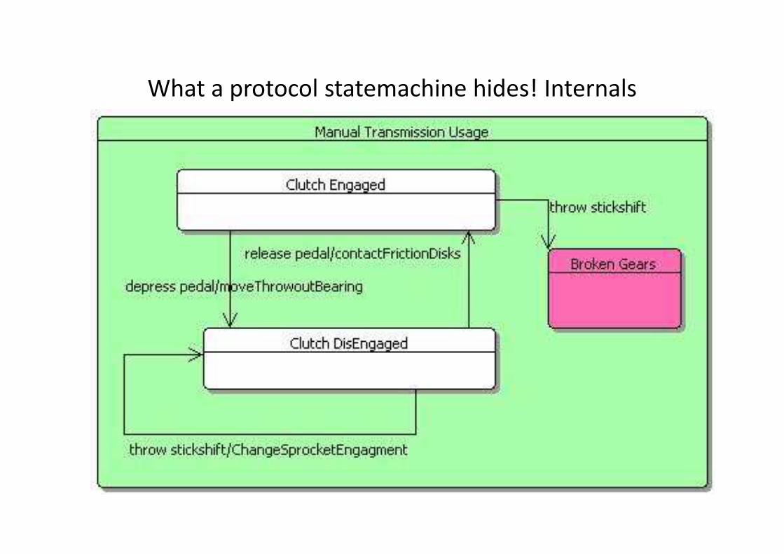
What a protocol statemachine hides! Internals

Context: Model-Based Verification
• Objectives– Close a gap in our ability to define relevant tests
• What system should not be expected to do– If test violates protocol, is the test is inappropriate?
• Ability to verify conformance of different implementations to same interface specifications
– Close gap in our SOA modeling approach – Close gap in our SOA modeling approach • wrt architectural interface modeling
• wrt the behavior of services
• Keep abreast of project modeling
– Approach to generating tests to cover requirements• Based on modeling capabilities new in UML 2
23 Oct 2008Assertion Library Tooling
18

Protocol statemachine
• Simpler than ordinary UML statemachines
• For characterizing the rules for invoking services at a software interface
– Protocol statemachines are linked in UML models to Interfaces, whereas “ordinary” UML statemachines are linked to components which realize interfaceslinked to components which realize interfaces
– Protocol statemachines are for defining the rules for using the services exposed at an interface, and so they conceal the actual workings of the component
• Transitions are triggered by invocations of service – the messages that arrive at the interface
• Shows changes in state externally visible (meaning, the modal behavior that matters to the client using the interface)
• No effects (internal call to private objects) allowed transitions

From UML 2 Spec
Protocol state machines are used to express usage protocols. Protocol state machines express the legal transitions that a classifier can trigger. The state machine notation is a convenient way to define a lifecycle for objects, or an order of the define a lifecycle for objects, or an order of the invocation of its operation.Protocol state machines do not preclude any specific behavioral implementation. They enforce legal usage scenarios. Interfaces and ports can be associated to this kind of state machines.

Component versus Interface
• Many actual components from diverse developers realize the SAME interface– Interfaces define external or “black box” view
– Interchangeability of components depends on concept of interface and ability to test components
• To test a component to see if it realizes a specified interface • To test a component to see if it realizes a specified interface depends on defining tests on the basis of protocol statemachine– Many actual behaviors may conform to the protocol
– “Ordinary” UML statemachine is called behavioral statemachine.
– Shows effects of transitions, the effects which are not allowed in a protocol statemachine

Conceptual Overview
Tests on
components Requirements
Concept of
Operations for SUTGenerative & Navigable Toolchain
Specifications
Architecture
Documents
components
conducted in
Testing
Environment
UML Eclipse
UML Models lead from interface design to tests

tra
ce
Traceability Summary
Requirements Level n+1
UML SRM Level jTest analysis
and reporting
tra
ce
Requirements Level n
30 Aug 2010Assertion Library Tooling
23
Refined UML Component and
Statemachine Model Level j+1
Suite of Event-based Test scripts
and reporting
Test analysis can
navigate back up
the traceability chain
to report context of
pass or fail
Test Outcomes
SUT running in
Test Environment
tra
cetr
ace
Why Model Component Interfaces?
• Modeling to the level of components is appropriate for verifying architecture
• Interfaces and the services they offer are the external view of components that matters
• Why?• Why?1. IV&V arch verification should not mess with internals
2. Model of component interfaces useful in verifying that components integrate as a working system
3. Service concept; is there a provider for every required interface? Match of providers and consumers provides a static audit of completeness.
Why Model Interface Protocols?
1. Designing the interface is more than specifying the services one-at-a-time– Preconditions for successful invocation of a service
are established by postcondition of a predecessor.
– Successful maintenance of an invariant condition not to be disrupted by an intervening invocation.
– Successful maintenance of an invariant condition not to be disrupted by an intervening invocation.
2. Protocol Statemachines add dynamic view of how the services make a complete set – Audit of service preconditions and postconditions
against the rules set out in the protocol establish a kind of dynamic completeness for the interface.

Why Model Interface …? Continued
3 Testing actual components is more than testing services one-at-a-time
– Does the component reject illegal messages, even when syntactically well-formed, based on dynamic context?
– Does the component respond to messages as specified by – Does the component respond to messages as specified by changes in what it will respond to?
4 Drill down to the actual behavior of implementations is mediated by protocols, which thus support traces from implementation back to requirements
– A behavioral statemachine and whitebox testing is one step of refinement beyond interface specification.

Back to mission incident

Deployment Of 2 Cameras from different vendors

Y-Camera Commercialization
• Y-Cameras specified as components providing an interface
– Y-Cameras can be provided by a number of qualified vendors
• Controlled by radiated commands originated at Mission Control, or by
autonomous on-board software
• Y-Camera systems offer a software interface for control
• Any component implementing the Y-Camera specs can, on demand, point at a
given environmental direction
Like a human cameraman told to point the camera in the direction of – Like a human cameraman told to point the camera in the direction of
the actor starring in a scene, Cameras should track an assigned target,
compensating for shifting platform attitude, until pointed elsewhere
or deactivated.
• Take-a-picture function requires start and end exposure services
– Can take a series of images while pointing at the same target
– May want to point in the right direction first, await some event
• Deactivate device to conserve power, aka sleep

Internal differences among cameras likely, best
kept private
Visibility indicators for Visibility indicators for
actual operations are not
appropriate for the
abstract services in an
interface

Four services exposed
• But they are not unrelated!
• How are they to be used?
• When you first establish communication with any Ycamera should you tell it to takePicture? Dynamic context, takePicture? Dynamic context, not static validation
• What state does it reach after 2 pointAt messages?– Note: not what will it DO
• Answers depend on the protocol statemachine

Commands illegal except as specified here

Tabular View
• Blue column labels show possible states
• Green row labels show possible events (messages)
• Black labels show next state, following the event represented in that column, if protocol permits!
• Some messages contrary to protocol in a given state
Quiescent StayingOnTarget TakingPicture
pointAt(target) StayingOnTarget StayingOnTarget Not Legal
startExposure() Not Legal TakingPicture Not Legal
endExposure() Not Legal Not Legal StayingOnTarget
sleep() Quiescent Quiescent Not Legal

Answers and discussion
What state is reached after 2 pointAt(target)
messages in a row?
1. Depends on context, by which we mean, the current
state, determined by the prior sequence of
messages. pointAt(target) should not be sent while
camera is taking a picture. If this should happen, camera is taking a picture. If this should happen,
results undefined and likely to be undesirable.
2. This protocol statemachine does not address the
question of whether the actual parameter (where to
point) changes in successive pointAt(target) events.
3. It is not the purpose of the protocol to model
intended semantics of the pointAt(target) message
Summary
Verification using UML interface and statemachine models
• Verification of software architectures by using UML(Unified Modeling Language) interface and statemachine models, in the context of the broader systems engineering problem of ensuring that complex systems can be integrated into a working whole.
• A failure this approach would have prevented: The case of the camera that did not take pictures because the command to take a picture needed to be preceded by a take pictures because the command to take a picture needed to be preceded by a command to enable the camera.
Verification in General
• The goal of verification is, in general terms, proving that certain properties hold or do not hold, of some subject system.
Software Architecture Verification in Particular
• More specifically, the property we are concerned with verifying is that the system can be produced by successful integration of a variety of separately produced subsystems, whose organization is described as an architecture. Hence, the topic of this presentation is software architecture verification.