modeling bidirectional contactless grid interfaces based ... · pdf file205 | p a g e modeling...
TRANSCRIPT
205 | P a g e
MODELING BIDIRECTIONAL CONTACTLESS GRID
INTERFACES BASED ON INDUCTIVE POWER
TRANSFER WITH A SOFT DC-LINK
Gaddameedi rakesh1, T. Venu gopal
2, V. Bhavani
3
ABSTRACT
Inductively coupled, bidirectional grid interfaces are gaining popularity as an attractive solution for vehicle-to-
grid (V2G) and grid-to-vehicle (G2V) systems. However, such systems conventionally use a large, electrolytic
dc-link capacitor as well as a large input inductor, leading to expensive, bulky, and less reliable systems.
Although, matrix converter (MC) based bidirectional inductive power transfer (BD-IPT) grid interfaces are
proposed as an alternative, implementation of safe and reliable MCs in BD-IPT applications is still a challenge,
due to the absence of natural freewheeling methods and higher complexity. As a solution, this paper proposes a
new, inductively coupled, bidirectional grid interface, while not a dc-link capacitor and an input inductor,
consisting of 2 back-to-back connected converters. In contrast to existing bidirectional grid converters, the
proposed system employs a simpler switching strategy with a lower switching frequency. A mathematical model,
that predicts the behavior of the introduced system, is additionally given. The feasibility of the proposed
technique and also the accuracy of the mathematical model are demonstrated through both simulations results
of a 1.1-kW prototype system.
Keywords—DC-link capacitor, electric vehicles (EVs), grid converters, inductive power transfer
(IPT), matrix converters (MCs).
I. INTRODUCTION
In recent years, the demand for electric vehicles (EVs) has risen significantly because of many reasons, like
improvement in EV technologies, high fuel costs associated with conventional vehicles, and increased
awareness on reducing greenhouse gas emissions. Moreover, with the emergence of vehicle-to-grid (V2G) and
grid-to-vehicle (G2V) technologies, EVs are proposed as energy storage devices for storage and retrieval of
energy for dynamic demand management [1]–[3].
Currently, hard-wired bidirectional grid interfaces are used for grid integration of EVs. Although hard-wired
interfaces between EVs and also the utility grid are simple, they must be suitably isolated to avoid the risk of
shock hazards [4]. However, they still increase the risk of electrocution, significantly under wet environments
and harsh weather conditions, like snow and ice, making safe use of hard-wired interfaces practically difficult.
Since these particular grid interfaces are equipped with long cables, they'll also be inconvenient and inflexible
[5]. In recent years, inductive power transfer (IPT) has emerged as a favored technique for supplying contactless
206 | P a g e
power for a wide range of applications [6]–[12]. In contrast to hardwired interfaces, contactless grid interfaces
based on bidirectional inductive power transfer (BD-IPT) technology have shown substantial promise as an
attractive solution for V2G and G2V applications because of their higher galvanic isolation, flexibility, and
efficiencies comparable to hard-wired systems [9]. However, the operating frequencies of BD-IPT systems are
usually much higher than the utility grid frequency. Therefore, contactless grid integration of EVs for V2G or
G2V applications involves a single or multistage frequency conversion, using one or more bidirectional power
electronic converters. Furthermore, as a typical BD-IPT system includes a sixth or eighth order, high-frequency
resonant network [13], control of such systems is more demanding in contrast to traditional applications.
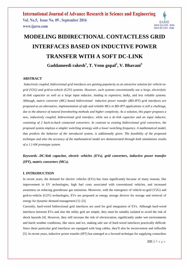
However, 2 differing kinds of bidirectional device topologies that are used for grid integration of BD-IPT
systems are presented in the literature [14], [15].
Fig.1. Converter topologies for grid integration of BD-IPT systems (a) grid inverter-based system (b) MC-
based system.
Out of the 2 topologies reported, one that is reported in [14] consists of a two-stage energy conversion method,
using 2 converters on the primary side of the BD-IPT system, as shown in Fig. 1(a). The converter on the front
end, that is referred to because the grid inverter, is driven by high-frequency PWM signals based on
proportional-resonant or direct-quadrature controllers. By doing thus, it converts the utility grid ac voltage to a
dc voltage and maintains the converted dc voltage at a relatively constant value.
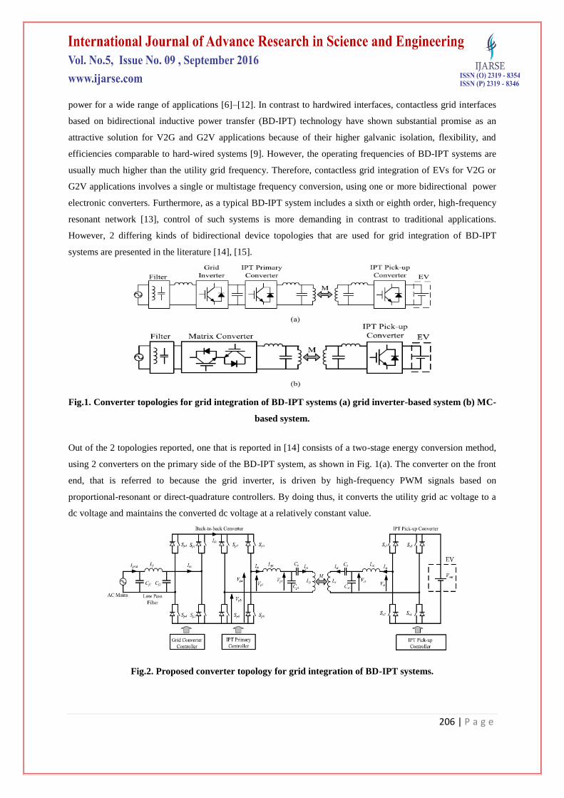
Fig.2. Proposed converter topology for grid integration of BD-IPT systems.
207 | P a g e
The device on the back end, called the IPT primary converter, and then converts the constant dc voltage at the
intermediate dc-link to an ac voltage at the resonant frequency, in order to drive the resonant network. Hence,
this system necessitates a large electrolytic dc-link capacitor and an input inductor for minimizing voltage ripple
at the intermediate dc-link and reducing input current ripples, respectively. Inclusion of these 2 energy storage
elements makes the system bulky and more expensive. in addition, numerous external factors like, kind of
dielectric material used, operating and storage temperatures, contribute to determining the life time of the dc-
link capacitor. As a result, inclusion of the dc-link capacitor compromises the reliability of the entire
system.Alternately, matrix converter (MC)-based bidirectional inductively coupled grid interfaces are proposed
in [15]. Being a direct ac–ac converter, the MC is able to convert low frequency ac voltage on the grid side to a
high-frequency ac voltage at the converter output. Consequently, this eliminates the necessity of a large input
inductor, dc-link capacitor, and also the additional ac–dc conversion stage in the grid inverter based system as
shown in Fig. 1(b). Hence, the MC-based system becomes less expensive and more compact in comparison to a
conventional grid inverter-based system. However, current commutation of the MC should be controlled using
precise and complicated multistep commutation algorithms. Thus, the complexity of the controller of the MC-
based system becomes significantly higher, particularly in BD-IPT applications wherever high frequency, high-
order resonant networks are present. Hence, reliable and safe operation of the MC is very demanding.
This paper presents an inductively coupled, bidirectional grid interface scheme that overcomes aforementioned
drawbacks of existing systems. The proposed system performs 2-stage energy conversion using two converters,
without having a constant or stiff dc-link voltage. Therefore, it eliminates the requirement of a large dc-link
capacitor. Due to the absence of the dc-link capacitor, a voltage with a large ripple, which is close to the peak of
the grid voltage, is manifested in the dc-link voltage of the given system. Hence, the dc-link of the proposed
system is referred to as soft dc-link during this paper. The large input inductor has also been excluded by
exploiting the inherent current source nature [9] of the parallel resonant circuit. This attributes to a more
compact, reliable, and a less expensive system in comparison to conventional grid inverter-based systems.
Moreover, in contrast to the present systems, the front end converter is operated employing a simple switching
strategy at utility grid frequency, with near-zero-voltage switching. The paper presents comprehensive
mathematical analyses and compares theoretical results with those obtained from a 1.1-kW MATLAB
simulation model to demonstrate system’s capability to realize regulated bidirectional power flow to/from the
grid. Furthermore, the total harmonic distortion (THD) of the grid current, power factor, and also the efficiency
of the overall system are given to investigate the performance of the proposed scheme. Results suggest that the
proposed bidirectional inductively coupled grid interface is efficient, reliable, and easy to implement, and
suitable for contactless V2G and G2V applications.
II. PROPOSED GRID-INTEGRATED BIDIRECTIONAL IPT SYSTEM
A schematic of the proposed grid integrated BD-IPT system is shown in Fig. 2. the primary side of the system
consists of 2 converters that are connected during a back-to-back configuration. The front end converter, which
is referred to as the grid converter, is directly interfaced with the utility grid. due to current source nature of the
208 | P a g e
tuned inductor–capacitor–capacitor– inductor (LCCL) resonant network [13], an input inductor isn't needed for
controlling the grid current. Therefore, the large input inductor is eliminated. Regardless of the direction of the
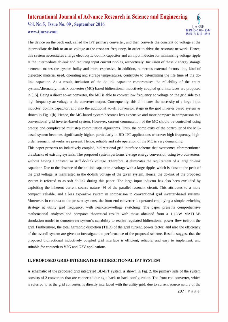
power flow, switching devices Sp1 and Sp4 remain ON throughout the complete positive half of the grid
voltage, whereas, during the negative half cycle of the grid voltage Sp2 and Sp3 remain ON. However, this
needs precise detection of zero-voltage crossings of the utility grid voltage, however measuring voltages
accurately near zero is practically a difficult task. To make the situation worse, incorrect detection of zero-
voltage crossings can lead to a phase-to-neutral short circuit through the grid converter. When the grid voltage,
Vgrid>_V + and Vgrid<_V −, the grid converter is said to be in normal operation. Due to the switching of Sp1 − Sp4
as shown in Fig. 3, a dc voltage with a ripple of Vin is formed in the dc-link, where Vin is the peak of the utility
grid voltage. Thus, the grid converter functions as a rectifier at utility grid frequency when the power flows from
the grid to the EV, while it operates as an inverter when the power flow is in reverse direction, i.e., from the EV
to the grid.
Fig. 3. Operation of Sp 1 − Sp 4 with deadband.
Fig. 4. Voltages produced by IPT primary and pick-up converters.
The IPT primary converter in Fig. 2 is employed for converting the dc voltage across the soft dc-link into an ac
voltage at resonant frequency. Switching devices Sp5 and Sp6 of the IPT primary converter are switched at the
resonant frequency fT , with a duty cycle of 50%, to generate a square wave voltage Vpa as shown in Fig. 4. In
order to generate Vpb , Sp7 , and Sp8 are operated at fT with a 50% duty cycle but with a phase delay ϕ1 with
respect to Vpa , which is referred to as the primary phase modulation. Due to the difference between Vpa and Vpb,
209 | P a g e
an ac voltage Vpi at fT manifests at the output of the primary IPT converter, and the effective value of Vpi depends
on the primary phase modulation. Subsequently, Vpi produces a current Ipt in the primary winding Lp which is
loosely coupled to the pick-up winding Ls. The IPT pick-up converter in Fig. 2 is also operated using the same
principle, but with a relative phase shift θ with respect to Vpi , as illustrated in Fig. 4. This converts the dc
voltage Vout , which represents an EV for simplicity, to an ac voltage Vsi at the same resonant frequency fT . As a
result, a current Ist in the pick-up winding Ls is generated. Contactless power transfer takes place across the air
gap between the primary and the pick-up windings due to the mutual coupling between them, and the relative
phase angle between Ipt and Ist , which essentially depends on θ, determines the magnitude and direction of
power flow. In order to maintain the power factor of the system near unity, the relative phase angle θ is
maintained at •} 90◦ [9], and hence, the regulation of power is accomplished by controlling the pick-up phase
modulation ϕ2.
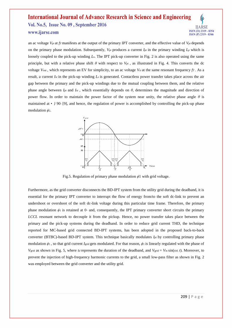
Fig.5. Regulation of primary phase modulation ϕ1 with grid voltage.
Furthermore, as the grid converter disconnects the BD-IPT system from the utility grid during the deadband, it is
essential for the primary IPT converter to interrupt the flow of energy from/to the soft dc-link to prevent an
undershoot or overshoot of the soft dc-link voltage during this particular time frame. Therefore, the primary
phase modulation ϕ1 is retained at 0◦ and, consequently, the IPT primary converter short circuits the primary
LCCL resonant network to decouple it from the pickup. Hence, no power transfer takes place between the
primary and the pick-up systems during the deadband. In order to reduce grid current THD, the technique
reported for MC-based grid connected BD-IPT systems, has been adopted in the proposed back-to-back
converter (BTBC)-based BD-IPT system. This technique basically modulates Ipi by controlling primary phase
modulation ϕ1 , so that grid current Igrid gets modulated. For that reason, ϕ1 is linearly regulated with the phase of
Vgrid as shown in Fig. 5, where td represents the duration of the deadband, and Vgrid = Vin sin(ωL t). Moreover, to
prevent the injection of high-frequency harmonic currents to the grid, a small low-pass filter as shown in Fig. 2
was employed between the grid converter and the utility grid.

210 | P a g e
III. MATHEMATICAL MODEL
Due to the operation of the grid converter, a dc voltage of Vin |sin (ωL t)| is produced across the soft dc-link,
where ωL represents the frequency of the utility grid voltage. Hence, the IPT primary converter produces an ac
voltage at its output, which can be given by
Fig. 6. Reduced LCL network.
where ωT is the angular resonant frequency.
Furthermore, an expression for the variation of ϕ1 can be developed using Fourier series as
The output voltage of the pick-up converter can also be derived as
In order to simplify the LCCL network shown in Fig. 2, the equivalent impedance Zpt of Lp and Cp at an angular
frequency ω can be defined as Zpt = Lpω − 1/ωCp . Zpt is inductive for the frequencies considered in this paper
and hence, Lptω = Zpt = Lpω − 1/ωCp where Lpt represents the equivalent inductance of Lp and Cp . Therefore, Lpt
can be written as
Similarly on the pick-up side, Ls and Cs can be reduced by defining another equivalent inductor Lst , which is
given by
Therefore, the LCCL network can be reduced to an inductor– capacitor–inductor (LCL) network, as depicted in
Fig. 6. The mutual coupling M between Lp and Ls can be expressed as M = k_LpLs , where k is the coefficient of
coupling. Therefore, the induced voltages Vpr and Vsr of the primary and the pick-up networks can be derived as
follows:
211 | P a g e
The currents Ipi , Isi , Ipt , and Ist for an LCL network are derived in [13] as given below
Thus, Idc can be written as a product of Ipi and a function fprimary (t) that represents the operation of the IPT
primary converter. According to Fig. 4, fprimary (t) is a function that follows the exact shape of Vpi , however, with
a unity magnitude.
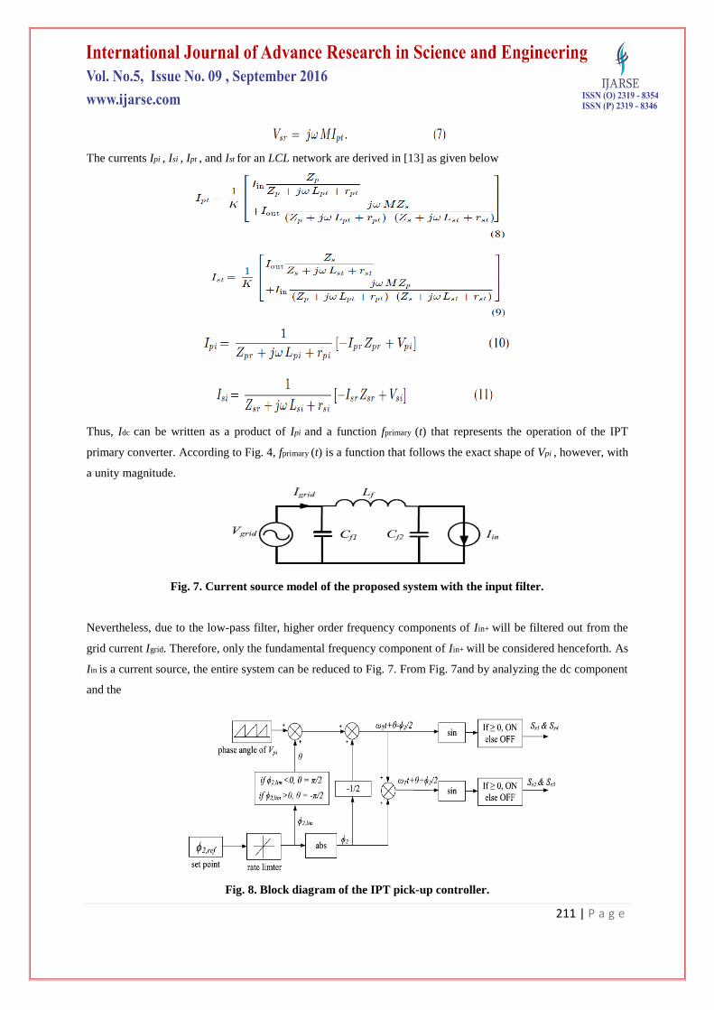
Fig. 7. Current source model of the proposed system with the input filter.
Nevertheless, due to the low-pass filter, higher order frequency components of Iin+ will be filtered out from the
grid current Igrid. Therefore, only the fundamental frequency component of Iin+ will be considered henceforth. As
Iin is a current source, the entire system can be reduced to Fig. 7. From Fig. 7and by analyzing the dc component
and the
Fig. 8. Block diagram of the IPT pick-up controller.
212 | P a g e
IV. CONTROL SYSTEM
An open loop control system is introduced to the pick-up side to control the magnitude and direction of the
power flow of the proposed system. The block diagram of the pick-up controller is presented in Fig. 8. Based on
the amount of power required, the corresponding pick-up phase modulation ϕ2 can be calculated using for θ =
•}π/2, and set as the reference pick-up phase modulation ϕ2,ref for the pick-up controller. For power flow from
the primary to the pick-up, ϕ2,ref should be positive, while for power flow from the pick-up to the primary, ϕ2,ref
should be set as a negative value. Therefore, ϕ2,ref varies between 0 and π radians for power flow from the
primary to the pickup with θ = −π/2, whereas it is confined between 0 and –π radians when the power flow is
from the pick-up to the primary. To ensure a smooth transfer of the set point from one value to another, ϕ2,ref is
passed through a rate limiter with a predefined value. The absolute value of the rate limited ϕ2,ref occurs to be the
pick-up phase modulation for the IPT pick-up converter, as seen from Fig. 8. Furthermore, the phase angle of
the primary converter output voltage Vpi is employed as an input to the pickup controller to accurately maintain
the required phase shift θ of the pick-up output voltage. The resulting pick-up phase modulation ϕ2 is then
divided into −ϕ2/2 and ϕ2/2 on the time axis, and each pair of switches are operated as expounded in Fig. 8.
TABLE I
PARAMETERS OF THE PROTOTYPE BD-IPT SYSTEM
V. SIMULATION RESULTS
Discrete,Ts = 5e-005 s.
powergui
controller
v+-
v+-v
+-
v+-
v+-
v+-
v+-
v+-
v+-
v+-
v+-
Results
1 2
g CE
g CE
g CE
g CE
g CE
g CE
g CE
g CE
g CE
g CE
g CE
g CE
Vpt
Vout
Vpi
I_grid
I_in
I_si
I_stI_pt
Vdc
Sp1
Sp2
Vg2
Vg1
V_grid
Vpa
Vpb
Vsi
Vst
I_dc
I_pi
[S2_S3]
[S1_S4]
i+
-i
+-
i+
-
i+
-
i+
-
i+
-
i+
-
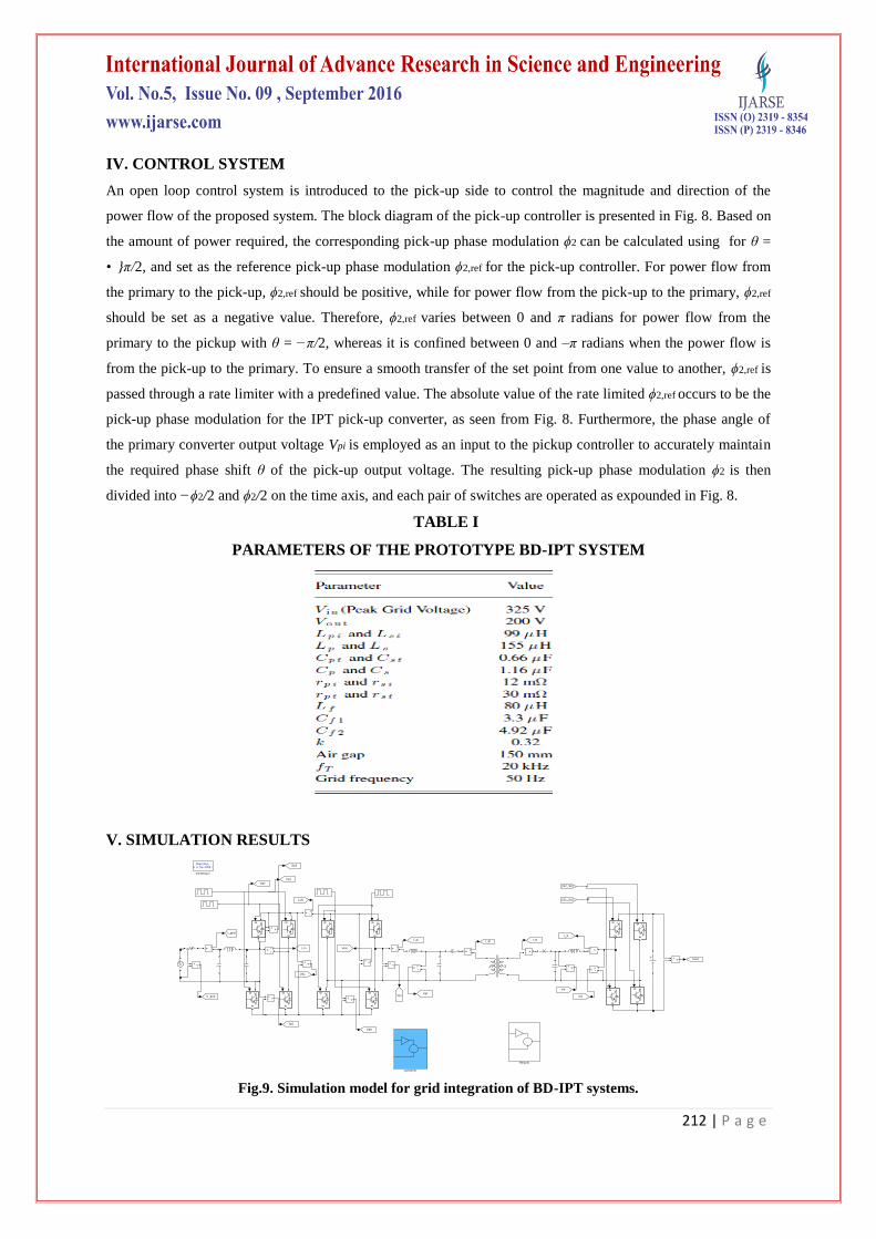
Fig.9. Simulation model for grid integration of BD-IPT systems.
213 | P a g e
0 0.1 0.2 0.3 0.4 0.5 0.6 0.7 0.8 0.9 1-500
0
500
Vgrid
0 0.1 0.2 0.3 0.4 0.5 0.6 0.7 0.8 0.9 10
0.5
1
Vg1&
Vg2
0 0.1 0.2 0.3 0.4 0.5 0.6 0.7 0.8 0.9 1-500
0
500
Sp1&
Sp2
0 0.1 0.2 0.3 0.4 0.5 0.6 0.7 0.8 0.9 10
200
400
Time
Vdc
0 0.1 0.2 0.3 0.4 0.5 0.6 0.7 0.8 0.9 10
200
400
Vpa
0 0.1 0.2 0.3 0.4 0.5 0.6 0.7 0.8 0.9 10
200
400
Vpb
0 0.1 0.2 0.3 0.4 0.5 0.6 0.7 0.8 0.9 1-500
0
500
Vpi
0 0.1 0.2 0.3 0.4 0.5 0.6 0.7 0.8 0.9 1-500
0
500
Time
Vsi
0 0.1 0.2 0.3 0.4 0.5 0.6 0.7 0.8 0.9 1-500
0
500
Ipi
0 0.1 0.2 0.3 0.4 0.5 0.6 0.7 0.8 0.9 1-500
0
500
Isi
0 0.1 0.2 0.3 0.4 0.5 0.6 0.7 0.8 0.9 1-200
0
200
Time
Igrid
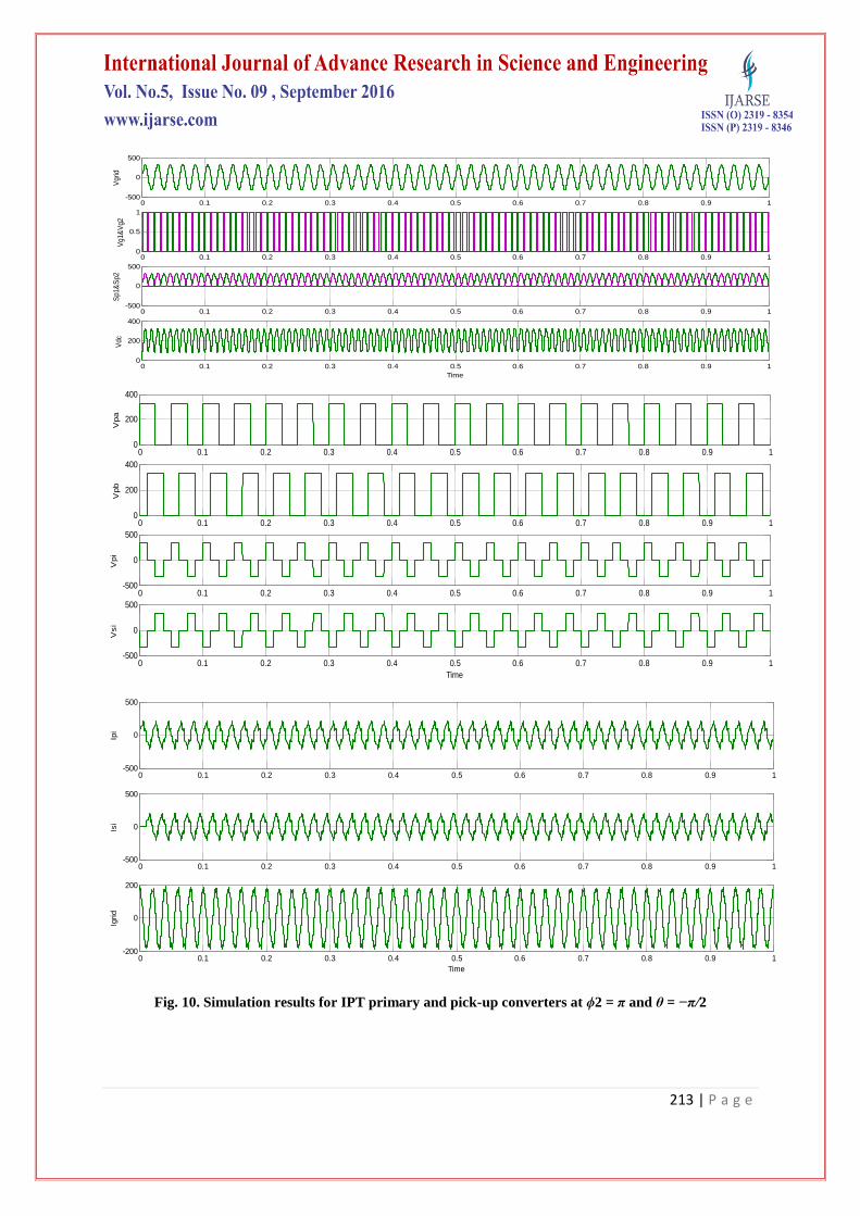
Fig. 10. Simulation results for IPT primary and pick-up converters at ϕ2 = π and θ = −π/2

214 | P a g e
0 0.1 0.2 0.3 0.4 0.5 0.6 0.7 0.8 0.9 1-500
0
500
Vgrid
0 0.1 0.2 0.3 0.4 0.5 0.6 0.7 0.8 0.9 10
0.5
1
Vg1&
Vg2
0 0.1 0.2 0.3 0.4 0.5 0.6 0.7 0.8 0.9 1-500
0
500
Sp1&
Sp2
0 0.1 0.2 0.3 0.4 0.5 0.6 0.7 0.8 0.9 10
200
400
Time
Vdc
0 0.1 0.2 0.3 0.4 0.5 0.6 0.7 0.8 0.9 10
200
400
Vpa
0 0.1 0.2 0.3 0.4 0.5 0.6 0.7 0.8 0.9 10
200
400
Vpb
0 0.1 0.2 0.3 0.4 0.5 0.6 0.7 0.8 0.9 1-500
0
500
Vpi
0 0.1 0.2 0.3 0.4 0.5 0.6 0.7 0.8 0.9 1-500
0
500
Time
Vsi
0 0.1 0.2 0.3 0.4 0.5 0.6 0.7 0.8 0.9 1-500
0
500
Ipi
0 0.1 0.2 0.3 0.4 0.5 0.6 0.7 0.8 0.9 1-500
0
500
Isi
0 0.1 0.2 0.3 0.4 0.5 0.6 0.7 0.8 0.9 1-200
0
200
Time
Igrid
Fig.11 Simulation results for grid side at ϕ2 = π and θ = −π/2
215 | P a g e
0 0.1 0.2 0.3 0.4 0.5 0.6 0.7 0.8 0.9 1-500
0
500
Vgrid
0 0.1 0.2 0.3 0.4 0.5 0.6 0.7 0.8 0.9 10
0.5
1
Vg1&
Vg2
0 0.1 0.2 0.3 0.4 0.5 0.6 0.7 0.8 0.9 1-500
0
500
Sp1&
Sp2
0 0.1 0.2 0.3 0.4 0.5 0.6 0.7 0.8 0.9 10
200
400
Time
Vdc
0 0.1 0.2 0.3 0.4 0.5 0.6 0.7 0.8 0.9 10
200
400
Vpa
0 0.1 0.2 0.3 0.4 0.5 0.6 0.7 0.8 0.9 10
200
400
Vpb
0 0.1 0.2 0.3 0.4 0.5 0.6 0.7 0.8 0.9 1-500
0
500
Vpi
0 0.1 0.2 0.3 0.4 0.5 0.6 0.7 0.8 0.9 1-500
0
500
Time
Vsi
0 0.1 0.2 0.3 0.4 0.5 0.6 0.7 0.8 0.9 1-500
0
500
Ipi
0 0.1 0.2 0.3 0.4 0.5 0.6 0.7 0.8 0.9 1-500
0
500
Isi
0 0.1 0.2 0.3 0.4 0.5 0.6 0.7 0.8 0.9 1-200
0
200
Time
Igrid
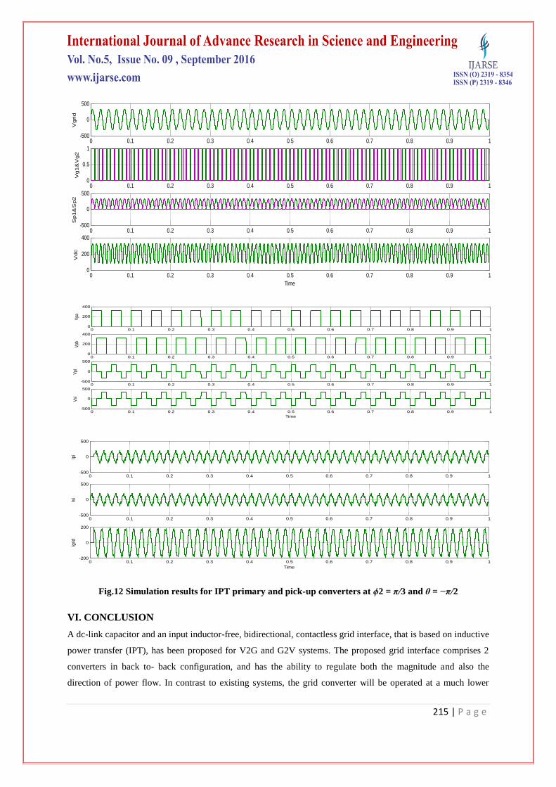
Fig.12 Simulation results for IPT primary and pick-up converters at ϕ2 = π/3 and θ = −π/2
VI. CONCLUSION
A dc-link capacitor and an input inductor-free, bidirectional, contactless grid interface, that is based on inductive
power transfer (IPT), has been proposed for V2G and G2V systems. The proposed grid interface comprises 2
converters in back to- back configuration, and has the ability to regulate both the magnitude and also the
direction of power flow. In contrast to existing systems, the grid converter will be operated at a much lower
216 | P a g e
switching frequency employing a simpler switching strategy. A mathematical model that may estimate grid
currents, converter voltages, and currents has been given. In order to investigate the feasibility of the proposed
scheme, as well as the accuracy of the mathematical model, a MATLAB simulation model. Good agreement
between theoretical, simulation results validates the accuracy of the proposed mathematical model. Moreover,
the THD of the grid current, the power factor, and also the efficiency of the simulation prototype have been
investigated for both directions of power flow, and also the results suggest that the system exhibits a steady
efficiency profile with reasonably low THD and a unity power factor, throughout the considered operational
range.
REFERENCES
[1] J. Sexauer, K. McBee, and K. Bloch, “Applications of probability model to analyze the effects of electric
vehicle chargers on distribution transformers,” IEEE Trans. Power Syst., vol. 28, no. 2, pp. 847–854, Oct.
2013.
[2] M. Etezadi-Amoli, K. Choma, and J. Stefani, “Rapid-charge electricvehicle stations,” IEEE Trans. Power
Del., vol. 25, no. 3, pp. 1883–1887, Jul. 2010.
[3] Z. Wang and S. Wang, “Grid power peak shaving and valley filling using vehicle-to-grid systems,” IEEE
Trans. Power Del., vol. 28, no. 3, pp. 1822–1829, Jul. 2013.
[4] M. Yilmaz and P. Krein, “Review of the impact of vehicle-to-grid technologies on distribution systems
and utility interfaces,” IEEE Trans. Power Electron., vol. 28, no. 12, pp. 5673–5689, Dec. 2013.
[5] H. Wu, A. Gilchrist, K. Sealy, and D. Bronson, “A high efficiency 5 kW inductive charger for EVs using
dual side control,” IEEE Trans. Ind. Informat., vol. 8, no. 3, pp. 585–595, Aug. 2012.
[6] A. W. Green and J. T. Boys, “10 kHz inductively coupled power transferconcept and control,” in Proc.
Fifth Int. Conf. Power Electron. Variable- Speed Drives, Oct. 1994, pp. 694–699.
[7] S. R. Hui and W. Ho, “A new generation of universal contactless battery charging platform for portable
consumer electronic equipment,” IEEE Trans. Power Electron., vol. 20, no. 3, pp. 620–627, Jun. 2005.
[8] P. Si, A. P. Hu, S.Malpas, and D. Budgett, “A frequency controlmethod for regulating wireless power to
implantable devices,” IEEE Trans. Biomed. Circuits Syst., vol. 2, no. 1, pp. 22–29, Mar. 2008.
[9] U. K. Madawala and D. J. Thrimawithana, “A bidirectional inductive power interface for electric vehicles
in V2G systems,” IEEE Trans. Ind. Electron., vol. 58, no. 10, pp. 4789–4796, Oct. 2011.
[10] J. Huh, S. Lee, C. Park, G.-H. Cho, and C.-T. Rim, “High performance inductive power transfer system
with narrow rail width for on-line electric vehicles,” in Proc. IEEE Energy Convers. Congr. Expo., Sep.
2010, pp. 647–651.
[11] J. M. Miller, O. Onar, C. White, S. Campbell, C. Coomer, L. Seiber, R. Sepe, and A. Steyerl,
“Demonstrating dynamic wireless charging of an electric vehicle: The benefit of electrochemical
capacitor smoothing,” IEEE Power Electron. Mag., vol. 1, no. 1, pp. 12–24, Mar. 2014.

217 | P a g e
[12] T. Imura and Y. Hori, “Maximizing air gap and efficiency of magnetic resonant coupling for wireless
power transfer using equivalent circuit and Neumann formula,” IEEE Trans. Ind. Electron., vol. 58, no.
10, pp. 4746–4752, Oct. 2011.
[13] D. J. Thrimawithana and U. K. Madawala, “A generalized steady-state model for bidirectional IPT
systems,” IEEE Trans. Power Electron., vol. 28, no. 10, pp. 4681–4689, Oct. 2013.
[14] R. Miskiewicz, A. Moradewicz, and M. Kazmierkowski, “Contactless battery charger with bi-directional
energy transfer for plug-in vehicles with vehicle-to-grid capability,” in Proc. IEEE Int. Symp. Ind.
Electron., 2011, pp. 1969–1973.
[15] D. J. Thrimawithana and U. K. Madawala, “A novel matrix converter based bi-directional IPT power
interface for V2G applications,” in Proc. Energy Conf. Exhib., Dec. 2010, pp. 495–500.