modeling and simulation of multi-pulse cycloconvereter-fed ... · thyristor to control its firing...
TRANSCRIPT
Modeling and Simulation of multi-pulse Cycloconvereter-fed ACinduction motor and study of output power factor
Rezgar Mohammed Khalil Maamoon Al-Kababjie
B.Sc. & M.Sc. Ph.D.
Electrical Engineering
[email protected][email protected]
AbstractThe need for use of cycloconverters is in controlling a.c motors at
low speed drive especially in high power application. The MATLAB-SIMULINK model for three pulse, six pulse and twelve pulse three phaseto three phase cycloconverter has been constructed. The control strategyof supplying the firing pulses is based on the cosine wave crossingmethod. The SIMULINK model for the control circuits to perform theprocedure of this strategy has been constructed. A control circuit for eachthyristor to control its firing pulses has been constructed separately toprevent any complexity in the control circuit. An R-L load was used. Inadditional a three phase induction motor has been connected to test thereliability of the system in controling the output frequency and then themotor speed. The present study includes circulating current and semi-circulating current modes of operation with study of measuring andcorrection of output power factor of the cycloconverter and outputvoltage waveform harmonics.
Keywords:Three-phase to Three-phase, Cycloconvereter, Modeling andSimulation, MATLAB-SIMULINK model
نمذجة وتمثیل مغیر تردد دوري متعدد النبضات یغذي محركا حثیا متناوبا ودراسة عامل قدرة االخراج
ریزكار محمد خلیلمأمون فاضل الكبابجي . د
ماجستیر ھندسة قسم الھندسة الكھربائیة كھربائیة

الملخصإن الحاجة إلى استخدام مغیر التردد الدوري ھي في السیطرة على المحركات المتناوبة
تم في ھذا البحث تمثیل . في التطبیقات التي تحتاج إلى سرعة واطئة وخاصة عند القدرة العالیةالثي النبظة، سداسي النبضة، وذو ث) ثالثة أطوار إلى ثالثة أطوار(منظومة مغیر التردد الدوري
MATLAB(االثنتي عشرة نبضة باستخدام تقنیة - SIMULINK .( وارتكزت خطة التحكمفي نبضات القدح في للثایرسترات على طریقة تقاطع الموجة الجیب تمامیة، وتم تمثیل دوائر
ثایرستر أدى إلى إن تمثیل دائرة سیطرة خاصة بقدح كل. السیطرة الالزمة للقیام بھذه المھمةتم استخدام حمل حثي باالضافة إلى أختبار منظومة السیطرة بربط . عدم التعقید فیھا وسھولتھا
محرك متناوب ثالثي الطور إلى المنظومة ، وتم تغییر سرعتھ بتغییر تردد االخراج للمغیر وھو التیار شبھ الدائر مع وشمل ھذا العمل حاالت التشغیل ذات التیار الدائر وذات. في حالة اشتغال
. دراسة لعامل قدرة االخراج للمغیر مع فولتیة اخراج غیر جیبیة فضال عن تشوه تیار االخراجباالضافة إلى تحلیل موجات فولتیة االخراج . كما وجدت قیمة متسعة تحسین عامل قدرة االخراج
. للمغیر في طیف الترددات
1-Introduction:
Frequency changers is an expanding field of power conversiontechnology. The increasing utilization of a.c motors in variable speeddrives and the generation of electrical power from variable speed sourcesare examples of this field applications. Early systems of frequencychangers incorporated rotating machines. These systems have beenlargely supplanted by static frequency changers using powersemiconductor devices.
Static frequency changers can be broadly classified into two types:the First employ an intermediate d-c lin k which consist ofrectification of a-c power to d-c and then inversion the d-c power to a-c atvariable frequency. The second type performs the power convertingfunction in a single stage without any intermediate d-c link. That is meanthe a-c supply frequency is converted directly to another frequency. Thecycloconverter is a member of the second class[1].
Cycloconverters are suitable for large a-c machines because it hasadvantages: it has high efficiency owing to the simple construction of themain circuit, which consists, in its basic form, simply of an array of
Received 19 Oct. 2005 Accepted 7 May 2006
thyristor switches [5], and it is also naturally commutative, and no forcedcommutation circuits are necessary. As the same time it suffers fromsome disadvantages. It has a low maximum output frequency comparedto the input frequency, and it suffers from voltage distortion. Theapplication of a cycloconverter is rather limited, because the controlcircuit is often very complex, and therefore expensive[2].
One of the modern simulation software packages is SIMULINK,which is an extension of the popular MATLAB software. MATLABSIMULINK is specially designed for simulating dynamic systems. Itsolves numerical problems in a fraction of time compared to othersoftware packages, and it is more interactive than others.
In this work the MATLAB-SIMULINK packages have been usedfor modeling and simulating the cycloconverter system and its controlcircuits.
2-The cycloconverter power circuit:
The basic building block of a cycloconverter is the phasecontrolled converters. Anti-parallel combination of two such blocksforms one phase at the output. It is simply a dual converter as shown infig.(2-1), which is controlled, through a time varying phase modulation ofits firing pulses, so that it produces an alternating, rather than a direct,output voltage.
By appropriate control, it is possible to produce a continuousvariation of both the amplitude and frequency of the output voltage wave.
The method of connecting the phase controlled convertersgoverns their operation in three modes. These are the non-circulating, thecirculating, and the semi-circulating current modes. Mainly, the outputwaveform is a function of the converters control algorithm. In practicalapplication, the three-phase to three-phase cycloconverter is commonlyrequired to derive a three-phase output from a three-phase input. Themost logical method for producing a three-phase output, is to use threesymmetrical independent, dual converters, one for each output phase.Fig(2-2) represents a three-phase to three-phase three-pulsecycloconverter.

In order to control the output voltage of the phase-controlledconverter or cycloconverter, it is necessary to control the phase of thethyristor firing pulses. Many alternatives exist for achieving this end. Thetask of a firing controller is to generate time-varying sequences of pulsesfor triggering the thyristor devices. In this work the control strategy isbased on taking the natural sampling in corporating the cosine wavecrossing control technique, which has been adequately explained with thecycloconverter operation in the well-known text book [1].
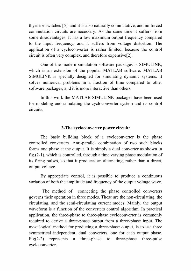
As in case of the rectifier or phase-controlled converter circuit,from the view point of reducing the external harmonic voltages andcurrents to a minimum, the pulse number of the cycloconverter circuitshould be as high as possible. Fig(2-3) and (2-4) represents the diagramof three-phase to three-phase six-pulse and twelve pulse bridgecycloconverters respectevely. [1]
Fig (2-1): 3-pulse 3-phase to 1- phase dual converter
circulatingcurrentreactor
Load

Fig (2-2): 3-pulse 3-phase to 3-phase cycloconverter
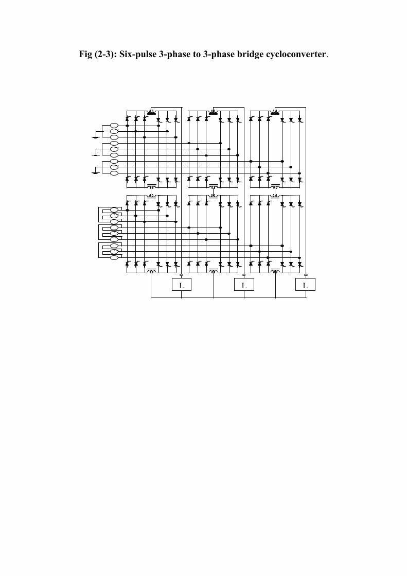
Fig (2-3): Six-pulse 3-phase to 3-phase bridge cycloconverter.
L1Output\
~
L2
L3
~~
~~~
~
~~
~
~~
~
~~
~
~~
~
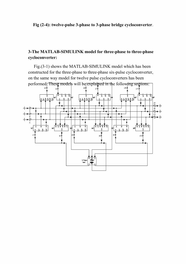
Fig (2-4): twelve-pulse 3-phase to 3-phase bridge cycloconverter.
3-The MATLAB-SIMULINK model for three-phase to three-phasecycloconverter:
Fig.(3-1) shows the MATLAB-SIMULINK model which has beenconstructed for the three-phase to three-phase six-pulse cycloconverter,on the same way model for twelve pulse cycloconverters has beenperformed. These models will be explained in the following sections:
Fig (3-1): The MATLAB-SIMULINK model for 6-pulse 3-phase to3-phase cycloconverter
(3-1) Three-phase input supply:
A number of pure sinusoidal single phase supply are formed torepresent a double secondary output of three-phase transformer. Wherefirst set represents the first secondary winding which shifted 30 degree toperform the zero crossing instant when using delta-star connection ofthree-phase transformer, and the second set represents the secondwindings, and it gives an inherently 180 degree phase shift between theinput voltage waves for each converter. This makes the instants ofstarting a new timing waves, i.e. the instants of zero firing angle for thepositive converter coincide with those of the negative converter. Whichsimplifies the control circuit model. In the case of 12-pulsecycloconverter, the input terminals of each of the 6 individual 6-pulseconverters are fed from separate secondary windings on the inputtransformer. It should be noted that it is not permissible to use the samesecondary winding for more than one converter. This is because each 12-pulse converter, by itself, requires two completely isolated transformersecondary winding.
(3-2) Dual-Converters:
Six SIMULINK sub-systems represents six phase controlledconverters has been constructed and indicated as pg and ng. Fig.(3-2) a,and b shows the connection of thyristors in positive and negativeconverters respectively.

(a) (b)
Fig (3-2): MATLAB-SIMULINK model for positive and negativeconverters respectively
(3-3) The Control Circuit:
As mentioned before the control strategy based on cosine wavecrossing control method, so we will have three timing waves and threereference waves and a lot of intersection points, which means that thecontrol circuit and control program will be very complex. To make thistask more simple, and to obtain an online and variable control on thecycloconverter system, a SIMULINK model of control circuit forcontrolling the firing pulses of each thyristor has been constructed, i.e wehave (18) control circuits for 3-pulse cycloconverter one for eachthyristor and (36) circuits for 6-pulse cycloconverter and (72) circuits for12-pulse cycloconverter.
Each control circuit based on generating the timing wave for thecorresponding thyristor. On the other hand a separate sub-system forgenerating three-phase reference waves and distribute them on thyristorshas been performed. So in each control circuit we have one timing waveand one reference wave, with appropriate monitoring for intersections atthe wanted slope of the timing wave and passing adequate time andamplitude triggering pulse to the thyristor at the wanted intersections. Forsemi-circulating current mode of operation a closed loop control circuitwill be needed, were the pulses from the positive and negative firingpulse generators are transmitted to the positive and negative convetersthrough gates. The control signals for these gates are respectively the

output signals from the positive and negative current level detectors.Fig.(3-3) a and b illustrates SIMULINK sub-system models of a singlecontrol circuit for circulating current and semi-circulating current modesof operation respectively.
(a)
(b)Fig (3-3): MATLAB-SIMULINK models for single thyristor control
circuits a-circulating current cycloconverter. b-semi-circulatingcurrent cycloconverter.
4- Results Of Output waveforms:
The different operation modes of 3-pulse, 6-pulse and 12-pulsecycloconverter systems were carried out. An R-L load was used.
Fig. (4-1) shows output phase voltages and currents for differentmodes of operation of the 3-pulse cycloconverter.

V V
A A
(a) (b)
Fig.(4-1): Output phase voltages and currents for 3-pulse cycloconverterwith R-L load and fo=10Hz a- Circulating current mode. b- Semi-
circulating current modeFig. (4-1) shows output phase voltages and currents for different modesof operation of the 3-pulse cycloconverter.
Fig. (4-2) shows output phase voltages and currents for differentmodes of operation of the 6-pulse bridge cycloconverter.
This type of circuit is commonly used for 3-phase a-c machineloads, since it is usually a simple matter to electrically isolate the 3-phasewindings of the machine from one another.
Fig. (4-3) shows the output phase voltages and currents ofcirculating current 12-pulse bridge cycloconverter.
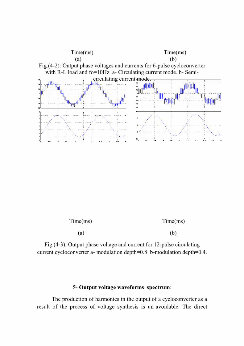
Time(ms) Time(ms)(a) (b)
Fig.(4-2): Output phase voltages and currents for 6-pulse cycloconverterwith R-L load and fo=10Hz a- Circulating current mode. b- Semi-
circulating current mode.
Time(ms) Time(ms)
(a) (b)
Fig.(4-3): Output phase voltage and current for 12-pulse circulatingcurrent cycloconverter a- modulation depth=0.8 b-modulation depth=0.4.
5- Output voltage waveforms spectrum:
The production of harmonics in the output of a cycloconverter as aresult of the process of voltage synthesis is un-avoidable. The direct

process of frequency changing makes the harmonics functions of both theinput and the output frequencies. Thus, the main class of distortion termsconstitute beat frequency components having frequencies which are bothsum and difference of multiples of both (fo) and (fin). There are severalfactors affecting the harmonic content of the waveforms. Non circulatingcurrent mode of operation produces more complex harmonics thancirculating mode of operation due to the zero current distortion. Inaddition to this, the pulse number effects the harmonic content. A greaternumber of pulses has less harmonic content. Therefore, a 6-pulsecycloconverter produces less harmonics than a 3-pulse cycloconverter.Moreover, if the output frequency gets closer to the input frequency, theharmonics increase. Finally, low power factor and discontinuousconduction, both contribute to harmonics[3].
The general observed frequency spectrum of the proposed systemwas found to be:
foh = │p (2 m – 1) * fin ± 2 n fo │…….(1)
foh = │p m fin ± (2 n + 1) * fo │ …….(2)
Where: foh is the harmonic component in the output voltage: m isany integer from 1 to infinity
n is any integer from 0 to infinity
In circulating current mode, the two converters are operatedsimultaneously during the hole output cycle. Thus, it is expected that theharmonics having (+) sign are the same as those with (-) sign in equation1 and 2, but this is not the same in the semi-circulating mode, as shown infig.(5-1).

(a) (b)
Fig.(5-1): The spectrum of the output voltage waveforms of fig.(4-1) aand b respectively
The spectrum for the case of 6-pulse cycloconverter is shown infig.(5-2). It is obvious that the fundamental component for 6-pulsescycloconverter is grater than with 3-pulse cycloconverter and less otherfrequency harmonics. And with equations 1 & 2 harmonics in 6-pulsecycloconverter will appear around beating frequencies double that with3-pulse cycloconverter.
(a) (b)
Fig.(5-2): The spectrum of the output voltage waveforms of fig.(4-2) aand b respectively
Inductionmotor
1 Kw
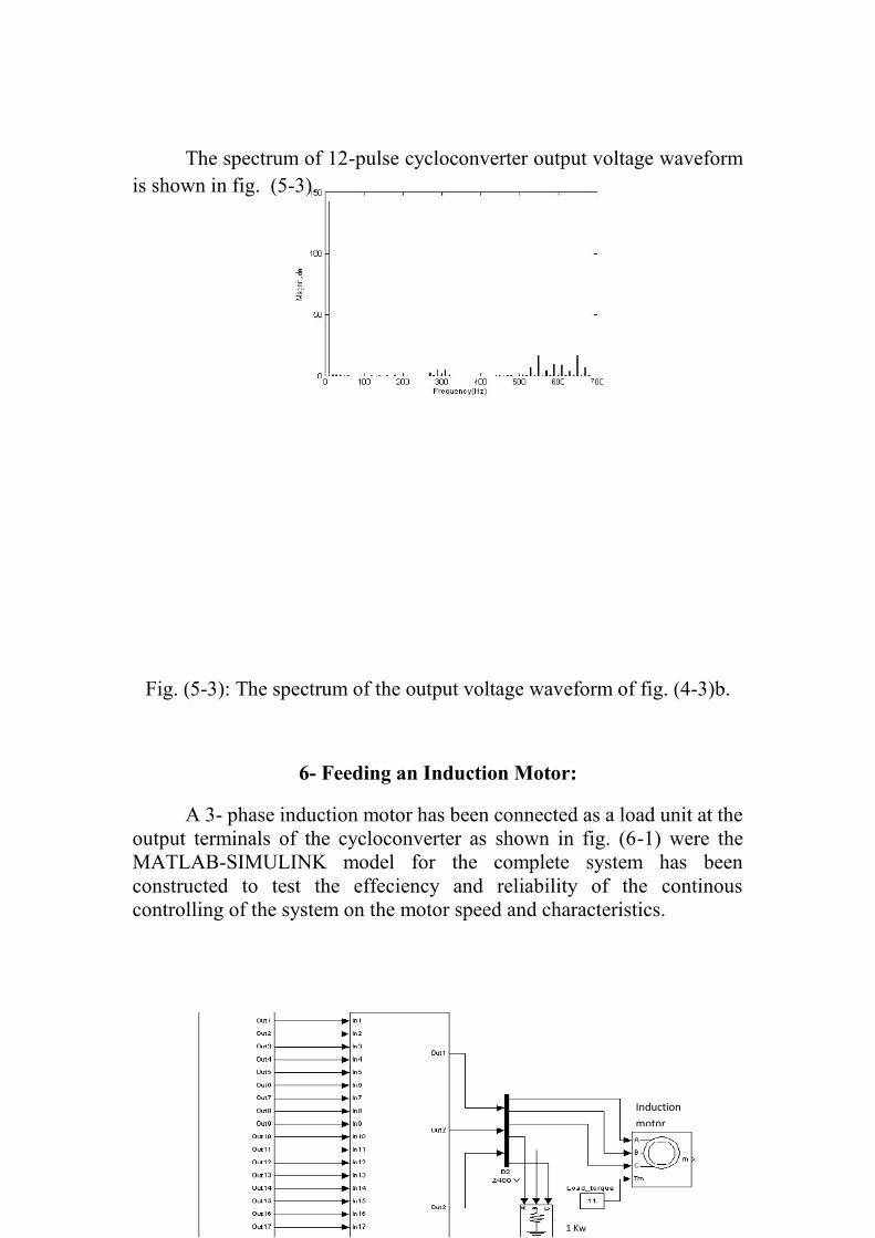
The spectrum of 12-pulse cycloconverter output voltage waveformis shown in fig. (5-3).
Fig. (5-3): The spectrum of the output voltage waveform of fig. (4-3)b.
6- Feeding an Induction Motor:
A 3- phase induction motor has been connected as a load unit at theoutput terminals of the cycloconverter as shown in fig. (6-1) were theMATLAB-SIMULINK model for the complete system has beenconstructed to test the effeciency and reliability of the continouscontrolling of the system on the motor speed and characteristics.

starting
Speedchanging
Fig (6-1): MATLAB-SIMULINK model for the completecycloconverter system feeding an induction motor.
Fig. (6-3) illustrates the starting of the motor then change whichtakes place in motor speed due to changing the output frequency of thecycloconverter from (16.667)Hz to (10)Hz, and fig. (6-4) represents themotor torque.
Fig.(6-3): Online control on motor speed due to (starting) and thenchanging the output frequency.

Fig.(6-4): Motor torque during changing the output frequency.
7- Output Power Factor Correction:
The output power factor has been evaluated by the relationship:
ELn ILn cosLn
P.F = …………………..(3) [4].
( ELn2) ( ILn
2)
Where the output voltage and current waveforms are non-sinusoidal as shown in output waveforms results. Therefore bothdistortion factors of voltage and current should be taken in consideration.
An example to explain the mathmatical analysis for calculation thepower factor for inductive load of (R= 10 ohm, L= 180mH), at outputfrequency of 10Hz. And modulation depth of r= 0.5 for a 3-phase to 3-phase six pulse cycloconverter. From the spectrum analysis of the outputvoltage and current waveforms, following harmonic component appearsas shown below:
n
1
n n
1 1
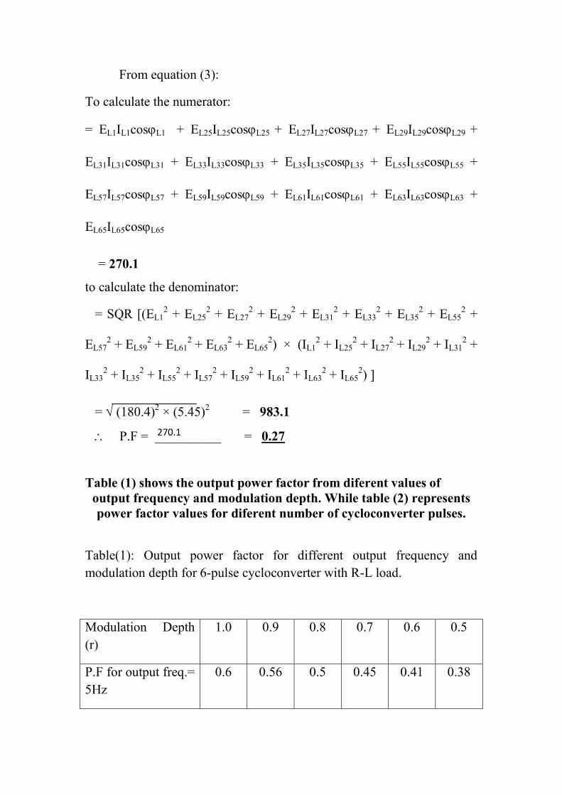
From equation (3):
To calculate the numerator:
= EL1IL1cosL1 + EL25IL25cosL25 + EL27IL27cosL27 + EL29IL29cosL29 +
EL31IL31cosL31 + EL33IL33cosL33 + EL35IL35cosL35 + EL55IL55cosL55 +
EL57IL57cosL57 + EL59IL59cosL59 + EL61IL61cosL61 + EL63IL63cosL63 +
EL65IL65cosL65
= 270.1
to calculate the denominator:
= SQR [(EL12 + EL25
2 + EL272 + EL29
2 + EL312 + EL33
2 + EL352 + EL55
2 +
EL572 + EL59
2 + EL612 + EL63
2 + EL652) × (IL1
2 + IL252 + IL27
2 + IL292 + IL31
2 +
IL332 + IL35
2 + IL552 + IL57
2 + IL592 + IL61
2 + IL632 + IL65
2) ]
= (180.4)2 × (5.45)2 = 983.1
P.F = __________ = 0.27
Table (1) shows the output power factor from diferent values ofoutput frequency and modulation depth. While table (2) representspower factor values for diferent number of cycloconverter pulses.
Table(1): Output power factor for different output frequency andmodulation depth for 6-pulse cycloconverter with R-L load.
Modulation Depth(r)
1.0 0.9 0.8 0.7 0.6 0.5
P.F for output freq.=5Hz
0.6 0.56 0.5 0.45 0.41 0.38
270.1
983.1
P.F for output freq.=10Hz
0.44 0.41 0.38 0.34 0.3 0.27
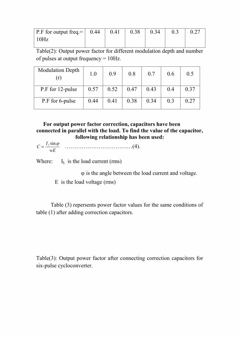
Table(2): Output power factor for different modulation depth and numberof pulses at output frequency = 10Hz.
Modulation Depth(r)
1.0 0.9 0.8 0.7 0.6 0.5
P.F for 12-pulse 0.57 0.52 0.47 0.43 0.4 0.37
P.F for 6-pulse 0.44 0.41 0.38 0.34 0.3 0.27
For output power factor correction, capacitors have beenconnected in parallel with the load. To find the value of the capacitor,
following relationship has been used:
wEIC l sin
………………………………(4).
Where: IL is the load current (rms)
is the angle between the load current and voltage.E is the load voltage (rms)
Table (3) repersents power factor values for the same conditions oftable (1) after adding correction capacitors.
Table(3): Output power factor after connecting correction capacitors forsix-pulse cycloconverter.
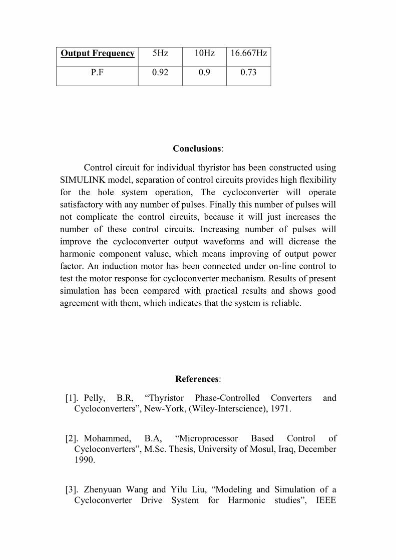
Output Frequency 5Hz 10Hz 16.667Hz
P.F 0.92 0.9 0.73
Conclusions:
Control circuit for individual thyristor has been constructed usingSIMULINK model, separation of control circuits provides high flexibilityfor the hole system operation, The cycloconverter will operatesatisfactory with any number of pulses. Finally this number of pulses willnot complicate the control circuits, because it will just increases thenumber of these control circuits. Increasing number of pulses willimprove the cycloconverter output waveforms and will dicrease theharmonic component valuse, which means improving of output powerfactor. An induction motor has been connected under on-line control totest the motor response for cycloconverter mechanism. Results of presentsimulation has been compared with practical results and shows goodagreement with them, which indicates that the system is reliable.
References:
[1]. Pelly, B.R, “Thyristor Phase-Controlled Converters andCycloconverters”, New-York, (Wiley-Interscience), 1971.
[2]. Mohammed, B.A, “Microprocessor Based Control ofCycloconverters”, M.Sc. Thesis, University of Mosul, Iraq, December1990.
[3]. Zhenyuan Wang and Yilu Liu, “Modeling and Simulation of aCycloconverter Drive System for Harmonic studies”, IEEE

transaction on industrial electronics, Volume 47, Number 3, June2000.
[4]. W. Shepherd and P. Zand, “Energy flow and power factor innonsinusoidal circuits” Cambridge University Press 1979.
[5]. Miyazawa, S. Nakamura, F. and Yamada, N. “EffectiveApproximation Suitable for the Control Algorithm of MicroprocessorBased Cycloconverter”, IEEE Transaction, August 1988.