modeling and simulation of climbing robot -...
TRANSCRIPT

2008
Modelisation
and Simulation of
Climbing Robots
Master Project
Supervisors: Dr. Auke Ijspeert
Dr. Carlo Menon
Simon Ruffieux

This page has been left blank on purpose

Abstract
This project is a part of a bigger project aiming to develop bio-inspired climbing robots
for space exploration. My goal is to provide a tool to simulate the physics of those
robots, design them and test their controllers. Therefore my project is divided into three
main steps.
The first step consists in developing a physical plugin for Webots in order to be able to
simulate the bio-inspired adhesion mechanism that is developed in the research
laboratory.
The second step aims to create 3D models of two different robots in Webots. These
models will reflect as accurately as possible the true mechanics of the ones developed
in the Mechanical Engineering Laboratory of Dr. Carlo Menon at Simon Fraser University.
The first robot will consists in a six-legged spider-like robot with 6 DOFs on each leg. The
second one will consist in a simple four-legged gecko-like robot.
The third step will study the walking mechanisms of the geckos and design a robust
walking pattern using CPG’s with feedback for the gecko robot previously modeled.
More precisely, the study will focus on the mechanism at the level of a legl; how to
optimize the attachment of the leg through adhesion and the reflexes occurring at this
level.
This page has been left blank on purpose

Table of Contents
1 INTRODUCTION .................................................................................................................................................... 1
2 ADHESION PHYSIC PLUG-IN ................................................................................................................................. 2
2.1 INTRODUCTION ................................................................................................................................................. 2
2.2 MODEL OF ATTACHMENT AND DETACHMENT .......................................................................................................... 3
2.2.1 Attachment .............................................................................................................................................. 4
2.2.2 Detachment ............................................................................................................................................. 4 2.2.2.1 Local sheer and stress .....................................................................................................................................4 2.2.2.2 Rupture of adhesion bond ...............................................................................................................................5
2.3 IMPLEMENTATION ............................................................................................................................................. 6
2.3.1 Object classes .......................................................................................................................................... 6
2.3.2 A physics step........................................................................................................................................... 7 2.3.2.1 Collision detection ...........................................................................................................................................8 2.3.2.2 Attachment .....................................................................................................................................................9 2.3.2.3 Detachment.....................................................................................................................................................9
3 ROBOTS MODELISATION ................................................................................................................................... 12
3.1 INTRODUCTION ............................................................................................................................................... 12
3.2 SPIDER ROBOT ................................................................................................................................................ 12
3.2.1 Schema of the spider ............................................................................................................................. 13
3.2.2 Webots model ........................................................................................................................................ 13
3.3 GECKO ROBOT ................................................................................................................................................ 14
4 BIBLIOGRAPHY ................................................................................................................................................... 15

1
1 Introduction
The design of robust space rovers for the exploration of extra-terrestrial planets is a topic
of great interest. These last decades, the idea of using biologically-inspired vehicles for
this purpose is being more and more studied. Indeed animals have evolved for
hundreds of years, their mechanical and control systems are able to deal with all sorts of
situations and resist strong perturbations. It is then natural to try to mimic their capacity in
order to design robust vehicles able to face the wrecked grounds of extra-terrestrial
planets.
The main idea of this project is to take inspiration of the adhesion mechanism of the
geckos which is bla bla bla and develop with this mechanism small robots that could
climb and face any wrecked ground.
Develop:
Previous robotics project (geckos, esa spider)
Adhesion mechanism
Reflex single leg level , Muscles–spindles, GTO
CPG oscillators

2
2 Adhesion physic plug-in
2.1 Introduction
The Webots simulation program does not implement any adhesion mechanism in its
actual version. However it allows the user to define specific physics plugins and thus
the modification of the physic properties of any object of the simulation, the
addition of new forces or, more generally, the modelisation of new behaviors for all
or any particular objects of the simulation. This also allows the user to define
particular handmade sensors or other actuators that do not actually exist in Webots.
Therefore, an adhesion model should be defined in order to create the plugin for
Webots.
The accurate modelisation of the adhesion mechanism is a key part of this project.
Simulations and optimizations of the different gaits of the robots rely mainly on an
accurate model of this mechanism. Many recent studies have described the
adhesion and friction in gecko toe attachment and detachment. (Autumn,
Dittmore, Santos, Spenko, & Cutkosky, 2006) (Autumn & Peattie, 2002) (Tian, et al.,
2006). Most of these studies review the mechanism occurring at a nano-scale, like
the attachment or detachment of single setae and spatulae (nano-hair) and the
force acting at this level. (maybe put a picture here). Most of these papers also
study the maximum pulling force that geckos can handle or the maximum pulling
angle before detachment. However fewer papers try to define an accurate macro-
scale model that could be used for our simulation. The ESA report (cf ESA) defines a
mechanical and elastic model of the adhesion system of spider. They developed a
model based on the hierarchical adhesion structure that gives the ability to spiders
and geckos to adapt to different surfaces. In this report they model each spatula by
a spring element that can bend and store energy. Then the adhesion force is
opposed to the elastic force in each spatula, yielding a discretized model of the
forces along the contact surface. When pulling, the elastic force opposes to the
adhesion force and leads at a certain point to the rupture of the contact between
springs (spatula) and surface, thus leading to a progressive detachment of the
entire surface. The idea of modeling local forces will be kept in this paper, however
with a different approach than the spring model. Indeed the spring model is used
particularly to reflect the adhesion on rough surface; however in our simulations only
the ideal case of flat surfaces is considered.
Most of the papers reviewed focus on a close modeling on the adhesion
characteristics of the animals. However in this paper we are trying to model the
main characteristics and adhesion properties of the dry adhesive developed here
for the purpose of the robot. (link to Dan Sameoto’s defense thesis).
The developed model also has to take into account some the limitation induced by
Webots and some simplification in order to keep the computational time

3
reasonable. The main idea of the Webots plugin implemented in this paper is to
extend the collision detection only for the sticky objects; if a sticky object collides
any surface, the collision is analyzed and the two objects are potentially glued
together to simulate the adhesion. Then the sheer and stress forces are analyzed
locally to model a realistic detachment behavior.
2.2 Model of attachment and detachment
The attachment mechanism of the dry adhesive is relatively simple; a good angle of
approach in order to maximize the contact surface and some pressure are the two
key elements to obtain a good attachment. Furthermore, the maximum adhesion
force is obtained after a few delay, required for the dry adhesive to completely
adhere the surface.
The detachment mechanism, in the contrary, is much more complicated. It
depends on many factors such as pulling angle, peeling mechanism, the size of the
contacting surface area and particularly the stress and sheer occurring on the local
areas of the surface. Webots cannot retrieve such local data, but is able to retrieve
the forces and moments acting on a joint; in our case the equivalent of the ankle
joint; its position is represented by a red dot on Figure 1; with those data, a
mathematical model can be developed to determine the forces occurring at each
point of the interface between the paw and the ground surface. This allows us to
model more accurately the detachment mechanism.
Figure 1: Lateral and top view of an object (blue) colliding a surface (green)
with the frame axis of the object.
On the figure above, we can see the frame axis, relative to the object, used for
the model. The pulling or pressing force and the moments acting on the object are
retrieved at the top of the object (red point) and used to compute the sheer and
stress locally at the interface.
x
z
z

4
Note the model described here assumes a robotic application and particularly
legged robots; therefore in this particular case, as it is not possible in Webots to
directly retrieve the forces acting on the object, the easiest way to obtain the
forces acting on a paw is to retrieve the force acting on the ankle joint linking the
adhering object (paw) and the end-leg. Note that this ankle joint could be
replaced by an unmovable joint whose only purpose would be to retrieve the
required information for any other cases.
2.2.1 Attachment
Still To define (real experiments are being done in the lab)
modify number of contacting points according to:
(I would say according to speed, angle of approach and [contacting surface?])
And rapidly increasing while no pulling force !
2.2.2 Detachment
2.2.2.1 Local sheer and stress
In this section a model of the forces occurring at the interface between the paw
and the ground is described. We make the strong assumption to consider the
paws as rigid bodies on which some forces and torque occurs and the adhesion
bonds are considered as cantilever beams. With respect to those assumptions, we
can compute the sheer and stress occurring locally on each beam along the
contacting surface.
The three following equations define the local stress ( ) and sheer ( ) along
the contacting surface. Those equations will be used to determine locally if the
adhesion is holding by simulating the forces acting at each points of the surface.
(2)
(3)
(4)
where are the forces acting on the object along each axis (shown on Figure
1), are the moments acting on the object along the x and z axis and finally
and are the width and height of the contacting surface.
5
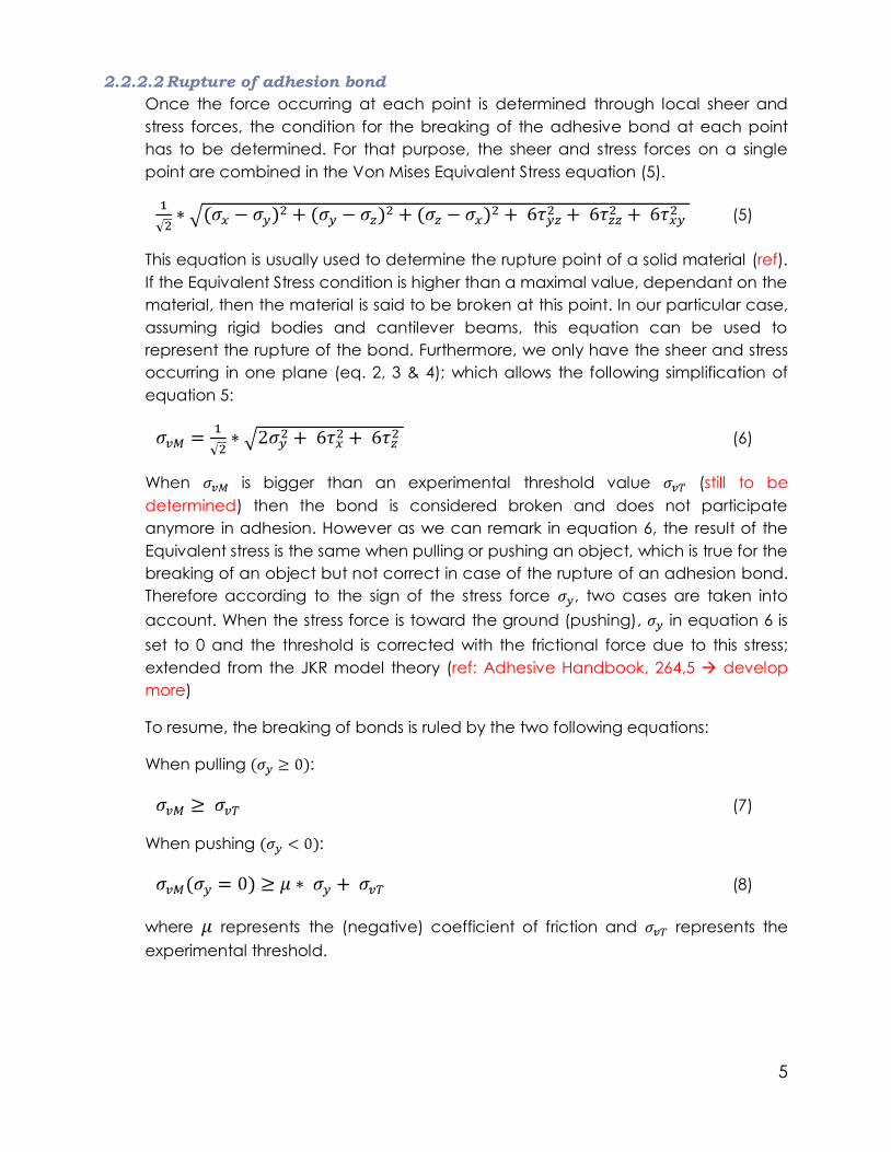
2.2.2.2 Rupture of adhesion bond
Once the force occurring at each point is determined through local sheer and
stress forces, the condition for the breaking of the adhesive bond at each point
has to be determined. For that purpose, the sheer and stress forces on a single
point are combined in the Von Mises Equivalent Stress equation (5).
(5)
This equation is usually used to determine the rupture point of a solid material (ref).
If the Equivalent Stress condition is higher than a maximal value, dependant on the
material, then the material is said to be broken at this point. In our particular case,
assuming rigid bodies and cantilever beams, this equation can be used to
represent the rupture of the bond. Furthermore, we only have the sheer and stress
occurring in one plane (eq. 2, 3 & 4); which allows the following simplification of
equation 5:
(6)
When is bigger than an experimental threshold value (still to be
determined) then the bond is considered broken and does not participate
anymore in adhesion. However as we can remark in equation 6, the result of the
Equivalent stress is the same when pulling or pushing an object, which is true for the
breaking of an object but not correct in case of the rupture of an adhesion bond.
Therefore according to the sign of the stress force , two cases are taken into
account. When the stress force is toward the ground (pushing), in equation 6 is
set to 0 and the threshold is corrected with the frictional force due to this stress;
extended from the JKR model theory (ref: Adhesive Handbook, 264,5 develop
more)
To resume, the breaking of bonds is ruled by the two following equations:
When pulling :
(7)
When pushing :
(8)
where represents the (negative) coefficient of friction and represents the
experimental threshold.
6
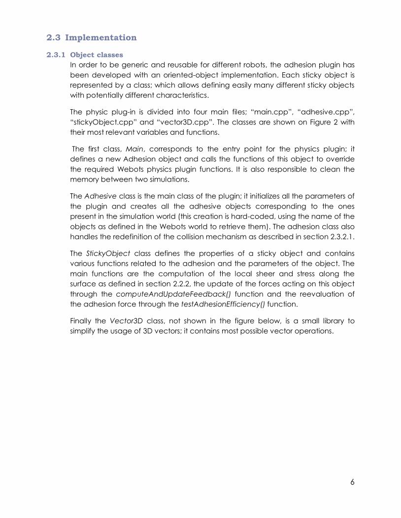
2.3 Implementation
2.3.1 Object classes
In order to be generic and reusable for different robots, the adhesion plugin has
been developed with an oriented-object implementation. Each sticky object is
represented by a class; which allows defining easily many different sticky objects
with potentially different characteristics.
The physic plug-in is divided into four main files; “main.cpp”, “adhesive.cpp”,
“stickyObject.cpp” and “vector3D.cpp”. The classes are shown on Figure 2 with
their most relevant variables and functions.
The first class, Main, corresponds to the entry point for the physics plugin; it
defines a new Adhesion object and calls the functions of this object to override
the required Webots physics plugin functions. It is also responsible to clean the
memory between two simulations.
The Adhesive class is the main class of the plugin; it initializes all the parameters of
the plugin and creates all the adhesive objects corresponding to the ones
present in the simulation world (this creation is hard-coded, using the name of the
objects as defined in the Webots world to retrieve them). The adhesion class also
handles the redefinition of the collision mechanism as described in section 2.3.2.1.
The StickyObject class defines the properties of a sticky object and contains
various functions related to the adhesion and the parameters of the object. The
main functions are the computation of the local sheer and stress along the
surface as defined in section 2.2.2, the update of the forces acting on this object
through the computeAndUpdateFeedback() function and the reevaluation of
the adhesion force through the testAdhesionEfficiency() function.
Finally the Vector3D class, not shown in the figure below, is a small library to
simplify the usage of 3D vectors; it contains most possible vector operations.

7
Figure 2: Object representation
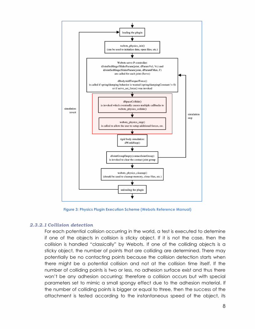
2.3.2 A physics step
The execution scheme of a physics plugin by Webots is shown on Figure 3, with
the four main functions of a simulation step; the update of the servos with the
addition of the forces, the detection and handling of the potential collisions, the
step function to advance the world state of a time Δt and finally the suppression
of the joints created to handle the collisions contact.
The adhesive physics plugin implemented in this paper mainly redefines the
collision detection during the webots_physics_collide() function and modifies the
collision behavior for the adhesive objects. Then the plugin modify the behavior
of these objects in the webots_physic_step() function to simulate the adhesion
mechanism.
Main
void webots_physic_step()
int webots_physics_collide(g1,g2)
void webots_physics_cleanup()
void webots_physics_draw()
void Webots_physics_predraw()
Adhesive *adhe_physics
StickyObject
void attach()
void detach()
void computeContactArea()
void computeAndUpdateFeedback()
void testAdhesionEfficiency()
int isAttached()
Vector3D computeSheerAndStress(x,z)
const char* name
dGeomID geomID
dBodyID bodyID
dReal mass
dReal surfaceArea
int attached
int adheringPoints
dJointID adhesionJoint
dJointID linkJoint
Vector3D adhesiveForce
Vector3D linkJointForce
Vector3D linkJointTorque
Adhesive
void step()
int collision(g1, g2)
void handleCollisionSticky(g1, g2)
const char* stickyObjNames[]
StickyObject *stickObj[]
8
Figure 3: Physics Plugin Execution Scheme (Webots Reference Manual)
2.3.2.1 Collision detection
For each potential collision occurring in the world, a test is executed to detemine
if one of the objects in collision is sticky object. If it is not the case, then the
collision is handled “classically” by Webots. If one of the colliding objects is a
sticky object, the number of points that are colliding are determined. There may
potentially be no contacting points because the collision detection starts when
there might be a potential collision and not at the collision time itself. If the
number of colliding points is two or less, no adhesion surface exist and thus there
won’t be any adhesion occurring; therefore a collision occurs but with special
parameters set to mimic a small spongy effect due to the adhesion material. If
the number of colliding points is bigger or equal to three, then the success of the
attachment is tested according to the instantaneous speed of the object, its
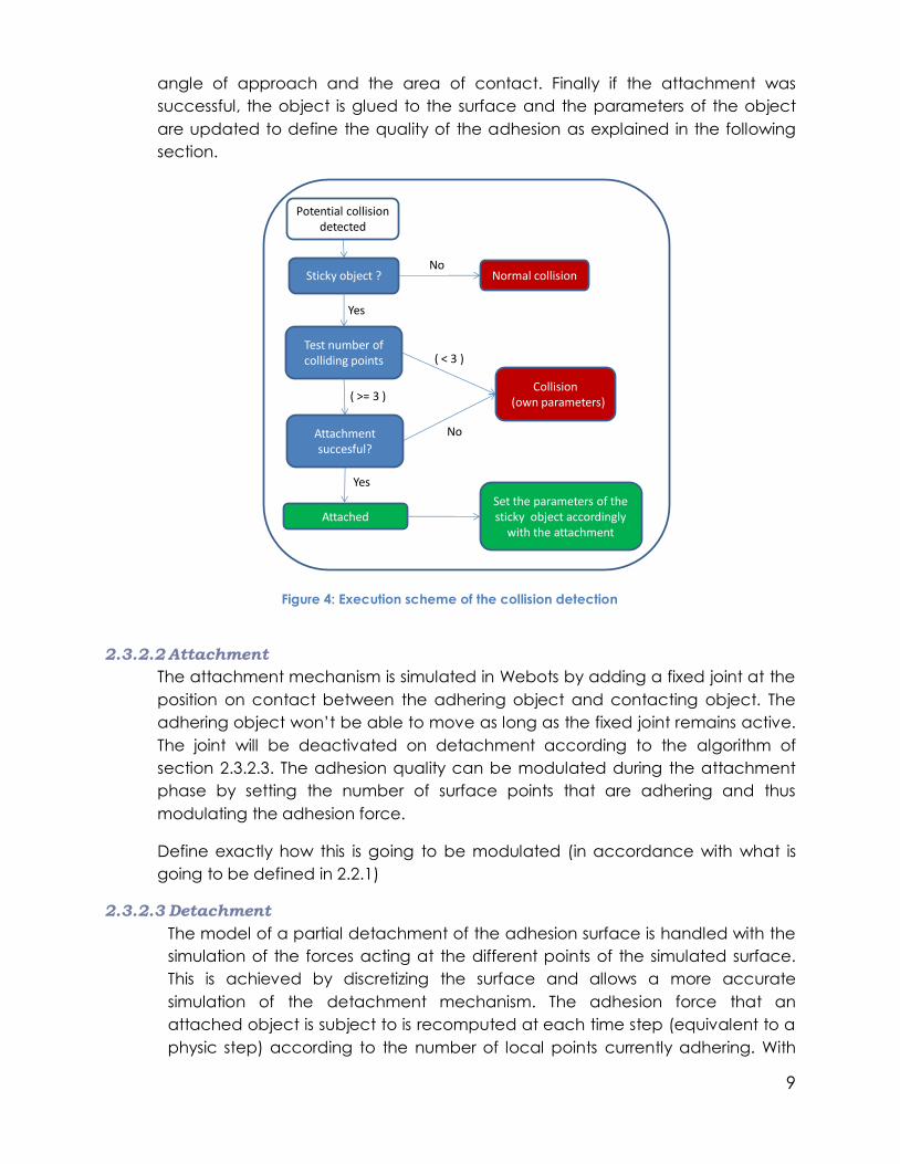
9
angle of approach and the area of contact. Finally if the attachment was
successful, the object is glued to the surface and the parameters of the object
are updated to define the quality of the adhesion as explained in the following
section.
Figure 4: Execution scheme of the collision detection
2.3.2.2 Attachment
The attachment mechanism is simulated in Webots by adding a fixed joint at the
position on contact between the adhering object and contacting object. The
adhering object won’t be able to move as long as the fixed joint remains active.
The joint will be deactivated on detachment according to the algorithm of
section 2.3.2.3. The adhesion quality can be modulated during the attachment
phase by setting the number of surface points that are adhering and thus
modulating the adhesion force.
Define exactly how this is going to be modulated (in accordance with what is
going to be defined in 2.2.1)
2.3.2.3 Detachment
The model of a partial detachment of the adhesion surface is handled with the
simulation of the forces acting at the different points of the simulated surface.
This is achieved by discretizing the surface and allows a more accurate
simulation of the detachment mechanism. The adhesion force that an
attached object is subject to is recomputed at each time step (equivalent to a
physic step) according to the number of local points currently adhering. With
Sticky object ? Normal collisionNo
Test number of colliding points
Yes
Potential collision detected
Collision(own parameters)
( < 3 )
( >= 3 )
No
Yes
AttachedSet the parameters of the sticky object accordingly
with the attachment
Attachmentsuccesful?

10
such a mechanism, as soon as some points begin to detach, the adhesion force
decreases and at the next simulation step, more points will detach due to the
adhesion force being smaller. Remark that the maximum number of points used
to simulate a surface can be modified according to the number of adhering
objects of the simulation and the computer capabilities in order to be able to
tune between an acceptable computation time and a more accurate model.
The implementation of the algorithm used in the adhesion plugin is shown on
Figure 5. Note that the loop “For(everyLocalPoint of the object)” represents a
loop over all the contacting surface in the x and z direction (cf. Figure 2) to
simulate all the points of the 2D surface.
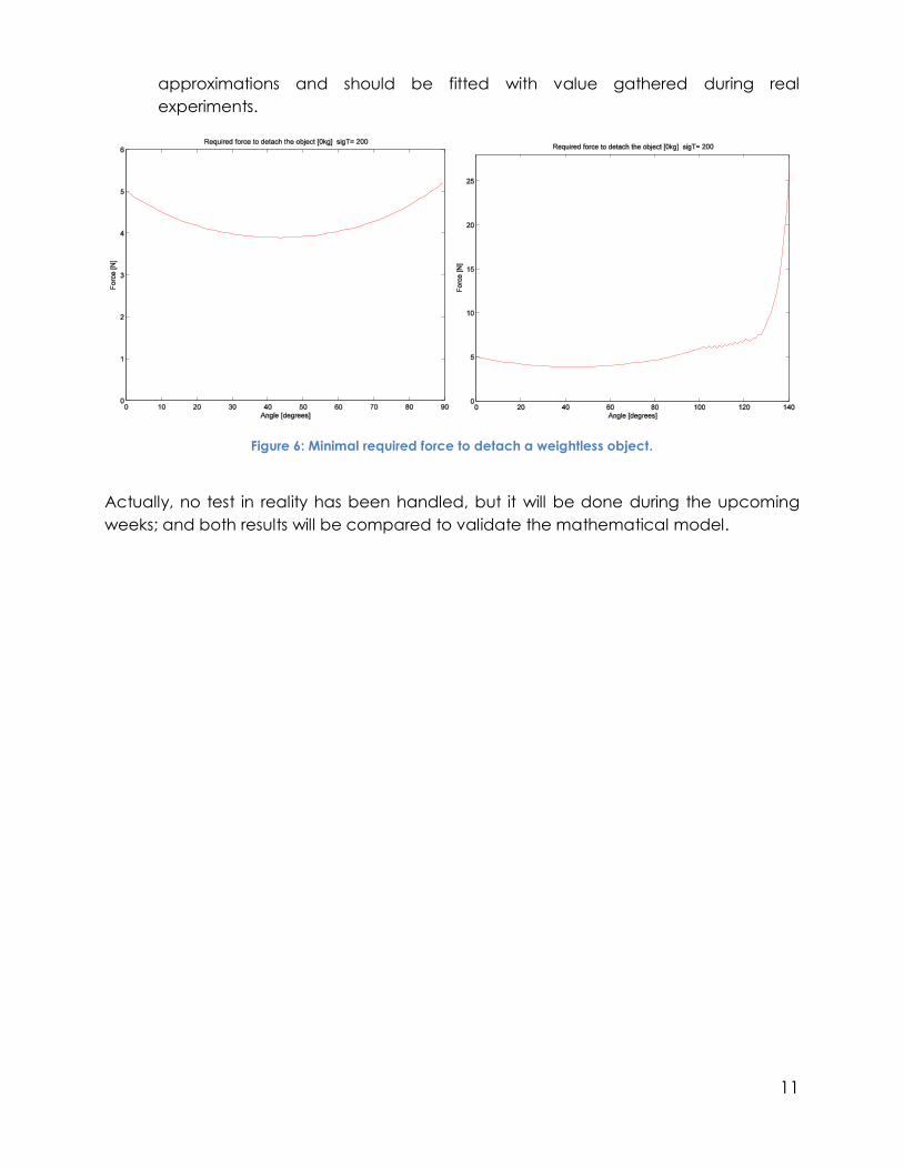
A simple test to plot the minimal force required to detach a weightless object has
been handled in order to be able to compare the behavior of the model with
reality. A weightless sticky cube is static on a flat surface and an increasing force
is pulling the cube object through a constant angle. The minimal force required
to detach the object is recorded for different pulling angles. The result is shown
on Figure 6. Note that an angle of 0 degree represents a vertical pulling force
and an angle of 90 degrees a horizontal pulling force. We can observe that the
optimal pulling angle is 45 degrees and that the required force is growing when
pulling from 85-90 degrees. The force required when partially pushing the object
(>90 degrees) rapidly increase after some oscillation between 100-125 degrees.
These oscillation have to be better studied to understand their origin. Note that
the values of the equations have been set to empirical data gathered by Dan
Sameoto while working on the dry adhesive; those vealue are rough
At each physic step, Do:
For(every sticky object attached)
#attachedPoints = MAX_ATTACHEDPOINTS
For(everyLocalPoint of the object)
computeLocalSheerAndStress(x,z)
If(func(localSheerAndStress) > threshold)
#attachedPoints = #attachedPoints-1
endIf
endFor
updateAdhesionForce(#attachedPoints)
endFor
endDo
Figure 5: Detachment algorithm
11
approximations and should be fitted with value gathered during real
experiments.
Figure 6: Minimal required force to detach a weightless object.
Actually, no test in reality has been handled, but it will be done during the upcoming
weeks; and both results will be compared to validate the mathematical model.

12
3 Robots modelisation (DRAFT)
3.1 Introduction
Two different robots will be modelised for the Webots simulation. The first one, a
spider robot, will accurately reflect the robot actually developed by Yasong Li in
Carlo Menon’s laboratory at SFU.
Then a simple gecko-like robot has been modeled in order to study closer the
adhesion of a paw and how to improve this crucial step. (Further chapter, coming
soon). This robot will not reflect any real robot, but will be inspired by biology and
extremely simple to allow a close study of the leg and foot mechanism without
having to worry too much about the behavior of a complex body.
3.2 Spider robot
3.2.1 Real spider robot
The spider robot is a 6-legged robot. It has been specially designed with a light
weight structure in order to be able to climb walls. Each of its legs has 3-DOF and a
compliant joint at the level of the ankle in order to maximize the contact surface
of the paws to the ground. Each paw has a sticky material that allows the spider to
adhere to surfaces. As we can see on Figure 7, the spider is still under development
and all its structure is not fully defined. The feet are particularly of higher
importance for the robustness of the robot. Indeed the feet are one of the key part
of the attachment mechanism and should as much as possible facilitate the
adhesion of the paws. Therefore different structures are still investigated.
Furthermore the motors currently used should be replaced in long-term by
hydraulic motors. Also the initial idea is to have all the motors on the central
platform of the spider instead of the actual version where some of the motors are
at the position of the knees.
Figure 7: Photo of the spider robot (temporary picture)
13
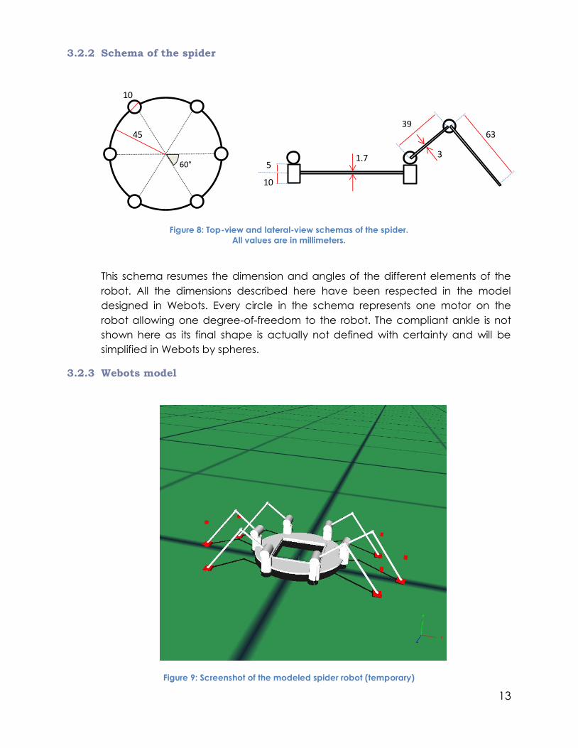
3.2.2 Schema of the spider
Figure 8: Top-view and lateral-view schemas of the spider.
All values are in millimeters.
This schema resumes the dimension and angles of the different elements of the
robot. All the dimensions described here have been respected in the model
designed in Webots. Every circle in the schema represents one motor on the
robot allowing one degree-of-freedom to the robot. The compliant ankle is not
shown here as its final shape is actually not defined with certainty and will be
simplified in Webots by spheres.
3.2.3 Webots model
Figure 9: Screenshot of the modeled spider robot (temporary)
60°
45
10
1.75
10
3963
3

14
The model realized in Webots is a mixture of the current design and the final
designed design. Therefore, the shape of the knees servos has been omitted and
the weight of the legs can be assumed to be negligible; however the paws will still
have some weight. Furthermore the paws have been modeled as simple spheres
for two reasons; the first one is to simplify the simulation as simulating a 3 DOF ankle
with a elastic paw during the simulation would be quite unhandy and it would be
difficult to obtain a good behavior with this scheme. The second reason is that the
design of the paws is not fully defined and that the attachment and detachment
mechanisms of these paws are actually being included directly into the
mathematical model of adhesion to be able to reflect more accurately the real
mechanism independently of the simulation.
Note that figure 9 is an old design where the feet are modeled as cube and not as
spheres. It also has the 3 DOF ankles yielding some ground adaptation problems
during the simulation.
3.3 Gecko robot
Still to be modeled

15
4 Bibliography
Autumn, K., & Peattie, A. (2002). Mechanims of Adhesion in Geckos. Integrative and
Comparative Biology. Anaheim.
Autumn, K., Dittmore, A., Santos, D., Spenko, M., & Cutkosky, M. (2006). Frictional
adhesion: a new angle on gecko attachment. Experimental Biology (209), 3569-3579.
Autumn, K., Hsieh, S., Dudek, D., Chen, J., Chitaphan, C., & Full, R. (2006). Dynamics of
geckos running vertically. Experimental Biology (209), 260-272.
Ellery, A., Scott, G., Husbands, P., Gao, Y., Vincent, J., Vaughan, E., et al. (2005). Bionics
& Space Sytems Design: Case Study 1 - Mars Walker. ESA.
Shan, J., Mei, T., Ni, L., Chen, S., & Chu, J. Fabrication and Adhesive Force Analysis of
Biomimetic Gecko Foot-Hair Array.
Tian, Y., Pesika, N., Zeng, H., Rosenberg, K., Zhao, B., McGuiggan, P., et al. (2006).
Adhesion and Friction in gecko toe attachment and detachment. PNAS , 103 (51),
19320-19325.
Webots Reference Manual. (n.d.). Retrieved 2008, from www.cyberbotics.com:
http://www.cyberbotics.com/cdrom/common/doc/webots/reference/reference.html