modeling and parameter identification of a dc motor using ... · both the matlab system...
TRANSCRIPT
IOSR Journal of Mechanical and Civil Engineering (IOSR-JMCE)
e-ISSN: 2278-1684,p-ISSN: 2320-334X, Volume 13, Issue 6 Ver. II (Nov. - Dec. 2016), PP 46-56
www.iosrjournals.org
DOI: 10.9790/1684-1306024656 www.iosrjournals.org 46 | Page
Modeling and Parameter Identification of a DC Motor Using
Constraint Optimization Technique
Surajudeen Adewusi1
1(Mechanical Engineering Department, Jubail University College, Royal Commission for Jubail and Yanbu,
P. O. Box 10074, Jubail Industrial City 31961, Saudi Arabia).
Abstract: This paper presents mathematical modeling and simulation, and experimental study of an
electromechanical system (a direct current motor) to identify the mechanical and electrical parameters (mass
moment of inertia, damping, armature resistance and motor constant) of the motor and its accessories.
Laboratory experiments were performed to obtain the step responses of the motor. The parameters were
identified in two stages viz: 1) determination of the time constant and gain of the first order transfer function of
the motor’s model using MATLAB Parameter Identification Toolbox. 2) MATLAB codes were written to invoke
MATLAB Constraint Optimization Toolbox and minimize the root mean squared error between the experimental
and simulated step responses using the relationships between the motor parameters and the time constant and
gain as constraint equations. The comparisons between the experimental and simulated step responses showed
excellent agreement. The mechanical and electrical parameters of the motor were found to be the following:
mass moment of inertia = 9.85 x 10⁻³
kgm2, armature resistance = 6.29 Ohms, damping = 2.52 x 10
-3 Nms/rad,
and motor constant = 1.57 x 10⁻²
Nm/Amp. Keywords: dc motor model, constraint optimization, parameter identification, time constant, step response.
Nomenclature
DC Direct current
ν(t) The motor's input voltage (Volts).
R The motor's armature resistance (Ohms).
L The armature's inductance (Henry)
i The armature's current (Amp)
km DC motor constant (Nm/Amp.)
vb The motor's back electromotive force (emf) (Volts).
τm Motor’s supplied torque (Nm)
T Time constant (seconds)
b Damping of the DC motor and accessories (Ns/rad).
I Mass moment of inertia of the flywheel (kgm2).
J Combined mass moment of inertia of the flywheel and shaft and armature (kgm2).
1G Motor gain or proportionality constant
ω Angular speed (rad/s)
PI Proportional and integral controller
TQ TecQuipment (Trademark for servo motor manufacturer)
I. Introduction Electromechanical devices (DC and alternating current motors) are widely used as prime movers for
mechanical systems and machines. In some cases where automation and/or control of the mechanical systems is
required, a control unit is attached to the electric motors and these type of motors are generally referred to as
servo motor. Due to the importance of the servo motors in the automation of systems and processes, research
studies on the characterization, mathematical modeling and parameter identification of electromechanical
devices have been published [1-6]. Modeling and simulation of physical systems, a realistic compromise, are
widely used in engineering for better understanding of the characteristics of systems in order to control and/or
improve systems’ performance and reduce costs by building and testing a prototype at the preliminary stage
instead of the exact machine. The concepts of modeling and parameter identification are more useful during
modification of existing systems when little or no information about the existing system is available. This paper
is the outcome of the author’s efforts during the development of laboratory manual for Systems Dynamic and
Control course at the Department of Mechanical Engineering, Jubail University College, Saudi Arabia. The
manual for the TQ servo trainer contains no information about the mechanical and electrical parameters or
Modeling and Parameter Identification of a DC Motor Using Constraint Optimization Technique
DOI: 10.9790/1684-1306024656 www.iosrjournals.org 47 | Page
properties of the system, which are needed to teach students about designing and testing of PI controller for
servo motor to simulate speed control and responses.
The mechanical and electrical properties of electromechanical devices are needed to derive
mathematical models. Even if these parameters are documented in the user manuals, it may be necessary to
determine them if the system has been used for a few years. The reason for this is that these parameters will
change due to aging, wear and tear of the system. Different parameter identification techniques and algorithms
have been developed and used by different researchers to determine some important mechanical and electrical
properties of various models of electromechanical systems. For examples, a multi-objective elitist genetic
algorithm has been used to minimize the error between the model and measured responses of a DC motor [7].
Artificial Neutral Network has also been used to determine model parameters and control dynamic systems [8].
One of the advantages of neutral network is that parameter identification could be done online while the system
is working by using adaptive learning method. Furthermore, a parameter estimation method using a block pulse
function has been used to determine the parameters of DC servo motor systems [9]. The block pulse
approximates a function as a linear combination of sets of orthogonal basis functions. The most common
technique for parameter identification is the least square error (LSE) method [10]. LSE involves the
minimization of the sum of the squared error between the model and experimental responses.
It should be noted that the different methods of model parameter identification reported [1, 2, 3, 5, 10]
are similar to a curve fitting, which involves changing the model parameters until a good match between the
model and experimental responses is achieved. However, it is well-known that curve-fitting technique has
multiple solutions. This means that there are infinite sets of values that would yield a good match between the
model and experimental responses. Therefore, care needs to be taken to ensure that the obtained set of
parameters are realistic, that is the parameters can give a unique solution, which can be related to the actual
physical system. A unique solution implies that regardless of the assumed initial parameters while solving the
error minimization of the model and experimental responses, the final values of the parameters will always be
the same. One of the ways to ensure the uniqueness of the identified parameters is by using constraint
optimization method, which checks the relationship between the parameters in addition to the minimization of
error between experimental and simulated responses. The constraint optimization technique has been used in the
parameter identification of models for the human hand-arm system [11]. The reported studies [1, 2, 3, 5, 10] did
not check the uniqueness of the identified parameters. The present study uses constraint optimization technique
in addition to the conventional root-mean-square error method in order to ensure that the identified DC motor
parameters yield unique solution.
In this study, the mechanical and electrical parameters (mass moment of inertia, damping, armature
resistance and motor constant) of an electromechanical device (TQ DC servo motor and accessories) are
determined from a linear model of the system and experimental responses of the device. Both the MATLAB
System Identification and Constraint Optimization Toolboxes are used for the parameter identification of the
model for the electromechanical device in order to ensure the uniqueness of the identified parameters. The
parameters of the electromechanical device are needed in order to design and simulate a PI controller for speed
control of the DC motor for demonstration to students in Systems Dynamic and Control course.
II. Methods 2.1 Experimental Set-up
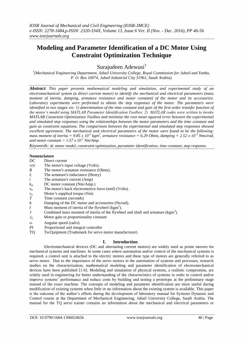
Figure 1 shows the electromechanical device that was used in the present study, the TecQuipment (TQ)
CE110 Servo Trainer Apparatus [12, 13]. The CE110 Servo Trainer Apparatus is designed for DC servo motor
speed and position control using a typical PID controller (TQ CE 120 Controller). The relevant parts of the
apparatus, shown in Fig. 1, for the experiment comprises a DC motor, a DC generator and a flywheel mounted
on a common shaft. An analogue input signal to the motor circuit in the range 0 to ±10V enables variable shaft
speed of rotation in either direction to be achieved. Shaft speeds, up to 1999 revolutions per minute (RPM), are
continually sensed optically and indicated on a panel mounted digital meter. An analogue voltage signal
proportional to speed, in the range 0 to ±10V, is available at an adjacent socket. The DC motor may be loaded,
statically or dynamically, using the DC generator. The full range of loads may be applied by inputting an
analogue voltage in the range 0 to 10V. This electronically varies the load on the generator. The DC generator
was not used in the present study.
The CE 110 servo trainer has two additional removable inertia discs which may be added to the
flywheel permanently fixed on the common shaft. An electrically operated clutch, enabled by a toggle switch, is
used to study angular position responses by engaging an output shaft via a 30:1 reduction gearbox. The
apparatus may also be used for the practical introduction into the design, operation and application of controllers
with linear and non-linear parameters and inputs.
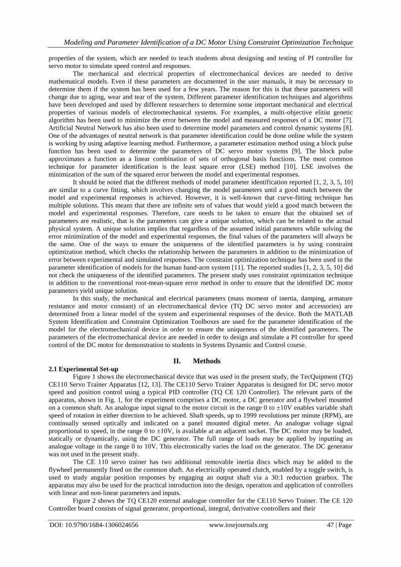
Figure 2 shows the TQ CE120 external analogue controller for the CE110 Servo Trainer. The CE 120
Controller board consists of signal generator, proportional, integral, derivative controllers and their
Modeling and Parameter Identification of a DC Motor Using Constraint Optimization Technique
DOI: 10.9790/1684-1306024656 www.iosrjournals.org 48 | Page
(a)
(b)
Figure 1: (a) TQ CE110 Servo Trainer; (b) schematic diagram of the servo trainer showing all components.
Figure 2: TQ CE 120 analogue controller.
Modeling and Parameter Identification of a DC Motor Using Constraint Optimization Technique
DOI: 10.9790/1684-1306024656 www.iosrjournals.org 49 | Page
combinations, and other accessories necessary to build either an open loop or closed loop control actions for the
CE 110 servo trainer. Since all of the power supplies for the built-in devices and systems are included, only low
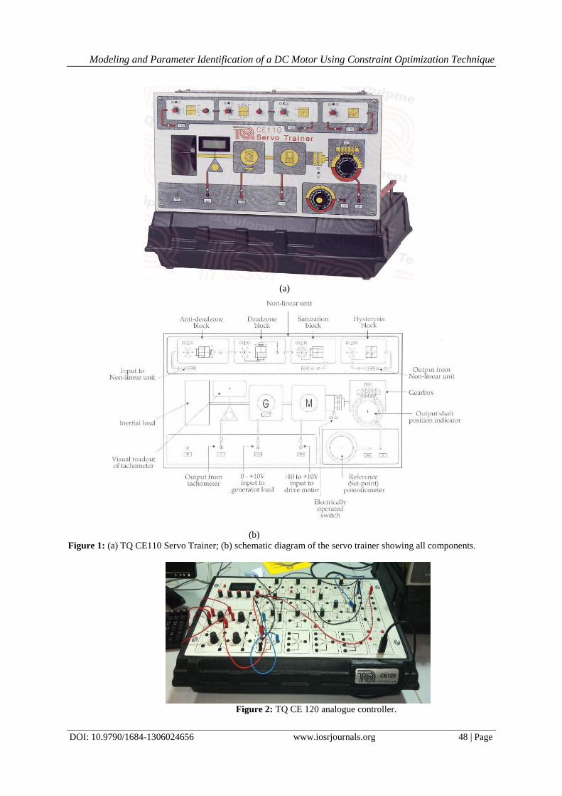
power (0 to ±10V) connections between the CE110 and the external controller are required. Finally, Fig. 3
shows the PC in which the TQ CE2000 software is installed for input and output data acquisitions, analysis,
display and storage. The CE 2000 software has a dongle without which the software will not work.
Figure 3: PC with CE 2000 software to measure and display responses of the DC servo motor.
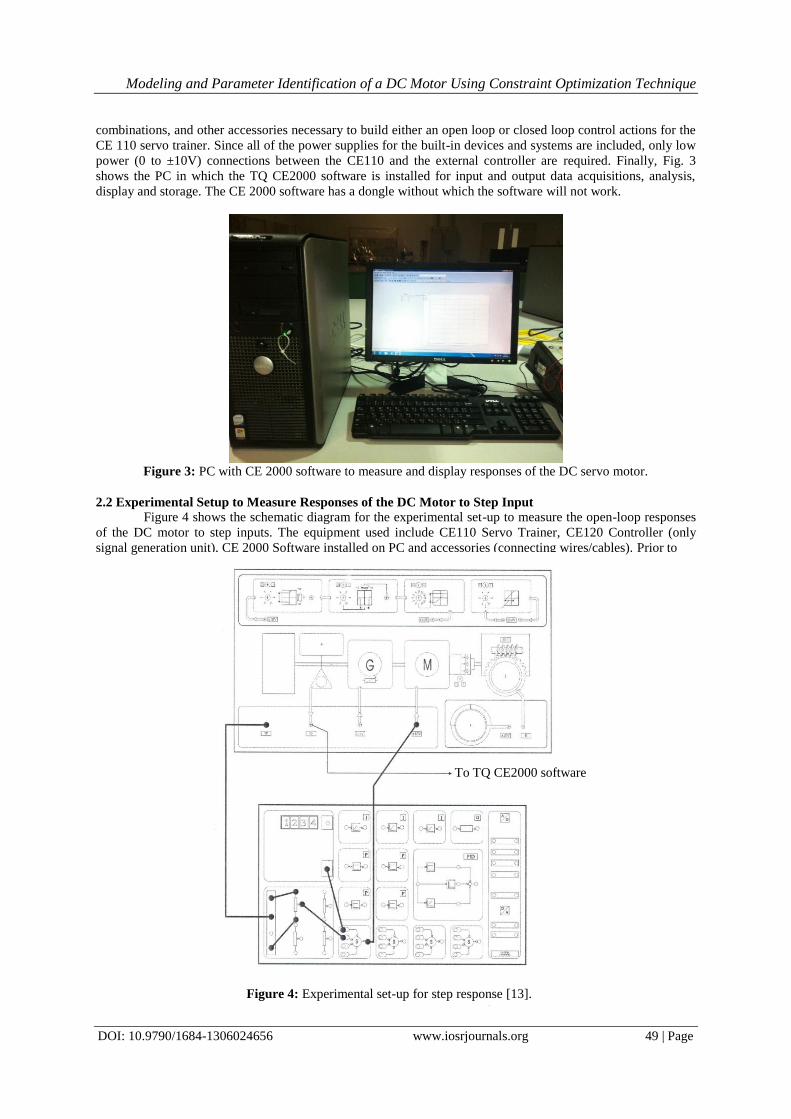
2.2 Experimental Setup to Measure Responses of the DC Motor to Step Input
Figure 4 shows the schematic diagram for the experimental set-up to measure the open-loop responses
of the DC motor to step inputs. The equipment used include CE110 Servo Trainer, CE120 Controller (only
signal generation unit), CE 2000 Software installed on PC and accessories (connecting wires/cables). Prior to
To TQ CE2000 software
Figure 4: Experimental set-up for step response [13].
Modeling and Parameter Identification of a DC Motor Using Constraint Optimization Technique
DOI: 10.9790/1684-1306024656 www.iosrjournals.org 50 | Page
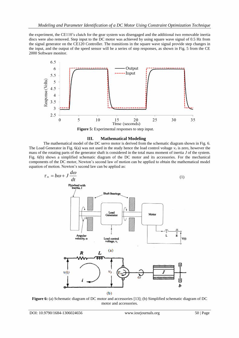
the experiment, the CE110’s clutch for the gear system was disengaged and the additional two removable inertia
discs were also removed. Step input to the DC motor was achieved by using square wave signal of 0.5 Hz from
the signal generator on the CE120 Controller. The transitions in the square wave signal provide step changes in
the input, and the output of the speed sensor will be a series of step responses, as shown in Fig. 5 from the CE
2000 Software monitor.
Figure 5: Experimental responses to step input.
III. Mathematical Modeling The mathematical model of the DC servo motor is derived from the schematic diagram shown in Fig. 6.
The Load Generator in Fig. 6(a) was not used in the study hence the load control voltage v1 is zero, however the
mass of the rotating parts of the generator shaft is considered in the total mass moment of inertia J of the system.
Fig. 6(b) shows a simplified schematic diagram of the DC motor and its accessories. For the mechanical
components of the DC motor, Newton’s second law of motion can be applied to obtain the mathematical model
equation of motion. Newton’s second law can be applied as:
dt
dJbm
(1)
Figure 6: (a) Schematic diagram of DC motor and accessories [13]; (b) Simplified schematic diagram of DC
motor and accessories.
Modeling and Parameter Identification of a DC Motor Using Constraint Optimization Technique
DOI: 10.9790/1684-1306024656 www.iosrjournals.org 51 | Page
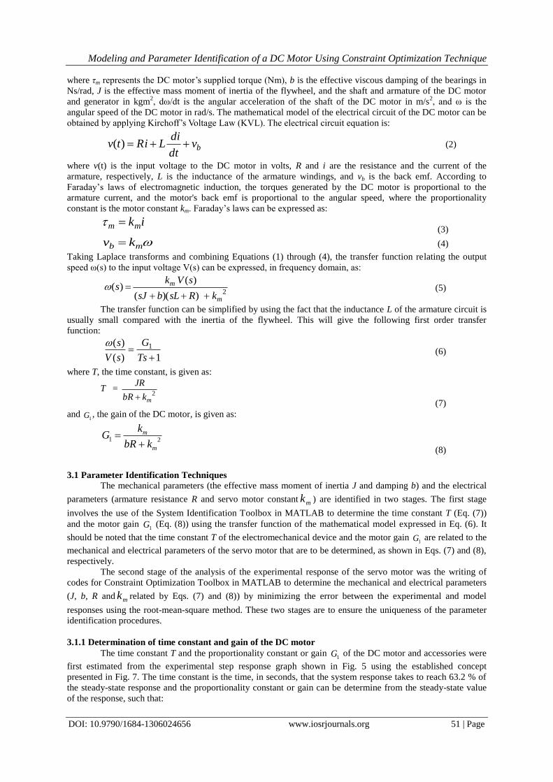
where τm represents the DC motor’s supplied torque (Nm), b is the effective viscous damping of the bearings in
Ns/rad, J is the effective mass moment of inertia of the flywheel, and the shaft and armature of the DC motor
and generator in kgm2, dω/dt is the angular acceleration of the shaft of the DC motor in m/s
2, and ω is the
angular speed of the DC motor in rad/s. The mathematical model of the electrical circuit of the DC motor can be
obtained by applying Kirchoff’s Voltage Law (KVL). The electrical circuit equation is:
(2)
where v(t) is the input voltage to the DC motor in volts, R and i are the resistance and the current of the
armature, respectively, L is the inductance of the armature windings, and vb is the back emf. According to
Faraday’s laws of electromagnetic induction, the torques generated by the DC motor is proportional to the
armature current, and the motor's back emf is proportional to the angular speed, where the proportionality
constant is the motor constant km. Faraday’s laws can be expressed as:
ikmm (3)
mb kv
(4)
Taking Laplace transforms and combining Equations (1) through (4), the transfer function relating the output
speed ω(s) to the input voltage V(s) can be expressed, in frequency domain, as:
2
))((
)()(
m
m
kRsLbsJ
sVks
(5)
The transfer function can be simplified by using the fact that the inductance L of the armature circuit is
usually small compared with the inertia of the flywheel. This will give the following first order transfer
function:
1)(
)( 1
Ts
G
sV
s
(6)
where T, the time constant, is given as:
T = 2
mkbR
JR
(7)
and 1G , the gain of the DC motor, is given as:
21
m
m
kbR
kG
(8)
3.1 Parameter Identification Techniques
The mechanical parameters (the effective mass moment of inertia J and damping b) and the electrical
parameters (armature resistance R and servo motor constant mk ) are identified in two stages. The first stage
involves the use of the System Identification Toolbox in MATLAB to determine the time constant T (Eq. (7))
and the motor gain 1G (Eq. (8)) using the transfer function of the mathematical model expressed in Eq. (6). It
should be noted that the time constant T of the electromechanical device and the motor gain 1G are related to the
mechanical and electrical parameters of the servo motor that are to be determined, as shown in Eqs. (7) and (8),
respectively.
The second stage of the analysis of the experimental response of the servo motor was the writing of
codes for Constraint Optimization Toolbox in MATLAB to determine the mechanical and electrical parameters
(J, b, R and mk related by Eqs. (7) and (8)) by minimizing the error between the experimental and model
responses using the root-mean-square method. These two stages are to ensure the uniqueness of the parameter
identification procedures.
3.1.1 Determination of time constant and gain of the DC motor
The time constant T and the proportionality constant or gain 1G of the DC motor and accessories were
first estimated from the experimental step response graph shown in Fig. 5 using the established concept
presented in Fig. 7. The time constant is the time, in seconds, that the system response takes to reach 63.2 % of
the steady-state response and the proportionality constant or gain can be determine from the steady-state value
of the response, such that:
bvdt
diLiRtv )(
Modeling and Parameter Identification of a DC Motor Using Constraint Optimization Technique
DOI: 10.9790/1684-1306024656 www.iosrjournals.org 52 | Page
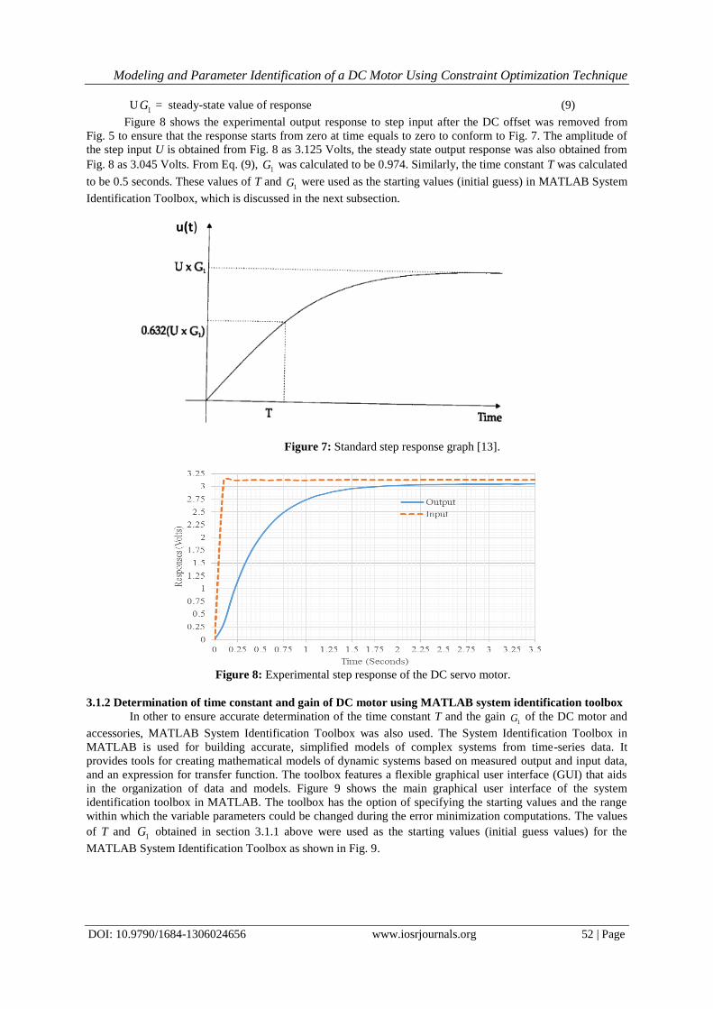
U1G = steady-state value of response (9)
Figure 8 shows the experimental output response to step input after the DC offset was removed from
Fig. 5 to ensure that the response starts from zero at time equals to zero to conform to Fig. 7. The amplitude of
the step input U is obtained from Fig. 8 as 3.125 Volts, the steady state output response was also obtained from
Fig. 8 as 3.045 Volts. From Eq. (9), 1G was calculated to be 0.974. Similarly, the time constant T was calculated
to be 0.5 seconds. These values of T and 1G were used as the starting values (initial guess) in MATLAB System
Identification Toolbox, which is discussed in the next subsection.
Figure 7: Standard step response graph [13].
Figure 8: Experimental step response of the DC servo motor.
3.1.2 Determination of time constant and gain of DC motor using MATLAB system identification toolbox
In other to ensure accurate determination of the time constant T and the gain 1G of the DC motor and
accessories, MATLAB System Identification Toolbox was also used. The System Identification Toolbox in
MATLAB is used for building accurate, simplified models of complex systems from time-series data. It
provides tools for creating mathematical models of dynamic systems based on measured output and input data,
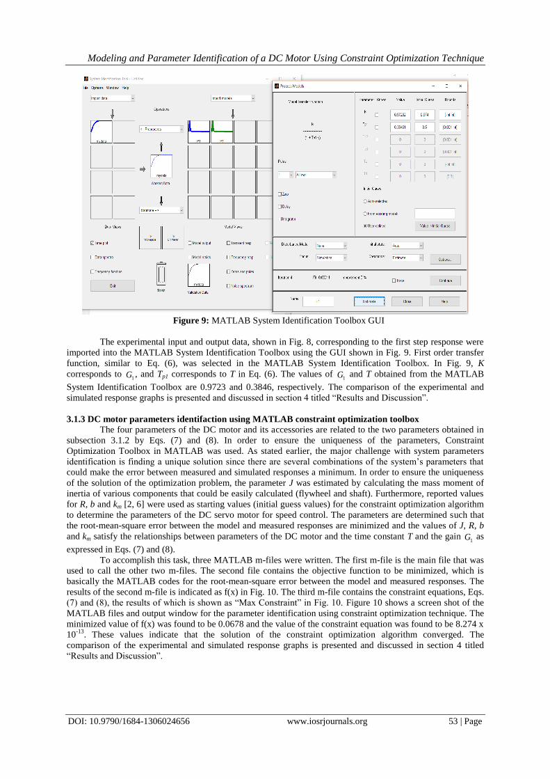
and an expression for transfer function. The toolbox features a flexible graphical user interface (GUI) that aids
in the organization of data and models. Figure 9 shows the main graphical user interface of the system
identification toolbox in MATLAB. The toolbox has the option of specifying the starting values and the range
within which the variable parameters could be changed during the error minimization computations. The values
of T and 1G obtained in section 3.1.1 above were used as the starting values (initial guess values) for the
MATLAB System Identification Toolbox as shown in Fig. 9.
u(t)
Modeling and Parameter Identification of a DC Motor Using Constraint Optimization Technique
DOI: 10.9790/1684-1306024656 www.iosrjournals.org 53 | Page
Figure 9: MATLAB System Identification Toolbox GUI
The experimental input and output data, shown in Fig. 8, corresponding to the first step response were
imported into the MATLAB System Identification Toolbox using the GUI shown in Fig. 9. First order transfer
function, similar to Eq. (6), was selected in the MATLAB System Identification Toolbox. In Fig. 9, K
corresponds to 1G , and Tp1 corresponds to T in Eq. (6). The values of
1G and T obtained from the MATLAB
System Identification Toolbox are 0.9723 and 0.3846, respectively. The comparison of the experimental and
simulated response graphs is presented and discussed in section 4 titled “Results and Discussion”.
3.1.3 DC motor parameters identifaction using MATLAB constraint optimization toolbox
The four parameters of the DC motor and its accessories are related to the two parameters obtained in
subsection 3.1.2 by Eqs. (7) and (8). In order to ensure the uniqueness of the parameters, Constraint
Optimization Toolbox in MATLAB was used. As stated earlier, the major challenge with system parameters
identification is finding a unique solution since there are several combinations of the system’s parameters that
could make the error between measured and simulated responses a minimum. In order to ensure the uniqueness
of the solution of the optimization problem, the parameter J was estimated by calculating the mass moment of
inertia of various components that could be easily calculated (flywheel and shaft). Furthermore, reported values
for R, b and km [2, 6] were used as starting values (initial guess values) for the constraint optimization algorithm
to determine the parameters of the DC servo motor for speed control. The parameters are determined such that
the root-mean-square error between the model and measured responses are minimized and the values of J, R, b
and km satisfy the relationships between parameters of the DC motor and the time constant T and the gain 1G as
expressed in Eqs. (7) and (8).
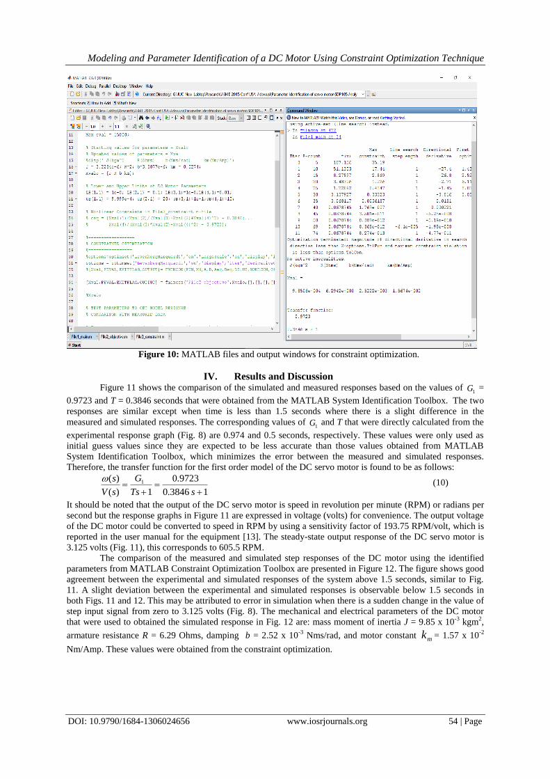
To accomplish this task, three MATLAB m-files were written. The first m-file is the main file that was
used to call the other two m-files. The second file contains the objective function to be minimized, which is
basically the MATLAB codes for the root-mean-square error between the model and measured responses. The
results of the second m-file is indicated as f(x) in Fig. 10. The third m-file contains the constraint equations, Eqs.
(7) and (8), the results of which is shown as “Max Constraint” in Fig. 10. Figure 10 shows a screen shot of the
MATLAB files and output window for the parameter identification using constraint optimization technique. The
minimized value of f(x) was found to be 0.0678 and the value of the constraint equation was found to be 8.274 x
10-13
. These values indicate that the solution of the constraint optimization algorithm converged. The
comparison of the experimental and simulated response graphs is presented and discussed in section 4 titled
“Results and Discussion”.
Modeling and Parameter Identification of a DC Motor Using Constraint Optimization Technique
DOI: 10.9790/1684-1306024656 www.iosrjournals.org 54 | Page
Figure 10: MATLAB files and output windows for constraint optimization.
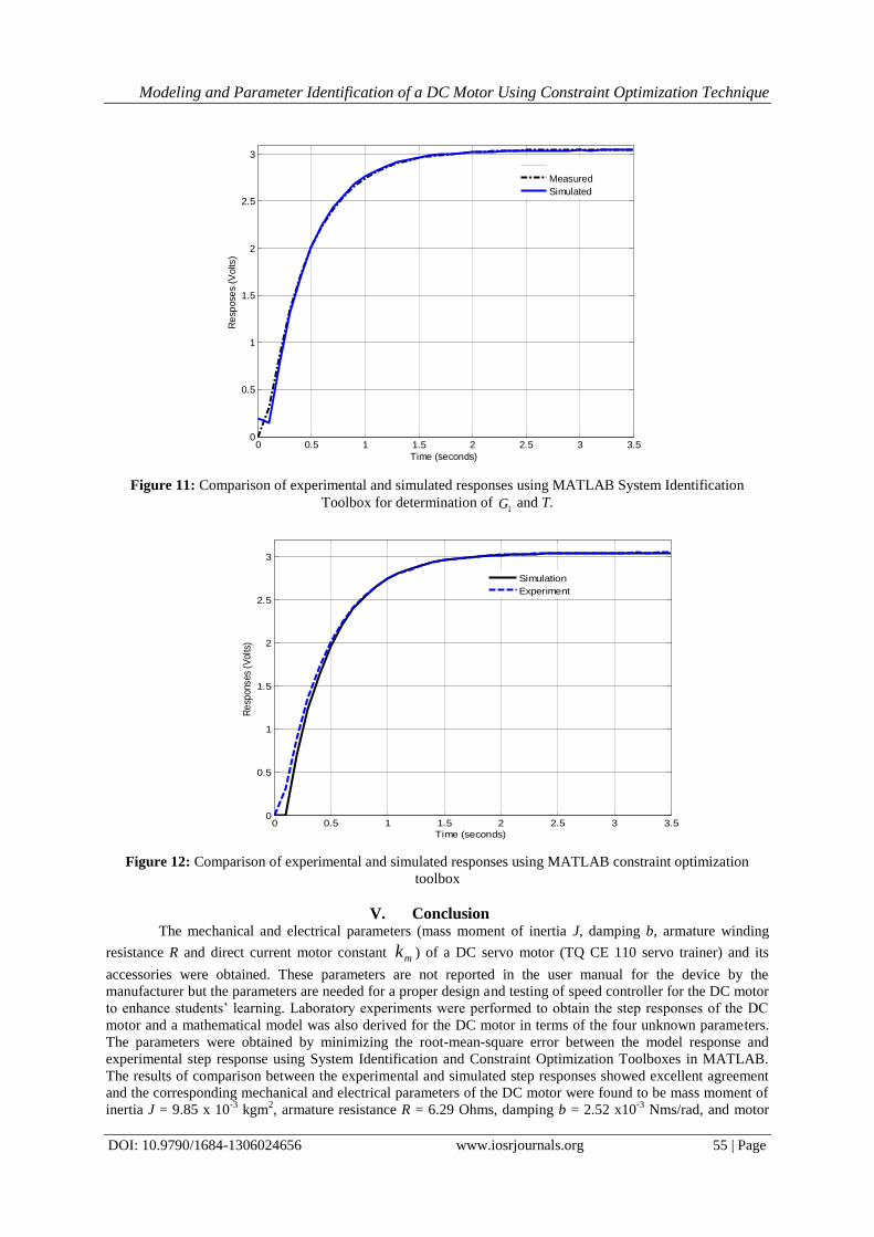
IV. Results and Discussion Figure 11 shows the comparison of the simulated and measured responses based on the values of
1G =
0.9723 and T = 0.3846 seconds that were obtained from the MATLAB System Identification Toolbox. The two
responses are similar except when time is less than 1.5 seconds where there is a slight difference in the
measured and simulated responses. The corresponding values of 1G and T that were directly calculated from the
experimental response graph (Fig. 8) are 0.974 and 0.5 seconds, respectively. These values were only used as
initial guess values since they are expected to be less accurate than those values obtained from MATLAB
System Identification Toolbox, which minimizes the error between the measured and simulated responses.
Therefore, the transfer function for the first order model of the DC servo motor is found to be as follows:
13846.0
9723.0
1)(
)( 1
sTs
G
sV
s (10)
It should be noted that the output of the DC servo motor is speed in revolution per minute (RPM) or radians per
second but the response graphs in Figure 11 are expressed in voltage (volts) for convenience. The output voltage
of the DC motor could be converted to speed in RPM by using a sensitivity factor of 193.75 RPM/volt, which is
reported in the user manual for the equipment [13]. The steady-state output response of the DC servo motor is
3.125 volts (Fig. 11), this corresponds to 605.5 RPM.
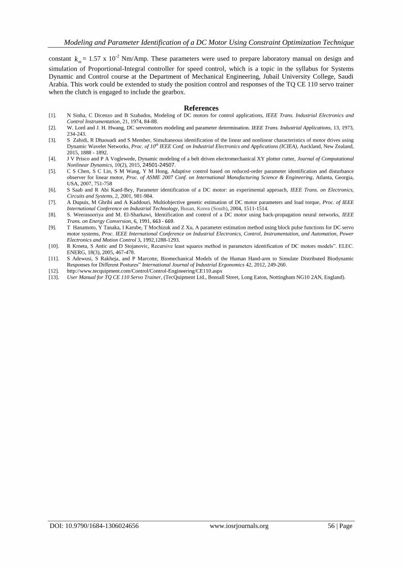
The comparison of the measured and simulated step responses of the DC motor using the identified
parameters from MATLAB Constraint Optimization Toolbox are presented in Figure 12. The figure shows good
agreement between the experimental and simulated responses of the system above 1.5 seconds, similar to Fig.
11. A slight deviation between the experimental and simulated responses is observable below 1.5 seconds in
both Figs. 11 and 12. This may be attributed to error in simulation when there is a sudden change in the value of
step input signal from zero to 3.125 volts (Fig. 8). The mechanical and electrical parameters of the DC motor
that were used to obtained the simulated response in Fig. 12 are: mass moment of inertia J = 9.85 x 10⁻³
kgm2,
armature resistance R = 6.29 Ohms, damping b = 2.52 x 10⁻³
Nms/rad, and motor constant mk = 1.57 x 10⁻²
Nm/Amp. These values were obtained from the constraint optimization.
Modeling and Parameter Identification of a DC Motor Using Constraint Optimization Technique
DOI: 10.9790/1684-1306024656 www.iosrjournals.org 55 | Page
0 0.5 1 1.5 2 2.5 3 3.50
0.5
1
1.5
2
2.5
3
Time (seconds)
Re
spose
s (V
olts
)
Measured
Simulated
Figure 11: Comparison of experimental and simulated responses using MATLAB System Identification
Toolbox for determination of 1G and T.
0 0.5 1 1.5 2 2.5 3 3.50
0.5
1
1.5
2
2.5
3
Time (seconds)
Re
spon
ses
(Vol
ts)
Simulation
Experiment
Figure 12: Comparison of experimental and simulated responses using MATLAB constraint optimization
toolbox
V. Conclusion The mechanical and electrical parameters (mass moment of inertia J, damping b, armature winding
resistance R and direct current motor constant mk ) of a DC servo motor (TQ CE 110 servo trainer) and its
accessories were obtained. These parameters are not reported in the user manual for the device by the
manufacturer but the parameters are needed for a proper design and testing of speed controller for the DC motor
to enhance students’ learning. Laboratory experiments were performed to obtain the step responses of the DC
motor and a mathematical model was also derived for the DC motor in terms of the four unknown parameters.
The parameters were obtained by minimizing the root-mean-square error between the model response and
experimental step response using System Identification and Constraint Optimization Toolboxes in MATLAB.
The results of comparison between the experimental and simulated step responses showed excellent agreement
and the corresponding mechanical and electrical parameters of the DC motor were found to be mass moment of
inertia J = 9.85 x 10⁻³
kgm2, armature resistance R = 6.29 Ohms, damping b = 2.52 x10
-3 Nms/rad, and motor
Modeling and Parameter Identification of a DC Motor Using Constraint Optimization Technique
DOI: 10.9790/1684-1306024656 www.iosrjournals.org 56 | Page
constant mk = 1.57 x 10
-2 Nm/Amp. These parameters were used to prepare laboratory manual on design and
simulation of Proportional-Integral controller for speed control, which is a topic in the syllabus for Systems
Dynamic and Control course at the Department of Mechanical Engineering, Jubail University College, Saudi
Arabia. This work could be extended to study the position control and responses of the TQ CE 110 servo trainer
when the clutch is engaged to include the gearbox.
References [1]. N Sinha, C Dicenzo and B Szabados, Modeling of DC motors for control applications, IEEE Trans. Industrial Electronics and
Control Instrumentation, 21, 1974, 84-88.
[2]. W. Lord and J. H. Hwang, DC servomotors modeling and parameter determination. IEEE Trans. Industrial Applications, 13, 1973,
234-243. [3]. S Zahidi, R Dhaouadi and S Member, Simultaneous identification of the linear and nonlinear characteristics of motor drives using
Dynamic Wavelet Networks, Proc. of 10th IEEE Conf. on Industrial Electronics and Applications (ICIEA), Auckland, New Zealand,
2015, 1888 - 1892. [4]. J V Prisco and P A Voglewede, Dynamic modeling of a belt driven electromechanical XY plotter cutter, Journal of Computational
Nonlinear Dynamics, 10(2), 2015, 24501-24507. [5]. C S Chen, S C Lin, S M Wang, Y M Hong, Adaptive control based on reduced-order parameter identification and disturbance
observer for linear motor, Proc. of ASME 2007 Conf. on International Manufacturing Science & Engineering, Atlanta, Georgia,
USA, 2007, 751-758
[6]. S Saab and R Abi Kaed-Bey, Parameter identification of a DC motor: an experimental approach, IEEE Trans. on Electronics, Circuits and Systems, 2, 2001, 981-984.
[7]. A Dupuis, M Ghribi and A Kaddouri, Multiobjective genetic estimation of DC motor parameters and load torque, Proc. of IEEE
International Conference on Industrial Technology, Busan, Korea (South), 2004, 1511-1514. [8]. S. Weerasooriya and M. El-Sharkawi, Identification and control of a DC motor using back-propagation neural networks, IEEE
Trans. on Energy Conversion, 6, 1991, 663 - 669.
[9]. T Hanamoto, Y Tanaka, I Karube, T Mochizuk and Z Xu, A parameter estimation method using block pulse functions for DC servo
motor systems, Proc. IEEE International Conference on Industrial Electronics, Control, Instrumentation, and Automation, Power
Electronics and Motion Control 3, 1992,1288-1293. [10]. R Krneta, S Antic and D Stojanovic, Recursive least squares method in parameters identification of DC motors models”. ELEC.
ENERG, 18(3), 2005, 467-478.
[11]. S Adewusi, S Rakheja, and P Marcotte, Biomechanical Models of the Human Hand-arm to Simulate Distributed Biodynamic Responses for Different Postures” International Journal of Industrial Ergonomics 42, 2012, 249-260.
[12]. http://www.tecquipment.com/Control/Control-Engineering/CE110.aspx
[13]. User Manual for TQ CE 110 Servo Trainer, (TecQuipment Ltd., Bonsall Street, Long Eaton, Nottingham NG10 2AN, England).