modeling & design of a transformer less active voltage
TRANSCRIPT

International Journal of Electronics Engineering Research.
ISSN 0975-6450 Volume 9, Number 5 (2017) pp. 761-772
© Research India Publications
http://www.ripublication.com
Modeling & Design of A Transformer less Active
Voltage Quality Regulator With A Novel DVR
G. Devadasu #1, Dr. M. Sushama*2
# Department of EEE, CMR College of Engineering & Technology, * Department of EEE, JNTUH University Hyderabad, TS, India.
Abstract
In Restructured power systems, Power quality is one of the major concerns in
the present era. The problem of voltage sags and swells and its major impact
on sensitive loads are well known. To (DVR), which is one of the most
efficient and effective modern custom power devices used in power
distribution networks. A new FLC control algorithm for the DVR is proposed
in this paper to regulate the load terminal voltage during sag, swell in the
voltage at the point solve this problem, custom power devices are used. One of
those devices is the Dynamic Voltage Restorer of common coupling
(PCC).This new control scheme, it is based on fuzzification rules are used for
the generation of reference voltages for a dynamic voltage restorer (DVR).
These voltages, when injected in series with a distribution feeder by a voltage
source inverter (VSI) with PWM control, can regulate the voltage at the load
terminals against any power quality problem in the source side. Wavelets
based analyzes the power circuit of the system in order to come up with
appropriate control limitations and control targets for the compensation
voltage control through the DVR. The control of the DVR is implemented
through derived reference load terminal voltages.
Keywords: sag, swell, Mitigation, fuzzy logic, DVR and VSI
I. INTRODUCTION
There are many different methods to mitigate voltage sags and swells, but the use of a
custom power device is considered to be the most efficient method, e.g. FACTS for
transmission systems which improve the power transfer capabilities and stability
margins. The term custom power pertains to the use of power electronics controller in

762 G. Devadasu and Dr. M. Sushama
a distribution system, especially, to deal with various power quality problems. Custom
power assures customers to get pre-specified quality and reliability of supply. This
pre-specified quality may contain a combination of specifications of the following:
low phase unbalance, no power interruptions, low flicker at the load voltage, and low
harmonic distortion in load voltage, magnitude and duration of over voltages and
under voltages within specified limits, acceptance of fluctuations, and poor factor
loads without significant effect on the terminal voltage. There are different types of
Custom Power devices used in electrical network to improve power quality problems.
Each of the devices has its own benefits and limitations. A few of these reasons are as
follows. The SVC pre-dates the DVR, but the DVR is still preferred because the SVC
has no ability to control active power flow. Another reason include that the DVR has
a higher energy capacity compared to the SMES and UPS devices. Furthermore, the
DVR is smaller in size and cost is less compared to the DSTATCOM and other
custom power devices. Based on these reasons, it is no surprise that the DVR is
widely considered as an effective custom power device in mitigating voltage sags. In
addition to voltage sags and swells compensation, DVR can also add other features
such as harmonics and Power Factor correction. Compared to the other devices, the
DVR is clearly considered to be one of the best economic solutions for its size and
capabilities
II. DYNAMIC VOLTAGE RESTORER (DVR)
DVR is a Custom Power Device used to eliminate supply side voltage disturbances.
DVR also known as Static Series Compensator maintains the load voltage at a desired
magnitude and phase by compensating the voltage sags/swells and voltage unbalances
presented at the point of common coupling.
Fig-1. Schematic diagram of a Dynamic Voltage Restorer

Modeling & Design of A Transformer less Active Voltage Quality Regulator… 763
Basic Configuration of Dynamic Voltage Restorer: The general configuration of the
DVR consists of:
i. Injection/ Booster Transformer: The Injection / Booster transformer is a specially
designed transformer that attempts to limit the coupling of noise and transient energy
from the primary side to the secondary side. Its main tasks are:
It connects the DVR to the distribution network via the HV-windings and
transforms and couples the injected compensating voltages generated by the
voltage source converters to the incoming supply voltage.
In addition, the Injection / Booster transformer serves the purpose of isolating
the load from the system (VSC and control mechanism).
ii. Harmonic Filter: The main task of harmonic filter is to keep the harmonic voltage
content generated by the VSC to the permissible level.
iii. Storage Devices: Batteries, flywheels or SMEs can be used to provide real power
for compensation. Compensation using real power is essential when large voltage sag
occurs.
iv. Voltage Source Converter: A VSC is a power electronic system consists of a
storage device and switching devices which can generate a sinusoidal voltage at any
required frequency, magnitude, and phase angle. In the DVR application, the VSC is
used to temporarily replace the supply voltage or to generate the part of the supply
voltage which is missing. There are four main types of switching devices: Metal
Oxide Semiconductor Field Effect Transistors (MOSFET), Gate Turn-Off thyristors
(GTO), Insulated Gate Bipolar Transistors (IGBT), and Integrated Gate Commutated
Thyristors (IGCT). Each type has its own benefits and drawbacks. The IGCT is a
recent compact device with enhanced performance and reliability that allows building
VSC with very large power ratings. Because of the highly sophisticated converter
design with IGCTs, the DVR can compensate dips which are beyond the capability of
the past DVRs using conventional devices. The purpose of storage devices is to
supply the necessary energy to the VSC via a dc link for the generation of injected
voltages. The different kinds of energy storage devices are Superconductive magnetic
energy storage (SMES), batteries and capacitance.
v. DC Charging Circuit: The DC Charging Circuit has two main tasks.
The first task is to charge the energy source after a sag compensation event.
The second task is to maintain dc link voltage at the nominal dc link voltage

764 G. Devadasu and Dr. M. Sushama
vi. Control and Protection: The control mechanism of the general configuration
typically consists of hardware with programmable logic. All protective functions of
the DVR should be implemented in the software. Differential current protection of the
transformer, or short circuit current on the customer load side are only two examples
of many protection functions possibility.
CARRIER PHASE SHIFTING PULSE WIDTH MODULATION: Carrier phase-
shift sinusoidal pulse width modulation (PS-SPWM) switching scheme is proposed to
operate the switches in the system. Optimum harmonic cancellation is achieved by
phase shifting each carrier by (k-1) π/n. Where k is the kTh inverter, n is the number
of series-connected single phase inverters. n= (L-1)/2
Fig.2 Phase shifted carrier PWM
Fig-2 shows the PSCPWM. In general, a multilevel inverter with m voltage levels
requires (m–1) triangular carriers. In the PSCPWM, all the triangular carriers have the
same frequency and the same peak-to-peak amplitude, but there is a phase shift
between any two adjacent carrier waves, given by φcr=3600/ (m–1). The modulating
signal is usually a three-phase sinusoidal wave with adjustable amplitude and
frequency. The gate signals are generated by comparing the modulating wave with the
carrier waves. It means for five-level inverter four triangular carriers are needed with
a 90° phase displacement between any two adjacent carriers. In this case the phase
displacement of Vcr1 = 0°, Vcr2 = 90°, Vcr1- = 180° and Vcr2- = 270°.
III ADAPTIVE FUZZY DIVIDING FREQUENCY-CONTROL METHOD
The conventional linear feedback controller (PI controller, state feedback control,
etc.) is utilized to improve the dynamic response and/or to increase the stability
margin of the closed loop system. However, these controllers may present a poor
steady-state error for the harmonic reference signal. An adaptive fuzzy dividing

Modeling & Design of A Transformer less Active Voltage Quality Regulator… 765
frequency control method is presented in Fig., which consists of two control units:
1) a generalized integrator control unit and 2) a fuzzy adjustor unit. The generalized
integrator, which can ignore the influence of magnitude and phase, is used for
dividing frequency integral control, while fuzzy arithmetic is used to timely adjust the
PI coefficients.
Fig.3 Configuration of the adaptive fuzzy dividing frequency controller
Since the purpose of the control scheme is to receive a minimum steady-state error,
the harmonic reference signal r is set to zero. First, supply harmonic current is
detected. Then, the expectation control signal of the inverter is revealed by the
adaptive fuzzy dividing frequency controller. The stability of the system is achieved
by a proportional controller, and the perfect dynamic state is received by the
generalized integral controller. The fuzzy adjustor is set to adjust the parameters of
proportional control and generalized integral control. Therefore, the proposed
harmonic current tracking controller can decrease the tracking error of the harmonic
compensation current, and have better dynamic response and robustness.
A. Fuzzy Adjustor
The fuzzy adjustor is used to adjust the parameters of proportional control gain
and integral control gain based on the error e and the change of error
Where are reference values of the fuzzy-generalized integrator PI
controller. In this paper, are calculated offline based on the Ziegler–
Nichols method. In a fuzzy-logic controller, the control action is determined from the
evaluation of a set of simple linguistic rules. The development of the rules requires a
thorough understanding of the process to be controlled, but it does not require a
mathematical model of the system. A block diagram fuzzy-logic adjustor is shown in
Fig.

766 G. Devadasu and Dr. M. Sushama
Fig.4 Block diagram of the fuzzy adjustor unit
In this way, system stability and a fast dynamic response with small overshoot can be
achieved with proper handing of the fuzzy-logic adjustor. Fuzzification converts crisp
data into fuzzy sets, making it comfortable with the fuzzy set representation of the
state variable in the rule. In the fuzzification process, normalization by reforming a
scale transformation is needed at first, which maps the physical values of the state
variable into a normalized universe of discourse.
The error e and change of error are used as numerical variables from the real
system. To convert these numerical variables into linguistic variables, the following
seven fuzzy levels or sets are chosen as [7]: negative big (NB), negative medium
(NM), negative small (NS), zero (ZE), and positive small (PS), positive medium
(PM), and positive big (PB). To ensure the sensitivity and robustness of the controller,
the membership function of the fuzzy sets for and in this
paper are acquired from the ranges of , which are obtained from
project and experience. And the membership functions are shown in Fig.,
respectively.
Fig.5 Membership functions of the fuzzy variable. (a) Membership function of
(b) Membership function of
The core of fuzzy control is the fuzzy control rule, which is obtained mainly from the
intuitive feeling for and experience of the process. The fuzzy control rule design
involves defining rules that relate the input variables to the output model properties.

Modeling & Design of A Transformer less Active Voltage Quality Regulator… 767
For designing the control rule base for tuning , the following important
factors have been taken into account.
1) For large values of , a large is required, and for small values of , a small
is required.
2) For , a large is required, and for a small is required.
3) For large values of , is set to zero, which can avoid control
saturation.
4) For small values of , is effective, and is larger when is smaller,
which is better to decrease the steady-state error. So the tuning rules of and
can be obtained as Tables.
TABLE: ADJUSTING RULE OF THE PARAMETER
TABLE: ADJUSTING RULE OF THE PARAMETER
The inference method employs the MAX-MIN method. The imprecise fuzzy control
action generated from the inference must be transformed to a precise control action in
real applications. The center of gravity method is used to defuzzify the fuzzy variable
into physical domain
768 G. Devadasu and Dr. M. Sushama
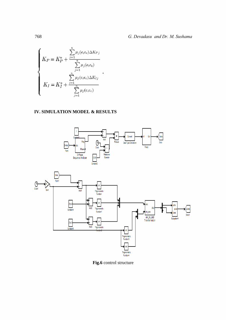
IV. SIMULATION MODEL & RESULTS
Fig.6 control structure

Modeling & Design of A Transformer less Active Voltage Quality Regulator… 769
Fig.7 Simulink diagram of closed loop system for voltage sag and swell
Fig.8 source voltage, voltage sag, compensated output voltage

770 G. Devadasu and Dr. M. Sushama
Fig.9 FFT analysis of voltage sag of DVR
Fig.10 wavelet analysis of sag
Fig.11 source voltage, voltage swell, compensated output voltage

Modeling & Design of A Transformer less Active Voltage Quality Regulator… 771
Fig 12 THD analysis of voltage swell of DVR
Fig. 13 wavelet analysis of swell
V. CONCLUSION
In this paper cascaded H-Bridge Seven level multilevel inverter is implemented as
Dynamic Voltage Restorer to compensate voltage sag, voltage swell and interruption.
Closed loop control of Dynamic Voltage Restorer is designed for better regulation of

772 G. Devadasu and Dr. M. Sushama
the load voltage. Reference signal is generated using PQ theory for closed loop
control with voltage Sag, voltage Swell and interruption are compensated using
Dynamic Voltage Restorer and MATLAB simulations are carried for the above to
maintain load voltage constant.
REFERENCES
[1] G. Yaleinkaya, M.H.J. Bollen, P.A. Crossley, “Characterization of voltage
sags in industrial distribution systems”, IEEE transactions on industry
applications, vol.34, no. 4, July/August, pp. 682-688, 1999.
[2] Haque, M.H., “Compensation of distribution system voltage sag by DVR and
D STATCOM”, Power Tech Proceedings, 2001 IEEE Porto, vol.1, pp.10-13,
Sept. 2001.
[3] Anaya-Lara O, Acha E., “Modeling and analysis of custom power systems by
PSCAD/EMTDC”, IEEE Transactions on Power Delivery, Vol.17, Issue: 1,
Pages:266 – 272, Jan. 2002.
[4] Bollen, M.H.J.,” Voltage sags in three-phase systems” Power Engineering
Review, IEEE, Vol. 21, Issue: 9, pp: 8 - 11, 15, Sept. 2001.
[5] M.Madrigal, E.Acha., “Modelling of Custom Power Equipment Using
Harmonic Domain Techniques”, IEEE 2000.
[6] R.Mienski,R.Pawelek and I.Wasiak., “Shunt Compensation for Power Quality
Improvement Using a STATCOM controller: Modelling and Simulation”,
IEEE Proceedings., Vol.151, No.2. Jan. 2006.
[7] Sasitharan S., Mahesh K. Mishra, Member, IEEE, B.Kalyan Kumar, and
Jayashankar V., member, IEEE, ” Rating and Design Issues of DVR Injection
Transformer”, IEEE Press., New York, 2008.
[8] Math H.J. Bollen, ”Understanding power quality problems: voltage sags and
interruptions”, IEEE Press, New York, 2000.
[9] A.Ghosh and G. Ledwich. ” Power Quality Enhancement Using Custom
Power Devices”, 2002. Kluwer Academic Publishers.
[10] S. Chen, G. Joos, L. Lopes, and W. Guo.” A nonlinear control method of
dynamic voltage restorer” , IEEE 33rd Annual Power Electronics Specialists
Conference. pp. 88- 93.Sept2002.