modeling adaptive multi-agent organizations for naval missions › e-library › conferences ›...
TRANSCRIPT

Modeling Adaptive Multi-Agent Organizations for Naval Missions
MARK HOOGENDOORN1, CATHOLIJN M. JONKER2, MARTIJN C. SCHUT1, AND JAN TREUR1
1Vrije Universiteit Amsterdam, Department of Artificial Intelligence, De Boelelaan 1081a, 1081 HV Amsterdam, The Netherlands
2Radboud University Nijmegen, Nijmegen Institute for Cognition and Information,
Montessorilaan 3, 6525 HR Nijmegen, The Netherlands Abstract. The naval domain is characterized by a dynamic environment. This requires constant adaptation of the organization, choosing between a wide variety of options. The consequences of the different options are difficult to foresee and hence, it is hard to judge which is best. This paper presents automated support for simulation, visualization, and validation of such adaptive multi-agent organisations. Generic simulation properties are specified using a formal modeling approach. Furthermore, results of a realistic case study are presented, and validated by means of properties obtained from naval experts. Finally, a tool is introduced that enables an insightful visualization of the simulation results. Keywords: simulation, formal validation, agents, adaptation, organization, change
1 Introduction
The process of setting up a simulation study involves steps of problem formulation, data collection, model definition, experimental design, running the simulation, output analysis and reporting of results [9]. Throughout this process, intermediate validation steps assure that the simulation model corresponds with the actual system under investigation. The work described in this paper relates to two steps in particular, i.e., model definition and output data analysis, and describe these in more detail.
Model definition concerns setting up a conceptual model of the actual system with respect to project objectives, performance measures, data availability, computer constraints, etcetera. Many tools exist nowadays to support modelers with this activity. For ones specific interest, one may choose from a variety of simulation languages and software packages. These tools provide natural frameworks for model construction. As such, they are based on formal descriptions and include concepts like entities, states, events, time, variables, etcetera.
Agent-based modeling techniques are often used to model and simulate (natural or artificial) agent systems that have to deal with dynamic and uncertain environments. Therefore, an important challenge for the area of agent-based modeling is the notion of adaptivity. Adaptation can take place within a single agent (e.g., an individual learning process), or at the level of the multi-agent organization (e.g, change of roles of agents within the organization). In order to create (multi-)agent-based simulations with adaptive abilities, adaptation
mechanisms have to be incorporated in agent-based simulation models.
Adaptation mechanisms can involve not only quantitative numerical aspects but also qualitative, logical aspects (for example, a role switch between agents within an organization). If formalization is used for an adaptation mechanism, this is often based on mathematical models using differential equations. In contrast, agent-based simulation models traditionally make use of qualitative, logical languages. Most of these languages are appropriate for expressing qualitative relations, but less suitable to work with more complex numerical structures as, for example, in differential equations. Therefore, integrating such mathematical models within the design of (multi-) agent-based simulation models is difficult. To achieve this integration, it is needed to bridge the gap between quantitative approaches and the type of languages typically used in agent-based simulation.
The model definition includes validation of the simulation model: “the process of determining whether a simulation model is an accurate representation of the system, for the particular objectives of the study” [9]. Validation is essential for assuring that the simulation model corresponds with the actual system. Various validation techniques exist, of which one is mentioned in particular. By letting the simulation program generate a run or trace, i.e., the series of states over time of the simulated system (e.g., state variables, statistical counters), it is possible to compare the states with hand calculations to check the validity of the program.
Analysis of output data is in practice still rather undervalued as the simulation process is concerned. Much
Proceedings of the 5th WSEAS Int. Conf. on Artificial Intelligence, Knowledge Engineering and Data Bases, Madrid, Spain, February 15-17, 2006 (pp470-478)

time goes into model development and programming, rather than addressing the generated output results appropriately. A commonly made “error” is that a single run is made of some arbitrary length, supposedly to provide insight into the workings of the actual system. Instead, suitable statistical techniques must be used to design the simulation experiments and analyze the results.
Since the output processes of simulations are almost all nonstationary and autocorrelated [9], classical techniques may not always be applicable. Validation of a model is usually not formally supported. Often validation is done informally, by hand (or eye), based on comparison of a simulation trace with an empirical trace. In addition, sometimes specific (e.g., statistical) techniques are used to support certain aspects of validation; e.g., termination conditions, mean and average estimations (for analysis of single systems), and measuring response differences, ranking, selection (for analysis of multiple systems). However, formal analysis and validation of global dynamic properties describing the system behavior has not received much attention in the simulation modeling literature. Usually in the domain that is modeled, global properties that should hold for the behavior of a simulation model can be identified. As the languages used to specify a simulation model are directed to local properties (the steps between successive states), such global properties cannot be formalized in these languages. To obtain more support, also for validation of a simulation model, it is needed to integrate the modeling of such global properties in a formal manner as well, so that their specification and automated checking on simulation traces also can be supported by the modeling environment. In accordance with the findings mentioned above, this paper introduces an approach for simulation and analysis of adaptive (multi-)agent systems and underlying mechanisms that is integrative in two ways:
(1) It combines in one modeling framework both qualitative, logical and quantitative, numerical aspects. (2) It allows to model dynamics at different aggregation levels, from a more local level (e.g., behaviors of roles within the organization) to a global level (behavior of the multi-agent organization as a whole); moreover, interlevel relations can be specified that express relationships between dynamic properties at different levels
Modeling dynamics at a local level often concerns expressing temporal relationships between pairs of successive states, such as described, for example, by basic steps within an adaptation mechanism. Local level specifications are the basis for the computation steps for a simulation model. From the more global perspective,
more complex relationships over time can be used to model dynamics for adaptive multi-agent organizations: for example, how the system’s behavior is changing during a history of events to which it adapts. Based on the generic approach for simulation as presented above, this paper presents a simulation model for the naval domain. The model mainly concentrates on adaptation of such naval organizations using replanning. The main objective of the research described in this paper is to investigate the suitability of a system involving planning, simulation, visualisation, and validation with respect to automated planning support in naval missions. The longer term aim of this research is to contribute to the development of tools that allow personnel to plan with a confidence and speed that would be impossible otherwise. The remainder of this paper is structured as follows. Section 2 gives some details about the naval domain addressed and how adaptive organisation forms play a role. In Section 3, the modelling methodology that has been used is presented. Section 4 presents a simulation that has been conducted based on local executable properties, and describes a case study that has been investigated. Section 5 presents the plan visualisation tool. Section 6 describes validation results in the form of non-local properties for the case study. Finally, Section 7 concludes and describes future work.
2 Dynamic Aspects in Naval Missions
Within the dynamic naval environment actions of possibly opposing parties, but also possible interference of non-military bystanders might induce a need for change in the organisation to ensure the safety of the mission. Which response to choose in a given situation depends on a variety of factors. Elements such as enemy resources and innocent bystanders have to be taken into consideration and it is hard to predict the consequences of a plan that has been chosen. This paper presents an automated support system for the simulation, visualization, and validation of such processes. Two requirements must be met concerning such support: 1) the support must agree with the current way of working, and 2) guarantees must be given over the resulted planning with respect to given conditions including intended outcome and required resources. The work presented here researches an approach for implementing automated support that meets these two requirements. As the current way of working is concerned, the naval domain knows a large volume of well thought out plans
Proceedings of the 5th WSEAS Int. Conf. on Artificial Intelligence, Knowledge Engineering and Data Bases, Madrid, Spain, February 15-17, 2006 (pp470-478)

that are scheduled for and during a mission (the so-called ‘doctrine’ ). Everyone involved in a mission is familiar with these plans. The performed planning during a mission consists mostly of switching between and carrying out those plans. On the one hand, such planning during a mission may be a matter of executing the plans that were decided upon for the mission; on the other hand, unexpected events may happen that ask for necessary replanning during a mission. Concerning the latter, these situations require appropriate and speedy response. It is essential that in these situations, current circumstances are taken into account, a suitable plan is selected from the doctrine, the situation is dealt with and the mission will continue as originally planned. Adaptation by replanning in the naval domain frequently affects the organisational structure: it actually involves organisational change. For example, in response to an unexpected event, a ship that was originally only an escort of a high-value unit, may have to change its role to an attack unit. Such replanning situations are not rare: organisational changes are frequent and substantial. Another important aspect of naval planning involves spatial information. Feasibility of a plan is partly determined by the nature of the available resources (helicopters, frigates, transporters) and the relative location of those resources. Combining the specific capabilities of the resources with spatial information and timing aspects plays a key role in the planning. Therefore plan visualisation that includes spatial information is necessary for successful implementation of automated planning support in naval applications. In naval missions, it is crucial to consider the planning within the broader context of mission goals, available resources, intended outcomes, etcetera. In this respect,
performed planning before and during a mission must be checked against such kinds of conditions. For example, when an agent is reallocated to another role (e.g., because of prevailing circumstances), it must inform others at the time that it is able to fulfill its role. It is important to recognise that this reallocation does not happen instantaneously (e.g., because a ship may have to sail towards some location to fulfill its new role), and therefore the communication is essential for others to know when the agent can receive orders in its new role. This paper presents a simulation model that includes: a planner (P) for organisational change; a simulator (S) for
those plans that reflects the meta-knowledge (see for example [5]) of the roles involved regarding organisational change; a visualisation tool (VS) for the spatial effects of plan execution that is dedicated to the naval domain; and a validation tool (VL) for the validation of the resulting planning.
The essential virtue of the model is that it recognises the importance of spatial information in naval planning (by means of the visualisation) and it offers an inventive way to check whether given conditions hold while planning (by means of the validation). The model may be used offline for analysis purposes and/or mission planning, as well as during execution of a mission as an automated planning support tool.
3 Modeling Methodology
To facilitate modeling of a multi-agent organization and its dynamics, this section introduces an organizational modeling approach and, in addition, a modeling language that enables specifying the dynamics within an organization (see also [3]). The organizational modeling approach is described in Section 3.1, and Section 3.2 addresses the formal language for expressing dynamics.
3.1 AGR Organization Modeling Approach
For the description of actual multi-agent organizations, the AGR (for agent/group/role) model has been adopted [2]. In that approach, an organization is viewed as a framework for activity and interaction through the definition of groups, roles and their relationships. But, by avoiding an agent-oriented viewpoint, an organization is regarded as a structural relationship between a collection of agents. Thus, an organization can be described solely on the basis of its structure, i.e. by the way groups and roles are arranged to form a whole, without being concerned with the way agents actually behave, and multi-agent systems will be analyzed from the outside, as a set of interaction modes. The specific architecture of agents is purposely not addressed in the organizational model. The three primitive definitions are: • The agents. The model places no constraints on the internal architecture of agents. An agent is only specified as an active communicating entity which plays roles within groups. This agent definition is intentionally general to allow agent designers to adopt the most accurate definition of agent-hood relative to their
Fig. 1. Global overview of the simulation model.
P VS S VL
Proceedings of the 5th WSEAS Int. Conf. on Artificial Intelligence, Knowledge Engineering and Data Bases, Madrid, Spain, February 15-17, 2006 (pp470-478)
application. In this paper, the agents are however assumed to be reflective agents, allowing them to reason about the role they are playing. • Groups are defined as atomic sets of agent aggregation. Each agent is part of one or more groups. In its most basic form, the group is only a way to tag a set of agents. An agent can be a member of n groups at the same time. A major point of these groups is that they can freely overlap. • A role is an abstract representation of an agent function, service or identification within a group. Each agent can handle multiple roles, and each role handled by an agent is local to a group. Roles can also have beliefs due to the assumed reflective capabilities of the agents; they can reason about whether they should have a particular belief given a certain role. Beliefs are seen as an additional requirement on the agents playing that role.
3.2 Modeling Organizational Behavior
In this section a method to express dynamics within an organizational model is addressed. To formally specify dynamic properties at the different aggregation levels that are essential in an organization, an expressive language is needed. To this end the Temporal Trace Language is used as a tool; cf. [7]. For the properties occurring in the paper informal, semi-formal or formal representations are given, based on the Temporal Trace Language (TTL), which is briefly defined as follows. A state ontology is a specification (in order-sorted logic) of a vocabulary. A state for ontology Ont is an assignment of truth-values {true, false} to the set At(Ont) of ground atoms expressed in terms of Ont. The set of all possible states for state ontology Ont is denoted by STATES(Ont). The set of state properties STATPROP(Ont) for state ontology Ont is the set of all propositions over ground atoms from At(Ont). A fixed time frame T is assumed which is linearly ordered. A trace or trajectory γ over a state ontology Ont and time frame T is a mapping γ : T → STATES(Ont), i.e., a sequence of states γt (t ∈ T) in STATES(Ont). The set of all traces over state ontology Ont is denoted by TRACES(Ont). Depending on the application, the time frame T may be dense (e.g., the real numbers), or discrete (e.g., the set of integers or natural numbers or a finite initial segment of the natural numbers), or any other form, as long as it has a linear ordering. The set of dynamic properties DYNPROP(Ont) is the set of temporal statements that can be formulated with respect to traces based on the state ontology Ont in the following manner.
Given a trace γ over state ontology Ont, the input state of some role r within a group g at time point t is denoted by state(γ, t, input(r|g)); analogously state(γ, t, output(r|g)) and state(γ,
t, internal(r|g)) denote the output state and internal state. These states can be related to state properties via the formally defined satisfaction relation |=, comparable to the Holds-predicate in the Situation Calculus: state(γ, t,
output(r|g)) |= p denotes that state property p holds in trace γ at time t in the output state of role r within group g. Based on these statements, dynamic properties can be formulated in a formal manner in a sorted first-order predicate logic with sorts TIME or T for time points, Traces for traces and F for state formulae, using quantifiers over time and the usual first-order logical connectives such as ¬, ∧, ∨, �, ∀, ∃. In trace descriptions, notations such as state(γ, t,
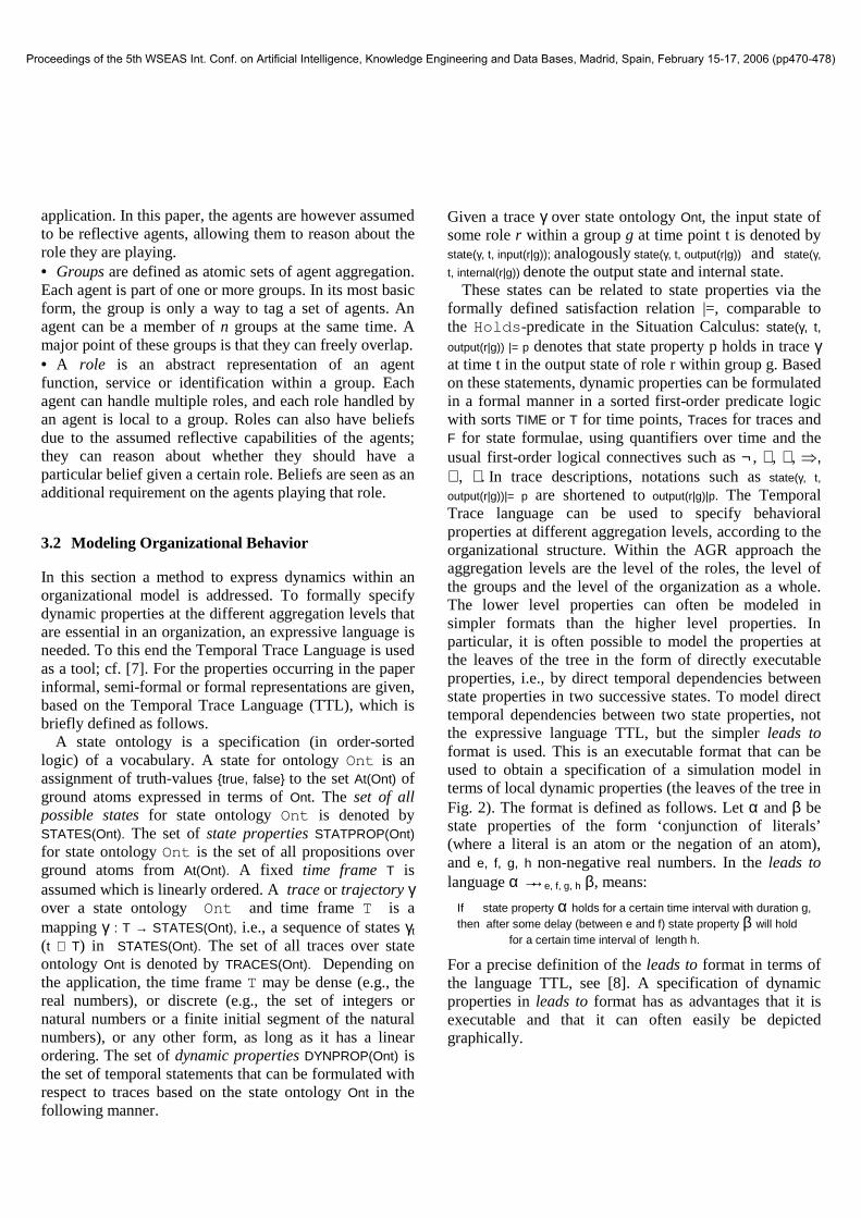
output(r|g))|= p are shortened to output(r|g)|p. The Temporal Trace language can be used to specify behavioral properties at different aggregation levels, according to the organizational structure. Within the AGR approach the aggregation levels are the level of the roles, the level of the groups and the level of the organization as a whole. The lower level properties can often be modeled in simpler formats than the higher level properties. In particular, it is often possible to model the properties at the leaves of the tree in the form of directly executable properties, i.e., by direct temporal dependencies between state properties in two successive states. To model direct temporal dependencies between two state properties, not the expressive language TTL, but the simpler leads to format is used. This is an executable format that can be used to obtain a specification of a simulation model in terms of local dynamic properties (the leaves of the tree in Fig. 2). The format is defined as follows. Let α and β be state properties of the form ‘conjunction of literals’ (where a literal is an atom or the negation of an atom), and e, f, g, h non-negative real numbers. In the leads to language α →→e, f, g, h β, means:
If state property α holds for a certain time interval with duration g, then after some delay (between e and f) state property β will hold for a certain time interval of length h.
For a precise definition of the leads to format in terms of the language TTL, see [8]. A specification of dynamic properties in leads to format has as advantages that it is executable and that it can often easily be depicted graphically.
Proceedings of the 5th WSEAS Int. Conf. on Artificial Intelligence, Knowledge Engineering and Data Bases, Madrid, Spain, February 15-17, 2006 (pp470-478)

4 Local Properties and Simulations
This Section presents the simulator component within the system. First of all, the executable (leads to) properties which specify the simulation model for the simulator are presented in Section 4.1. After that, Section 4.2 addresses the case study that has been investigated, followed by the results of the simulation of the case study.
4.1 Simulation Model Specification
This Section describes generic local properties that constitute the basis for the simulation model. Each of these generic properties can be formed into more scenario specific properties whenever necessary. The generic properties in the framework work are based on goals, plans, beliefs and events. It has to be mentioned that beliefs in this respect are used for storing information about the environment as well as information about oneself. As shown in the scenario below, many plans involve organizational change. This means that the actual organizational structure adapts to occurring events. Thus, in addition to knowing about the environment by observation, it is assumed that the agent (reflectively) knows about its role in the organization and can change to another role if necessary. The formalization is explained in the remainder of this section. Firstly, it is assumed that a goal has been given: internal(r:ROLE|gr:GROUP)|belief(g:GOAL, pos) denotes that role r within group gr holds the belief that g is a goal. Based on this goal, a plan is selected to achieve it: internal(r:ROLE:gr:GROUP)|belief(current_plan(p:PLAN), pos) says that plan p is selected as to achieve goal g. This plan will generate actions as long as no disturbing events occur. If such an event occurs and r is informed, this is denoted by
input(r:ROLE:gr:GROUP)|communication_from_to( r1:ROLE|gr1:GROUP, r:ROLE|gr:GROUP ,inform, e:EVENT)
stating that r1 within group gr1 informs r within group gr about event e. This event causes another goal to become active:
internal(r:ROLE|gr:GROUP)|belief(g1:GOAL, pos) says that g1 is now a goal and a subsequent plan is selected:
internal(r:ROLE|gr:GROUP)|belief(current_plan(p1:PLAN), pos)
This plan may involve organisational change. If this is the case (as it is in the scenarios below), a modeling approach is adopted as developed elsewhere [6]. This involves the existence of a ChangeManager who directs the organizational change. This approach is explained in more detail below. If the plan has been fully executed, this is denoted by
internal(r:ROLE|gr:GROUP)|belief(plan_executed(p:PLAN),pos)
where the parameter might be left out if it is assumed that only one plan can be executed at a time. This causes role r to reflect on other still existing goals and resuming the plans to achieve these goals. If there are no existing goals, a new goal may be generated or given.
Execution of a certain plan that has been selected often consists of organizational change. Therefore, generic simulation rules for these organization structure changes are needed to enable a generic simulation model. The properties shown below are based on the approach presented in [6] which is partially based on the AGR organization modeling approach as presented in Section 3.1. In that approach, organizational change can be performed in a meta-group called ChangeGroup, in which Member roles are present that represent agents within the organization. Each agent in the organization is represented by exactly one Member role within the ChangeGroup. The Member roles have beliefs about the organization and these beliefs are transferred to the roles the agent is currently playing. To initiate the change process as described above, triggers are needed. These are specified in the current plan, and are domain specific. Given this specific information for the particular plan, generic simulation rules fire to simulate the process of informing the members involved and changing their current beliefs on the organization. Some example executable local properties are presented below.
RP(ChangeManager):Communicate Activity [output(ChangeManager|ChangeGroup)|communication_from_to(
ChangeManager|ChangeGroup, all_involved, inform, active(C:CHANGE_GROUP)) &
internal(ChangeManager|ChangeGroup)|belief(involved_in_group(R:ROLE, C:CHANGE_GROUP), pos)]
→→0,0,1,1 input(R:ROLE|ChangeGroup)|communication_from_to(ChangeManager|ChangeGroup, R:ROLE|ChangeGroup, inform, active(C:CHANGE_GROUP)
RP(Member): Believe Change Activity input(R:ROLE|ChangeGroup)|communication_from_to(ChangeManager|ChangeGroup, R:ROLE|ChangeGroup, inform, active(C:CHANGE_GROUP)
→→0,0,1,1 [internal(R:ROLE|ChangeGroup)|belief(active(C:CHANGE_GROUP, pos) & output(R:ROLE|ChangeGroup)|communication_from_to(R:ROLE|ChangeGroup, ChangeManager|ChangeGroup, inform belief(active(C:CHANGE_GROUP), pos))]
Properties such as the examples above cause the ChangeGroup to be activated, knowledge about a new structure to be communicated, and finally belief emerging at the roles that need to have this information. After all of this has been performed, the ChangeGroup is deactivated and the new structure is in place (part of the internals of the roles).
Roles are attributed with reflective knowledge in the approach presented in this paper. This means that roles have beliefs on the expected behavior concerning the role.
Proceedings of the 5th WSEAS Int. Conf. on Artificial Intelligence, Knowledge Engineering and Data Bases, Madrid, Spain, February 15-17, 2006 (pp470-478)

For example, a role has the internal belief that when the role receives an input x he eventually has to output y, formally:
internal(Role|Group)|belief(leadsto(input(Role|Group)|x, output(Role|Group)|y, efgh(0,0,1,1)),pos)
4.2 Simulation Results
This section contains results of simulations using the model presented in Section 3 and the generic properties presented in Section 4.1 which have been formalized in terms of the formal languages presented in Section 3. First of all, the case study is introduced, thereafter some example formal properties which specify the behavior in the situations that occur in the case study are shown. Finally, the simulation trace for the case study is shown.
4.2.1 Case study This section presents a case study that has been obtained from experts of the Royal Netherlands Navy. The scenario contains events that are typical within the naval domain. The scenario that has been studied is called total steam failure. The initial configuration of the fleet is shown in Figure 2. In total there are six frigates, denoted by F1 - F6, each allocated to a certain area within which they reside. Besides the frigates there are also helicopters (H1- H6) flying in a particular zone of the fleet. Finally, there are certain High Value Units (HVU) within the area called ZZ (for Zulu Zulu) that need to be protected. These might for example be ships containing troops, or amphibian landing vehicles. In total there are five ships within ZZ, which is called MainBody throughout this paper.
At a certain point in time the Officer in Tactical Command (OTC) receives an assignment to sail to Peterselie island and chooses a fleet configuration. On the way however, several unexpected events occur. First of all, one of the ships within the MainBody gets a total steam failure, meaning that it has lost all propulsion. On the basis of this event, the OTC has to decide what plan to
apply. A few hours later, a nixie (a torpedo decoy) hit is observed at one of the members of the MainBody, which means that a torpedo was fired in the direction of that ship and implies re-planning as well. Finally, an hour after that, the ship that was suffering from a total steam failure gets back up to speed again.
4.2.2 Case Specific Local Properties This section presents some example properties that have been formalized to enable the simulation of the case study. In case a total steam failure is communicated to the OTC, then the new current plan is to form a screen around this ship. Formally:
RP(OTC): Handle total steam failure input(OTC|Fleet)|communication_from_to(R:ROLE|MainBody1, OTC|Fleet, inform, total_steam_failure) →→0,0,1,1 internal(OTC|Fleet)|belief(current_plan(form_screen_around_ship(
R:ROLE|MainBody1)), pos)
Furthermore, if the plan is indeed set to forming a screen around the ship, then the ship playing the role of FrontLeftProtector within the current screen will be allocated to the role of LeftProtector2 in the newly formed screen. Formally:
RP(OTC): Perform plan to form screen ∀A:AGENT, R:ROLE, G:GROUP [internal(ChangeManager|ChangeGroup)|current_plan(
form_screen_around_ship(R:ROLE|MainBody1)), pos) & internal(ChangeManager|ChangeGroup)|belief(allocated_to(A:AGENT,
FrontLeftProtector1, G:GROUP), pos)] →→0,0,1,1
[internal(ChangeManager|ChangeGroup)|belief(delete(allocated_to( A:AGENT, FrontLeftProtector1, G:GROUP)), pos) &
internal(ChangeManager|ChangeGroup)|belief(add(exists_group(Screen2)), pos) & internal(ChangeManager|ChangeGroup)|belief(add(exists_role(
LeftProtector2)), pos) & internal(ChangeManager|ChangeGroup)|belief(add(allocated_to(
A:AGENT, LeftProtector2, Screen2)), pos)]
4.2.3 Simulation Trace The simulation results of the total steam failure case study are shown in Figure 3. The left side of the Figure shows a selection of the atoms that occur during the simulation. The right side shows a time-line where a black box indicates when an atom is true and a grey box when an atoms is false. This subset of the trace focuses on the OTC within the fleet, as he is the commander, he is the most interesting role to show. More specifically, the trace shows that during all time points the current mission is to sail to Peterselie island:
internal(OTC|Fleet)|belief(current_mission(sail_to_peterselie_island), pos)
After the mission has been received, the initial organization is set-up according to the approach presented in Section 3.1. After the organization change process has ended the OTC has beliefs on the structure and allocations within the fleet, such as:
Fig. 2. Initial Fleet configuration
Proceedings of the 5th WSEAS Int. Conf. on Artificial Intelligence, Knowledge Engineering and Data Bases, Madrid, Spain, February 15-17, 2006 (pp470-478)

internal(OTC|Fleet)|belief(exists_role(FrontLeftProtector1), pos) internal(OTC|Fleet)|belief(allocated_to(F1,LeftProtector1, Screen1), pos)
Suddenly, the OTC receives a communication from the role BodyMember1 within the MainBody1 group stating that the role has a total steam failure:
input(OTC|Fleet)|communication_from_to(BodyMember1|MainBody1, OTC|Fleet, inform, total_steam_failure)
Based on this communication, the OTC decides to form a screen around the ship, which means that the current fleet configuration as presented in the case-study changes drastically. As organizational change comes into play, the ChangeManager becomes active again, who forms a new group Screen2 (denoting the additional screen) and an additional main body (MainBody2). Several agents that were at first allocated to the screen around MainBody1 are now re-allocated to roles in Screen2 around the newly formed MainBody2. To determine which agents to re-allocate, specific properties are present in the simulator that define a preference for which agent to take. Once the agents are in their new positions, they communicate this in their new role:
input(OTC|Fleet)|communication_from_to(LeftProtector2|Screen2, OTC|Fleet, inform, able_to_fulfill_role)
After these communications have been received, the OTC believes that the plan is executed successfully. A few time-points later however, the OTC observes that the distance between MainBody1 and MainBody2 is almost out of the bounds that have been set. As a response, the OTC commands the member of MainBody1 to slow down. Just after that command has been executed, an unexpected event occurs: A nixie hit is observed. This trigger causes the OTC to choose a new plan to be executed, because there is a severe danger of being attacked. The plan chosen is to form a search and attack unit, which will try to pinpoint the ship that fired the torpedo. Therefore, another organizational change is observed, creating the roles for the search and attack unit and re-allocating agents to these roles. In the trace this organization change involves a dynamic property being communicated, stating what the search and attack unit should perform: internal((SAUC|SAU))|belief(leadsto(
internal(('OTC'|'Fleet'))|belief(current_mission(sail_to_peterselie_island), pos)internal(('OTC'|'Fleet'))|belief(exists_role('FrontLeftProtector1'), pos)
internal(('OTC'|'Fleet'))|belief(exists_group('Screen1'), pos)internal(('OTC'|'Fleet'))|belief(role_belongs_to_group('FrontLeftProtector1', 'Screen1'), pos)
internal(('OTC'|'Fleet'))|belief(allocated_to('F2', 'FrontLeftProtector1', 'Screen1'), pos)input(('OTC'|'Fleet'))|observation_result(speed('MainBody1', normal), pos)
internal(('OTC'|'Fleet'))|belief(allocated_to('JDW', 'BodyMember1', 'MainBody1'), pos)input(('OTC'|'Fleet'))|communication_from_to(('BodyMember1'|'MainBody1'), ('OTC'|'Fleet'), inform, total_steam_failure)
internal(('OTC'|'Fleet'))|belief(current_plan(form_screen_around_ship(('BodyMember1'|'MainBody1'))), pos)input(('OTC'|'Fleet'))|observation_result(speed('MainBody2', dead), pos)
internal(('OTC'|'Fleet'))|belief(allocated_to('F2', 'LeftProtector2', 'Screen2'), pos)internal(('OTC'|'Fleet'))|belief(allocated_to('JDW', 'Body2Member1', 'MainBody2'), pos)
internal(('OTC'|'Fleet'))|belief(allocated_to('F2', 'ASWC2', 'Screen2'), pos)internal(('OTC'|'Fleet'))|belief(allocated_to('F2', 'ScreenCommander2', 'Screen2'), pos)
internal(('OTC'|'Fleet'))|belief(plan_executed, pos)input(('OTC'|'Fleet'))|communication_from_to(('LeftProtector2'|'Screen2'), ('OTC'|'Fleet'), inform, able_to_fulfill_role)
input(('OTC'|'Fleet'))|observation_result(almost_outside_bounds('MainBody1', 'MainBody2'), pos)output(('OTC'|'Fleet'))|communication_from_to(('OTC'|'Fleet'), ('BodyMember2'|'MainBody1'), inform, slow_down)
input(('OTC'|'Fleet'))|communication_from_to(('BodyMember2'|'MainBody1'), ('OTC'|'Fleet'), inform, slowed_down)input(('OTC'|'Fleet'))|observation_result(speed('MainBody1', slow), pos)
input(('OTC'|'Fleet'))|observation_result(nixie_hit('BodyMember2', 'MainBody1'), pos)internal(('OTC'|'Fleet'))|belief(current_plan(form_search_and_attack_unit(('BodyMember2'|'MainBody1'))), pos)
internal(('OTC'|'Fleet'))|belief(allocated_to('H1', 'SAUC', 'SAU'), pos)output(('OTC'|'Fleet'))|communication_from_to(('OTC'|'Fleet'), ('BodyMember2'|'MainBody1'), inform, accelerate_to_max_speed)input(('OTC'|'Fleet'))|communication_from_to(('BodyMember2'|'MainBody1'), ('OTC'|'Fleet'), inform, accelerated_to_max_speed)
input(('OTC'|'Fleet'))|observation_result(speed('MainBody1', fast), pos)output(('OTC'|'Fleet'))|communication_from_to(('OTC'|'Fleet'), ('BodyMember2'|'MainBody1'), inform, slow_down_to_regular_speed)
input(('OTC'|'Fleet'))|communication_from_to(('BodyMember2'|'MainBody1'), ('OTC'|'Fleet'), inform, slowed_down_to_regular_speed)input(('OTC'|'Fleet'))|communication_from_to(('Body2Member1'|'MainBody2'), ('OTC'|'Fleet'), inform, steam)
internal(('OTC'|'Fleet'))|belief(current_plan(restore_old_screen_configuration), pos)output(('OTC'|'Fleet'))|communication_from_to(('OTC'|'Fleet'), ('Body2Member1'|'MainBody2'), inform, accelerate_to_max_speed)input(('OTC'|'Fleet'))|communication_from_to(('Body2Member1'|'MainBody2'), ('OTC'|'Fleet'), inform, accelerated_to_max_speed)
input(('OTC'|'Fleet'))|observation_result(speed('MainBody2', fast), pos)input(('OTC'|'Fleet'))|communication_from_to(('Body2Member1'|'MainBody2'), ('OTC'|'Fleet'), inform, arrived_at_mainbody1)
input(('OTC'|'Fleet'))|communication_from_to(('BodyMember1'|'MainBody1'), ('OTC'|'Fleet'), inform, able_to_fulfill_role)time 0 50 100 150 200 250 300 350 400 450
Fig. 3. Simulation result of the Total Steam Failure scenario
Proceedings of the 5th WSEAS Int. Conf. on Artificial Intelligence, Knowledge Engineering and Data Bases, Madrid, Spain, February 15-17, 2006 (pp470-478)

internal((SAUC|SAU))|belief(able_to_fulfill_role, pos), output((SAUC|SAU))|communication_from_to((SAUC|SAU), (OTC|Fleet), inform, started_plan_spencer), efgh(0, 0, 1, 1)), pos)
This states that once the role is fulfilled, the role will execute plan spencer and inform the OTC about this. Due to the reflective capabilities of the agent, they are able to reason about these dynamic properties and adopt them. After the OTC has observed that plan spencer is indeed being executed, he orders the remainder of MainBody1 to accelerate to maximum speed. After a while, the search and attack unit has fully executed plan spencer, resulting in the OTC deleting the group and re-allocating the agents to their old role. The final event that changes the organization is the communication from MainBody2 that it has steam again which is a trigger for a new plan, to restore the old fleet configuration. This is established by having MainBody2 and Screen2 accelerate to maximum speed and when it arrives at the MainBody1 allocated all the ships and helicopters to their old position again.
5 Visualization
For the simulator a visualization tool has also been developed. Figure 4 shows a screenshot of the tool. On the left side of the figure the fleet is shown in a visual manner as previously shown in Figure 2 whereas on the right side the trace (of which parts were explained already in Section 4.2), that acts as a basis for the visualization, is shown. A bar in the trace shows the accompanying time-point for which this visualization holds. For Navy domain experts such a visualization tool is easily interpretable whereas a trace as shown on the right side of Figure 4 is hard to interpret especially due to the fact that one needs
to be familiar with such kind of formalisms.
6 Non-Local Properties and Validation
When a formalized trace has been obtained either by a formalization of an empirical trace or by means of simulation it is useful to verify certain essential properties in the trace. Below the properties that have been checked against the traces presented in Section 4 are shown. The properties are independent from the specific scenario and should hold for every trace. The properties are formalized using the Temporal Trace Language as described in Section 3.
P1: Reflective Behavior This property states that in case a role has a belief about an executable property that should be used when the role is being performed, the role should actually show this behavior. Formally:
∀γ:TRACES, t:TIME, [∃A:ANTECEDENT, C:CONSEQUENT, R:ROLE, G:GROUP
state(γ, t, internal(R|G)) |= belief(leadsto(A, C, efgh(_,_,_,_)), pos) � ∀t2 � t [state(γ, t2) |= A � ∃t3 � t2 state(γ, t3) |= C ]]
This property is indeed satisfied for the presented traces.
P2: Ship always allocated to a role The fact that a ship should always be allocated to a role (after the initial fleet setup) is specified using this property. In formal: ∀γ:TRACES, t:TIME > 20, A:AGENT [∃R:ROLE, G:GROUP state(γ, t, internal(OTC|Fleet)) |= belief(allocated_to(A, R, G), pos)]
This property is also satisfied for the given traces.
P3: Communication that an agent is able to fulfill its role This property expresses that when an agent is re-allocated to another role, it should always communicate when it is able to fulfill the role. There can be a time-delay between the re-allocation because the ship might have to sail to a particular place to execute the newly assigned role. Formally the property can be specified in the following way
∀γ:TRACES, t:TIME > 20, A:AGENT, R:ROLE, G:GROUP [∃R2:ROLE state(γ, t, input(ChangeManager|ChangeGroup)) |=
communication_from_to(R2|ChangeGroup, ChangeManager|ChangeGroup, inform, belief(add(allocated_to(A, R, G)), pos))
� [∃t2:TIME � t1 state(γ, t2, output(R|G)) |= communication_from_to(R|G, OTC|Fleet, inform, able_to_fulfil_fole)]]
This property is satisfied as well for the given traces.
P4: Determine a plan to handle exceptions When an exception occurs the OTC within the fleet always has a belief about a current plan that handles the exception:
Fig. 4. Screenshot of the visualization tool
Proceedings of the 5th WSEAS Int. Conf. on Artificial Intelligence, Knowledge Engineering and Data Bases, Madrid, Spain, February 15-17, 2006 (pp470-478)
∀γ:TRACES, t:TIME [∃E:EXCEPTION state(γ, t, input(OTC|Fleet)) |= E � ∃t2:TIME � t, P:PLAN [state(γ, t2, internal(OTC|Fleet)) |= belief(current_plan(P), pos)]]
This property is satisfied for the trace shown in Section 4.
7 Conclusion
This paper introduces an integrative modeling approach for simulation and analysis of adaptive behavior of multi-agent organizations. The approach is integrative in two ways. First, it combines both qualitative, logical and quantitative, numerical aspects in one modeling framework. Second, it allows to model dynamics at different aggregation levels from local to global levels.
The organizational processes during naval missions have been formalized by identifying executable local dynamic properties for the basic dynamics. On the basis of these local properties simulations have been made. Moreover, dynamic properties describing the behavior at a global level have been identified. These properties have been checked automatically on the simulation traces. To this end a system has been introduced that consists of four components: (1) A planning component; (2) a simulation engine; (3) a visualization tool, and (4) a component which enables formal validation. The planning component has been equiped with typical plans for the naval domain from the so called ‘doctrine’ . The simulation engine has as a basis an organizational model which is specified by means of dynamics in the form of formal executable properties. Organizational change and change of plans are visualized in an understandable manner for naval experts by means of the visualization tool. Finally, the validation component enables formal validation of traces.
The approach taken in this paper has a number of advantages over other approaches. When comparing with planning achitictures such as [4] and [1], the approach presented in this paper provides validation functionalities for the simulation results, which is not the case in the other architectures. The models of these architectures can be formally proven to be correct, however for the complex naval domain it might be too diffult to prove such a thing. Furthemore the approach in this paper also has the ability to validate and visualize empirical traces who can for example be obtained from logbooks. These advantages could be used to monitor a current mission, and constantly check whether the properties that should hold for the mission are satisfied. In case a property is not satisfied, a warning could for example be given.
Other simulation engines have been developed specifically for the naval domain, such as for example presented in [10]. For a matter of validation of the model however, navy experts were asked what they considered the optimal solution. In the approach used in this paper, this process is automated due to the formal specification of properties provided to us by naval domain experts.
Acknowledgements
CAMS-Force Vision, the software development department associated with the Royal Netherlands Navy, has provided funding and domain knowledge to enable the scenarios and simulations presented in this paper. The authors especially want to thank Jaap de Boer (CAMS-ForceVision) for his expert knowledge.
References
1. d'Inverno, M., Luck, M. Georgeff, M., Kinny, D. and Wooldridge, M., The dMARS Architechure: A Specification of the Distributed Multi-Agent Reasoning System. Journal of Autonomous Agents and Multi-Agent Systems, 9(1-2):5-53, 2004.
2. Ferber, J. and Gutknecht, O., A meta-model for the analysis and design of organisations in multi-agent systems. In: Proceedings of the Third International Conference on Multi-Agent Systems (ICMAS’98), IEEE Computer Society Press, pp. 128-135.
3. Ferber, J., Gutknecht, O., Jonker, C.M., Müller, J.P., and Treur, J., Organization Models and Behavioural Requirements Specification for Multi-Agent Systems. In: Y. Demazeau, F. Garijo (eds.), Multi-Agent System Organisations. Proc. of the 10th European Workshop on Modelling Autonomous Agents in a Multi-Agent World, MAAMAW'01.
4. Georgeff, M. P., and Ingrand, F. F., Decision-making in an embedded reasoning system. In Proceedings of the Eleventh International Joint Conference on Artificial Intelligence (IJCAI-89), pages 972-978, Detroit, MI, 1989.
5. Goodwin, R., Meta-Level Control for Decision-Theoretic Planners. PhD thesis, School of Computer Science, Carnegie Mellon University, Pittsburgh, PA, 1996.
6. Hoogendoorn, M., Jonker, C.M., Schut, M.C., and Treur, J., Modelling the Organisation of Organisational Change. In: Proc. of the Sixth International Workshop on Agent-Oriented Information Systems, AOIS'04.
7. Jonker, C.M., Treur, J. Compositional verification of multi-agent systems: a formal analysis of pro-activeness and reactiveness. International. Journal of Cooperative Information Systems, vol. 11, 2002, pp. 51-92.
8. Jonker, C.M., Treur, J., and Wijngaards, W.C.A., A Temporal Modelling Environment for Internally Grounded Beliefs, Desires and Intentions. Cognitive Systems Research Journal, vol. 4, 2003, pp. 191-210.
9. Law A.M. and Kelton D.W., Simulation, Modeling and Analysis. McGraw Hill, 2000. Third edition.
10. Sokolowski, J., Enhanced Military Decision Modeling Using a MultiAgent System Approach, In Proceedings of the Twelfth Conference on Behavior Representation in Modeling and Simulation, Scottsdale, AZ., May 12-15, 2003, pp. 179-186
Proceedings of the 5th WSEAS Int. Conf. on Artificial Intelligence, Knowledge Engineering and Data Bases, Madrid, Spain, February 15-17, 2006 (pp470-478)