modeling ad-hoc medical imaging workflows with bpel4ws · modeling ad-hoc medical imaging workflows...
TRANSCRIPT

Modeling ad-hoc medical imaging workflows with BPEL4WS
Rainer Anzböck1, Schahram Dustdar2, and Masoud Gholami3
1, 3 D.A.T.A. Corporation, Invalidenstrasse 5-7/10, 1030 Wien, Austria
{ar|gm}@data.at 2 Distributed Systems Group, Vienna University of Technology
Argentinierstrasse 8/184-1, 1040 Wien, Austria [email protected]
Abstract. Web services workflows are increasingly gaining attention. With the advent of emerging standards such as the Business Process Execution Language for Web Services (BPEL4WS) medical organizations are investigating the op-tions for modeling ad-hoc workflows. In this paper we analyze a highly relevant ad-hoc workflow in the medical imaging domain: the second opinion workflow. Since this workflow, by its nature, involves other (increasingly ubiquitous) in-formation systems (e.g. imaging equipment), it may serve as a test candidate for the applicability and suitability of BPEL4WS in the medical imaging domain. The workflow model covers implementation relevant aspects of the DICOM and HL7 protocol while maintaining an abstract domain model. The paper pro-vides a separation of a basic workflow and the extended ad-hoc workflow. Fur-ther it abstracts the communication protocols by implementing sub-workflows for the service interfaces. The paper also analyzes mapping problems between the workflow and the communication layer and points out further ad-hoc work-flow specifications for the medical imaging domain.
1 Introduction
With recent work in the field of ad-hoc workflows it is possible to define more flexible business models than in traditional workflows based on the Workflow refer-ence model (WFMC) [1]. With the standardization of the Business Process Execution Language (BPEL4WS, short BPEL) [2] a new implementation method for Web ser-vice based scenarios is available. The medical imaging domain is currently in a dy-namic evolution to digitally connected networks. Standardization in the field of medi-cal imaging has been covered by the HL7 [3] and DICOM [4] standards. A related standardization process for health informatics is enforced by the European Union with the CEN/TC 251 work program [5] which is out of the scope of this paper but is rec-ognized as an important research area.
The goal of this paper is to analyze a highly relevant ad-hoc workflow [6] in the medical imaging domain: the second opinion workflow. Since this workflow, by its nature, involves other (increasingly ubiquitous) information systems (e.g. imaging

equipment), it may serve as a test case for the applicability and suitability of BPEL in the medical imaging domain. The workflow model covers implementation relevant aspects of the DICOM and HL7 protocol while maintaining an abstract domain model.
The contribution of this paper is as follows: First it introduces current research is-sues in loosely coupled ad-hoc workflow models and defines a formal basis for simple workflow pattern. Secondly, it provides a separation of a basic workflow and the ex-tended ad-hoc (second opinion) workflow. In the next step it abstracts the communica-tion protocols by implementing sub-workflows for the service interfaces. Furthermore we analyze mapping problems between the workflow and the communication layer and point out the relationships to ad-hoc workflow specifications for the medical imaging domain. Finally we provide a WSDL [7] and BPEL specification of the second opin-ion workflow.
To summarize, our paper (i) analyzes the second opinion ad-hoc workflow in the medical imaging domain and analyzes the requirements for modeling such workflows, (ii) suggests flexible communication semantics not covered in recent work of work-flow management and Web services technology and (iii) investigates whether the current BPEL definition is applicable and suitable for the medical imaging domain.
The paper is structured as follows. Section 2 introduces ad-hoc workflows and pro-vides definitions of workflow patterns. Section 3 provides an introduction to. Section 4 introduces the ad-hoc workflow and its ad-hoc mechanism required for modeling. Section 5 discusses the relationship between the workflow model and the implementa-tion protocols and suggests a mapping terminology. It extends the discussion to cur-rent standardization processes. Section 6 concludes the results and provides informa-tion about related work.
2 Medical Imaging
In this section a brief introduction to the medical imaging domain is provided. A more detailed discussion can be found in [8], [9], [10], [11] and [12]. Next, two sam-ple workflows are introduced to be inspected further.
2.1 HIS, RIS and PACS
Three systems, the HIS (Hospital Information System) [13], the RIS (Radiology Information System) [12] and the PACS (Picture Achieving and Communication sys-tem) [10] are the backbone of current information systems in the hospital and medical imaging environment, comparable to ERP (Enterprise Resource Planning) and SCM (Supply Chain Management) systems. The HIS is an enterprise-wide system mostly used for administrative tasks like patient and visit management, bed reservations, patient referrals, operation planning, other scheduling tasks and billing management. The RIS is a patient- management system required for all organizational tasks of a medical imaging facility (whether in- or outside a hospital) like examination schedul-ing, patient registration, worklist generation, examination control, report generation (using digital dictation equipment and speech recognition) report transcription and

transfer and billing management for insurance companies. As can be seen, both sys-tems have overlapping tasks to fulfill, own on an enterprise the other on an office level. The second main software system in medical imaging is called PACS and is responsible for all image management tasks. It transfers patient data to examination facilities (modalities), announces finished procedures and stores, prints, burns CDs, archives or transfers the generated image data.
2.2 DICOM and HL7
The most relevant protocol standards for these applications are HL7 for the RIS and DICOM for the PACS. PACS and RIS both implement a workflow model and cover implementations of the standard. Both systems have to be tightly integrated to perform tasks efficiently. The DICOM 3 standard covers Client/Server communica-tions used to exchange Patient and Examination information. The standard covers objects like patients, visits, medical procedures, images, films, printers, and examina-tion modalities. Additionally, notifications, data query, and exchange services based on these objects are defined. The HL7 standard is used for data exchange between different healthcare providers and is more suited for non-radiological institutions. Some functionality overlaps with DICOM for example the scheduling process and the patient and result management. Other functionality such as the exchange of image data is not part of HL7. More detailed information on DICOM can be found in [14] and [15].
2.3 Medical Imaging Workflow
Figure 1 provides an overview on the main parts of the overall medical imaging workflow in UML [16], [17] Use-Case notation.

Fig. 1. Medical imaging use-cases follow medical and administrative tasks. The RIS supports nearly all of these tasks with proprietary implementations and through the DICOM and HL7 standards.
It consists of seven different tasks regarding all aspects of a medical imaging facil-
ity. These interactions should now be modeled in ad-hoc workflows. A more detailed description can be found in [11], [12] and [13]. In this paper we focus on the patient registration and second opinion tasks to investigate further. The tasks should be mod-eled in BPEL and correspond to the responsibilities of the DICOM and HL7 standard as introduced above. The next section also relates the sample workflows to these communication protocols. In Figure 2 a closer look to the external environment is taken. It shows the relationship between two medical imaging facilities and a Hospital.
Fig. 2. In the HIS/RIS and RIS/RIS environment several Use-cases are performed in a loosely coupled manner. The implementation use standard protocols, where HL7 is more HIS related and DICOM is more inter-RIS related. The many-to-many relationship results from multiple facilities communicating with each other depending on the Use-case.
The Radiology Information System (RIS) and Hospital Information System (HIS)
are the major applications maintained in a Hospital and medical imaging facility envi-ronment. The two tasks are independent from each other and some facilities share both or none of them. Further the communication semantics implemented for the tasks can be different depending on the functionality of the HIS and RIS system (ex. DICOM

might be supported by a node or not). Both systems have to provide an interface based on the BPEL workflow definition. To create a workflow model using BPEL it is nec-essary to define separate services for patient registration and second opinion as shown in Figure 3 and 4.
Fig. 3. In the patient registration workflow the HIS normally performs the service provider role and the RIS the service user role (this might change in special situations). Both applica-tions implement a scheduling or registration module with a HL7 interface.
For the patient registration normally the HIS application is the user and the RIS is
the provider, rarely the reverse is the case. Additionally the Use-case has some spe-cific scenarios where pre-registrations in case of emergencies are required. This paper concentrates on the second opinion Use-case and has to leave this discussion to further research.
Fig. 4. In the patient registration workflow the HIS normally performs the service provider role and the RIS the service user role (this might change in special situations). Both applica-tions implement a scheduling or registration module with a HL7 interface.
For the second opinion the relationship is rather symmetric, therefore both partners
play the roles of provider and user of the service. Further DICOM and HL7 are re-

quired for an efficient second opinion workflow. Because of its usefulness in quality management, the more homogenous environment and the precise requirements defini-tion we choose this Use-case to investigate further. The next section provides a de-tailed description of an ad-hoc workflow model for this service.
3 AD-HOC Workflows
In this section a brief introduction to ad-hoc workflows is provided. First we intro-duce the loosely coupled workflow model and current research topics for ad-hoc workflows. Then we provide a description and formal definition of common workflow pattern together with samples of our second opinion Use-case. This frame supports the definition of a workflow model in the next chapter.
3.1 Loosely coupled workflow model
Figure 5 shows the loosely coupled workflow model, a model where each participant implements its own workflow. The model has been introduced and is described in more detail in [18] and [19].
Fig. 5. In the loosely coupled workflow model each participant implements its own workflow and maintains an infrastructure, like workflow engine, etc. At defined synchronization points work items can be exchanged to constitute an inter-organizational workflow.
Additionally the workflows are connected on certain points of interaction. In an ad-hoc environment the participants should be selected dynamically leading to a more flexible way of interaction. To allow for a dynamic assignment, the process definition has to be stored as a template as introduced in [18] and evaluated in [20]. The tem-plate defines the process states, activities and roles of the workflow. When the process is instantiated a specific participant is chosen for a role in the workflow. For example the radiologist generating the report for a specific case is dynamically selected based on availability, expertise on the case and other modeled attributes of the activity. All attributes, connection parameters, etc. should be stored as metadata in the messages of a service specification.
Another advantage over traditional workflow models is the extension of models through escalations [20]. An escalation defines additional activities and is inserted into the process model at certain escalation points. It can be triggered by a participant that is defined as an expert with respect to the process definition (ex. a radiologist for
requesting a second opinion on a case). Escalations extend the running process in-stance and participants filling the roles that perform the activities are again dynami-cally assigned.
These extensions are also based on the WFMC reference model and extend the model with dynamic aspects. In [20] it is concluded that current workflow systems don’t support dynamic assignment of participants or extensions of workflow instances. Therefore a complete new framework has been designed on top of a WFMC reference model implementation. It should be assumed that extensions to the reference model are required to provide ad-hoc semantics. The system environment for medical imag-ing workflows has to be investigated further, but is out of the scope of this paper. An event-based approach to extend the reference model with dynamic aspects is sug-gested in [21].
3.2 Workflow pattern
The workflow patterns (also called control flow constructs) used in this paper cor-respond to the taxonomy proposed in [22] and [23]. As an introduction we provide the formal definition of the Standard Workflow Model as defined in [24].
A Standard Workflow Model is a tuple
( )NTASSJJpW aoao ,,,,,,, 1111= where P is a set of process
elements which can be further divided into disjoint sets of OR-Joins 1oJ , AND-
Joins 1aJ , XOR-Splits 1oS , AND-Splits 1aS , and activities A; Trans PPT ×⊆ is
a transition relation between process elements and ANN ∈ is a function assigning names to activities taken from some given set of names N containing special label λ .
(1)
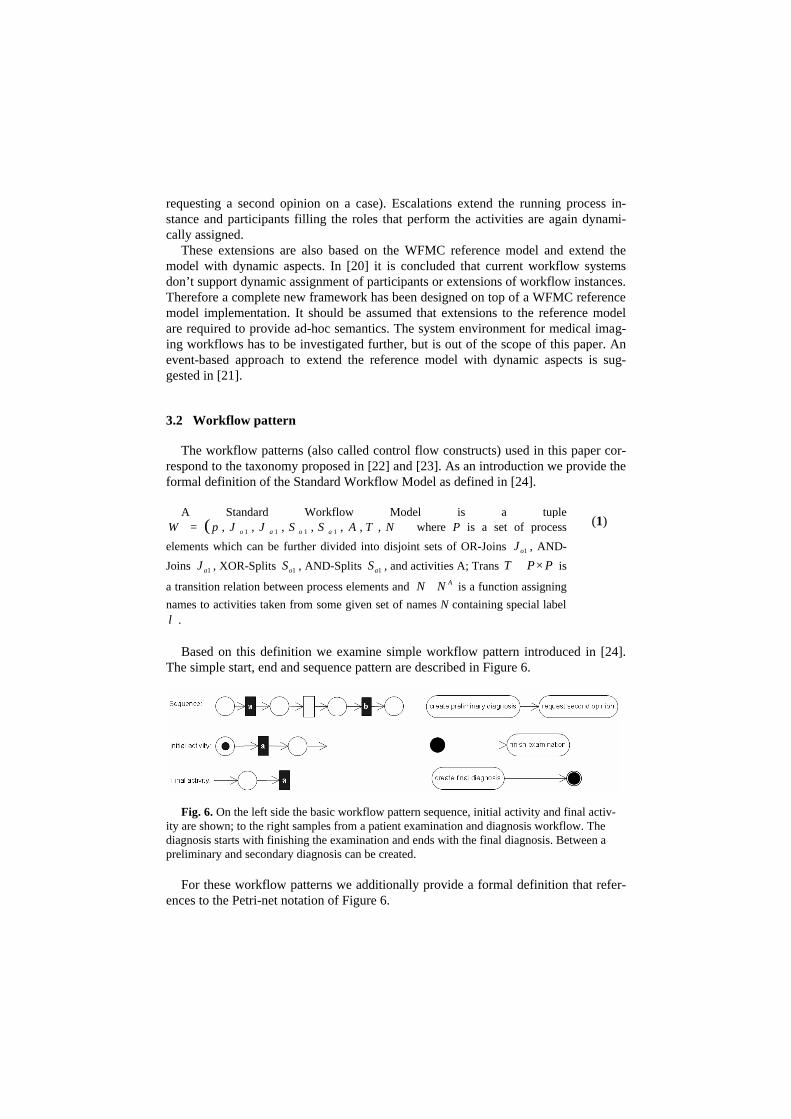
Based on this definition we examine simple workflow pattern introduced in [24].
The simple start, end and sequence pattern are described in Figure 6.
Fig. 6. On the left side the basic workflow pattern sequence, initial activity and final activ-ity are shown; to the right samples from a patient examination and diagnosis workflow. The diagnosis starts with finishing the examination and ends with the final diagnosis. Between a preliminary and secondary diagnosis can be created.
For these workflow patterns we additionally provide a formal definition that refer-
ences to the Petri-net notation of Figure 6.

Sequence ( S ):
{ } Pba ∈, , { }alin ba =)( , , { }blout ba =)( , (2)
Sequence transition:
bas lT ,= , { }btransaLT bas |,= (3)
Initial activity:
{ }rlin ar =)( , , { } Par ∈, , SS I ⊆ , { }alout ar =)( , (4)
Initial places:
{ }atransrLT arIs |,= , { }IxrP xI ∈= | , Pa ∈ ,
IPr ∈ (5)
Final activity:
SS M ⊆ , Pa ∈ , MPm ∈ (6)
Final places:
{ }MxrP xM ∈= | , { }mtransaLT maMS |,= (7)
(2): A sequence S consists of a and b, both elements of the set of Petri-net places P.
The in-operation contains all elements of the places set where there is a link la,b to a transition t. The out-operation contains all elements of the places set where there is a link la,b from a transition t. The in-operation of la,b therefore contains element a and the out-operation element b.
(3): The sequence transition T consists of the links between a and b. (4+5): The initial activity is a special Sequence with an in-operation set that con-
sists of elements from the set of initial places PI (similar for transitions). (6+7): The final activity is a special Sequence with an out-operation set that con-
sists of elements from the set of finale places PM (similar for transitions). Basic workflow pattern describe simple flows of control. Sequences are used for
activities that occur in a specific order. Initial and final activities are start and end points in the workflow. The samples correspond to the workflow introduced in section 4. Beside the basic structures the flow can also be controlled through XOR and OR split and join operations, which will be described next, see Figure 7.
Fig. 7. On the left side the XOR Split pattern is shown. On the right side a sample from a pa-tient examination and diagnosis workflow is provided. Depending on an emergency attribute, different patient registration processes are performed.
Again we provide a formal definition for this workflow pattern that references to
the Petri-net notation of Figure 7.
XOR-Split ( oS ):
oSS ∈01 , 1oS { } Pcba ∈,, (8)

{ }aSin o =)( 1 , { } { }cbSout o ∨=)( 1 { }{ }211,11
,)(| ttSoutyXT oyoSoS =∈= ,
boSXt ,11 = coSXt ,12 =
(8): The XOR Split S0 is defined with an in-operation of element a and an out-
operation with elements b or c (exclusively). The set of transitions Ts0 consists of two elements, one for the transition a-b and one for a-c.
The XOR Split is defined as a point in the workflow process where, based on a de-
cision or workflow control data, one of several branches is chosen [22]. A sample for this construct is the split after a finish examination where a preliminary diagnosis is created before a second opinion is required (see also Section 4). Corresponding to the Split an OR join control flow construct is defined as shown in Figure 8.
Fig. 8. On the left side the OR Join pattern is shown. On the right side a sample from a patient examination and diagnosis workflow is provided. After the registration of a patient multiple execution threads are converged.
The formal definition for the Petri-net notation of Figure 8 is as follows.
OR-Join ( oJ ):
oo JJ ∈1 Pcba ∈},,{ , { })(|, xinyJxQT oyxoJ ∈∧∈=
{ } { }baJin o ∨=)( 1 , { }cJout o =)( 1 { }{ }211,11
,)(| ttJinyQT oyoJoJ =∈=
boJQt,11 = ,
aoJQt,12 =
(9)
(9): The OR Join J0 is defined with an in-operation of element a or b and an out-
operation with element c. The set of transitions TJ0 consists of two elements, one for the transition a-c and one for b-c. This definition can be extended to multiple input places.
The OR join is defined as a point in the workflow process where two or more alter-
native branches come together without synchronization. In other words the merge will be triggered once any of the incoming transitions are triggered [22]. The next con-struct is the AND split as shown in Figure 9.

Fig. 9. On the left side the AND Split pattern is shown. On the right side a sample from a patient examination and diagnosis workflow is provided. When requesting a second opinion there is a DICOM and a HL7 thread, both can be executed in parallel.
The formal definition for the Petri-net notation of Figure 9 is as follows.
AND-Split ( aS ):
aa SS ∈1 , { } Pcba ∈,, { }aSin a =)( 1 , { }cbSout a ,)( 1 =
{ }aaaSas SSRT ∈= 111| ,
11 aSrt =
(10)
(10): The AND Split Sa is defined by an in-operation that consists of the element a and an out-operation that consists of the elements b and c. Sa has only one transition t1 from a to b and c.
The AND Split can be described as a point in the workflow process where a single thread of control splits into multiple treads of control which can be executed in paral-lel, thus allowing activities to be executed simultaneously or in any order [22]. Finally the corresponding AND Join is shown in Figure 10.
Fig. 10. On the left side the AND Join pattern is shown. On the right side a sample from a patient examination and diagnosis workflow is provided. When requesting a second opinion there is a DICOM and a HL7 thread, both can be executed in parallel.
The formal definition for the Petri-net notation of Figure 10 is as follows.
AND-JOIN ( aJ ):
aa JJ ∈1 , { } Pcba ∈,, { }aaJaaJ JJKT ∈= 11 | ,
11 aJKt = (11)

(11): The AND Join Ja is defined by an in-operation that consists of the elements a and b an out-operation that consists of the element c. Ja has only one transition t1 from a and b to c.
The AND Join can be described as a point in the workflow process where multiple parallel sub-processes/activities converge into one single thread of control, thus syn-chronizing multiple threads.
In this section we provided an overview of ad-hoc workflow and basic workflow pattern. These constructs will be used for defining a workflow model in section 4 and a BPEL specification in section 5.
4 Second opinion workflow
In this section we describe the second opinion ad-hoc workflow. The definition is based on UML activity diagrams as a well understood technique. In respect to a BPEL implementation there is currently no generally used graphical notation of workflows. Several different semantics are found in the literature. All of them have some limita-tions and use syntactical extensions to define workflow behavior. Such extensions (ex. branch conditions) are also used here. Requirements for and a detailed analysis of pros and cons of modeling techniques can be found in [6] and [24].
The second opinion scenario is chosen, because it is currently discussed, addresses quality management and the support for the DICOM and HL7 standards is well de-fined and can be interrelated by mapping protocol messages to the workflow model. In the scenario for a second opinion, two medical imaging facilities perform an ad-hoc workflow process. First an institution implements its own workflow for performing a diagnosis on a patient. In certain complicate cases, the radiologist decides to request a second opinion on a case. This ad-hoc behavior can also be compared to the escalation scenario described in [20].
4.1 Second opinion workflow activities
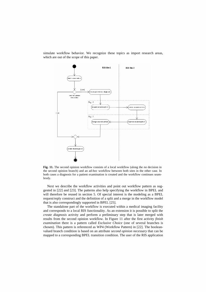
The basis workflow and the ad-hoc extension are shown in Figure 11. The second opinion workflow is executed between two medical imaging facilities. One is the ini-tiator (RIS Site 1) or user the other one is the provider (RIS Site 2) of the second opinion. The required data exchange is handled by the DICOM and HL7 protocol. Of special interest is also the mapping between the workflow model in Figure 11 and the protocol implementation shown in Figures 12 and 13.
First this mapping creates a hierarchical workflow model, where the activities in Figure 11 form super-activities (like super-states in terms of state diagrams) of the protocol communication in the other Figures. Further, a second opinion case requires a workflow implementation for each RIS site. In real-world scenarios one has to deal with legacy applications and equipment that is not workflow-aware, but support DICOM and HL7 protocols. For those scenarios proxy mechanisms should be used to
simulate workflow behavior. We recognize these topics as import research areas, which are out of the scope of this paper.
Fig. 11. The second opinion workflow consists of a local workflow (along the no decision in the second opinion branch) and an ad-hoc workflow between both sites in the other case. In both cases a diagnosis for a patient examination is created and the workflow continues seam-lessly.
Next we describe the workflow activities and point out workflow pattern as sug-gested in [22] and [23]. The patterns also help specifying the workflow in BPEL and will therefore be reused in section 5. Of special interest is the modeling as a BPEL request/reply construct and the definition of a split and a merge in the workflow model that is also correspondingly supported in BPEL [25].
The standalone part of the workflow is executed within a medical imaging facility and corresponds to a local RIS functionality. As an extension it is possible to split the create diagnosis activity and perform a preliminary step that is later merged with results from the second opinion workflow. In Figure 11 after the first activity finish examination there is a pattern called Exclusive Choice (one of several branches is chosen). This pattern is referenced as WP4 (Workflow Pattern) in [22]. The boolean-valued branch condition is based on an attribute second opinion necessary that can be mapped to a corresponding BPEL transition condition. The user of the RIS application

decides to instantiate a second opinion workflow case by case. Such metadata is part of the message exchange and is used as routing information in a Web service based implementation. Further and not shown here the second opinion workflow can be executed several times per case with different business partners. At another point down in the diagram, before the create final diagnosis activity, there is a pattern called Simple Merge (WP5 - two or more alternative branches come together without synchronization). After execution of the second opinion the workflow process contin-ues as in the non ad-hoc scenario by creating a final diagnosis on the case. Another control flow between activities is called Sequence (WP1 - activity enabled after the completion of another activity in the same process). Such sequences are the standard pattern and used throughout the scenario. For example the create second opinion and response second opinion are sequentially, the results of the first activity are inputs in the next processing step.
4.2 Second opinion request activities
Figure 12 and 13 show the details of the HL7 and DICOM message exchange in this workflow. Two phases of interactions occur. In the first phase the patient and image data is provided to RIS Site 2, while in the second phase the diagnosis results are sent back to RIS Site 1. The DICOM and HL7 messages are defined in the stan-dard documents [3], [4]. The selection of the messages has also been based on real-world scenarios already found in data exchange of industry products like Tiani [26] and D.A.T.A. [27]. Again, the used workflow patterns are directly supported by BPEL constructs. What makes this model different from just specifying a message exchange is that these messages are already grouped together meaningfully and can be reused in other BPEL service links. In the first phase (Figure 12) RIS Site 1 communicates patient information using HL7 patient registration messages. The images are transmit-ted using the DICOM C-Store service class implementing a Client/Server model.

Fig. 12. The first detailed view of Figure 11 shows the message exchange between the request second opinion and create second opinion activities of the workflow. The HL7 and DICOM protocols are used to transfer patient and image data between both sites. Depending on the protocol support different interaction scenarios are implemented.
In Figure 12 the first point after the activities request second opinion is a Parallel
Split (WP2 - single thread splits into threads executed in parallel). The HL7 and DICOM activities are allowed to be executed simultaneously and in any order. The branch conditions use boolean-valued expressions for the protocol support of the implementation. The workflow model also works without one of these protocols. Ad-ditionally it is possible to define a proprietary protocol providing the same semantic behavior pointed out for the high-level view. At point emergency there is an Exclusive Choice (WP4) using a corresponding expression. Depending on the case more or less detailed patient information is provided for the remote site. In case of emergency only

a short pre-registration tasks place. Between the HL7 A01 acknowledge and HL7 A04 acknowledge activities there is a Simple Merge (WP5) unifying these cases. After-wards there is a Synchronization point (WP3 - multiple parallel branches converge synchronizing multiple threads). The HL7 and DICOM message exchange is synchro-nized before proceeding creating a second opinion. All other control flows are of the simple pattern type Sequence (WP1).
4.3 Second opinion response activities
Figure 13 contains details of the second part of the workflow. The second opinion created by RIS Site 2 is communicated using HL7 observation messages. The DICOM protocol is not required in this scenario. The scenario could be extended to consider image annotations created during the second opinion process on the remote site.
Fig. 13. A further detailed view of Figure 11 shows the message exchange between the re-sponse second opinion and merge second opinion activities of the workflow. Because results for a diagnosis are provided in text format only the HL7 protocol is most appropriate for this situation.
Next we will examine the workflow pattern. In Figure 13 at the first point between
activities response second opinion and HL7 R01 unsolicited observation message there is an Exclusive Choice (WP4) pattern. Depending on the protocol support the

HL7 protocol is used. Again proprietary protocols can be implemented in accordance to the workflow model. At another point, shown before the merge second opinion activity, there is a Simple Merge (WP5) that synchronizes the cases of protocol sup-port. All other control flows are Sequence pattern (WP1). For example the HL7 A01 admit visit notification and the HL7 A01 acknowledge build such a pattern.
As a conclusion the second opinion workflow can be described using UML activity diagrams. A two level hierarchy with one overview and two detail flows has been defined. In the next section a BPEL specification is provided for the second opinion workflow.
5 BPEL implementation
In this section we provide a BPEL definition of the second opinion workflow. An introduction to BPEL and its terminology is given. We further provide sample map-pings between activity diagrams and BPEL code for higher readability and an anno-tated BPEL and WSDL specification. Because WSDL defines the structure and BPEL the flow of data exchange both definitions are required to provide a good understand-ing of the workflow model’s formal description.
5.1 Introduction and Terminology
BPEL has been designed for modeling workflows. It additionally focuses on cur-rent Web service based environments and is based on XML notation and WSDL ser-vice descriptions as well understood concepts. In workflow terminology BPEL defines activities and their relationship in a flow style of XPath [28] or a directed graph style of WSFL [29]. Several language constructs for branching and merging are provided that support the pattern used in the second opinion workflow definition. BPEL defines the partners interacting in a workflow, the services and the roles each partner has. Business processes specified via BPEL prescribe the exchange of messages between Web services. These messages are WSDL messages of operations of the port types involved in the roles of the service links established between the process and its part-ners [17]. For a better orientation we shortly introduce major terms used in the WSDL and BPEL specification.
Partners, Roles, Port Types and Service Link Types
WSDL and BPEL define business partners that provide and consume services and can take several roles in a workflow model. Services partition the workflow model of partners and their activities normally into two or more partners and one or more activi-ties. The port types (service interfaces) are defined by operations and the exchange of messages. Normally services use producer/consumer or client/server semantics, lead-ing for example to a producer and consumer port definition and a client and server role. A service link type relates such services to the workflow model. It defines which

business partner performs which role and the port types it communicates through. During runtime specific ports, corresponding to a port type, are used to define addi-tional connection parameters, security properties, etc. What’s sometimes misleading is that WSDL provides interface definitions through port types and service link types. The services themselves are not explicitly defined.
Operations, Messages, Context
Each port type defined in a WSDL file consists of one or several operations per-formed between the partners. The flow of operations is defined in the BPEL file. An operation consists of one or more input and output messages. Each message consists of workflow data and context data for security, transactions, etc.
Variables, Expressions, Conditions, Correlations
Variables are used to store message data of stateful workflow interactions. X-Path [30] like expressions (boolean, deadline-based, general) can be defined using variable definitions. These expressions can be used for branch conditions and other dependent operations. Message parts can be correlated by defining relations between variables in two or more messages. The variable content can also be copied for message ID-like semantics.
Simple and complex activities
Activities are the building blocks of the BPEL workflow definition. Simple activi-ties like receive, reply, invoke, wait define communication pattern for initiating or waiting for operations, time triggered operations, etc.; further more are defined. Com-plex activities like flow (for ordering activities), link (for graph-like linking of activi-ties), scope (for grouping activities), sequence, switch and while (for flow control) provide workflow pattern for relating simple activities.
5.3 BPEL patterns
With BPEL we have a basis for a detailed workflow specification. However BPEL doesn’t provide a graphical representation and common representations for workflows have their pros and cons [6], [24]. We have chosen activity diagrams because it is well understood and supports BPEL language constructs. We are therefore able to derive BPEL language pattern from the workflow pattern identified in section 4. We provide a short pattern analysis as suggested in [25]. The approach chosen here suggests that the mapping of workflow patterns can be automated. Such automation would enhance integrity and consistency of the workflow model and its implementation specification similar to techniques used for class diagrams in software development.

AND Split and Join pattern, flow construct
The first patterns we examine is the AND Split and the AND Join. As shown in Fig-ure 12 such constructs are used to execute the DICOM and HL7 implementation in parallel. The BPEL language provides the flow statement to define this relationship between activities. Figure 14 compares the workflow patterns with the BPEL con-struct.
<!— AND Split --> <flow> <!-- HL7 flow --> </flow> <flow> <!-- DICOM flow --> </flow>
Fig. 14. shows a sample comparison of AND Split and AND Join workflow patterns and the BPEL flow construct. The sample shows the split for HL7 and DICOM protocol support. The corresponding BPEL file consists of two parallel flows for each implementation.
On the left side the workflow patterns enable parallel execution of tasks. This functionality
is reached using the flow construct in BPEL. In our case the HL7 and DICOM support are executed in parallel. The constructs are used like in programming languages and can be nested, have conditions, etc.
XOR Split and OR Join pattern, switch construct
The next patterns compared are the XOR Split and OR Join. As shown in Figure 12 such constructs are used to specify DICOM and HL7 protocol support. The BPEL language provides the switch statement to define this relationship between activities. Figure 15 compares the workflow patterns with the BPEL construct.
<switch> <!-- switching HL7 support --> <case hl7support=false> <!-- HL7 flow empty --> </case> <case hl7support=true> <!-- HL7 flow continues --> </case> </switch> <!-- HL7 support -->
Fig. 15. shows a sample comparison of XOR split and OR join workflow patterns and the

BPEL switch construct. The sample describes the alternative threads for a registration of a patient in case or without an emergency. The BPEL file implements this behavior with the switch construct.
On the left side the workflow patterns enable exclusively one execution of two or
more tasks. This functionality is reached using the switch construct in BPEL. In our case depending whether HL7 is supported by the application or not the corresponding workflow functionality is executed.
5.4 BPEL specification
In this section we provide a WSDL and BPEL specification for the second opinion workflow. The source code is commented for each section following the structure in [2]. The WSDL file is not part of the BPEL specification but improves understanding of the language constructs. The WSDL file defines the content and structure of com-munication. The business partners and the flow of interaction are defined in the BPEL file. Messages, port types and service link types of the WSDL definitions are refer-enced.
WSDL and BPEL definition of high level workflow
The high level workflow corresponds to Figure 11. The WSDL file contains the message, port type and service link type definition as shown in the following listing.
WSDL file for the high level workflow
<!-- HIGH-LEVEL Workflow of Figure 11 --> <!-- WSDL definition --> <definitions targetNamespace="http://data.at/wsdl"
xmlns:wf="http://data.at/wsdl/ris"> <!-- message definitions --> <message name="Request Second Opinion"> <part name="WF SO metadata" type="wf_so_meta"> <part name="WF SO data" type="wf_so"> </message> <message name="Response Second Opinion"> <part name="WF SO metadata" type="wf_so_meta"> <part name="WF SO data" type="wf_so"> </message> <!-- port type definitions (SO abbreviates second opinion) --
> <portType name="SOSecondaryWFPort"> <operation name="Request Second Opinion">

<input message="Request Second Opinion"> </operation> </portType> <portType name="SOPrimaryWFCallbackPort"> <operation name="Response Second Opinion"> <input message="Response Second Opinion"> </operation> </portType> <!-- service link type definitions --> <serviceLinkType name="SecondaryOpinionWFLT"> <role name="SOPrimary"> <portType name="SOPrimaryWFCallbackPort"> </role> <role name="SOSecondary"> <portType name="SOSecondaryWFPort"> </role> </serviceLinkType> On top of the file there is a namespace definition for WSDL elements. Next two
message definitions for the data exchange during the Request Second Opinion and Response Second Opinion activities are defined. Both messages consist of a metadata and a message body. The metadata is intended for additional information about com-munication partners and other administrative data. Afterwards the port types are de-fined. The SOSecondaryWFPort and SOPrimaryWFCallbackPort port types corre-spond to the roles the RIS site hold. Important is the definition of the callback port to enable the workflow engine to execute the model with asynchronous communication behavior. While the name doesn’t influence the behavior it is easier to model BPEL activities for sending and receiving operations, if the corresponding ports are clearly defined. Finally the file contains a service link type definition. Here the Secon-daryOpinionWFLT link type is defined which contains a definition of two RIS sites. The sites provide the port types from above and the roles SOPrimary and SOSecon-dary which are equal to the RIS Site 1 and RIS Site 2 definition in Figure 11.
BPEL file for the high level workflow
<!-- BPEL definition -->
<process name="secondOpinion" targetNamespace="http://data.at/bpel/secondopinion"> xmlns="http://schemes.xmlsoap.org/ws/2003/03/business-
process/" xmlns:wf="http://data.at/wsdl/ris" xmlns:lns="http://data.at/wsdl">
<!-- partner definitions -->
<partners> <partner name="secondarySite" serviceLinkType="SecondaryOpinionLT" myRole="SOPrimary"

partnerRole="SOSecondary"/> </partners> <!-- variable definitions -->
<variables> <variable name="WF_SO_REQ" messageType="wf:Request Second Opinion">
<variable name="WF_SO_RESP" messageType="wf:Response Second Opinion"> </variables> <!-- workflow definition -->
<sequence> <!—- serializing request / response messages -->
<invoke partner="secondarySite"
portType="SOSecondaryWFPort" operation="Request Second Opinion" inputvariable="WF_SO_REQ"> <correlations> <correlation set="WF_SO"> </correlations>
</invoke>
<invoke partner="secondarySite" portType="SOPrimaryWFCallbackPort" operation="Response Second Opinion" inputvariable="WF_SO_RESP"> <correlations> <correlation set="WF_SO"> </correlations>
</invoke>
</sequence> <!—- serializing request / response messages -->
The BPEL file contains a namespace definition of the workflow namespace from the above WSDL file, a BPEL specific name space and a local namespace of the BPEL file. Next there is a partner definition where the secondary site is defined. For each service link type a partner and the own and the partners role are defined. In this case the primary and secondary second opinion roles are listed. Finally one variable per workflow message is defined. The second part of the definition contains the high level workflow itself, corresponding to the definition in Figure 11. The sequence con-struct serializes the second opinion request and response. Both operations are per-formed using the invoke activity. A correlation set is defined to create a logical rela-tionship between the request and response message content.
With these definitions an implementation of the high level workflow can be de-rived. The definition corresponds to the system interface shown in Figure 10. Collaxa [31] is a very current product development that supports definition and execution of BPEL models. However, a working sample has been out of the scope of this paper.

WSDL and BPEL definition of HL7/DICOM second opinion request
The communication between the two radiological sites is not only based on a work-flow model but also on HL7 and DICOM messages exchange. To define the corre-sponding interface and message exchange, a WSDL and BPEL description is pro-vided. The source code below shows the WSDL file defined for the second opinion request. Because of the length of the definition the WSDL and BPEL files are split into two parts.
WSDL file for the DICOM / HL7 Second Opinion Request (Part 1)
<!—- DICOM / HL7 Workflow of Figure 12 --> <!-- WSDL definition -->
<definitions targetNamespace="http://data.at/wsdl" xmlns:hl7="http://data.at/wsdl/hl7" xmlns:dicom="http://data.at/wsdl/dicom" xmlns:ris="http://data.at/wsdl/ris">
<!-- message definitions -->
<message name="HL7 A04 register a patient"> <part name="RIS HL7 metadata" type="ris_hl7"> <part name="HL7 A04 data" type="hl7_a04"> </message>
<message name="HL7 A04 acknoledge"> <part name="RIS HL7 metadata" type="ris_hl7"> <part name="HL7 A04 data" type="hl7_a04"> </message>
<message name="HL7 A01 admit visit notification"> <part name="RIS HL7 metadata" type="ris_hl7"> <part name="HL7 A01 data" type="hl7_a01"> </message>
<message name="HL7 A01 acknoledge"> <part name="RIS HL7 metadata" type="ris_hl7"> <part name="HL7 A01 data" type="hl7_a01"> </message>
<message name="DICOM Association Request">
<part name="RIS DICOM metadata" type="ris_dicom"> <part name="DICOM Association Request data"
type="dicom:associationRequest"> </message>
<message name="DICOM Association Response">
<part name="RIS DICOM metadata" type="ris_dicom"> <part name="DICOM Association Response data"
type="dicom:associationResponse"> </message>
<message name="DICOM C-STORE">

<part name="RIS DICOM metadata" type="ris_dicom"> <part name="DICOM C-STORE data" type="dicom_cstore">
</message>
<message name="DICOM Study End"> <part name="RIS DICOM metadata" type="ris_dicom"> <part name="DICOM Study End data" type="dicom_studyEnd">
</message>
<message name="DICOM Association Release"> <part name="RIS DICOM metadata" type="ris_dicom"> <part name="DICOM Association Release"
type="dicom_associationRelease"> </message>
The WSDL definition again contains a namespace definition for the RIS, the HL7
and the DICOM implementation. Then the message definition contains everything required by the activity diagram in Figure 12. Every message is named in consistence to the protocol standard specification. As above two message parts for metadata and application data are considered. The following source code contains port type and service link type specifications.
WSDL file for the DICOM / HL7 Second Opinion Request (Part 2)
<!-- port type definitions (SO abbreviates second opinion) -->
<portType name="SOSecondaryHL7Port"> <operation name="HL7 A04 register a patient"> <input message="HL7 A04 register a patient"> </operation> <operation name="HL7 A01 admit visit notification"> <input message="HL7 A01 admit visit notification"> </operation>
</portType>
<portType name="SOPrimaryHL7CallbackPort"> <operation name="HL7 A04 acknoledge"> <input message="HL7 A04 acknoledge"> </operation> <operation name="HL7 A01 acknoledge"> <input message="HL7 A01 acknoledge"> </operation>
</portType>
<portType name="SOSecondaryDICOMPort"> <operation name="DICOM Association Request"> <input message="DICOM Association Request"> </operation> <operation name="DICOM C-STORE"> <input message="DICOM C-STORE"> </operation>
</portType>

<portType name="SOPrimaryDICOMCallbackPort">
<operation name="DICOM Association Response"> <input message="DICOM Association Response">
</operation> </portType>
<!-- service link type definitions -->
<serviceLinkType name="SecondaryOpinionDicomLT"> <role name="SOPrimary">
<portType name="SOPrimaryDICOMCallbackPort"> </role> <role name="SOSecondary"> <portType name="SOSecondaryDICOMPort"> </role>
</serviceLinkType>
<serviceLinkType name="SecondaryOpinionHL7LT"> <role name="SOPrimary"> <portType name="SOPrimaryHL7CallbackPort"> </role>
<role name="SOSecondary"> <portType name="SOSecondaryHL7Port">
</role> </serviceLinkType>
WSDL ports and service link types for the second opinion request are defined. For
both sites a HL7 and a DICOM port is specified, resulting in four port type defini-tions. Two of which are for the initiating operations and two for a callback interface on the secondary site. The callback interface is required for the asynchronous response Finally there is a HL7 and a DICOM service link type linking the primary and the secondary site together based on the defined port types for each protocol. Interesting is the workflow definition which is presented as source code next.
BPEL file for the DICOM / HL7 Second Opinion Request (Part 1)
<!-- BPEL definition -->
<process name="secondOpinionRequest"
targetNamespace="http://data.at/bpel/secondopinion"> xmlns="http://schemes.xmlsoap.org/ws/2003/03/business-
process/" xmlns:hl7="http://data.at/wsdl/hl7" xmlns:dicom="http://data.at/wsdl/dicom" xmlns:ris="http://data.at/wsdl/ris" xmlns:lns="http://data.at/wsdl">
<!-- partner definitions -->
<partners> <partner name="secondarySite" serviceLinkType="SORequestSecondarySiteLT" myRole="SORequestSecondarySiteUser"/>

</partners>
<!-- variable definitions -->
<variables> <variable name="HL7_A04_RAP" messageType="hl7:HL7 A04 regis-
ter a patient"> <variable name="HL7_A04_ACK" messageType="hl7:HL7 A04 ac-
knoledge"> <variable name="HL7_A01_AVN" messageType="hl7:HL7 A01 admit
visit notification"> <variable name="HL7_A01_ACK" messageType="hl7:HL7 A01 ac-
knoledge"> <variable name="DICOM_ASSOC_REQ" messageType="dicom:DICOM
Association Request"> <variable name="DICOM_ASSOC_RESP" messageType="dicom:DICOM
Association Response"> <variable name="DICOM_C-STORE" messageType="dicom:DICOM C-
STORE"> <variable name="DICOM_C-STORE_STUDY_END"
messageType="dicom:DICOM C-STORE Study End"> <variable name="DICOM_ASSOC_REL" messageType="dicom:DICOM
Association Release"> </variables>
The BPEL definitions start with the namespace specification which has to fit to the
corresponding WSDL file. Afterwards the secondary partner and variables for every exchanged DICOM and HL7 message are defined.
BPEL file for the DICOM / HL7 Second Opinion Request (Part 2)
<!-- workflow definition -->
<sequence> <!-- parallelizing of DICOM and HL7 support --> <flow> <!-- HL7 flow --> <switch> <!-- switching HL7 support -->
<case WF_SO_REQ.hl7support=false> <!-- HL7 flow empty --> </case>
<case WF_SO_REQ.hl7support=true> <!-- HL7 flow continue --> <switch> <!-- switching emergency --> <case WF_SO_REQ.emergency=true> <!-- HL7 emergency flow --> <invoke partner="secondarySite" portType="SOSecondaryHL7Port" operation="HL7 A04 register a patient" inputvariable="HL7_A04_RAP" <correlations> <correlation set="HL7_A04"> </correlations> </invoke> <receive partner="secondarySite"

portType="SOPrimaryHL7CallbackPort" operation="HL7 A04 acknoledge" inputvariable="HL7_A04_ACK" <correlations> <correlation set="HL7_A04"> </correlations> </receive> </case> <case emergency=false> <!-- HL7 normal flow --> <invoke partner="secondarySite" portType="secondaryOpinionHL7Port" operation="HL7 A01 admit visit notification" inputvariable="HL7_A01_AVN"> <correlations> <correlation set="HL7_A01"> </correlations> </invoke> <receive partner="secondarySite" portType="primaryOpinionHL7CallbackPort" operation="HL7 A01 acknoledge" inputvariable="HL7_A01_ACK"> <correlations> <correlation set="HL7_A01"> </correlations> </receive> </case>
</switch> <!-- emergency --> </switch> <!-- hl7support --> </flow> <!-- HL7 flow -->
The second part of the file contains the workflow definition and starts with the se-
quence tag. Together with two flow tags the HL7 and DICOM support can be parallel-ized. Therefore the flow tag for the HL7 follows and a switch for the HL7 support and the emergency case are considered. Depending on these parameters the corresponding HL7 messages are exchanged using invoke and receive activities. The communication is synchronous like the protocol implementation. The ports are defined as callback ports to distinguish between acting and reacting behavior in the workflow. The follow-ing sample contains the rest of this BPEL file.
BPEL file for the DICOM / HL7 Second Opinion Request (Part 3)
<flow> <!-- DICOM flow -->
<switch> <!-- switching DICOM support -->
<case WF_SO_REQ.dicomsupport=false> <!-- DICOM flow empty -->
</case>

<case dicomsupport=true> <!-- DICOM flow continues -->
<invoke partner="secondarySite" portType="SOSecondaryDICOMPort" operation="DICOM Association Request" inputvariable="DICOM_ASSOC_REQ"> <correlations> <correlation set="DICOM_ASSOC"> </correlations> </invoke> <receive partner="secondarySite" portType="SOPrimaryDICOMCallbackPort" operation="DICOM Association Response" inputvariable="DICOM_ASSOC_RESP"> <correlations> <correlation set="DICOM_ASSOC"> </correlations> </receive> <invoke partner="secondarySite" portType="SOSecondaryDICOMPort" operation="DICOM C-STORE" inputvariable="DICOM_C-STORE"> <correlations> <correlation set="DICOM_C-STORE"> </correlations> </invoke> <invoke partner="secondarySite" portType="SOSecondaryDICOMPort" operation="DICOM C-STORE Study End" inputvariable="DICOM_C-STORE_STUDY_END"> <correlations> <correlation set="DICOM_C-STORE"> </correlations> </invoke> <invoke partner="secondarySite" portType="SOSecondaryDICOMPort" operation="DICOM Association Release" inputvariable="DICOM_ASSOC_REL"> <correlations> <correlation set="DICOM_ASSOC"> </correlations> </invoke>
</case> <!-- DICOM flow continues --> </switch> <!-- switching DICOM support --
> </flow> <!-- DICOM flow --> </sequence> <!-- parallelizing of DICOM and HL7 support -->
</process>

The DICOM part of the definition is similar to the HL7 specification. The opera-
tions are performed using invoke and receive activities and a switch distinguishes between protocol support.
WSDL and BPEL definition of HL7/DICOM second opinion response
Finally the third definition is provided. The WSDL and BPEL files for the Re-sponse Secondary Opinion part of the workflow are defined in this section.
WSDL file for the DICOM / HL7 Second Opinion Response
<!—- DICOM / HL7 Workflow of Figure 13 --> <!-- WSDL definition -->
<definitions targetNamespace="http://data.at/wsdl"
xmlns:hl7="http://data.at/wsdl/hl7" xmlns:dicom="http://data.at/wsdl/dicom" xmlns:ris="http://data.at/wsdl/ris" >
<!-- message definitions -->
<message name="HL7 R01 unsolicited observation message"> <part name="RIS HL7 metadata" type="ris_hl7"> <part name="HL7 R01 data" type="hl7_r01"> </message>
<message name="HL7 R01 acknoledge"> <part name="RIS HL7 metadata" type="ris_hl7"> <part name="HL7 R01 data" type="hl7_r01"> </message>
<!-- port type definitions (SO abbreviates second opinion) -->
<portType name="SOPrimaryHL7CallbackPort"> <operation name="HL7 R01 unsolicited observation message"> <input message="HL7 R01 unsolicited observation message"> </operation> </portType>
<portType name="SOSecondaryHL7Port"> <operation name="HL7 R01 acknoledge"> <input message="HL7 R01 acknoledge"> </operation> </portType>
First the namespaces for the RIS, HL7 and DICOM parts are defined. Next the HL7 observation messages are defined. Finally two port types for the primary callback interface and the secondary interface are listed. Again the communication is synchro-

nous, but this way it is easier to distinguish acting behavior in the workflow. Finally the workflow of the response is provided.
BPEL file for the DICOM / HL7 Second Opinion Response
<!-- BPEL definition -->
<process name="secondOpinionResponse" targetNamespace="http://data.at/bpel/secondopinion">
xmlns="http://schemes.xmlsoap.org/ws/2003/03/business-process/"
xmlns:hl7="http://data.at/wsdl/hl7" xmlns:dicom="http://data.at/wsdl/dicom" xmlns:ris="http://data.at/wsdl/ris" xmlns:lns="http://data.at/wsdl">
<!-- partner definitions -->
<partners> <partner name="secondarySite" serviceLinkType="SOResponseSecondarySiteLT"
myRole="SOResponseSecondarySiteUser"/> </partners>
<!-- variable definitions -->
<variables> <variable name="HL7_R01_UOM" messageType="hl7:HL7 R01 unsolic-ited observation message">
<variable name="HL7_R01_ACK" messageType="hl7:HL7 R01 ac-knoledge"> </variables>
<!-- workflow definition -->
<flow> <!-- HL7 flow -->
<switch> <!-- switching HL7 support -->
<case WF_SO_REQ.hl7support=false> <!-- HL7 flow empty -->
</case> <!-- HL7 flow empty -->
<case hl7support=true> <!-- HL7 flow continues -->
<receive partner="secondarySite"
portType="SOPrimaryHL7CallbackPort" operation="HL7 R01 unsolicited observation message" inputvariable="HL7_R01_UOM">
<correlations> <correlation set="HL7_R01"> </correlations> </receive>
<invoke partner="secondarySite"
portType="SOSecondaryHL7Port"

operation="HL7 R01 acknoledge" inputvariable="HL7_R01_ACK"> <correlations> <correlation set="HL7_R01"> </correlations>
</invoke> </case> <!-- HL7 flow continues --> </switch> <!-- switching HL7 support --> </flow> <!-- HL7 flow --> </process>
The workflow definition distinguishes the case of HL7 support, performs a R01 op-
eration and requires its acknoledge. Again a callback port describes the communica-tion direction. The partners and variables are consistent with the definitions above.
Limitations of the definitions
Finally we summarize which features haven’t been considered in the BPEL defini-tion. There is no scope definition, because we think more experience is required to argue a specific design decision. One possibility is the specification of a scope per protocol, because the HL7 and DICOM flows are independent and produce different errors through external applications. A further separation can be made between the request and response of the second opinion, depending on whether this is seen as a single transaction; in real-world this is normally not the case. The definition of name-spaces is performed exemplary but not used throughout the sample. Further missing are links, because the mapping just uses XLang [28] specific constructs. Fault and compensation handler haven’t been used. All those language extensions should be investigated in further workflow scenarios, especially scopes are identified as an im-portant research area. Methods to automate the creation of BPEL specifications would further be beneficial. Additionally an implementation and simulation of a workflow model is necessary to conclude the suitability of BPEL for the medical imaging do-main.
6 Conclusions and Future work
In this paper we analyzed a frequently found ad-hoc workflow in the medical imaging domain: the second opinion workflow. This ad-hoc workflow is a well-suited candi-date for modeling an enactment using Web services technologies. The contribution of this paper was to analyze the requirements of the second-opinion workflow and sec-ondly to show how the ad-hoc workflow can be modeled using the BPEL language. Since this workflow, by its nature, involves other (increasingly ubiquitous) informa-tion systems (e.g. imaging equipment), it may serve as a test case for the applicability and suitability of BPEL in the medical imaging domain. The suggested workflow model covers implementation relevant aspects of the DICOM and HL7 protocols while maintaining an abstract domain model. For now, we conclude that BPEL is

suitable, but several additional research topics have to be covered. Methods to auto-mate the creation of BPEL specifications would be beneficial. Especially the imple-mentation and simulation of a workflow model is necessary to conclude the suitability of BPEL for the medical imaging domain. In our future work we plan to implement models in medical organizations and to analyze further results in the applicability of Web services workflows in the medical imaging domain.
References
1. Workflow Management Coalition: WMFC Reference Model, www.wfmc.org (1995) 2. BEA Systems, IBM, Microsoft, SAP AG and Siebel Systems: Business Process Execution
Language for Web Services version 1.1, http://www-106.ibm.com/developerworks/library/ws-bpel/ (2003)
3. HL7 Organization: Health Level 7, http://www.hl7.org (2000) 4. NEMA and Global Engineering Group: DICOM 3 Standard, http://www.nema.org (1998) 5. CEN/TC251, Health informatics - Medical data interchange: HIS/RIS-PACS and HIS/RIS -
Modality Interface - ENV 13939, http://www.centc251.org/ (2001) 6. van der Aalst, W.M.P., Weske, M., Wirtz G.: Advanced topics in workflow management:
issues, requirements and solutions 7. W3C: Web Services Description Language (WSDL) 1.1, http://www.w3.org/TR/wsdl.html
(2001) 8. Siegel, Eliot, Kolodner, Robert M.: Filmless Radiology, Springer (1998) 9. Huang, H. K.: PACS: Basic Principles and Applications, Wiley-Liss (1998) 10. Anzböck, R.: XR PACS Architektur, D.A.T.A. Corporation, http://www.data.at (2001) 11. Anzböck, R., Dustdar, S.: Interorganizational Workflow in the Medical Imaging Domain.
Proceedings of the 5th International Conference on Enterprise Information Systems (ICEIS), Angers, France, Kluwer Academic Publishers (2003)
12. Anzböck, R.: XR OPEN RIS Architektur, D.A.T.A. Corporation, http://www.data.at (2001) 13. Kreider, N.A., Haselton, B.J.: The Systems Challenge: Getting the Clinical Information-
Support You Need to Improve Patient Care, Wiley, John & Sons, Incorporated (1997) 14. Revet, Bas: DICOM Cookbook, Philips Medical Systems (1997) 15. Oosterwijk, H.: DICOM Basics, OTech Inc/Cap Gemini Ernst and Young 16. Object Management Group (OMG): UML 2.0 Standard specification, http://www.omg.org
(2003) 17. Fowler, Martin, Scorr, Kendall: UML destilled, Addison Wesley Professional (2000) 18. Von der Aalst, W.M.P., Weske, M.: Process-oriented Architectures for Electronic Com-
merce and interorganizational workflow, Eindhoven University of Technology (2001) 19. Von der Aalst, W.M.P., van Hee, K.: Workflow Management, Models, Methods and Sys-
tems, Academic Service (1997) 20. Georgakopoulos, D., Schuster H., Baker, D., Cichocki A.: Managing Escalation of Collabo-
ration Processes in Crisis Mitigation Situations, Proceedings of the 16th Int. Conference on Data Engineering (ICDE’2000), San Diego (2000)
21. Geppert A., Tombros D.: Event-based Distributed Workflow Execution with EVE, Depart-ment of Computer Science, University of Zurich, Technical Report 96.05 (1996, 1998)
22. van der Aalst, W.M.P., ter Hofstede, A.H.M., Kiepuszewski, B., and Barros, A.P.: Work-flow Patterns (2002)
23. van der Aalst, W.M.P., Barros, A.P., ter Hofstede, A.H.M. and Kiepuszewski, B.: Ad-vanced Workflow Patterns (2002)

24. Kiepuszewski, B., ter Hofstede, A.H.M., van der Aalst, W.M.P.: Fundamentals of Control Flow in Workflows (2002)
25. Wohed, P., van der Aalst, W.M.P., Dumas, M., ter Hofstede, A.H.M.: Pattern Based Analy-sis of BPEL4WS, Department of Computer and Systems Sciences, Stockholm Univer-sity/The Royal Institute of Technology, Sweden (2003)
26. Tiani, http://www.tiani.com (2003) 27. D.A.T.A. Corporation, http://www.data.at (2003) 28. Microsoft Corporation: XLANG: Web Services for Business Process Design,
http://www.gotdotnet.com/team/xml_wsspecs/xlang-c/default.htm (2001) 29. IBM: Web Services Flow Language (WSFL 1.0), http://www-
3.ibm.com/software/solutions/webservices/pdf/WSFL.pdf (2001) 30. W3C: XML Path Language (XPath)
Version 1.0, http://www.w3.org/TR/xpath (1999) 31. Collaxa: Collaxa 2.0 BPEL Server, http://www.collaxa.com (2003)