modeling a pawn page 1 of 21 - polynetpolynet.dk/cad/modeling_of_three_chessmen.pdf · than a...
TRANSCRIPT

Tutorial
Modeling a Pawn In this lesson, you will model a pawn for a set of chessmen. In a wooden chess set of standard design, pawns are turned on a lathe. You will use 3ds max to do something similar: draw the pawn's outline, and then use a Lathe modifier to fill out its geometry. The Lathe modifier revolves the outline around a central point to create a shape, not unlike the way wood is turned on a machine lathe.
Features and techniques covered in this lesson:
� Using spline shapes to draw an outline of an object.
This lesson also briefly introduces you to spline editing.
Splines are a type of curve that is interpolated between two endpoints and two or more tangent vectors. The term dates from 1756, and derives from a thin wood or metal strip used for drafting curves in architecture and ship design.
� Using 2D snap to help control spline drawing.
� Using the Lathe modifier to turn a 2D outline into a 3D model.
Skill Level: Beginner
Time to complete: 15 minutes
Set up the lesson:
� Start 3ds max or choose File > Reset if the program is already running.
No startup file is necessary for this tutorial.
Set up the grid and 2D snap:
You need to choose 2D snap options that will help you draw the outline. 2D snap can snap to the home grid that appears in viewports, or to other geometry in the scene. You also need to adjust the home grid so it is easy to see your work.
1. On the toolbar, click and hold down the Snap flyout and choose the 2D snap type.
The 2D Snap Toggle is located on a flyout of 2D/3D snap options.
Page 1 of 21Modeling a Pawn

2. Right-click the 2D Snap Toggle. The Grid And Snap Settings dialog appears.
3. On the dialog's Snaps tab, turn on Grid Points and Grid Lines.
4. On the dialog's Options tab, set Snap Preview Radius to 10, and set Snap Radius to 10.
5. Close the Grid And Snap Settings dialog by clicking the X button in the upper-right corner ofthe dialog's window.
Warning: The Clear All button at the bottom of the dialog clears all your snapsettings. It is easy to confuse this button with a Close button!
6. In the Front viewport, and Zoom in until the viewport is a little over 10 grid squares high.
Now you are ready to begin drawing.
Start the pawn's outline:
You will draw the pawn's outline from the top down, beginning with the “knob” on top.
1. On the Create panel, click Shapes , then click Arc.
2. Make sure that 2D Snap is turned on.
3. In the Front viewport, drag from a grid point near the top center, to the point one square to theright and two squares down. Release the mouse, then drag until you have an arc to the rightside that corresponds to the top of the pawn.
The top of the arc should not rise much above the grid line (otherwise, the pawn will result witha dent on top).
First draw an arc like this.
Yellow snap indicators should appear while your cursor is over a grid point or a grid line.
4. For the body of the pawn, click Line. Draw a zigzag downward from the grid point where youfinished the Arc. Drag from that point to the bottom edge of the same square. Click to set thenew point, then drag horizontally to the grid point on the left. Click to set another point. Finally,drag to the point two squares down and one to the right. Click to set the last point of the Line,and then right-click to end Line creation.
Page 2 of 21Modeling a Pawn

Next draw a zigzag line.
5. The top of the base of the pawn has a small ledge. Draw this as another Line with twosegments: just drag to the right a bit, click, and then drag down (ignoring snaps for the lastpoint). Right-click to complete this Line.
Add the ledge
You are now ready to complete the base.
Complete the pawn's outline:
1. Right-click 2D Snap again. In the Grid And Snap Settings dialog, make sure Endpoint ison. (Leave Grid Points and Grid Lines turned on as well.) Because you didn't use snap for the end of the last Line, you need something else to “grab onto” while completing the outline.
2. Close the Grid And Snap Settings dialog by clicking the X button in the upper-right corner ofthe dialog's window.
3. Make sure that 2D Snap is turned on.
4. Turn on Arc again. Drag from the endpoint of the line that forms the “ledge” at the top of thebase, to the grid point of the next square down, and to the right of the ledge.
Page 3 of 21Modeling a Pawn

5. For the last bit of the base, click Arc. Drag from the grid point where the second Arc ends,to the right a bit, then release the mouse and drag down a bit to curve the line segment.
This little Arc segment can be the trickiest part of the outline to create.
6. Finally, drag a Line from the end of the Arc, horizontally leftward to the grid line that is beneath thepoint where you began the outline.
Modeling a Pawn Page 4 of 21

Finish the lathe profile
7. Turn off 2D Snap.
8. Save the file as my_pawn.max.Tip: Make a MyTutorials folder on your hard disk to store the files you create withthese tutorials.
Edit the outline:
Tip: At this point, you can continue with the file you created in the previous steps, or you can open the file pawn_outline_completed.max, and continue from there.
Before you use the Lathe modifier, the outline should be consolidated into a single spline, rather than a collection of individual spline objects. To do this, you convert it to an Editable Spline.
1. In the Front Viewport select the arc at the top of the pawn's outline.
2. Right-click, and on the Transform (lower-right) quadrant of the quad menu, choose ConvertTo > Convert To Editable Spline.
3. Go to the Modify panel. In the name field at the top of the panel, rename the object from Arc01 to Pawn.
4. On the Geometry rollout, click Attach, and then click each of the other splines that make upthe outline.
Now the pawn outline is a single object.
Modeling a Pawn Page 5 of 21
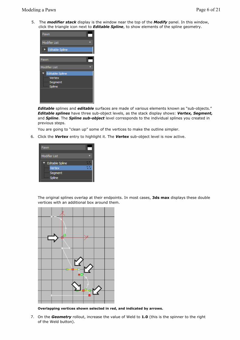
Editable splines and editable surfaces are made of various elements known as “sub-objects.” Editable splines have three sub-object levels, as the stack display shows: Vertex, Segment, and Spline. The Spline sub-object level corresponds to the individual splines you created in previous steps.
You are going to “clean up” some of the vertices to make the outline simpler.
6. Click the Vertex entry to highlight it. The Vertex sub-object level is now active.
The original splines overlap at their endpoints. In most cases, 3ds max displays these double vertices with an additional box around them.
Overlapping vertices shown selected in red, and indicated by arrows.
7. On the Geometry rollout, increase the value of Weld to 1.0 (this is the spinner to the rightof the Weld button).
Modeling a Pawn Page 6 of 21
5. The modifier stack display is the window near the top of the Modify panel. In this window,click the triangle icon next to Editable Spline, to show elements of the spline geometry.

8. Click Select (this turns off Attach). Select the upper overlapping endpoints by dragging abox around them. (Just clicking might select only one of the two vertices.) Then hold down CTRL while you drag a select box around the other overlapping endpoints.
9. Click Weld. Look in the Geometry rollout, further down.
The outline is now a single spline, instead of the six original ones. It has fewer vertices, and no redundant ones.
10. Choose File > Save.
Turn some vertices into corners:Sometimes curvature can “creep in” to a spline. To avoid this, and to get a clean top to the pawn, you will make some vertices into Corner vertices.
1. Right-click the topmost vertex, and choose Corner from the Tools 1 (upper-left) quadrant ofthe quad menu.
Modeling a Pawn Page 7 of 21
2. Repeat step one for the two bottom vertices.

Arrows show the three vertices to make into Corner vertices.
The other options for vertex type, Bezier, Bezier Corner, and Smooth, all generate
more curvature than Corner.
Tip: The lathe comes out best if the bottom of the piece is completely horizontal. At this point, you might want to move the lower-left vertex so the bottom line is completely flat. Be careful not to move this vertex left or right, however. It needs to be directly below the top vertex for the lathe to be clean.
3. Click the Editable Spline entry in the modifier stack display. This turns off the Vertex sub-object level.
4. Choose File > Save.
Lathe the outline:Tip: At this point, you can continue with the file you created in the previous steps, or you can open the file pawn_outline_edited.max, and continue from there.
1. Select the pawn and click Modifier List above the modifier stack display. This is a drop-downlist of various modifiers.
2. From the list, choose Lathe. If you type L, all modifiers starting with L will be proposed one by
one. The pawn is now a 3D object.
Tip: If your pawn model looks too “fat” or “skinny” , click on the small triangle sign to the left of “Lathe”
This will give you access to the Lathe axis.
Click on the Axis name to make it active (blue). If you move the axis on the model pulling the red Gizmo arrow to the left or right, you can adjust how “fat” you want your pawn.
Tip: If your pawn model looks different from this, on the Parameters rollout of the Lathe modifier, find the Direction group and click Y. If it still looks funny, or “inside out,” turn on Flip Normals.
3. As you can see in the Perspective viewport (you might have to zoom in), the outline of thelathed pawn is a bit “choppy.” To fix this, on the Parameters rollout of the Lathemodifier, increase the number of Segments to 32.
The pawn is now smoother, as you can see if you render the Perspective viewport.
Tip: If, for some reason, you find a hole in the top or bottom of the pawn, you can apply a CapHoles modifier to the object to fix the problem.
Modeling a Pawn Page 8 of 21

4. Choose File > Save. Name your file mypawn01.max
Summary
In this lesson you learned spline creation and editing. You also learned to create 3D geometry using the Lathe modifier.
Next
Modeling a Rook
Modeling a Pawn Page 9 of 21

Modeling a Rook In this lesson, you will model a rook for the chess set. The base of the rook has already been created. You will add the battlement on top of the rook. If you were making a wooden chess set, this is a part of the piece for which you could not use a lathe, and so it is with the 3D model: although the base of the rook is a lathed spline, like the pawn's, its top uses a different modeling technique.
Features and techniques covered in this lesson:
� Using Align to align objects.
� Using face extrusion to change geometry.
� Using a Boolean operation to combine two pieces of geometry.
Time to complete: 15 minutes
Set up the lesson:
� Open the file rook_base.max.
This file contains the base of the rook.
Create a cylinder:
The top of the rook begins as a cylinder.
1. Go to the Create panel and click Geometry. Make sure Standard Primitives is chosen in the drop-down list. Click Cylinder.
2. Create a cylinder in the Top viewport. First, drag from the center outward to set a preliminaryradius. Release the mouse, and then drag to set a preliminary height.
3. On the Parameters rollout, set the cylinder's Radius to 22.0 and its Height to 8.0. Also, setCap Segments to 6 and Sides to 20.
Modeling a Rook Page 10 of 21
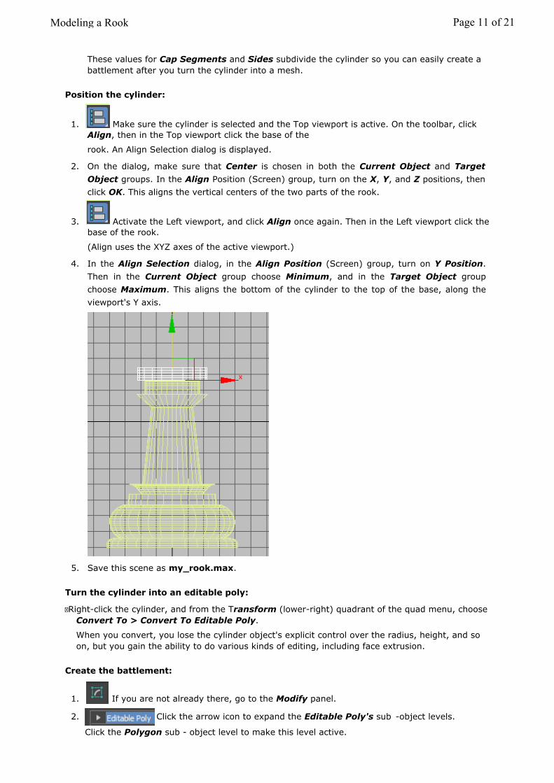
These values for Cap Segments and Sides subdivide the cylinder so you can easily create a battlement after you turn the cylinder into a mesh.
Position the cylinder:
1. Make sure the cylinder is selected and the Top viewport is active. On the toolbar, clickAlign, then in the Top viewport click the base of the
rook. An Align Selection dialog is displayed.
2. On the dialog, make sure that Center is chosen in both the Current Object and TargetObject groups. In the Align Position (Screen) group, turn on the X, Y, and Z positions, thenclick OK. This aligns the vertical centers of the two parts of the rook.
3. Activate the Left viewport, and click Align once again. Then in the Left viewport click thebase of the rook.
(Align uses the XYZ axes of the active viewport.)
4. In the Align Selection dialog, in the Align Position (Screen) group, turn on Y Position.Then in the Current Object group choose Minimum, and in the Target Object groupchoose Maximum. This aligns the bottom of the cylinder to the top of the base, along theviewport's Y axis.
5. Save this scene as my_rook.max.
Turn the cylinder into an editable poly:
� Right-click the cylinder, and from the Transform (lower-right) quadrant of the quad menu, choose Convert To > Convert To Editable Poly.
When you convert, you lose the cylinder object's explicit control over the radius, height, and so on, but you gain the ability to do various kinds of editing, including face extrusion.
Create the battlement:
1. If you are not already there, go to the Modify panel.
2.
Modeling a Rook Page 11 of 21
Click the arrow icon to expand the Editable Poly's sub -object levels.
Click the Polygon sub - object level to make this level active.

3. On the Selection rollout, turn on Ignore Backfacing.If Ignore Backfacing is not turned on, you might select other faces inadvertently, and getsome weird-looking extrusions.
4. In the Top viewport, use CTRL plus Select to select polygons around the rim of thecylinder. Select them in groups of three, leaving out every fourth polygon. You should wind up with five groups of three polygons selected.
Edge polygons selected to form the base of a battlement
5. On the Edit Geometry rollout, set Extrude to 8.0.
The faces are extruded and form the rook's battlement.
The battlement is formed of extruded faces.
6. Click Editable Poly in the modifier stack display to exit the Polygon sub -object level.
7. In the name field, rename the cylinder Rook Top.
Combine the two pieces of the rook:
Modeling a Rook Page 12 of 21

1. Go to the Create panel, Geometry section. Choose Compound Objects from the drop-down list.
2. Make sure the Rook Top object is selected.
3. Click Boolean.The Boolean compound object is a way to combine two objects into one. The twocomponents of the boolean are called operands.
4. On the Pick Boolean rollout, click Add Operands, and then pick the Rook Base
object. The base disappears!
Subtraction is the default Boolean operation. In this case, it is not what you want.
5. On the Parameters rollout, in the Operation group, change the type of operationfrom Subtraction (A-B) to Union.
Tip: The “Boolean” topic in the user's reference has guidelines for Boolean modeling. You should refer to these guidelines before you use Boolean yourself, to get the best results from this object type.
Consolidate your work:
1. Select the Boolean object that combines the base and top of the rook.
2. Go to the Modify panel, and in the Name field, rename the object Rook.
3. Right-click the rook object, and from the Transform (lower-right) quadrant of the quadmenu, chose Convert To > Convert To Editable Poly.
Compound objects such as Boolean and modifiers such as Lathe add complexity to yourscene, and consume system resources. Once geometry has the form you want, converting it toan editable poly can save system resources and make the scene more efficient.
Incidentally, the reason we did not convert the pawn to an editable mesh, was that we used aportion of the pawn's outline curve to create the base for the rook and other chessmen.
Modeling a Rook Page 13 of 21

4. Choose File > Save.
Summary
In this tutorial you learned to create new geometry using face extrusion, and to use the align tool to align objects. You also learned to add objects together using Boolean compound objects.
Next
Modeling a Bishop
Modeling a Rook Page 14 of 21

Tutorial
Modeling a Bishop In this lesson you will model a bishop for the chess set. As with the rook, the base of the bishop has already been created. You will add the “miter” on top of the bishop.
Features and techniques covered in this lesson:
� Using “soft selection” to create a free-form shape.
� Using Lock Selection to transform only what you want to.
� Using Boolean to subtract (instead of add) geometry.
Skill Level: Beginner
Time to complete: 15 minutes
Set up the lesson:
� Open the file bishop_base.max.
This file contains the base of the bishop.
Create a sphere:
The top of the bishop begins as a sphere.
1. Go to the Create panel and click Geometry. Make sure Standard Primitives is chosen in the drop-down list, and click Sphere.
2. In the Top viewport, drag from the center out to create a sphere. On the Parametersrollout, set its Radius to 18.0.
Position the sphere:
1. Make sure the sphere is selected and the Top viewport is active. On the toolbar, clickAlign. Then in the Top viewport, click the base of the
bishop. An Align Selection dialog is displayed.
2. On the dialog, make sure Center is chosen in both the Current Object and Target Object
Modeling a Bishop Page 15 of 21

groups. In the Align Position (Screen) group, turn on the X, Y, and Z positions, then click
OK. This aligns the vertical centers of the two parts of the bishop.
3. On the status bar, click to turn on Lock Selection.You are going to move the sphere, and this prevents you from accidentally moving the base instead.Tip: SPACEBAR is the keyboard shortcut for Lock Selection.
4. In the Left viewport, move the sphere vertically. Leave part of it sunk into the top of thebase.
5. Turn off Lock Selection.
6. Save this scene as my_bishop.max.
Turn the sphere into an editable mesh:
� Right-click the sphere, and from the Transform (lower-right) quadrant of the quad menu, choose Convert To > Convert To Editable Mesh.
Use soft selection to stretch the mesh:
1. If you are not already there, go to the Modify panel.
2. In the Left viewport, region zoom in on the sphere at the top of the bishop. Leave a bit ofspace above for it to grow.
3. In the modifier stack display, click the arrow icon to expand the Editable
Poly's sub -object levels. Click the Vertex sub - object level to make this level active.
Modeling a Bishop Page 16 of 21

4. In the Left viewport, drag a box to select the top two rows of vertices.
5. Go to the Soft Selection rollout, and turn on Use Soft Selection.
Soft selection provides a sort of gravity field: when soft selection is on and you move sub-objects, they drag other sub-objects along with them. Sub-objects affected by soft selection areindicated by how “hot” their color appears in viewports. The Falloff value controls the size of theaffected area.
6. Increase the Falloff to about 28.0, so soft selection will affect the sphere's upper vertices,but not its lower ones.
Vertices above the arrow are affected by soft selection. Vertices below it, shown in blue, are not.
7. Turn on Select and Move, and move the selected vertices vertically about 8 units. (Youcan see the amount of units displayed in the Y field of the XYZ spinners on the status bar, below the viewports.)
Modeling a Bishop Page 17 of 21

Note: You can use real-world units such as inches and feet, or meters if you like. In this tutorial you are using standard generic units which have no corresponding value in the real world.
With soft selection, other vertices trail after the selected ones, creating a characteristic egg-like shape for the top of the bishop.
8. In the modifier stack display, click Editable Mesh to turn off the Vertex sub-object level.
Create the knob at the very top:
These steps are a miniature version of creating the main top piece.
1. Go to the Create panel and click Geometry. Make sure Standard Primitives is chosen in the drop-down list. Click Sphere.
2. In the Top viewport, drag to create another sphere. Set its Radius to 5.0.
3. With the sphere selected and the Top viewport active, click Align. Then in the Topviewport, click the base of the bishop.
An Align Selection dialog is displayed.
4. On the dialog, in the Align Position (Screen) group, turn on Z position, then click
OK. This aligns the knob to the rest of the bishop.
5. On the status bar, click to turn on Lock Selection.
6. Activate the Left viewport, and then click Zoom Extents.
The Zoom Extents button is one of the viewport navigation buttons in the lower-right corner of the 3ds max window.
7. In the Left viewport, move the sphere vertically so it caps the chess piece.
Modeling a Bishop Page 18 of 21
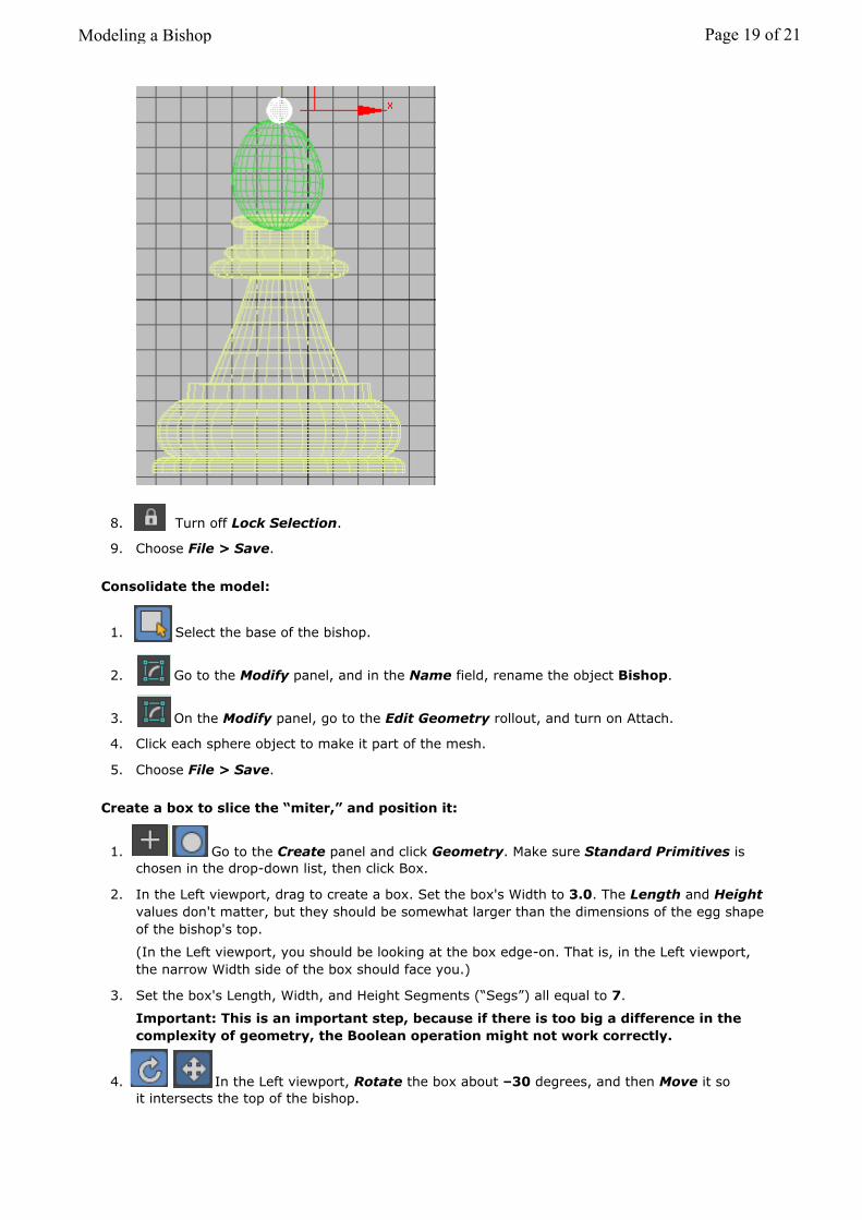
8. Turn off Lock Selection.
9. Choose File > Save.
Consolidate the model:
1. Select the base of the bishop.
2. Go to the Modify panel, and in the Name field, rename the object Bishop.
3. On the Modify panel, go to the Edit Geometry rollout, and turn on Attach.
4. Click each sphere object to make it part of the mesh.
5. Choose File > Save.
Create a box to slice the “miter,” and position it:
1. Go to the Create panel and click Geometry. Make sure Standard Primitives is chosen in the drop-down list, then click Box.
2. In the Left viewport, drag to create a box. Set the box's Width to 3.0. The Length and Heightvalues don't matter, but they should be somewhat larger than the dimensions of the egg shapeof the bishop's top.
(In the Left viewport, you should be looking at the box edge-on. That is, in the Left viewport,the narrow Width side of the box should face you.)
3. Set the box's Length, Width, and Height Segments (“Segs”) all equal to 7.
Important: This is an important step, because if there is too big a difference in thecomplexity of geometry, the Boolean operation might not work correctly.
4. In the Left viewport, Rotate the box about –30 degrees, and then Move it so it intersects the top of the bishop.
Modeling a Bishop Page 19 of 21
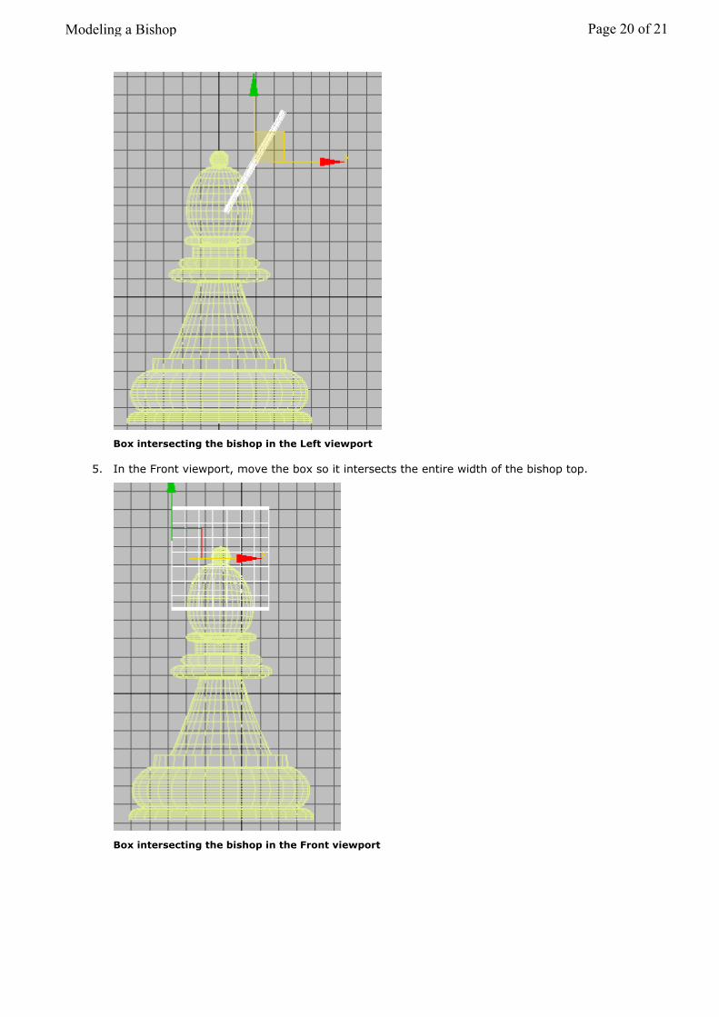
Box intersecting the bishop in the Left viewport
5. In the Front viewport, move the box so it intersects the entire width of the bishop top.
Box intersecting the bishop in the Front viewport
Modeling a Bishop Page 20 of 21
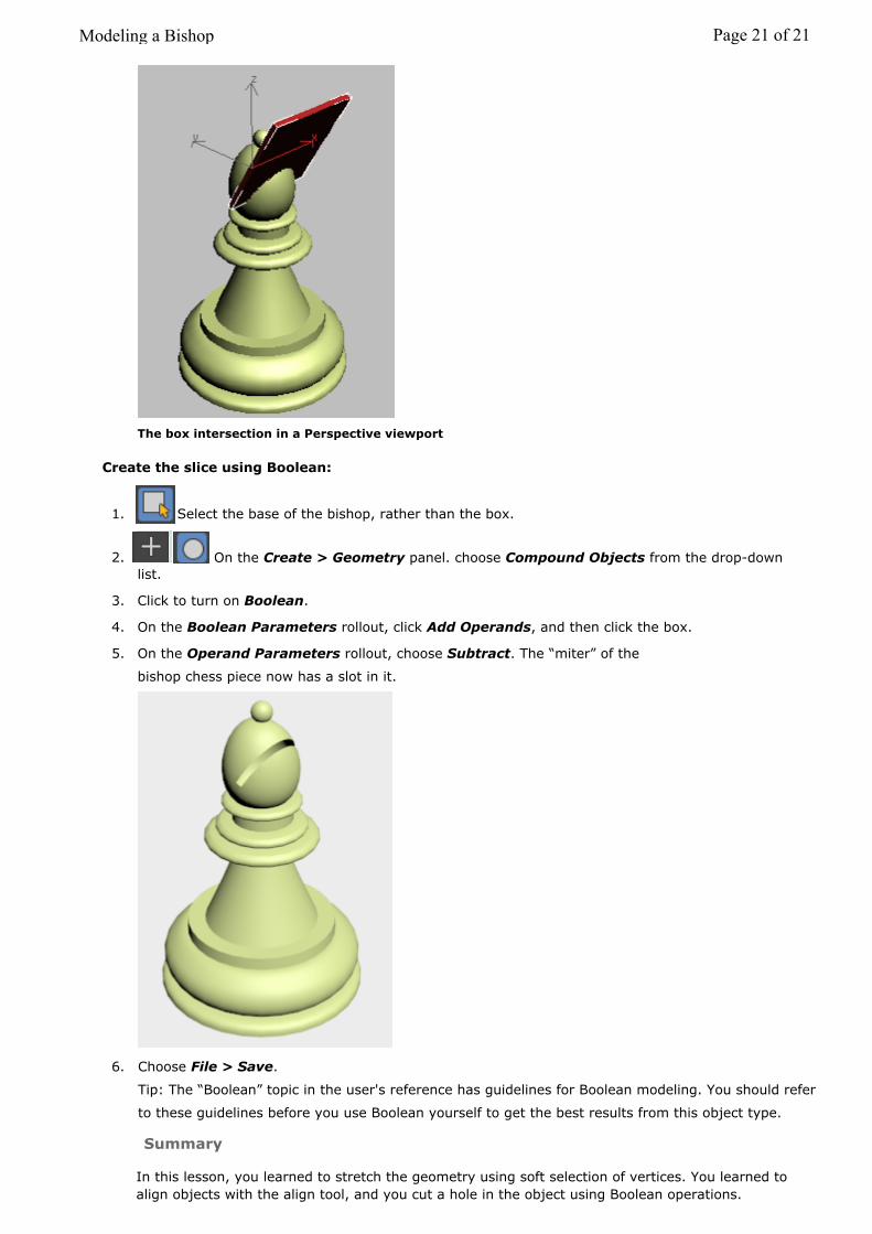
The box intersection in a Perspective viewport
Create the slice using Boolean:
1. Select the base of the bishop, rather than the box.
2. On the Create > Geometry panel. choose Compound Objects from the drop-downlist.
3. Click to turn on Boolean.
4. On the Boolean Parameters rollout, click Add Operands, and then click the box.
5. On the Operand Parameters rollout, choose Subtract. The “miter” of the
bishop chess piece now has a slot in it.
6. Choose File > Save.
Tip: The “Boolean” topic in the user's reference has guidelines for Boolean modeling. You should refer
to these guidelines before you use Boolean yourself to get the best results from this object type.
Modeling a Bishop Page 21 of 21
Summary
In this lesson, you learned to stretch the geometry using soft selection of vertices. You learned to align objects with the align tool, and you cut a hole in the object using Boolean operations.