414sdownload.tek.com/manual/414s_revb(model414s).pdf · 10.9 0.15 10.6 0.13 10-7 0.09 10 -6 0.05...
TRANSCRIPT

INSTRUCTION MANUAL
M o d e l 414s
P i c o a m m e t e r
COPYRIGHT 1977, K E I T H L E Y INSTRUMENTS, INC.
P R I N T E D MAY 1 9 7 8 , CLEVELAND, O H I O , U. S . A.

CONTENTS MODEL 414s
CONTENTS
1.
2.
3 .
4 .
5.
6.
7.
ii 0675

MODEL 414s
ILLUSTRATIONS
ILLUSTRATIONS
F i g . No. T i t l e Page
3
3
5
6
11
14
15
25
25
0675 iii
SPECIFICATIONS MODEL 414s
SPECIFICATIONS
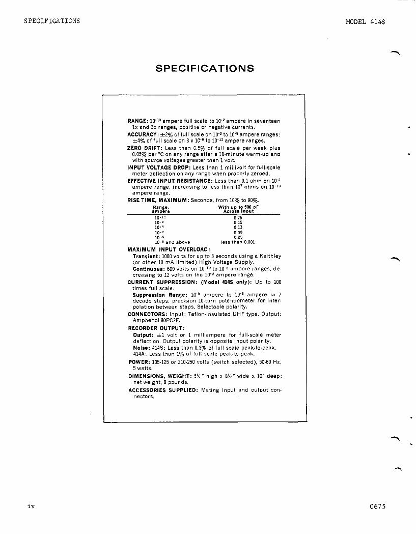
RANGE: 10-lo ampere fu l l scale to ampere i n seventeen l x and 3x ranges, positive or negative currents.
ACCURACY: &2% of fu l l scale on to ampere ranges: j=4% of fu l l scale on 3 x 10⁻⁹ to 10-10 ampere ranges.
ZERO DRIFT: Less than 0.5% of fu l l scale per week plus 0.05% per “ C on any range after a 10-minute warm-up and with source voltages greater than 1 volt.
INPUT VOLTAGE DROP: Less than 1 mi l l ivol t for full-scale meter deflection on any range when properly zeroed.
EFFECTIVE INPUT RESISTANCE: Less than 0.1 ohm on lom2 ampere range, increasing to less than lo7 ohms on 10’lo ampere range,
Range, atnoere Across Innut
RISE TIME, MAXIMUM: Seconds, f rom 10% to 90%. With up to 500 pF
10.10 0.75 10.9 0.15 10.6 0.13 10-7 0.09 10 - 6 0.05
and above less than 0.001 MAXIMUM INPUT OVERLOAD:
Transient: 1000 volts for u p to 3 seconds using a Keithley (or other 10 rnA l im i ted) High Voltage Supply. Continuous: 600 volts on 10-lo to 10-6 ampere ranges, de- creasing to 12 volts on the ampere range.
CURRENT SUPPRESSION: (Model 414s only): U p t o 100 t imes fu l l scale. Suppression Range: ampere t o ampere in 7 decade steps, precision 10-turn potentiometer for inter- polation between steps. Selectable polarity.
CONNECTORS: Inpu t : Teflon-insulated UHF type. Output: Amphenol8OPC2F.
RECORDER OUTPUT: Output: fl volt or 1 mi l l iampere for full-scale meter deflection. Output polarity i s opposite input polarity. Noise: 414s: Less than 0.3% of fu l l scale peak-to-peak. 414A: Less than 1% of fu l l scale peak-to-peak.
POWER: 105-125 or 210-250 volts (switch selected), 50-60 Hz, 5 watts.
DIMENSIONS, WEIGHT: 5 % “ high x 8%” wide x 10” deep; net weight, 8 pounds.
ACCESSORIES SUPPLIED: Mat ing input and output con- nectors.
iv
1 c
0675

MODEL 414s GENERAL DESCRIPTION
SECTION 1. GENERAL DESCRIPTION
1-1. GENERAL.
a. The K e i t h l e y Model 414s i s a comple t e ly s o l i d - s ta te pcioammeter which measures c u r r e n t s o v e r 1 7 r anges from t o 10-lo ampere f u l l s c a l e . Accuracy is 5 2 % of f u l l scale on t h e t o 10-8 ampere r a n g e s and 24% of f u l l scale o n t h e 3 x 10⁻⁹ t o 10-10 ampere r anges .
b . The Picoammeter employs matched MOS FET t r a n s i s - t o r s i n t h e i n p u t fo l lowed by a d i f f e r e n t i a l a m p l i f i e r s t a g e , a t r a n s i s t o r d r i v e r and a t r a n s i s t o r o u t p u t s t a g e . Nega t ive f eedback i s used f o r s t a b i l i t y and accu racy .
1- 2 . FEATURES.
a. The t i m e and t e m p e r a t u r e s t a b i l i t y of t h e 4145 Picoammeter i s unmatched by any o t h e r i n e x p e n s i v e p i co - ammeter. The Model 414s will o p e r a t e f o r days w i t h o u t r e q u i r i n g r e z e r o i n g . Zero d r i f t w i t h time i s less t h a n 0.5% of f u l l s c a l e p e r week. Temperature d r i f t i s e q u a l l y small - a change o f 10°C a f f e c t s t h e r e a d i n g less t h a n 0.5% of f u l l s c a l e on t h e most s e n s i t i v e
P
P
?-
b . A un ique c i r c u i t p r o v i d e s complete ove r load pro- t e c t i o n f o r Model 414s w i t h o u t compromising t h e out- s t a n d i n g f e a t u r e s of t h e MOS FET i n p u t . The Picoam- meter w i l l w i t h s t a n d t r a n s i e n t o v e r l o a d s up t o 1000 v o l t s w i t h o u t damage, and ove r load r ecove ry is almost i n s t a n t a n e o u s .
c. F a s t warm-up is a n i n h e r e n t c h a r a c t e r i s t i c of t h e Picoammeter. It can b e used almost immediately on i t s most s e n s i t i v e r a n g e . For maximum s t a b i l i t y , how- e v e r , abou t 10 minu tes warm-up time s h o u l d b e al lowed.
d . One v o l t o r 1 m i l l i a m p e r e a t f u l l - s c a l e d e f l e c - t i o n on a l l r a n g e s i s p rov ided t o d r i v e c h a r t r eco rd - ers . The 1 m i l l i a m p e r e r e c o r d e r o u t p u t w i l l d r i v e t h e K e i t h l e y 370 Recorder d i r e c t l y . r e c o r d e r s a r e u s e d , t h e o u t p u t v o l t a g e c a n b e conven- i e n t l y d i v i d e d by a s h u n t r e s i s t o r and a d j u s t e d f o r f u l l s c a l e w i t h t h e r e a r p a n e l C a l i b r a t i o n p o t e n t i o - meter.
When p o t e n t i o m e t r i c
0272 1

OPERATION
F u n c t i o n a l D e s c r i p t i o n
MODEL 414s
P a r .
TABLE 2. F r o n t P a n e l C o n t r o l s
Con t r o l
RANGE Switch
METER Switch
ZERO A D J . C o n t r o l
P i l o t L i g h t
SUPPRESSION, MAX AMPERES Switch
SUPPRESSION, FINE and P o l a r i t y Switch
Con t r o 1
INPUT R e c e p t a c l e
OUTPUT R e c e p t a c l e
1 MA - I V Switch
1 MA CAL C o n t r o l
117-234 V Switch
Fuse
S e l e c t s f u l l - s c a l e c u r r e n t r a n g e i n s t r u m e n t i s t o measure.
Turns i n s t r u m e n t on; s e l e c t s meter p o l a r i t y ; checks i n s t r u m e n t z e r o .
Ze roes meter on any r ange .
2-2
2-2
2-2
I --- Glows t o i n d i c a t e i n s t r u m e n t i s on.
S e l e c t s s u p p r e s s i o n c u r r e n t magni tude and t u r n s sup- p r e s s i o n c u r r e n t o f f .
C o n c e n t r i c s w i t c h e s : one d e t e r m i n e s p o l a r i t y of sup- p r e s s i o n c u r r e n t , t h e o t h e r (FINE) v a r i e s t h e s u p p r e s s i o n from z e r o t o maximum se t by t h e MAX AMPERES Swi t ch .
2-2
2-4
TABLE 3. Rear P a n e l C o n t r o l s
~~
F u n c t i o n a l D e s c r i p t i o n
Connects i n p u t t o s o u r c e . R e c e p t a c l e i s a T e f l o n i n s u l a t e d UHF Connector .
Connects o u t p u t t o m o n i t o r i n g d e v i c e .
S e l e c t s o u t p u t of i n s t r u m e n t : 1 m i l l i a m p e r e o r 1 v o l t .
A d j u s t s o u t p u t f rom 0 .95 t o 1 . 0 5 mA.
S e t s i n s t r u m e n t f o r 117 o r 234 v o l t a c power l i n e .
3AG Slow-Blow. 1 1 7 v o l t - .125 A; 234 v o l t - .062 A .
P a r .
2-1
2-5
2-5
2-5
2-2
2-6
1
2 0272

MODEL 414s GENERAL DESCRIPTION
6
r
f
3
I- I I I I I -
RANGE
S 103 -WITCH
POWER ON METER ZERO ADJ SUPPRESSION SUPPRESSION INDICATOR SWITCH CONTROL POLARITY FINE MAX AMPERES DS201 S l o l R131 CONTROL CONTROL SWITCH S102
S 104 R108
FIGURE 1. F r o n t Panel C o n t r o l s .
INPUT 5102
w
CA1 IMA-IY / OUTPUT IMA
1 M A - l V T W I T C H
S 105
A U T P U T 5 1 0 3
1 1 7 -23 4V -ELECTOR
s 2 0 1
I FIGURE 2 . Rear Panel C o n t r o l s .
0272 3

OPERATION
SECTION 2. OPERATION
MODEL 414s PICOAMPETER
2 - 1 . INPUT CONNECTIONS. Use t h e fo l lowing p r e c a u t i o n s 1. When t h e RANGE Switch i s s e t t o 1 0 , 1, 0 . 1 , when us ing t h e Picoammeter on t h e more s e n s i t i v e ranges . e t c . p o s i t i o n s , use t h e upper meter s c a l e . F u l l
s c a l e c u r r e n t range i s equal t o t h e RAEiGE SiJitch s e t - t i n g .
a . The INPUT Receptacle of t h e Model 414s i s a Tef- l o n - i n s u l a t e d UHF connec tor . The c e n t e r te rmina l i s t h e high impedance t e r m i n a l , and t h e o u t e r s h i e l d i s case ground.
b. C a r e f u l l y s h i e l d t h e i n p u t connec t ion and t h e c u r - r e n t source be ing measured, s i n c e power l i n e f r e q u e n c i e s a r e w e l l w i t h i n t h e pass band of t h e Picoammeter on a l l ranges. Unless s h i e l d i n g i s thorough, pickup may cause d e f i n i t e meter d i s t u r b a n c e s .
c . Use high r e s i s t a n c e , low-loss m a t e r i a l s - such a s polye thylene , po lys tyrene o r Tef lon - f o r i n s u l a - t i o n . The i n s u l a t i o n r e s i s t a n c e of t e s t l e a d s and f i x - t u r e s should be s e v e r a l o r d e r s of magnitude h i g h e r than the source r e s i s t a n c e . Excessive leakage w i l l reduce accuracy. Any c o a x i a l c a b l e used should be a low- n o i s e type which employs a g r a p h i t e c o a t i n g between t h e d i e l e c t r i c and t h e surrounding s h i e l d b r a i d .
d . Any change i n t h e c a p a c i t a n c e of t h e measuring c i r c u i t t o ground w i l l cause d i s t u r b a n c e s i n t h e read- i n g , e s p e c i a l l y on t h e more s e n s i t i v e ranges. Make t h e measuring s e t u p a s r i g i d a s p o s s i b l e , and t i e down con- nec t ing c a b l e s t o prevent t h e i r movement. I f a c o n t i n - uous v i b r a t i o n i s p r e s e n t , i t may appear a t t h e o u t p u t a s a s i n u s o i d a l s i g n a l and o t h e r p r e c a u t i o n s may be necessary t o i s o l a t e t h e ins t rument and t h e connec t ing c a b l e from t h e v i b r a t i o n .
NOTE
Keep t h e s h i e l d cap on t h e INPUT Receptacle when t h e Picoammeter i s n o t i n a c i r c u i t .
2 -2 . OPERATING PROCEDURES.
a . Check t h e f u s e and t h e 117-234 V Switch f o r t h e proper l i n e v o l t a g e .
b . Connect t h e power cord t o t h e power source .
c . S e t t h e RANGE Switch t o l o m 2 ampere, t h e METER S A t c h t o ( + ) . Within seconds t h e meter needle should read zero . Zero t h e meter w i t h t h e ZERO A D J . Cont ro l . A f t e r a few moments i n c r e a s e t h e c u r r e n t s e n s i t i v i t y b
ampere range. Continue zero ing wi th t h e ZERO A D J Con- t r o l . The instrument i s now ready t o u s e .
advancing t h e RANGE Switch i n decade s t e p s t o t h e 10- 15
2 . When t h e RANGE Switch i s s e t t o 3 , 0 . 3 , 0 . 0 3 , e t c . p o s i t i o n s , use t h e lower meter s c a l e . F u l l s c a l e c u r r e n t range i s equal t o t h e RANGE Switch s e t t i n g .
2-3. MEASUREMENT CONSIDERATIONS,
a . The Picoammeter employs t h e f a s t method of c u r - r e n t measurement - t h e measuring r e s i s t o r i s between t h e a m p l i f i e r input and o u t p u t i n t h e feedback loop. This method l a r g e l y n e u t r a l i z e s t h e e f f e c t of input c a p a c i t y and g r e a t l y i n c r e a s e s t h e response speed. Also, t h e i n p u t v o l t a g e drop i s reduced t o a maximum of one m i l l i v o l t on any range.
b . Rise time v a r i e s wi th t h e c u r r e n t range and the i n p u t c a p a c i t y ( s e e s p e c i f i c a t i o n s , Table 1). The r i s e time, though, i s not a f f e c t e d wi th up t o 500 p icofarads a c r o s s t h e i n p u t ; however, i t i s b e t t e r t o p lace t h e Picoammeter n e a r e r t h e c u r r e n t source than t o the d a t a reading ins t rument . Transmi t t ing t h e input s i g n a l through long c a b l e s - with g r e a t e r than 500 p icofarads of c a p a c i t a n c e - w i l l i n c r e a s e response time and meter n o i s e .
c . The i n t e r n a l r e s i s t a n c e of t h e unknown source should not be l e s s than t h e r e c i p r o c a l of t h e c u r r e n t range be ing u s e d , o therwise t h e zero s t a b i l i t y w i l l be a f f e c t e d . The instrument w i l l s t i l l be o p e r a b l e , how- e v e r , bu t t h e s t a b i l i t y w i l l be degraded by t h e amount given by equat ion 1.
S t a b i l i t y = 0.5%/week x (Rs + Rf)/Rs Equat ion 1.
where R f i s t h e feedback r e s i s t a n c e i n ohms; R, i s t h e source r e s i s t a n c e i n ohms.
For example, i f t h e source t o be measured has a r e s i s - t ance of 105 ohms and t h e c u r r e n t i s lom6 then the feed- back r e s i s t o r w i l l be 106 ohms. h i s means t h a t the g a i n of t h e Picoammeter i s 106/10T = 10. Then t h e zero s t a b i l i t y of .5%/week w i l l be .5% X 10 = 5%/week, and t h e o f f s e t due t o temperature w i l l be .05% X lo*= .5%/'C. This i s t h e reason t h a t i t i s advantageous t o have t h e source r e s i s t a n c e a t l e a s t equal t o t h e feed- back r e s i s t o r .
d . Overload P r o t e c t i o n . A unique c i r c u i t provides complete overload p r o t e c t i o n f o r t h e Model 414s with- o u t compromising t h e f e a t u r e s of t h e MOS E'ET i n p u t . Recovery i s ins tan taneous f o r most over loads . -
.
d . I f long term measurements a r e t o be made, a l low 1. A t t h e ampere range and below t h e Picoam- t h e instrument t o warm up f o r a t l e a s t 10 minutes . meter can wi ths tand overloads of up t o 1000 v o l t s
f o r 3 seconds and cont inuous over loads of up t o 600 e . At tach t h e c u r r e n t source t o t h e INPUT Receptac le v o l t s wi thout damage. ..4
and t u r n t h e METER Switch t o t h e p o l a r i t y of t h e i n p u t s i g n a l , + o r -. I n c r e a s e s e n s i t i v i t y w i t h t h e RANGE 2 . Above amperes, t h e max. cont inuous overload Switch u n t i l t h e g r e a t e s t on s c a l e d e f l e c t i o n i s ach ieved , i s a f u n c t i o n of r a t e d power d i s s a p a t i o n i n t h e r e s i s t o r .
4 02 72

MODEL 414s OPERATION
f- TABLE 4. Allowable Overloads on Ranges Above Ampere.
Max. Cont inuous Max. Cont inuous Range Vo l t age Overload Cur ren t Overload
10-5 A 10-4 A 10-3 A
A
300 V 120 v
30 V 12 v
1 m A 4mA
1 0 mA 40 mA
1 I OUTPUT
5103
RECORDER OUTPUT
3. For maximum p r o t e c t i o n , u s e a K e i t h l e y Model L I
240A Vol t age Supply, o r some o t h e r 10 m i l l i a m p e r e FIGURE 3. D i v i d e r C i r c u i t s Across Picoammeter Output c u r r e n t l i m i t e d s u p p l y , i n combinat ion w i t h t h e f o r D r i v i n g 50 and 1 0 0 - M i l l i v o l t Recorde r s . Picoammeter.
2-4. RECORDER OUTPUTS.
a . For r e c o r d i n g w i t h t h e Model 414S, u s e t h e Kei th- l e y Model 370 Recorder f o r ease, economy, v e r s a t i l i t y and performance. The Model 370 i s a pen r e c o r d e r w i t h 10 c h a r t speeds and 1% l i n e a r i t y . The Model 3 7 0 ' s i n - p u t c a b l e h a s a connec to r which mates d i r e c t l y w i t h t h e OUTPUT Connector on t h e Picoammeter; t h i s a v o i d s i n t e r f a c e problems o f t e n encoun te red between a measur- i n g i n s t r u m e n t and a r e c o r d e r . The Picoammeter o u t p u t , when se t t o t h e 1 mA p o s i t i o n , w i l l d r i v e t h e 370; no p r e a m p l i f i e r i s needed. No s p e c i a l w i r i n g i s r e q u i r e d .
b . O the r r e c o r d e r s , o s c i l l o s c o p e s and similar in - s t r u m e n t s can b e used w i t h t h e Model 414s. The Pico- ammeter has two o u t p u t s , 51 v o l t and 21 m i l l i a m p e r e , t o ampl i fy s i g n a l s f o r r e c o r d e r s , o s c i l l o s c o p e s and similar i n s t r u m e n t s . These can b e used on a l l r a n g e s .
c . 1-Volt Output . Connect o s c i l l o s c o p e s and pen r e c o r d e r a m p l i f i e r s t o t h e OUTPUT Recep tac l e . P i n no. 1 i s t h e h i g h t e r m i n a l and p i n no. 2 i s ground. S e t t h e 1 mA - 1 V Switch t o 1 V . The Picoammeter o u t p u t i s now 21 v o l t f o r f u l l s c a l e meter d e f l e c t i o n on any r ange . I n t e r n a l r e s i s t a n c e i s approx ima te ly 1 ki lohm. Noise i s less t h a n 1% peak-to-peak of f u l l s c a l e . The METER Switch does n o t r e v e r s e t h e o u t p u t p o l a r i t y . Output p o l a r i t y i s always o p p o s i t e i n p u t p o l a r i t y .
d. 1-Mil l iampere Output . Connect 1 -mi l l i ampere i n s t r u m e n t s t o t h e OUTPUT Recep tac l e . P i n no. 1 is t h e h i g h t e r m i n a l . S e t t h e 1 mA - 1 V Switch t o 1 mA. The o u t p u t i s approx ima te ly 1 m i l l i a m p e r e f o r f u l l - s c a l e meter d e f l e c t i o n on any r ange . Fo r exact o u t p u t , app ly a known f u l l s c a l e s i g n a l t o t h e Picoammeter and a d j u s t t h e 1 mA CAL C o n t r o l u n t i l t h e r e c o r d e r r e a d s f u l l s c a l e , Check t h e r e c o r d e r and meter z e r o and r e p e a t ad jus tmen t i f n e c e s s a r y . The METER Switch does n o t reverse t h e o u t p u t p o l a r i t y which i s always oppo-
r
r s i t e i n p u t p o l a r i t y .
e. For s e r v o r e b a l a n c e r e c o r d e r s , u s e a d i v i d e r a c r o s s t h e Picoammeter OUTPUT Recep tac l e . See F i g u r e 3. S e t t h e OUTPUT Switch t o 1 mA. Use t h e 1 mA CAL
f l e c t i o n s . Opera t ion i s t h e same as f o r c u r r e n t o u t p u t s . sc" C o n t r o l t o t r i m t h e o u t p u t f o r f u l l - s c a l e r e c o r d e r de-
2-5., 234-VOLT OPERATION. The i n s t r u m e n t i s shipped f o r u s e w i t h a 117-vo l t power s o u r c e u n l e s s o the rwise o r d e r e d . To c o n v e r t t h e Picoammeter f o r 234-volt s o u r c e s , u s e a s c r e w d r i v e r t o change t h e s l i d e swi t ch on t h e back p a n e l t o t h e 234-volt p o s i t i o n . Change' t h e f u s e from 0.125 ampere t o ,062 ampere. No o t h e r ad jus tmen t i s n e c e s s a r y . To s w i t c h from 234 t o 117- v o l t o p e r a t i o n , r e v e r s e t h e p rocedures .
2-6. SUPPRESSION CURRENT OPERATION. The Model 414s p r o v i d e s up t o 100 t imes c u r r e n t s u p p r e s s i o n over a r ange of loe3 t o lom9 ampere. By s u p p r e s s i n g back- ground c u r r e n t s , v a r i a t i o n s a s small as 1% i n a l a r g e r s i g n a l can b e d i s p l a y e d f u l l s c a l e . C u r r e n t s of e i t h e r p o l a r i t y may b e s u p p r e s s e d .
a . Suppres s ion i s ach ieved by a p p l y i n g a c u r r e n t of o p p o s i t e p o l a r i t y t o t h e i n p u t c u r r e n t a t t h e i n p u t of t h e Picoammeter. Th i s s u p p r e s s i o n c u r r e n t i s ob ta ined from w e l l r e g u l a t e d 212 v o l t s u p p l i e s i n con junc t ion w i t h r e s i s t o r s .
b . Use t h e s u p p r e s s i o n c i r c u i t as f o l l o w s :
1. S e t t h e SUPPRESSION, P o l a r i t y C o n t r o l t o + or -, as n e c e s s a r y .
2. S e t t h e SUPPRESSION, MAX AMPERES Switch t o t h e same s e n s i t i v i t y as t h e RANGE Switch s e t t i n g . Adjust t h e 10 - tu rn FINE C o n t r o l f o r a z e r o r e a d i n g on t h e meter. I n c r e a s e t h e s e n s i t i v i t y of t h e RANGE Switch one decade . A d j u s t t h e FINE C o n t r o l f o r a z e r o read- i n g . T h i s i s t e n times c u r r e n t s u p p r e s s i o n . To ob- t a in 100 t i m e s s u p p r e s s i o n , i n c r e a s e t h e s e n s i t i v i t y of t h e RANGE Switch one more decade and z e r o t h e meter. I n t h i s mode t h e Model 414s is a b l e t o d e t e c * f l u c t u a t i o n s of 1% of f u l l s c a l e of t h e Suppres s ion c u r r e n t .
c. When u s i n g 100 times f u l l s c a l e s u p p r e s s i o n t h e r e s i s t o r used i n t h e s u p p r e s s i o n c i r c u i t w i l l b e one- t e n t h t h e v a l u e of t h e c u r r e n t measuring r e s i s t o r . I n t h i s mode t h e z e r o d r i f t and t empera tu re d r i f t w i l l b e approx ima te ly t e n times g r e a t e r t h a n normal. (See t h e d i s c u s s i o n i n p a r a g r a p h 2-3c f o r e x p l a n a t i o n ) .
0272 5

C I R C U I T DESCRIPTION
SECTION 3. CIRCUIT DESCRIPTION
MODEL 414s
3-1. GENERAL. The Kei th ley Model 414s i s a l i n e a r d c a m p l i f i e r w i t h a f u l l s c a l e s e n s i t i v i t y of e i t h e r 1 o r 3 v o l t s . By us ing t h e f r o n t pane l c o n t r o l s , shunt re- s i s t o r s are s e l e c t e d t o make measurements over a t o t a l of 1 7 c u r r e n t ranges. (Refer t o schematic diagram 223943 f o r c i r c u i t d e s i g n a t i o n s . )
3-2. AMMETER OPERATION.
a. The a m p l i f i e r has matched i n s u l a t e d - g a t e f i e l d - e f f e c t i n p u t t r a n s i s t o r s followed by a d i f f e r e n t i a l t r a n s i s t o r s t a g e , a t r a n s i s t o r a m p l i f i e r and a t ran- s i s t o r output s t a g e . Figure 4 shows t h e s i m p l i f i e d c i r c u i t f o r t h e Picoammeter.
Rs
FIGURE 4. S impl i f ied Diagram f o r Ammeter C i r c u i t .
b . I f i t i s assumed t h a t t h e input v o l t a g e drop , e i n , i s n e g l i g i b l e , then a l l t h e i n p u t c u r r e n t , iin, flows through t h e measuring r e s i s t o r , R, , and
eo = -iin R,. Equat ion 2.
But t h e output v o l t a g e , eo, is a l s o equal t o t h e i n p u t vo l tage times t h e a m p l i f i e r ga in .
eo -A e i n . Equation 3.
Therefore , from equat ions 2 and 3 w e g e t
A e i n = iin R,. Equation 4.
From whence,
Equat ion 5 .
where e in/ i in is t h e e f f e c t i v e i n p u t r e s i s t a n c e .
Thus, t h e i n p u t v o l t a g e drop i s k e p t a t a small f r a c - t i o n , 1 / A , of t h e output v o l t a g e , and t h e e f f e c t i v e in- put r e s i s t a n c e i s 1 / A of t h e measuring r e s i s t o r .
3-3. AMMETER C I R C U I T .
a . Two balanced insu la ted-ga te f i e l d - e f f e c t t ran- s i s t o r s , Q l O l and 4102, are used f o r t h e a m p l i f i e r in- pu t . R e s i s t o r s R125 and R126 and c i r c u i t des igna t ion 21850B (see schematic) p r o t e c t t h e g a t e of t r a n s i s t o r Q l O l , t h e a c t i v e f i e l d - e f f e c t t r a n s i s t o r , from over- l o a d s . The g a t e of Q102 is re turned t o a m p l i f i e r ground.
b . Turning t h e METER Switch t o ZERO CK p o s i t i o n p l a c e s a s h o r t from t h e i n p u t t o the output and zeroes t h e ins t rument .
c . A d i f f e r e n t i a l a m p l i f i e r s t a g e , t r a n s i s t o r s Q103 and Q104, d r i v e s an a m p l i f i e r s t a g e , t r a n s i s t o r Q l O S , which i n t u r n d r i v e s t h e output emitter f o l l o w e r , t ran- s i s t o r 4106.
d . Two zero c o n t r o l s are used. The Coarse Zero Cont ro l , R128 v a r i e s t h e source v o l t a g e of t r a n s i s t o r Q l O l w i t h r e s p e c t t o t r a n s i s t o r 4102. The ZERO ADJ Cont ro l , R131, v a r i e s t h e d r a i n v o l t a g e of t r a n s i s t o r Q l O l w i t h r e s p e c t t o t r a n s i s t o r 4102.
e. The DC Bal Poten t iometer , R 1 2 7 , sets t h e d r a i n c u r r e n t through t r a n s i s t o r s Q l O l and 4102 by varying t h e source b i a s ,
f . The v o l t a g e drop a c r o s s R123 p l u s R124, o r R124 a l o n e , determines t h e f u l l s c a l e s e n s i t i v i t y of t h e a m p l i f i e r - e i t h e r 3 v o l t s from throu h 3 x and 3 x lom9 and 3 x 1O-lo o r 1 v o l t on l O - Q , 10-10 ranges . p u t causes a 1 mil l iampere c u r r e n t t o flow through R123 and R124. The meter i s connected a c r o s s the 3- v o l t ou tput . R e s i s t o r s R138 and R139 set t h e meter c u r r e n t .
and Applying a f u l l scale s i g n a l t o t h e in-
.
g. The f u l l s c a l e c u r r e n t s e n s i t i v i t y i s determined by t h e range r e s i s t o r s R109 through R122 i n combination w i t h r e s i s t o r s R123 and R124. The c u r r e n t measuring r e s i s t o r is connected i n t h e feedback loop. This con- f i g u r a t i o n i n c r e a s e s t h e response speed by minimizing t h e e f f e c t s of i n p u t capac i ty . It a l s o reduces the i n p u t v o l t a g e drop t o less than 1 m i l l i v o l t .
h . The 1 v o l t r e c o r d e r ou tput i s der ived from 1 mil l iampere f lowing through r e s i s t o r R143. mil l iampere output mode an e x t e r n a l load i s s u b s t i t u t e d f o r R143. Poten t iometer R141 v a r i e s t h e c u r r e n t t o the e x t e r n a l load.
I n t h e 1
c
3-4. POWER SUPPLIES. The Model 414s has p o s i t i v e and n e g a t i v e s u p p l i e s , which provide power t o t h e ampli- f i e r and output . ?
a. +25 and +12 v o l t supply. The power suppl ied from secondary of t ransformer T201 is r e c t i f i e d by diodes D201 and D203 and f i l t e r e d by c a p a c i t o r C201 t o provide +25 v o l t s f o r t h e output . Zener d iode , D205, i s used t o provide a r e g u l a t e d +11 v o l t s f o r t h e a m p l i f i e r .
b . -25 and -12 v o l t supply. This supply uses diodes D202 and D204, c a p a c i t o r C202 and Zener D206 t o per-
6
form t h e same f u n c t i o n s as t h e p o s i t i v e supply.
0272

MODEL 414s C I R C U I T DESCRIPTION
6 3-5. SUPPRESSION C I R C U I T . The s u p p r e s s i o n i s o b t a i n e d from two w e l l r e g u l a t e d s u p p l i e s i n c o n j u n c t i o n w i t h decade v a l u e s of r e s i s t o r s and a t e n - t u r n p o t e n t i o - meter. Suppres s ion i s o b t a i n e d by p l a c i n g one of va r - i o u s r e s i s t o r s between t h e i n p u t of t h e ammeter and a power supp ly . The magnitude of t h e s u p p r e s s i o n cur- r e n t i s determined by t h e s e t t i n g of t h e SUPPRESSION, FINE P o t e n t i o m e t e r , R108. Suppres s ion c u r r e n t p o l a r i t y i s determined by which power s u p p l y t h e p o t e n t i o m e t e r i s connected t o .
a. +12 v o l t Supply.
1. The secondary of t h e l i n e t r a n s f o r m e r , T201, i s r e c t i f i e d by d i o d e s D201 and D203 and f i l t e r e d by C201 and a p p l i e d t o t h e c o l l e c t o r o f t h e series p a s s t r a n s i s t o r , Q201. R e s i s t o r R202 and t h e zene r d i o d e , D205, form a b o o t s t r a p c i r c u i t t o s u p p l y s t a r t i n g c u r r e n t . The p o s i t i v e supp ly does n o t u s e a z e n e r d i r e c t l y f o r a r e f e r e n c e e l e m e n t , b u t u s e s t h e -12 v o l t supp ly as a r e f e r e n c e .
2. The b a s e of Q206, connected as one h a l f of a d i f f e r e n t i a l a m p l i f i e r , i s r e t u r n e d t o ground. The b a s e of t h e o t h e r t r a n s i s t o r , Q207, i s connected t o t h e j u n c t i o n of two e q u a l r e s i s t o r s , R211 and R212, which are connected between t h e o u t p u t s of t h e 5 s u p p l i e s . I f t h e f eedback t o t h e series p a s s t r a n - s i s t o r i s of t h e p r o p e r p h a s e , t h e n t h e b a s e of t r a n - s i s t o r 4207 must b e approx ima te ly z e r o v o l t s t o main- t a i n p rope r o p e r a t i n g c o n d i t i o n s . For t h i s t o b e r s o , t h e o u t p u t of t h e + s u p p l y must go t o t h e same magnitude of t h e n e g a t i v e s u p p l y (12 v o l t s ) .
3 . The c o l l e c t o r of Q206 i s a t t a c h e d t o t h e b a s e of 4204, one-half of t h e d i f f e r e n t i a l p a i r formed w i t h Q205. The b a s e of 4205 i s r e t u r n e d t o a re- f e r e n c e v o l t a g e a t t h e j u n c t i o n of t h e r e s i s t o r s R207 and R208 connected between +12 and ground.
4. The c o l l e c t o r of 4204 d r i v e s t h e b a s e of t h e D a r l i n g t o n a m p l i f i e r , 4202, which d r i v e s t h e b a s e of t h e series p a s s t r a n s i s t o r , 4201.
5 . T r a n s i s t o r Q203 a c t s as a n ove r load p r o t e c t i o n by s e n s i n g t h e v o l t a g e d rop a c r o s s r e s i s t o r R206. On ove r load t h e v o l t a g e d rop a c r o s s R206 causes 4203 t o t u r n on which clamps t h e b a s e of Q202 t o t h e out- p u t , t h u s l i m i t i n g t h e maximum c u r r e n t d r a i n .
b . -12 V o l t Supply.
1. The secondary of t r a n s f o r m e r T201 i s r e c t i f i e d by d i o d e s D202 and D204, f i l t e r e d by c a p a c i t o r C205 and a p p l i e d t o t h e c o l l e c t o r of t h e s e r i e s pas s t r an - s i s t o r , 4208. R e s i s t o r R213 and zene r d i o d e 0206 form a b o o t s t r a p c i r c u i t t o s u p p l y s t a r t i n g c u r r e n t .
2. The b a s e of Q212, one-half of a d i f f e r e n t i a l a m p l i f i e r , i s r e f e r e n c e d t o zene r d i o d e D208. The b a s e of 4213 i s connected t o t h e c e n t e r t a p of p o t e n t i o m e t e r R222 which sets t h e v a l u e of t h e out- p u t v o l t a g e .
3. The c o l l e c t o r of Q212 i s a t t a c h e d t o t h e b a s e of a m p l i f i e r 9211 which d r i v e s t h e b a s e of t h e D a r l i n g t o n a m p l i f i e r , 4209, which d r i v e s t h e b a s e of t h e series p a s s t r a n s i s t o r , Q208.
4 . T r a n s i s t o r Q210 a c t s a s an ove r load p r o t e c t i o n as d e s c r i b e d i n pa rag raph 5 above.
c. C u r r e n t Suppres s ion .
1. The P o t e n t i o m e t e r , R108, i s connected t o e i t h e r t h e + o r - s u p p l y by S104. The c e n t e r t a p of R108 i s a t t a c h e d t o one of t h e c u r r e n t suppres- s i o n r e s i s t o r s , R l O l through R107, s e l e c t e d by S102. The o t h e r end of t h e r e s i s t o r i s a t t a c h e d t o t h e i n p u t of t h e ammeter.
2. The magnitude of t h e s u p p r e s s i o n i s d e t e r - mined by t h e s e t t i n g of t h e p o t e n t i o m e t e r which v a r i e s t h e v o l t a g e t o t h e r e s i s t o r .
0272 7

SERVICING MODEL 414s
SECTION 4.
4-1. GENERAL. S e c t i o n 4 c o n t a i n s t h e maintenance and t roubleshoot ing procedures f o r t h e Model 414s Picoam- meter . Follow t h e s e procedures a s c l o s e l y a s p o s s i b l e t o main ta in t h e performance of t h e ins t rument .
4-2. SERVICING SCHEDULE, The v a l u e of t h e high-rnegohm r e s i s t o r s , R121 and R122, should be checked approximate- l y every s i x months f o r s p e c i f i e d accuracy . Except f o r t h i s t h e Model 414s r e q u i r e s no p e r i o d i c maintenance beyond t h e normal c a r e requi red of h i g h - q u a l i t y e l e c - t r o n i c equipment.
4-3. PARTS REPLACEMENT.
a . The Replaceable P a r t s L i s t i n S e c t i o n 7 . d e s c r i b e s the e l e c t r i c a l components of t h e Picoammeter. Replace components only as necessary . Use only r e l i a b l e r e - placements which meet t h e s p e c i f i c a t i o n s .
b. The MOS FET input t r a n s i s t o r s , Q l O l and Q 1 0 2 , a r e s p e c i a l l y s e l e c t e d and matched; order only a s a plug- i n u n i t , p a r t number 2 3 7 3 4 A , from K e i t h l e y I n s t r u m e n t s , I n c .
4-4. TROUBLESHOOTING.
a . The Procedures which fo l low g ive i n s t r u c t i o n s f o r r e p a i r i n g t r o u b l e s which might occur i n Model 414s. Use t h e procedures o u t l i n e d and use only s p e c i f i e d
SERVICING
replacement p a r t s . Table 5 l i s t s equipment recommen- ded f o r t r o u b l e s h o o t i n g . I f t h e t r o u b l e cannot be r e a d i l y l o c a t e d o r r e p a i r e d , c o n t a c t Kei th ley I n s t r u - ments , I n c . , o r i t s r e p r e s e n t a t i v e .
b . Table 6 c o n t a i n s t h e more common t r o u b l e s which might occur . I f t h e r e p a i r s i n d i c a t e d i n t h e t a b l e do not c l e a r up t h e t r o u b l e , f i n d t h e d i f f i c u l t y through a c i r c u i t - b y - c i r c u i t check , such a s given i n paragraph 4-5. Refer t o c i r c u i t d e s c r i p t i o n i n Sec- t i o n 3 t o f i n d t h e more c r i t i c a l components and t o determine t h e i r f u n c t i o n i n t h e c i r c u i t . The complete c i r c u i t schemat ic , 2 2 3 9 4 3 , i s i n Sec t ion 7 .
4-5 . PROCEDURES TO G U I D E TROUBLESHOOTING.
a . I f t h e ins t rument w i l l not o p e r a t e , check the power s u p p l i e s . The t y p i c a l v o l t a g e v a l u e s , given on t h e schemat ic , a r e re ferenced t o c h a s s i s ground. Zero t h e Model 414s meter and make measurements w i t h a Model 153.
b . A t t imes , t h e meter w i l l no t zero on any range wi th t h e METER Switch i n t h e ZERO CK p o s i t i o n . I f t h i s o c c u r s , a d j u s t t h e f r o n t panel ZERO ADJ Control o r , i f n e c e s s a r y , t h e Coarse Zero Poten t iometer , R128, l o c a t e d on t h e PC board. I f t h i s does n o t work, i n - s p e c t a l l PC boards f o r a p o s s i b l e break i n t h e t a p e s . I f t h e s e appear a l l r i g h t proceed wi th s t e p c .
TABLE 5. Equipment Recommended f o r Model 414s Troubleshoot ing and C a l i b r a t i o n . Use t h e s e ins t ruments o r t h e i r e q u i v a l e n t s . I
Ins t ruments use ~~
K e i t h l e y Model 163 D i g i t a l Voltmeter,. 20.1% of General c a l i b r a t i o n . reading , 10 megohm input r e s i s t a n c e .
Hewlett Packard 202A Funct ion Generator Rise time check.
Kei th ley Ins t ruments Model 153 Microvolt-Ammeter, General c i r c u i t checking. 10 pV t o 1000 V , 2 0 0 Mfl input r e s i s t a n c e , *l% accu- racy , f l o a t f500 v o l t s o f f ground.
Kei th ley Ins t ruments Model 261 Picoampere Source; Source t o c a l i b r a t e c u r r e n t . 10-14 t o 10-4 ampere.
Kei th ley Ins t ruments Model 370 Recorder Monitor d r i f t .
Kei th ley Ins t ruments Model515AMegohm Bridge. V e r i f y high megohm r e s i s t o r s i n Range Switch.
Kei th ley Ins t ruments Model 662 Guarded D i f f e r e n t i a l C a l i b r a t e meter zero . Voltmeter ; 100 pV t o 500 V , *O.Ol%.
Shielded r e s i s t o r s of d i f f e r e n t v a l u e s , and s h i e l d e d Rise time check. 50 pF and 500 pF polys tyrene c a p a c i t o r s .
I .,'.ronix Model 561A Osci l loscope Noise and r i s e time check. L
.
c
a 02 72

SERVICING
P r o b a b l e Cause
I n p u t t r a n s i s t o r s may b e d e f e c t i v e
Power s u p p l y v o l t a g e low
MODEL 414s
S o l u t i o n
Check Q l O l and 4102; r e p l a c e I f f a u l t y .
Check power s u p p l y
6
?-
Excess ive t e m p e r a t u r e f l u c t u a t i o n s o r d e f e c t i v e i n p u t t r a n s i s t o r s
D i f f i c u l t y
Check Q l O l and 4102; r e p l a c e i f f a u l t y .
Excess ive z e r o o f f s e t
R e f e r t o p a r a g r a p h 4-5.
F a u l t y r a n g e r e s i s t o r
D e f e c t i v e r a n g e r e s i s t o r
Power s u p p l i e s d r i f t i n g
Excess ive o f f s e t c u r r e n t
R e f e r t o p a r a g r a p h 4-5.
Check r e s i s t o r ; r e p l a c e i f f a u l t y .
Check r e s i s t o r ; r e p l a c e i f f a u l t y .
Check power s u p p l i e s . R e f e r t o pa rag raph 4-5d.
Cannot z e r o on any r ange
Meter o f f s c a l e on one of r ange s e t t i n g s
One of r a n g e s o u t of s p e c i f i c a t i o n
Excess ive d r i f t on a l l r a n g e s when u s i n g cur- r e n t s u p p r e s s i o n .
Excess ive n o i s e when u s i n g c u r r e n t sup- p r e s s i o n
Excess ive d r i f t on one r ange when u s i n g sup- p r e s s i o n
Power s u p p l i e s n o i s y o r n o t r e g u l a t i n g
See pa rag raph 4-5d.
One of s u p p r e s s i o n r e s i s t o r s d r i f t i n g
Check r e s i s t o r ; r e p l a c e i f f a u l t y .
~~
c . A m p l i f i e r .
1. To check t h e a m p l i f i e r , d i s c o n n e c t t h e feed- back loop by removing Q106, D102, D105 and R129 from t h e PC boa rd . Check d i o d e s D102 and D105.
2. Connect a Model 153 between the b a s e s of 9103 and Q104. Ad jus t Coarse Zero P o t e n t i o m e t e r , R120, and f r o n t p a n e l ZERO ADJ C o n t r o l f o r a n u l l ( i t may b e d i f f i c u l t t o r e a c h a s t e a d y n u l l ; however, i t is s u f f i c i e n t t o b e a b l e t o swing th rough z e r o i n a smooth manner). I f t h i s i s n o t p o s s i b l e , remove Q103 and Q104 from t h e c i r c u i t and r e p e a t t h e same p r o c e s s . I f n u l l can now b e r e a c h e d , r e p l a c e Q103 and Q104. I f i t canno t b e r e a c h e d , Q l O l and Q102 are f a u l t y .
3 . Check t h e n e x t s t a g e , QlOS, by p l a c i n g a Model 153 from t h e c o l l e c t o r end of R128 t o ground. Ad- j u s t t h e Model 414s Zero C o n t r o l s f o r a n u l l . I f t h i s canno t b e accompl i shed , check D l O l f o r a p o s s i - b l e open b y s h o r t i n g i t w i t h a c l i p l e a d . I f n u l l can now b e r e a c h e d , D l O l i s open and s h o u l d b e re- p laced . I f n u l l canno t b e r e a c h e d , r e p l a c e Ql05.
d . Power S u p p l i e s .
1. As a p r e l i m i n a r y check , measure t h e i n p u t v o l t a g e t o t h e series p a s s t r a n s i s t o r s , 4201 and Q208. I f t h e y a r e w i t h i n 510% of nominal v a l u e , p roceed as below.
2 . Check f o r a p o s s i b l e s h o r t on t h e o u t p u t by measu r ing t h e d rop a c r o s s r e s i s t o r s R206 and R215. I f t h e d rop i s g r e a t e r t h a n . 5 or -6 v o l t t h e n i t i s l i k e l y t h a t a s h o r t e x i s t s .
NOTE An i m p o r t a n t p o i n t t o remember i s t h a t t h e +12 v o l t s u p p l y d e r i v e s i t s r e g u l a t i o n from t h e -12 v o l t s u p p l y . T h e r e f o r e , i f t h e -12 v o l t supp ly i s n o t work ing , t h e +12 v o l t s w i l l n o t r e g u l a t e . Thus, t h e -12 v o l t s u p p l y shou ld always b e check- ed f i r s t .
3 . I f no s h o r t e x i s t s t h e f a u l t y component can u s u a l l y b e i s o l a t e d b y making a point-by-point check of t h e v o l t a g e s i n d i c a t e d on t h e schemat i c .
4 . I f n u l l can now b e a t t a i n e d a t t h e c o l l e c t o r of Ql05, t h e t r o u b l e i s i n t h e o u t p u t s t a g e and Q106 shou ld be r e p l a c e d . I f t h i s does n o t c u r e t h e t r o u b l e , c a r e f u l l y check a l l t h e d i o d e s a s s o c i a t e d w i t h t h e o u t p u t s t a g e - D102, D103, D104 and D105.
02 72 9
CALIBRATION
SECTION 5. CALIBRATION
MODEL 414s
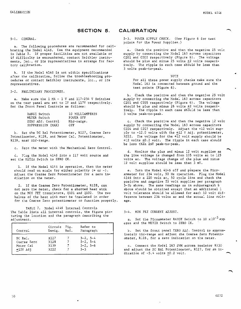
5-1. GENERAL.
a. The f o l l o w i n g p r o c e d u r e s a r e recommended f o r c a l i - b r a t i n g t h e Model 414s. Use t h e equipment recommended i n Tab le 5 . I f p r o p e r f a c i l i t i e s a r e n o t a v a i l a b l e o r i f d i f f i c u l t y i s e n c o u n t e r e d , c o n t a c t K e i t h l e y I n s t r u - ments , I n c . , o r i t s r e p r e s e n t a t i v e s t o a r r a n g e f o r f a c - t o r y c a l i b r a t i o n .
b . I f t h e Model 414s i s n o t w i t h i n s p e c i f i c a t i o n s a f t e r t h e c a l i b r a t i o n , f o l l o w t h e t r o u b l e s h o o t i n g pro- cedures o r c o n t a c t K e i t h l e y I n s t r u m e n t s , I n c . , o r i t s r e p r e s e n t a t i v e s .
5-2. PRELIMINARY PROCEDURES.
a . Make s u r e t h e 1 MA - 1 V and 117-234 V Swi t ches on t h e rear p a n e l are s e t t o 1 V and 117V r e s p e c t i v e l y . Set t h e F r o n t P a n e l C o n t r o l s a s f o l l o w s :
RANGE Switch 10 MILLIAMPERES METER Switch POWER OFF ZERO A D J . C o n t r o l Mid-range. SUPPRESSION (MAX) OFF
b . S e t t h e DC B a l P o t e n t i o m e t e r , R127, Coarse Zero P o t e n t i o m e t e r , R128, and Meter Cal. P o t e n t i o m e t e r , R139, n e a r mid-range.
c . Zero t h e meter w i t h t h e Mechan ica l Zero C o n t r o l .
d . P lug t h e Model 414s i n t o a 117 v o l t s o u r c e and s e t t h e METER Switch t o ZERO C K .
1. I f t h e Model 4145 is o p e r a t i v e , t h e n t h e meter shou ld r e a d on s c a l e f o r e i t h e r p o l a r i t y (+ o r - ) . Adjus t t h e Coarse Zero P o t e n t i o m e t e r f o r a z e r o in - d i c a t i o n on t h e meter.
2. I f t h e Coarse Zero P o t e n t i o m e t e r , R128, c a n n o t z e r o t h e meter, check f o r a s h o r t e d h e a t s i n k on t h e MOS FET t r a n s i s t o r s , Q l O l and Q102. The two h a l v e s of t h e h e a t s i n k must b e i n s u l a t e d i n o r d e r f o r t h e Coarse Zero p o t e n t i o m e t e r t o f u n c t i o n p r o p e r l y .
TABLE 7. Model 414s I n t e r n a l C o n t r o l s The Tab le l i s t s a l l i n t e r n a l c o n t r o l s , t h e f i g u r e p i c - t u r i n g t h e l o c a t i o n and t h e pa rag raph d e s c r i b i n g t h e ad jus tmen t .
C i r c u i t F i g . R e f e r t o C o n t r o l Des ig . Ref . P a r a g r a p h
DC Ba l . 5-2, 5-4 Coarse Zero 5-2, 5-4 Meter Ca l 5-2, 5-6 +12V Adj R222 7 5- 3 -
5-3. POWER SUPPLY CHECK. (See F i g u r e 6 f o r t e s t p o i n t s f o r t h e Power S u p p l i e s . )
a . Check t h e p o s i t i v e and t h e n t h e n e g a t i v e 25 v o l t s u p p l y by c o n n e c t i n g t h e Model 163 a c r o s s c a p a c i t o r s C201 and C202 r e s p e c t i v e l y ( F i g u r e 6 ) . The v o l t a g e s h o u l d b e p l u s and minus 25 v o l t s 2 2 v o l t s r e s p e c t - i v e l y . The r i p p l e i n e a c h c a s e shou ld b e l e s s t h a n 3 v o l t s peak-to-peak.
NOTE For a l l t h e s e power s u p p l y checks make s u r e t h e Model 163 i s connec ted between ground and t h e t es t p o i n t s ( F i g u r e 6 ) .
b . Check t h e p o s i t i v e and t h e n t h e n e g a t i v e 25 v o l t s u p p l y by c o n n e c t i n g t h e Model 163 a c r o s s c a p a c i t o r s C201 and C205 r e s p e c t i v e l y ( F i g u r e 6 ) . The v o l t a g e shou ld b e p l u s and minus 26 v o l t s 2 2 v o l t s r e s p e c t - i v e l y . The r i p p l e i n each c a s e s h o u l d b e l e s s t h a n 3 v o l t s peak-to-peak.
c . Check t h e p o s i t i v e and t h e n t h e n e g a t i v e 1 2 v o l t s u p p l y by c o n n e c t i n g t h e Model 163 a c r o s s c a p a c i t o r s C204 and C207 r e s p e c t i v e l y . A d j u s t t h e - 1 2 v o l t sup- p l y t o -12.0 v o l t s w i t h t h e 2 1 2 V Adj . p o t e n t i o m e t e r , R222. The v o l t a g e f o r t h e +12 v o l t supp ly shou ld be +12 v o l t s 2 0 . 2 v o l t . The r i p p l e i n each c a s e shou ld b e l e s s t h a n 2mV peak-to-peak.
? d. Moni to r t h e p l u s and minus 1 2 v o l t s u p p l i e s a s t h e l i n e v o l t a g e i s changed from 105 v o l t s a c t o 125 v o l t s a c . The v o l t a g e change of t h e p l u s and minus 12 v o l t s u p p l i e s shou ld b e less t h a n 3 m V .
e . Turn t h e Model 414s o f f and p i e p a r e t h e Pico- ammeter f o r 234 v o l t , 50 Hz o p e r a t i o n . P lug t h e Model 414s i n t o a 220 v o l t a c , 50 c y c l e l i n e and check t h e p o s i t i v e and n e g a t i v e 25 v o l t s u p p l i e s p e r pa rag raph 5-3b above. The same r e a d i n g s a s i n subpa rag raph b above s h o u l d b e o b t a i n e d e x c e p t t h a t a n a d d i t i o n a l 1 v o l t t o l e r a n c e s h o u l d b e al lowed f o r each 10 v o l t d i f - f e r e n c e between 234 v o l t s a c and t h e a c t u a l l i n e v o l t - age .
5-4. MOS FET CURRENT ADJUST.
a. S e t t h e Picoammeter RANGE Switch t o 10 x10m3 amp e r e s and t h e METER Switch t o ZERO C K .
b . S e t t h e f r o n t p a n e l ZERO A D J . C o n t r o l t o approx- i m a t e l y mid-range and a d j u s t t h e Coar se Zero P o t e n t i - ome te r , R128, f o r a z e r o i n d i c a t i o n on t h e me te r .
c . Connect t h e Model 163 DVM a c r o s s r e s i s t o r R130 and a d j u s t t h e DC BAL P o t e n t i o m e t e r , R127, f o r an in - d i c a t i o n of -5.4 v o l t s 2 0 . 2 v o l t .
4
,
10 02 7 2

MODEL 414s CALIBRATION
5-5. OFFSET AND NOISE CHECKS.
a. To check t h e o f f s e t :
1. S e t t h e Picoammeter RANGE Swi tch t o 10 x -. AMPERES and t h e METER Swi tch t o ZERO CK. INPUT R e c e p t a c l e and connec t t h e Model 414s t o t h e Model 163 DVM.
Cap t h e
NOTE
When check ing t h e o f f s e t n o i s e , make s u r e t h e Model 414s c o v e r i s on.
2. I f n e c e s s a r y , a d j u s t t h e ZERO ADJ. C o n t r o l f o r z e r o v o l t s a t t h e o u t p u t .
3. S e t t h e RANGE Switch t o .1 x lO-'A. ,Make s u r e t h a t t h e o u t p u t remains a t z e r o v o l t s , a d j u s t i n g t h e f r o n t p a n e l ZERO ADJ. C o n t r o l i f n e c e s s a r y .
4 . S e t t h e METER Switch t o t. The o u t p u t s h o u l d r e m a i n . w i t h i n 210 m i l l i v o l t s .
b . To check t h e n o i s e :
1. Connect t h e Model 414s OUTPUT R e c e p t a c l e t o t h e Model 561A O s c i l l o s c o p e . r
2. S e t t h e METER Swi t ch t o t and v a r y t h e l i n e v o l t a g e from 105 v o l t s ac t o 125 v o l t s a c . The ou t - p u t n o i s e shou ld b e less t h a n 10 m i l l i v o l t s peak-to- peak on a l l r a n g e s .
5-6. METER AND lMA OUTPUT CALIBRATION.
a. S e t t h e RANGE Switch t o 1 MICROAMPERE. Connect t h e Model 261 Picoampere Source t o t h e Model 414s IN- PUT R e c e p t a c l e and connec t t h e Model 163 DVM t o t h e OUTPUT R e c e p t a c l e .
b . 6 S e t t h e Model 414s METER Switch t o + and app ly 10- ampere w i t h t h e Model 261. I f n e c e s s a r y , a d j u s t t h e ZERO ADJ. C o n t r o l f o r e x a c t l y 1 ,000 v o l t a t t h e o u t p u t .
c . A d j u s t t h e Meter Cal P o t e n t i o m e t e r , R139, f o r f u l l scale meter d e f l e c t i o n .
d . Load t h e Model 414s o u t p u t w i t h a 1 . 5 ki lohm re- s i s t o r and se t t h e 1 V - 1 MA Switch t o 1 MA.
e . A d j u s t t h e rear p a n e l 1 MA CAL C o n t r o l and n o t e t h a t t h e o u t p u t v o l t a g e can b e a d j u s t e d a t least 0 . 1 v o l t e i t h e r s i d e of 1 . 5 v o l t s .
f . Remove t h e 1 . 5 k i lohm l o a d and se t t h e 1 V - 1 MA Switch t o 1 V .
g . S e t t h e METER Switch t o ZERO CK and r e -ze ro t h e o u t p u t i f n e c e s s a r y .
5-7. RANGE ACCURACY CHECK.
a . Connect t h e Model 4145 INPUT ReceF tac l e t o t h e Model 261. Connect t h e OUTPUT R e c e p t a c l e t o t h e Model 163 DVM.
b . Check t h e f u l l - s c a l e accu racy of a l l p o s i t i o n s on Check b o t h p o s i t i v e and n e g a t i v e in- t h e RANGE Swi t ch .
p u t s t o e n s u r e p r o p e r o p e r a t i o n of b o t h p o l a r i t i e s a t v a r i o u s c u r r n t i n p u t l e v e l s . Chec t h e accu racy of t h e 10 x 1 0 o f f u l l s c a l e a t t h e o u t p u t (1.O-golt 220 m i l l i v o l t s ) . Ch_e§k t h e a c c u r a c y of t h e 3 x 10 1 0 v o l t 240 m i l l i v o l t s ) .
-9 -b A th rough t h e 10 x 1 0 A r a n g e s t o 2 2 %
A th rough t h e .1 x A r a n g e s t o 2 4 % of f u l l s c a l e a t t h e o u t p u t (1 .0
- -1
UHF I
I" - - - - - - - - I series
b14A
r 1 iK r e s i s t o r s U
s h u n t I c a p a c i t o r 2 '--,,--,,,, - -
a 561,\
FIGURE 5. t o r s o r c a p a c i t o r , UHF-Tee and t h e Shunt C a p a c i t o r .
Test Set-up f o r Model 414s Rise T i m e Check on a l l r a n g e s . B e s u r e t o p r o p e r l y s h i e l d t h e s e r i e s r e s i s -
0272 11

CALIB.WTION MODEL 414s
5-8. RISE TIME CHECK. To check t h e r ise t i m e of t h e Model 4145 r e q u i r e s two d i f f e r e n t t es t s e t - u p s . The f i r s t s t up is f o r checkQg t h e r i se times on t h e 1 x 10 A th rough 10 x 10 A r a n g e s . The second set- u p - 4 ~ f o r check ing t h e r ise times on t h e r a n g e s 1 x 10 A and below.
-5 -
a. 1 x 10⁻³A th rough 10 x lO-’A r a n g e s . S e t t h e tes t f i x t u r e as i l l u s t r a t e d i n F i g u r e 5 .
1. Equipment used (Refe r t o Tab le 5 ) : The Model 202A F u n c t i o n G e n e r a t o r , s i x s h i e l d e d r e s i s t o r s rang- i n g i n v a l u e from 3 k i lohms t o 300 megohms (See T a b l e 8 ) , a UHF Tee c o n n e c t o r , a 500 pF p o l y s t y r e n e s h u n t c a p a c i t o r , t h e Model 414s and t h e Model 561A O s c i l l o - s cope . The o s c i l l o s c o p e used must b e d c coup led .
TABLE 8. Model-614S R i s e T i m e Check f o r 1 x 10⁻³A th rough 10 x 10 A Ranges. The Tab le g i v e s t h e Model 414s RANGE Swi t ch s e t t i n g s , t h e F u n c t i o n G e n e r a t o r f r equency s e t t i n g s , t h e series r e s i s t o r u sed f o r e a c h RANGE Switch s e t t i n g , and t h e maximum a l l o w a b l e r ise time .
I
F u n c t i o n Model 414s Genera t o r Maximum
RANGE Switch S e r i e s Frequency Rise. T i m e S e t t i n g R e s i s t o r s (Hz) ( m i l l i s e c o n d s
1 ~ o - ~ A 3 k Q 250 less t h a n 1 .1 1 0 - 3 ~ 30 k Q 250 less t h a n 1 10 x 10-6A 300 k Q 250 less t h a n 1 1 x 10⁻⁶A 3 MQ 2 .5 50
10 1 0 - 9 ~ 300 Ma 2.5 130 . i x 1 0 - 6 ~ 30 MQ 2.5 90
2. P rocedures :
a ) Apply a s q u a r e wave from t h e Model 202A F u n c t i o n G e n e r a t o r a c r o s s t h e s e l e c t e d series re- s i s t o r , t h rough t h e UHF Tee t o t h e Model 414s I N - PUT R e c e p t a c l e . Observe t h e o u t p u t of t h e Model 414s w i t h t h e Model 561A.
b ) For e a c h Model 414s r a n g e , u s e t h e Model 202A f r equency s e t t i n g and t h e s e r i e s r e s i s t o r i n d i - c a t e d i n T a b l e 8.
c ) A d j u s t t h e Model 202A a m p l i t u d e c o n t r o l as needed t o o b t a i n 2 v o l t s peak-to-peak a t t h e Model 414s o u t p u t . Check t h e 10 - 90% rise t i m e t o t h e f i g u r e s shown i n T a b l e 8 .
b . 1 x lO-’A and .1 x lO-’A r a n g e s . S e t t h i s t es t f i x t u r e up as i l l u s t r a t e d i n F i g u r e 5 , e x c e p t t h a t a s h i e l d e d 50 pF p o l y s t y r e n e c a p a c i t o r shou ld b e sub- q t i t u t e d f o r t h e s e r i e s r e s i s t o r s between t h e F u n c t i o n . - - ? r a t o r and t h e UHF ‘ ~ C P - .
1. Equipment Used: T h i s tes t se t -up u s e s t h e same equipment of t h e p r e v i o u s se t -up w i t h t h e e x c e p t i o n of t h e 50 pF p o l y s t y r e n e c a p a c i t o r . The c a p a c i t o r i n t h i s s e t -up s e r v e s a similar f u n c t i o n as t h e series r e s i s t o r s i n t h e p r e v i o u s t es t s e t - u p .
2. P r o c e d u r e s :
a ) Apply a t r i a n g u l a r wave from t h e Model 202A a c r o s s t h e c a p a c i t o r , t h rough t h e UHF Tee t o t h e Model 414s INPUT R e c e p t a c l e . Monitor t h e Model 414s o u t p u t w i t h t h e Model 561A. Use t h e p rope r Model 202A f r equency s e t t i n g as i n d i c a t e d i n T a b l e 9 . 1
b ) A d j u s t t h e Model 202A ampl i tude c o n t r o l as needed t o o b t a i n 2 v o l t s peak-to-peak a t t h e Model 414s o u t p u t . Check t h e 1 0 - 90% r i se t ime t o t h e * f i g u r e s shown i n Tab le 9 .
TABLE 9 . Model 414A R i s e Time Check f o r 1 x lO-’A and .1 x lO-9A Ranges. 414s RANGE Switch s e t t i n g s , t h e F u n c t i o n Genera to r f r equency s e t t i n g s , and t h e maximum a l l o w a b l e rise t i m e .
The Tab le g i v e s t h e Model
Model 414s F u n c t i o n Genera to r Maximum RANGE Swi tch Frequency Rise Time
S e t t i n g (Hz) (mi lli seconds )
1 1.0 150 .I 10-9 0.25 750
5-9. DRIFT VERIFICATION. - a . Shunt t h e I n p u t of t h e Model 414s w i t h a 10-ki l -
ohm r e s i s t o r w i t h t h e RANGE Switch se t t o 1 x 10’6A and t h e METER Switch se t t o + o r -, a s n e c e s s a r y , Using t h e s h u n t i n c r e a s e s t h e s e n s i t i v i t y 100 t imes .
NOTE
While d o i n g t h e d r i f t r u n make s u r e t h e Model 414s cove r i s on.
b . Connect t h e Model 370 Recorder t o t h e Model 414s. S e t t h e Recorde r a t t e n u a t o r t o 1 v o l t (10 m i l l i v o l t s d r i f t f u l l s c a l e ) o r 0 . 3 v o l t s ( 3 mV f u l l s c a l e ) .
c . S e t t h e METER Switch t o + and a d j u s t t h e ZERO ADJ C o n t r o l f o r n e a r z e r o v o l t s o u t p u t . The ZERO ADJ Con- t r o l i s v e r y s e n s i t i v e w i t h t h e s e n s i t i v i t y i n c r e a s e d 100 times. S e t t h e METER Switch t o - i f t h e d r i f t is n e g a t i v e ,
d . A f t e r a 10-minute warm-up, t h e Model 414s may d r i f t 700 m i c r o v o l t s p e r 24 h o u r s p l u s o r minus 500 m i c r o v o l t s p e r ‘C change i n t e m p e r a t u r e .
e . I n some c a s e s , t h e 24-hour d r i f t may appear mar- g i n a l o r i t may b e s l i g h t l y o u t of s p e c i f i c a t i o n due t o a s t e e p d r i f t s l o p e d u r i n g t h e e a r l y p a r t of t h e d r i f t . I f t h i s i s s o , i t may b e d e s i r e d t o c o n t i n u e t h e d r i f t f o r a n a d d i t i o n a l 24 h o u r s and c a l c u l a t e a weeks d r i f t as f o l l o w s :
-,
1. M u l t i p l y t h e d r i f t d u r i n g second 24-hour p e r i o t ? times 6 and add t h e d r i f t no ted d u r i n g t h e f i r s t 24- hour p e r i o d .
2 . T o t a l d r i f t shou ld n o t exceed 5 mV.
1 “ IL 0272

MODEL 414s CALIBRATION
r 5-10. SUPPRESSION CHECK.
a. Cap t h e i n p u t of t h e Model 414s and connec t t h e o u t p u t t o t h e Model 163.
b . S e t t h e f r o n t p a n e l c o n t r o l s as follows:
RANGE Switch 1 10-3 METER Switch (+)
SUPPRESSION, MAX AMPERES Switch 10-3 SUPPRESSION, P o l a r i t y C o n t r o l (-)
ZERO ADJ. C o n t r o l Mid-range
c . Ad jus t t h e SUPPRESSION, FINE C o n t r o l f o r a f u l l scale meter d e f l e c t i o n . Monitor t h e o u t p u t v o l t a g e on t h e 163 and a d j u s t t h e SUPPRESSION, FINE C o n t r o l f o r maximum s u p p r e s s i o n . A t maximum s u p p r e s s i o n , t h e o u t p u t v o l t a g e observed on t h e Model 163 shou ld b e g r e a t e r t h a n 1.1 v o l t s (10% over - r ange ) .
d . S e t t h e f r o n t p a n e l c o n t r o l s as follows:
RANGE Switch .I 10-3 METER Switch (+)
SUPPRESSION, P o l a r i t y C o n t r o l (-1
ZERO ADJ. C o n t r o l Mid-range SUPPRESSION, I4AX AMPERES Switch 10-4
g. Then, set t h e f r o n t p a n e l c o n t r o l s as f o l l o w s :
1 10-3 RANGE Switch
ZERO ADJ. C o n t r o l Mid-range METER Switch (-)
SUPPRESSION, MAX AMPERES Switch 10-3 SUPPRESSION, P o l a r i t y C o n t r o l (+I
Repeat t h e p rocedures o u t l i n e d i n sub-paragraph c , d and e above.
h . S e t t h e f r o n t p a n e l c o n t r o l s a s f o l l o w s :
RANGE Switch 10 10-9 METER Switch (+I ZERO ADJ. C o n t r o l Mid-r ange SUPPRESSION, MAX AMPERES Switch OFF SUPPRESSION, P o l a r i t y C o n t r o l (+I
With t h e Model 261 a p p l y 10-8 ampere t o t h e Model 414s i n p u t . Model 561A o s c i l l o s c o p e .
Monitor t h e o u t p u t w i t h a 5 mV/div a c coupled
i. S e t t h e SUPPRESSION, MAX AMPERES Switch t o 10-8 and a d j u s t t h e SUPPRESSION, FINE C o n t r o l to buck o u t t h e i n p u t s i g n a l as t h e RANGE Switch i s changed t o .I 10-9,
e. Ad jus t t h e SUPPRESSION, FINE C o n t r o l f o r a f u l l j . Meter n o i s e shou ld b e less t h a n 2% (one minor s c a l e meter d e f l e c t i o n . d i v i s i o n ) . Output n o i s e observed on t h e o s c i l l o s c o p e
s h o u l d b e less t h a n 10 mV peak-to-peak, e x c l u d i n g any low f r equency component. f . Using t h e method d e s c r i b e d i n pa rag raph b above,
tes t t h e s u p p r e s s i o n f o r each s e t t i n g of t h e RANGE Switch, u s i n g c o r r e s p o n d i n g s e t t i n g s of t h e SUPPRESSION, MAX AMPERES Switch. The o u t p u t v o l t a g e n o t e d on t h e Model 163 s h o u l d n o t v a r y more t h a n 5 4 % .
0272 13

CALIBRATION !IODEL 4 1 4 5
FIGURE 6. Chassis, Top V i e w .
14 0 2 7 2

PIC2EL 4 1 4 s CALIBRATION
F I G U R E 7 . Component Layou t , PC180.
a 2 7 2 15

ACCESSORIES
SECTION 6 . ACCESSORIES
MODEL 414s
6-1. GENERAL. The fo l lowing K e i t h l e y a c c e s s o r i e s 6-2. OPERATING INSTRUCTIONS. A s e p a r a t e I n s t r u c t i o n can be used wi th t h e Model 414s t o provide a d d i t i o n a l convenience and v e r s a t i l i t y . o p e r a t i n g informat ion .
Manual i s suppl ied w i t h each accessory g i v i n g complete
Model 6106 Elec t rometer Connection K i t
De sc r i p t ion : P a r t s L i s t : I tem Kei th ley
The Model 6106 c o n t a i n s a group of t h e most u s e f u l D e s c r i p t i o n No. P a r t No. leads and a d p a t e r s f o r low c u r r e n t measurements. A l l components a r e housed i n a rugged c a r r y i n g c a s e w i t h Cable , 30", UHF t o c l i p s 1 19072C i n d i v i d u a l compartments. Cable , 24", UHF t o UHF 2 18265C
Connector , UHF t o UHF 3 c s - 5 Adaptor , UHF t o BNC 4 CS-115 Adaptor , UHF t o BNC 5 CS-172 Adaptor Tee, UHF t o UHF 6 CS-171 Adaptor , Binding Post 7 19071B
The two c a b l e s ( I tems 1 and 2) a r e c o a x i a l sh ie lded l e a d s u s e f u l f o r connec t ions where low n o i s e i s essen- t i a l . The 24" c a b l e ( I tem 2) can be used t o in te rcon- n e c t two ins t ruments having UHF r e c e p t a c l e s . The 30" c a b l e ( I tem 1) can be used t o connect t o t h e c i r c u i t under t e s t through t h e use of c l i p l e a d s . A b inding pos t a d a p t e r g i v e s easy a c c e s s t o t h e e l e c t r o m e t e r "high" t e r m i n a l . Two UHF female couplers ( I tem 3 ) permit c a b l e s t o be connected t o g e t h e r . connec tor s i m p l i f i e s galvanometr ic c u r r e n t measurements when us ing a c u r r e n t source and e l e c t r o m e t e r o r pico- ammeter. Adapters ( I tems 4 and 5) a r e u s e f u l f o r con- v e r s i o n from UHF t o BNC te rmina t ions .
The UHF "tee"
Model 261 Picoampere Source
Descr ip t ion :
The Model 261 i s an a c c u r a t e picoampere c u r r e n t source w i t h 3 d i g i t r e s o l u t i o n . The output ranges a r e ampere t o 1.1 x 10⁻⁴ ampere, p o s i t i v e o r n e g a t i v e , i n e i g h t decade ranges. Accuracy is r a t e d from 2.25% t o - +1.6% e x c l u s i v e of input drop c o n s i d e r a t i o n s .
Appl ica t ion :
The Model 261 i s a secondary s tandard f o r use i n ca l i - b r a t i n g picoammeters and e l e c t r o m e t e r s . It can a l s o be used a s an a c c u r a t e c u r r e n t source f o r zero suppress ion and f o r galvanometr ic measurements.
3
16 0272

MODEL 414s ACCESSORIES
r Model 4003A Rack Mounting Kit
Description:
The Model 4003A.i~ a rack mounting kit with overall dimensions, 5-1/4 inches high x 19 inches wide. Two top covers are provided for use with either 10 inch or 13 inch deep instruments.
Application :
The Model 4003A converts the instrument from bench mounting to rack mounting. It is suitable for mount- ing one instrument in one-half of a standard 19-inch rack.
Parts List:
Item No. 1 2 3 4 5 6 7 8
Description Top Cover, 10" Panel Adapter Plate Angle Support Screw,#lO x 318" Connecting Plate Screw, 1/10 x 1 /2 " Angle Top Cover, 13"
Qty. Per Keithlev Part No. Assembly
1 18554B 1 17452B 1 17476A 4 1 19126A 4 1 14624B 1 20015B
--- ---
Model 4004A Dual Rack Mounting Kit
Description : Parts List:
The Model 4004A is a rack mounting kit with overall Item Qty. Per Ke it h ley Part No. dimensions, 5-114 inches high x 19 inches wide. Two No. Description As semb 1 y
p top covers are provided for use with either 10 inch 1 Top Cover, 10" 2 18554B
r
or 13 inch deep instruments. 4 Screw, 110 x 1/2 8 5 Connecting Plate 1
Application : 6 Screw, 1/10 x 1/2 4 7 Angle 2
The Model 4004A converts the instrument from bench 8 Top Cover, 13" 2 mounting to rack mounting. It is suitable for mount- 9 Zee Bracket 1 ing two instruments in a standard 19-inch rack. 10 Plate (not shown) 1
--- 191268
14624B 20015B 19144A 17454A
---
02 72 17

ACCESSORIES
Model 4104 Electronic Trip
The Model 4104 is an electronic trip installed in the picoameter to provide automatic current control. Combinations of high, low, 2 polarity, and latching is available.
MODEL' 4145
Model 4109 Polarizing Supply
The Model 4109 provides +300 volts at 1 mA for appli- cations requiring a stable voltage source. The Model 4109 can be ordered installed in the picoameter if desired.
? Models 240A, 244, 245, 246 Voltage Supplies
De s c r i pt ion :
Keithley voltage supplies are highly-stable, low-noise power supplies for voltages up to 23100 volts dc.
Application :
Keithley voltage supplies are commonly used with pico- ammeters in the measurement of resistance, light levels (photomultipliers), and radiation intensity (ion chambers). These high voltage supplies have been designed to operate with the Keithley line of electrometers, picoameters and resistivity accessories. A typical application is shown using the Model 414s (or 414A) and the Model 240A in a photomultiplier experiment.
Output Ranges :
Model No. 2 40A
Voltage 0 to +12oov
2 44 -200 to -2200v 2 45 0 to +21oov 2 46 0 to ~3100V
18 0172

E A 1
F
E l e c t r o l y t i c , Aluminum
Farad
MODEL 414s
P
REPLACEABLE PARTS
SECTION 7 . REPLACEABLE PARTS
7-1 . REPLACEABLE PARTS L I S T . The R e p l a c e a b l e P a r t s L i s t d e s c r i b e s t h e components of t h e Model 414s . The L i s t g i v e s t h e c i r c u i t d e s i g n a t i o n , t h e p a r t d e s c r i p - t i o n , a s u g g e s t e d m a n u f a c t u r e r , t h e m a n u f a c t u r e r ' s p a r t number and t h e K e i t h l e y P a r t Number. The l a s t column i n d i c a t e s t h e f i g u r e p i c t u r i n g t h e p a r t . The name and a d d r e s s o f t h e m a n u f a c t u r e r s l i s t e d i n t h e "Mfg. Code" column are i n T a b l e 1 4 .
and s e r i a l number, t h e K e i t h l e y Part Number, t h e c i r - c u i t d e s i g n a t i o n and a d e s c r i p t i o n of t h e p a r t . A l l s t r u c t u r a l p a r t s and t h o s e p a r t s coded f o r K e i t h l e y m a n u f a c t u r e (80164) must b e o r d e r e d th rough K e i t h l e y I n s t r u m e n t s , I n c . , o r i t s r e p r e s e n t a t i v e s . I n o rde r - i n g a p a r t n o t l i s t e d i n t h e R e p l a c e a b l e P a r t s L i s t , c o m p l e t e l y d e s c r i b e t h e p a r t , i t s f u n c t i o n and i t s l o c a t i o n .
7-2. HOW TO ORDER PARTS. b . Order p a r t s t h rough your n e a r e s t K e i t h l e y rep- r e s e n t a t i v e o r t h e Sales S e r v i c e Depar tmen t , K e i t h l e y
a . For p a r t s o r d e r s , i n c l u d e t h e i n s t r u m e n t ' s model I n s t r u m e n t s , I n c .
TABLE 1 2 . A b b r e v i a t i o n s and Symbols.
F i g .
GCb
k
P M Mfr . Mtf MY
F i g u r e
Glass Enc losed c a r b o n
k i l o ( l o 3 )
m i c r o (10-6) Mega ( l o 6 ) Manufac tu re r Xeta l F i l m Mylar
n
P Po ly
R e f .
V
W W a r
ohm
p i c 0 (10-12) P o l y s t y r e n e
Refe rence
V o l t
Watt Wirewound V a r i a b l e
MODEL 414s REPLACEABLE PARTS L I S T ( R e f e r t o Schemat i c Diagram 22394E f o r c i r c u i t d e s i g n a t i o n s . )
CAPACITORS
C i r c u i t Mfr. Mfr. K e i t h l e y F i g . Des ig . Value R a t i n g Type Code Des ig . P a r t No. Ref .
C l O l c102 C103 C104 C105
.25 PF
.1 PF - 0 2 PF .0.2 pF .0047 PF
400 V 400 V
1000 v 1000 v 1000 v
MY MY CerD CerD CerD
13050 13050 56289 56289 56289
SMlA C73-. 25M S M l A C73-. 1X 10ss - s20 C22-. 02M 10ss - s20 C 2 2 - .02M 10SS-D47 C22-.0047M
C106 C107 C108 c109 C l l O
-0022 PF 680 pF .01 PF .0033 pF .0022 PF
1000 v 1000 v to00 'V 1000 v 1000 v
CerD CerD C e r D C e r D CerD
72982 71590 56289 56289 72982
811000X5F0222K C22-.0022M DD-681 C22-680P loss- s10 C 2 2- . 0 1 M 10SS-D33 V33-.0033M 811000X5F0222K C22-.0022M
C l l l c112
680 pF 220 pF
1000 v 500 V 500 V 500 V 500 V
CerD P o l y P o l y P o l y C e r D
71590 71590 71590 71590 72982
DD-681 C 2 2-6801) CPR- 220 J C138-220P CPR-47J C138-47P CP R- 2 2 J C138-22P 851-25U0-682M C22-.0068M
C113 47 pF r C114 22 pF
C115 .0068 uF*
*Nominal v a l u e . r
0675 19

REPLACEABLE PARTS MODEL 414s
T CAPACITORS ( c o n t ' d )
C i r c u i t Mfr . Mfr . Kei t h l e y F i g . Des i g . Value R a t i n g Type Code D e s i g , P a r t No. R e f .
c 2 0 1 100 IJF 40 V E A 1 73445 C437AR/G100 C150-100M 7 c202 .02 lJF 1000 v CerD 56289 loss- s 20 C22-. 02M 7 C203 .02 iJF 1000 v CerD 56289 10s s-s20 C22- .02M 7 C204 100 iJF 40 V EA1 73445 C437AR/G100 C150-100M 7 C205 100 lJF 40 V E A 1 73445 C437AR/G100 C150-100M 7
C206 .01 ~ J F 1000 v CerD 56289 10 s s-s20 C22- .01M 7 C207 100 pF 40 V E A 1 73445 C437AR/G100 C150-100M 7
DIODES
C i r c u i t D e s i g . Type
Mfr . Code
Mfr . D e s i g .
Kei t h l e y P a r t No.
F i g . Ref .
D l O l D102 D103 D104 D105
S i l i c o n S i l i c o n S i l i c o n Zene r S i l i c o n
01295 02735 02735 84970 02735
1N645 1N3255 1N3255 VR47 1N3255
RF- 1 4 RF- 1 7 RF-17 DZ-30 RF-17
D106 D107
S i l i c o n S i l i c o n
01295 01295
1N645 1N645
RF-14 RF-14
7 7
D201 D202 D203 D204 D205
S i l i c o n S i l i c o n S i l i c o n S i l i c o n Zene r
01295 01295 01295 01295 12954
1N645 18645 1N645 1N645 1N706
RF-14 RF-14 RF- 1 4 RF- 1 4 D Z - 1
7
; - 7 7
D206 D207 D208
Zene r S i l i c o n Zene r
12954 01295 04713
1N706 1N645 1N936
D Z - 1 RF-14 DZ-5
7 7 7
MISCELLANEOUS PARTS
C i r c u i t Mf r . M f r , K e i t h l e y F i g . D e s i g . D e s c r i p t i o n Code D e s i g . P a r t No. R e f .
21850B
DS201
F201 (117V) F201 (234V)
5 1 0 1
P l O l
5102 --- ---
5103 ---
M l O l
P201
MOS FET I n p u t P l u g - i n Card
P i l o t L i g h t , Neon
F u s e , Slow b low, 1 / 8 A F u s e , Slow b low, 1 / 1 6 A
P r i n t e d C i r c u i t C o n t a c t s
P r i n t e d C i r c u i t C o n t a c t s , mate of 5 1 0 1
R e c e p t a c l e , UHF, INPUT P l u g , UHF, mate of 5102 Cap
R e c e p t a c l e , Mic rophone , OUTPUT P l u g , Mic rophone , mate of 5103
Meter
AC Power C a b l e , 6 f e e t
80164
91802
71400 7 1400
91662
91662
91737 02660 91.737
02660 02660
80164
93656
23734A 6
PL-28 2
FU-20 3 FU-21
CS-199
cs -200
CS-64 3 cs -49 CAP-4 1
CS-32 3 c s -33
ME-78 6 7
CO- 5
2190
MDL MD L
02-005-113-6-200
02-005-111-5-200
6804
7901 83-822
80-PC2F 80-MC2M
46 38- 1 3
0272 20

SODEL 414s
P
~~
REPLACEABLE PARTS
MISCELLANEOUS PARTS
C i r c u i t Des ig . D e s c r i p t i o n
Mfr. Mfr . Code Des ig .
K e i t h l e y F i g . P a r t No. Ref.
C i r c u i t
Ro ta ry Swi t ch , METER Knob Assembly, Meter Switch
80164 80164
Ro ta ry Switch less components, 80164 SUPPRESS I ON Ro ta ry Switch w i t h components, 80164 S u p p r e s s i o n Knob Assembly, S u p p r e s s i o n Switch 80164
Rotary Switch less components, RANGE 80164 Ro ta ry Switch w i t h components, Range 80164 Knob Assembly, Range Switch 80164
Ro ta ry Swi t ch , S u p p r e s s i o n P o l a r i t y 80164 Ro ta ry Switch w i t h components, P o l a r i t y 80164 Knob Assembly, P o l a r i t y Switch 80164 S l i d e S w i t c h , 1 MA - 1 V 79727
S l i d e Swi t ch , 1 1 7 V - 234 V 80164
Knob Assembly, 1 MA CAL C o n t r o l 80164 Knob Assembly, S u p p r e s s i o n FINE C o n t r o l 80164 Transformer 80164
RESISTORS
Mfr. Des ig . Value R a t i n g Type Code
G326
SW-244 216608
SW-262
22135B
21660A
SW-243 21848B 21651A
SW-261 22136B 20382A sw-45
SW-151
16373A 16995A TR-112
Mfr. K e i t h l e y Desig . P a r t No.
2
2
2
2
3
3
7
F i g . Ref.
R l O l R102 R10 3 R104 R105
R106 R10 7 R10 8 R109 R l l O
R l l l R112 R113 R114 R115
R116 R117 R118 R119 R120
R 1 2 1 R122 R123 R124 R125
P
-
1010 R 109 R 108 R 107 R 106 n
105 R 104 R 10 kR 300 R 1 kQ
3 kR 10 kR 30 kR 100 kQ 300 kR
1 MQ 3MG 10 MR 30 MR 100 m 109 R 1010 R 2 kR 1 kR 1m
3% 3% 1%, 2 w 1%, 112 w 1%, 1 1 2 w
1%, 112 w 1%, 112 w 5 % , 2 w 1%, 112 w 1%, 1 1 2 w
1%, 1 1 2 w 1%, 1 1 2 w 1%, 1 1 2 w 1%, 1 w 1%, 112 w
1%, 1 1 2 w 1%, 1 1 2 w 1%, 112 w 1%, 1 w 1%, 2 w
3% 3% 1%, 112 w 1 / 2 % , 1/2w 1%, 112 w
GCb GCb DCb DCb DCb
DCb DCb W a r DCb DCb
DCb DCb DCb
DCb
DCb DCb DCb DCb DCb
GCb GCb MtF MtF DCb
EPOXY
63060 63060 91637 07716 91637
07716 07716 12697 91637 91637
07716 07716 91637 9 16 37 07716
91637 91637 07716 91637 91637
63060 63060 07716 07716 91637
Rx- 1 Rx- 1 D C - 2 D C C DCF- 1 / 2
D C C D C C 62JA DCF-112 DCF-112
DC C D C C DCF-112 MMF- 1 D C C
DCF-112 DCF- 1 12 D C C D C - 1 DC-2
Rx- 1 Rx- 1 C E C CEC DCF-112
R20- lolo
R14- l O O M R12-10M R12-1M
~ 2 0 - 1 0 9
R12-100K R12-10K RP 4 2- 10K R12-300 R12-1K
R12-3K R12-10K R12-30K R150-100K R12-300K
R12-1M R12-3M R12-10M R13-30M R 1 4 - 10 ON
R20- 109 R20-1010 R61-2K R6 1- 1K R 1 2 - 1 M
- - - - - - - - 6 6
6 6 6 6 6
6 6 6 6 6
6 6 6 6 7
02 72 21
REPLACEABLE PARTS MODEL 414s
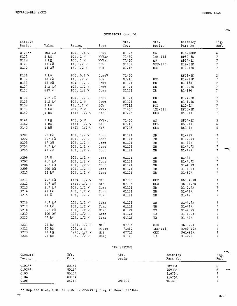
9 RESISTORS (cont'd)
Circuit Mfr. Mfr. Kei thley Fig. Desig. Value Rating Type Code Desig. Part No. Ref.
R126** 100 kn 10%) 114 W Comp 01121 CB R76-100K 6 R127 5 kn 20%) 2 w W a r 71450 1NS-115 RP50- 5K 7 R128 1 kn lo%, 5 w W a r 71450 AW RP34-1K 7 R129 13 kn 1%, 112 w DCb 91637 DCF-112 R12-13K 7 R130 18 kn 1%) 112 w DCb 07716 DCC R12-18K 7
R131 2 kn 20%) 0.2 W CompV 71450 RP3 1- 2K 2 R132 18 kn 1%, 112 w DCb 07716 DC C R12-18K 7
R134 2.2 kn 10%) 112 w Comp 01121 EB R1-2.2K 7 R135 680 lo%, 112 W Comp 01121 EB R1-680 7
R136 4.7 kn lo%, 112 W Comp 01121 EB Rl-4 I 7K 7 R137 1.2 kn lo%, 2 w Comp 01121 HB R3-1.2K 7 R138 2 kn 1%, 112 w DCb 07716 DCC R12-2K 7 R139 2 kn 20%, 2 w W a r 7 1450 1NS-115 RP50- 2K 7 R140 ,1 kQ 1/2%, 112 W MtF 07716 CEC R6 1- 1K 7
7 R1-15K R133 15 kn 10%. 112 w Comp 01121 EB
R141 1 kfl 10%) 5 w W a r 71450 AW RP34-1K 3 R142 1 kn 112%) 112 W MtF 07716 CEC R6 1- 1K 6 R143 1 kn 1/2%, 112 W MtF 07716 CEC R6 1- 1K 6
R201 27 kQ lo%, 112 w Comp 01121 EB R1-27K 7 R202 2.7 kn 10%) 112 W Comp 01121 EB R1-2.7K 7 R203 47 kn lo%, 112 w Comp 01121 EB R1-47K 7 R204 4.7 kn lo%, 112 w Comp 01121 EB Rl-4.7K 7 R205 47 kfl lo%, 112 w Comp 01121 EB R1-47K 7 -
R206 47 n 10%) 1 1 2 w Comp 01121 EB R1-47 7 R207 4.7 ka lo%, 112 w Comp 01121 EB Rl-4.7K 7 R208 4.7 ki-2 lo%, 112 W Comp 01121 EB Rl-4.7K 7 R209 100 kn lo%, 112 W Comp 01121 EB R1-100K 7 R2 10 82 kn lo%, 112 W Comp 01121 EB R1-82K 7
R211 4.7 kn 1/2%, 112 W MtF 07716 CEC R61-4.7K 7 R212 4.7 kn 1/2%, 112 W MtF 07716 CEC R61-4.7K 7 R213 2.7 kn lo%, 112 W Comp 01121 EB R1-2.7K 7 R214 47 ka 10%) 112 W Comp 01121 EB R1-47K 7 R215 47 10%) 112 w Comp 01121 EB R1-47 7
R2 16 4.7 kn lo%, 112 w Comp 01121 EB R1-4.7K 7 R217 47 kn lo%, 112 w Comp 01121 EB R1-47K 7 R218 2.7 kn lo%, 112 w Comp 01121 EB R1-2.7K 7 R2 19 100 kn lo%, 112 w Comp 01121 EB R1-100K 7 R220 47 kn lo%, 112 w Camp 01121 EB R1-47K 7
R221 22 kQ 112%) 112 W MtF 07716 CEC R6 1-22K 7 R222 10 kn 20%, 2 w W a r 71450 1NS-115 RP 5 0- 10 K 7 R223 91 m 1 1 2 % ) 112 W MtF 07716 CEC R61-91K 7 R224 27 w2 lo%, 112 w Comp 01121 EB Rl-27K 7
TRANSISTORS
Circuit Mfr. Mfr. Kei t hley Fig. Desig. Code Desig . Part No. Ref.
?
Q101** Q102** Q103 Q104 Ql05
80164 80164 80164 80164 04713 2N3904
20933A 20933A 21675A 21675A TG-47
6 6 7 7 7 7
** Replace R126, QlOl or Q102 by ordering Plug-in Board 23734A. 22 02 72
MODEL 414s
C i r c u i t D e s i g .
Mfr . Code
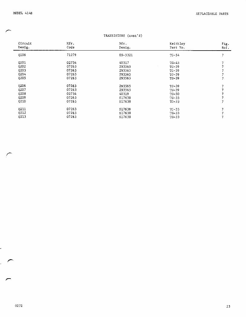
TRANSISTORS ( c o n t ' d )
M f r . D e s i g .
K e i t h l e y P a r t No.
REPLACEABLE PARTS
F i g . R e f .
Q106
4201 Q202 4203 4204 Q205
4206 4207 4208 4209 Q210
4211 Q212 Q213
71279
02734 07263 07263 07263 07263
07263 07263 02734 07263 07263
07263 07263 07263
ES-5 321
40317 2N3565 2N3565 283565 2N3565
2N3565 2N3565 40319 S17638 S17638
S17638 S17638 S17638
TG-54
TG-43 TG-39 TG- 3 9 TG- 3 9 TG-39
TG-39 TG-39 TG-50 TG-33 TG-33
TG-33 TG-33 TG- 3 3
7
7 7
02 72 23

REPLACEABLE PARTS
TABLE 1 3 . Mechan ica l P a r t s L i s t
~ 7
MODEL 414s
D e s c r i p t i o n
1) C h a s s i s
11) F r o n t P a n e l
Top Cover Assembly
1 2 ) Cover , Shee t Me ta l
13 ) Screws
Handle Assembly
14 ) Handle
1 5 ) Screws 1\6-32 x 3/8" R . H . S l o t t e d
Bottom Cover Assembly
2 ) Cover
3) F a s t e n e r
F e e t Assembly
4) Fee t
5 ) B a l l
6 ) Screws 118-32 x 3/8" P h i l l i p s , Pan Head
T i l t B a i l Assembly
7 ) Ba i l
8 ) R igh t Assembly
9 ) L e f t Assembly
10) Screws 86-32 x 1 / 4 " P h i l l i p s , Pan Head
Q u a n t i t y Pe r Assembly
I
" L
Kei t h l e y P a r t No.
24021B
21658C
18553B
17131D
--- ---
HH-18
---
19 29 8 C
19340B
FA-54
---
FE-5
FE-6
--- ---
17147B
19206B
19205B
---
Fig . Ref.
8
8
9
24 0272

MODEL 414s
- ~~
REPLACEABLE PARTS
cp’
FIGURE 8. T o p C o v e r A s s e m b l y .
F IGURE 9. B o t t o m C o v e r A s s e m b l y . 03 72 25

CODE-TO-NAME LIST
_ _ -
MODEL 414s
TABLE 14. T Code List of Suggested Manufacturers. (Based on Federal Supply Code for Manufacturers, Cataloging Handbook H 4 - 1 ) .
01121
01295
02660
02735
04713
07716
12954
13050
63060
71279
71400
Allen-Bradley Corp. 1201 South 2nd Street Milwaukee, Wis. 53204
Texas Instruments, Inc. Semiconductor-Components Division 13500 North Central Expressway Dallas, Texas 75231
Amphenol Corp. 2801 South 25th Avenue Broadview, Chicago, Illinois 60153
Radio Corporation of America Commercial Receiving Tube and Semiconductor Division Somerville, N.J.
Motorola, Inc. Semiconductor Products Division 5005 East McDowell Road Phoenix, Arizona 85008
International Resistance Co. 2850 Mt. Pleasant Burlington, Iowa 52601
Dickson Electronics Corp. 302 S. Wells Fargo Avenue Scottsdale, Ariz.
Potter Co. Highway 51 N. Wesson, Miss. 39191
Victoreen Instrument Co. 5806 Hough Avenue Cleveland, Ohio 44103
Cambridge Thermionic Corp. 430 Concord Avenue Cambridge, Mass.
Bussmann Mfg. Div. of McGraw-Edison Co. 2538 W. University St. St. Louis, Mo.
71450
71590
72982
73445
79727
80164
849 70
91637
91662
91737
91802
93656
CTS Corp. 1142 W. BeardsJey Ave Elkhart, Ind.
Centralab Division of Globe-Union, Inc. 932 E. Keefe Ave. Milwaukee, Wis. 53212
Erie Technological Products, Inc 644 W. 12th Street Erie, Pa. 16512
Amperex Electronic Co. Division of North American Phillips Co., Inc. Hicksville, N.Y.
Continental-Wirt Electronics Corp Philadelphia, P a .
Keithley Instruments, Inc 28775 Aurora Road Cleveland, Ohio 44139
Sarkes Tarzian, Inc E. Hillside Drive Bloomington, Ind.
Dale Electronics, Inc. P.O. Box 609 Columbus, Nebr. 68601
Elco Corp. Willow Grove, Pa.
Gremar Mfg. Co., Inc. 7 North Avenue Wakefield, Mass.
Industrial Devices, Inc. 982 River Road Edgewater, N.J. 07020
Electric Cord. Co. 1275 Bloomfield Avenue Caldwell, N.J.
26 02 72


K E I T H L E Y INSTRUMENTS, INC. 28775 AURORA ROAD
C L E V E L A N D , O H I O 44139 SERVICE FORM
r -
MODEL N O . SERIAL NO. P . O . NO. DATE 1 R- 1 COMPANY ADDRESS CITY STATE Z I P
Describe problem and symptoms using quantitative d a t a whenever possible (enclose readings, c h a r t recordings, e t c . )
(Attach additional sheets as necessary
Show a block diagram of your measurement system including a l l instruments connected (whether power i s turned on or n o t ) . Also describe signal source.
. ,--
List the positions of - a l l controls and switches on b o t h f ron t and rear panels of the instrument.
Ifl Describe input signal source levels , frequencies, e tc .
List a n d describe a l l cables used in the experiment (length, shielding, e t c . ) .
161 List and describe a l l other equipment used in the experiment. Give control sett ings for each.
7 Environment: Where i s the measurement being performed? out-of-doors , e tc . ) What power l i n e voltage i s used? Variation? Frequency? Ambient temperature? O F . Variation? O F . Re1 . Humidity? Other
(Factory, c o n t r o l led laboratory,
h
7
A d d i t i o n a l Information. ( I f special modifications have been made by the user, please descri be be1 ow. )
R E V 0774