model yciv style a air-cooled screw liquid chillers with...
TRANSCRIPT
FORM 201.23-EG2 (713)
Model YCIV Air-Cooled Screw Liquid Chillers with Variable Speed Drive
Style A
527 - 1354 kWi2, 3, and 4 Compressor
50HzHFC-134a
140-200 Tons60Hz

JOHNSON CONTROLS2
FORM 201.23-EG2 (713)
Introduction ........................................................................................................................................................................................................... 3Unit Overview........................................................................................................................................................................................................ 4Accessories and Options ................................................................................................................................................................................... 7Nomenclature........................................................................................................................................................................................................ 9Temperatures and Flows ................................................................................................................................................................................... 10Water Pressure Drop .......................................................................................................................................................................................... 12Standard Efficiency Ratings - SI - 400V/50Hz ................................................................................................................................................. 14High Efficiency Ratings - SI - 400V/50Hz ......................................................................................................................................................... 18Physical Data (SI - Standard Efficiency)........................................................................................................................................................... 22Physical Data (SI - High Efficiency) .................................................................................................................................................................. 24Dimensions ......................................................................................................................................................................................................... 26Isolator Locations ............................................................................................................................................................................................... 48Isolator Details .................................................................................................................................................................................................... 52Electrical Data - 2 Comp Standard Efficiency .................................................................................................................................................. 56Electrical Data - 2 Comp High Efficiency ......................................................................................................................................................... 58Electrical Data - 3 & 4 Comp Standard Efficiency ........................................................................................................................................... 60Electrical Data - 3 Comp High Efficiency ......................................................................................................................................................... 62Electrical Notes................................................................................................................................................................................................... 64Power Wiring ....................................................................................................................................................................................................... 65Typical Control Wiring - Two Compressor ....................................................................................................................................................... 68Typical Control Wiring - Three Compressor .................................................................................................................................................... 70Application Data ................................................................................................................................................................................................. 74Guide Specifications .......................................................................................................................................................................................... 75
Table of Contents
Products are produced at af ac i l i t y whose qua l i t y -management systems areISO9001 certified.

JOHNSON CONTROLS
FORM 201.23-EG2 (713)
3
Johnson Controls has a proud history of innovation in both compressor design and variable-speed-drive (VSD) technology. The LatitudeTM series of air-cooled chillers uses the best of modern screw compressor design and manufacturing techniques and combines them with the latest in a long line of chiller variable speed drives. The result is superior control and industry leading efficiency at real world conditions. In addition, by slowing the speed of the chiller to match system requirements at off-design conditions, the chiller sound output is reduced when it is the most sensitive to neighbors – evenings and weekends.
With the introduction of the YCIV model air-cooled chiller, system designers have the opportunity to design around the traditional benefits of air-cooled chillers and still offer building owners the most up-to-date energy-efficient system design. In the past, the choice to use an air-cooled chiller came with the expectation of compromise, where simplicity of design and maintenance were traded for performance and efficiency. Now, installing the Latitude allows for a combining the best of both worlds can provide a design that truly delivers the lowest total cost of ownership.
YORK YCIV Air-Cooled Screw Liquid Chillers
Introduction

JOHNSON CONTROLS4
FORM 201.23-EG2 (713)Unit Overview
POWER AND ELECTRICAL
• JohnsonControls hasover 25 yearsof experiencedesigningvariablespeeddrivesspecificallyforchillerapplications.Theresultisanextremelyreliableair-cooledchillersystemthatoffersindustryleadingef-ficiencyatrealworldoperatingconditions,valve-lesscompressor loading/unloading, excellent capacitycontrol,highpowerfactorandsoftstart.
• Allcontrolsandmotorstartingequipmentnecessaryforunitoperationshallbefactorywiredandfunctiontested.
• VSD Power/Control Panel includesmain powerconnection(s),VSDand fanmotor contactors, cur-rentoverloads,andfactorywiring.StandarddesignincludesNEMA3R(IP55)rating,powderpaintedsteelcabinetwithhinged,latched,andgasketsealedouterdoorsequippedwithwindstrutsforsaferservicing.
• VSD section of power panel includes a dedicatedinverterforeachcompressor.
• Thepanelincludesacontroldisplayaccessdoorsodisplayandcontrolfeaturescanbeaccessedwithoutopeningmaincabinetdoors.
• Thechillerscomestandardwithsinglepointpowerconnection.Inaddition,allmodelsaresuppliedwithafactorymountedandwiredcontroltransformerthatwillsupplyallunitcontrolvoltagefromthemainunitpowersupply.Thetransformerutilizesscheduledlinevoltageontheprimarysideandprovides115V/1Øonsecondary.
• Thestandardpowerpanelisequippedwithterminalblockelectricalconnectionsatthepointofincomingpower.Anoptional factorymounted circuit breakerisavailable,atthepointoftheincomingsinglepointconnection,providingthemeanstodisconnectpowerandshortcircuitprotection.Theoptionallockableop-eratinghandleextendsthroughthepowerpaneldoorsothatpowermaybedisconnectedwithoutopeninganypaneldoors.
• ShortCircuitWithstandRatingofthechillerelectricalenclosureis30,000Ampsforstandardterminalblockconnection. These ratingsare IAW(inaccordancewith)UL508.(SeeAccessoriesandOptionssection.Theycanbeincreasedto65,000Ampsfor380&400).
• Compressormotorsarepoweredbyavariablespeeddrive. Therefore,motor current never exceeds theratedloadamps(RLA),providingsoftstartswithnoelectrical inrush. Thiseliminates themotorheatingand stress always foundwith conventionalmotorstarters.Inaddition,byeliminatingtheheatbuildupduringstarting,therequiredoff-timebetweenstartsisreducedtoamaximumoftwominutes.
• Many utility companies charge an additional fee ifpowerfactorisbelow0.95.Thesepowerfactoradjust-
ments/penaltiescanaffectbothregulartariffrates,aswellasdemandcharges.AllYCIVmodelshaveafullloaddisplacementpowerfactorof95%andmaintainthislevelthroughouttheoperatingrange.Specifica-tionsshouldalwaysrequiretheinstallingcontractortoberesponsibleforadditionalcosttofurnishandinstallpowerfactorcorrectioncapacitorsiftheyarenotfac-torymountedandwired.
SEMI-HERMETIC YORK TWIN SCREW COMPRES-SORS
JohnsonControlsEngineeredSystems’ChillerDesignTeamhasdevelopedaworldclasscompressorwithunequaledperformance:
• Continuousfunction,microprocessorcontrolled,VSDprovidesvalveless,smoothcapacitycontrolfrom100%downto10%ofchillercapacityfor twocompressorchillers, 100%down to 7.5% for three compressorchillers,and100%downto5%forfourcompressorchillers.Inaddition,eliminationoftheslidevalveandassociatedunloadingcomponentsresultedina50%reductionincompressormovingparts.
• Compressorsaredirectdrive,semihermetic,rotarytwin-screwtype,including:muffler,temperatureactuat-ed‘off-cycle’heater,rain-tightterminalbox,dischargeshut-offservicevalve,andprecisionmachinedcastironhousingmountedonelastomericisolators.
• Reliable suction-gas-cooled, high-efficiency, acces-siblehermeticcompressormotor,fullsuctiongasflowthrough0.006”maximummeshscreen,withinherentinternalthermaloverloadprotectionandexternalcur-rentoverloadonallthreephases.
• Suctiongasscreenandserviceable,0.5micronfullflowoilfilterwithinthecompressorhousing.
• Cast iron compressor housing preciselymachinedforoptimalclearancesandsuperbefficiency.Entirecompressor,fromsuctiontodischargehasadesignworkingpressureof24barg(350psig)orhigher.
REFRIGERANT CIRCUIT
• Independentrefrigerantcircuitspercompressor,eachusing copper refrigerant pipe formedon computer-controlled bendingmachines.This eliminates over60%ofsystempipingbrazedjointsascomparedtodesignsthatusefittings,resultinginahighlyreliableandleakresistantsystem.
• Liquid line components include: liquid line shut-offvalvewithchargingport,lowsidepressurereliefde-vice,highadsorptionremovablecorefilter-drier,sightglasswithmoisture-indicator,andelectronicexpansionvalve.

JOHNSON CONTROLS
FORM 201.23-EG2 (713)
5
• Discharge line providedwithmanual compressorshutoffservicevalve(SeeOptionsandAccessoriesforsuctionlinevalve).Suctionlineequippedwithclosed-cellinsulation.
• Insulatedexternaloilseparatorswithnomovingparts,31barg(450psig)designworkingpressure,andULlisting.Refrigerant systemdifferential pressurepro-videsoilflowthroughservicereplaceable,0.5micron,fullflow,cartridgetypeoilfilterinternaltocompressor.
• Oilcoolingisprovidedbyadedicatedair-cooledfinned-tube typeheatexchanger located in thecondensersectionofthemachine.
• A flash tank is located in each refrigerant circuit toincrease thesystemefficiency.Thedesignworkingpressureis31barg(450psig).
• Suctionlines,oilseparatorsandflashtanksarecov-eredwithclosed-cellinsulation.
EVAPORATOR
• Highefficiency,direct-expansiontypecoolerwithre-frigerantintubesandchilledliquidthroughthebaffledshell.Independentcircuitsprovidedforeachcompres-sor.
• Designworkingpressureoftheshellwatersideis10.3barg(150psig),and16barg(235psig)fortherefrig-erantside.TheevaporatorisconstructedandtestedIAWapplicable sectionsofASMEPressureVesselCode,SectionVIII,Division (1).WatersideexemptperparagraphU-1,©,(6).
• Removable heads allow access to the internally-enhanced,seamless,coppertubes.Waterventanddrainconnectionsarealsoincluded.
• Theevaporator is equippedwith a thermostaticallycontrolledheaterforprotectionto-29°C(-20°F)am-bient,andshelliscoveredwith19mm(3/4”),flexible,closed-cell insulation, thermal conductivity of 0.26kmaximum.38mm(1-1/2")foamavailableasanoption.
• Waternozzleshavegrooves formechanical (ANSI/AWWAC-606)couplings,andshallbe insulatedbyContractorafterpipeinstallation.(SeetheAccessoriesandOptionssectionforflangeoptions.
CONDENSER SECTION
• Condenser fansaredynamically and statically bal-anced, direct-drive, corrosion resistant glass fiberreinforcedcompositebladesmoldedintoalownoise,fullairfoilcrosssection,providingverticalairdischargefromextendedorifices.Guardsofheavygauge,PVC(polyvinylchloride)coated.
• Standard and reduced sound levelmodels havecondensersfittedwithsingle-speedfans.Lowsoundmodelshavetwo-speedfansfitted.
• Thefanmotorsarethehighefficiency,directdrive,6poleonstandardsoundmodelsand8poleonreducedand lowsoundmodels,3phase,Class-“F”, currentoverloadprotected,totallyenclosed(TEAO)typewithdoublesealed,permanentlylubricated,ballbearings
• Finandtubecondensercoilsconstructedofseamless,internallyenhanced,highcondensingcoefficient,cor-rosionresistantcoppertubesarrangedinstaggeredrowsandmechanicallybondedtocorrosionresistantalu-minumalloyfinswithfullheightfincollars.Designworkingpressureis31barg(450psig).
MICROCOMPUTER CONTROL CENTER
• Themicrocomputercontrolcenterprovidesautomaticcontrolofchilleroperationincludingcompressorstart/stopandload/unload,anti-recycletimers,condenserfans,evaporatorpump,evaporatorheater,unitalarmcontactsandrunsignalcontacts.
• Chillerautomaticallyresetstonormalchilleroperationafterpowerfailure.
• Unit operating software is stored in non-volatilememory.Fieldprogrammablesetpointsareretainedinlithiumbatterybackedregulatedtimeclock(RTC)memoryforminimum5years.
• Alarmcontactsareprovidedtoremotealertcontactsforanyunitorsystemsafetyfault.
• DisplayandKeypad:♦ Thedisplaycontainsan80characterliquidcrystal
displaythatisbothviewableindirectsunlightandhasLEDbacklightingfornighttimeviewing.Onekeypadanddisplaypanel isprovidedwitheverychiller.
♦ Displayandkeypadisaccessiblethroughdisplayaccessdoorwithoutopeningmaincontrol/electricalcabinetdoors.
♦ Displayprovidesunit setpoints, status,electricaldata,temperaturedata,pressures,safetylockoutsanddiagnosticswithouttheuseofacodeddisplay.
♦ Thedisplay providesdescriptions inEnglish (oravailablelanguageoptions),numericdatainEng-lish(orMetric)units.
♦ SealedkeypadshallincludeunitOn/Offswitch.
• ProgrammableSetpoints(withinManufacturerlimits):displaylanguage;leavingchilledliquidtemperature:setpoint,controlrange;localorremotecontrol;unitsofmeasure;compressorlead/lag;andmaximumchilledwatersetpointresettemperaturerange.
• DisplayData:Chillerliquidreturnandleavingtempera-tures,ambient,leadcompressoridentification,clockandschedule, (variable)outof range, remote inputindication, chilled liquid reset setpoint, and history

JOHNSON CONTROLS6
FORM 201.23-EG2 (713)
data for last tenshutdown faults.Alsoprovidedaremessagesforcompressorsuction,discharge,andoilpressuresandtemperatures,suctionanddischargesuperheats, percent of full-load, operating hours,starts,andanti-recycletimerstatus.StatusMessagesformanualoverride,unitswitchoff,compressorrun,runpermissive,remotecontrolledshutdown,nocool-ingload,daily/holidayshutdown,anti-recycletimer.
• During extremeor unusual conditions (i.e. blockedcondensercoils,ambientabovescheduledmaximum,etc.)thechillercontrolsystemwillavoidsafetyshut-downbyvaryingthechillercontrolsandcoolingloadoutput to stay online and avoid safety limits beingreached.Thisallowsmaximumpossiblecoolingca-pacityuntiltheunusualconditionisclearedandavoidscostlyshutdowns.Thesystemmonitorsthefollowingparametersandmaintainsthemaximumcoolingoutputpossiblewithoutshutdownof theequipment:motorcurrent,suctionpressureanddischargepressure.
• SystemSafetiesareprovidedforindividualcompres-sorsystemstoperformauto-resetshutdown(manualresetrequiredafterthethirdtripin90minutes).Safe-tiesinclude:highdischargepressureortemperature,low suction pressure, high/lowmotor current, highmotor temperature, high pressure switch, high/lowdifferentialoilpressure,highoiltemperature,lowsuc-tionsuperheat,criticalsensormalfunction,loworhighcurrent,phaseloss/singlephasepower,overloadofmotorwindings,andlowvoltage.
• UnitSafetiesareprovided for thechiller toperformauto-resetshutdownforthefollowingconditions:highorlowambient,lowleavingchilledliquidtemperature,undervoltage,andflowswitchoperation.
COMPLETE FACTORY PACKAGE
• Theseair-cooledchillersareshippedasacompletefactorypackage.Eachunitiscompletelyassembledwithallinterconnectingrefrigerantpipingandinternalwiring,readyforfieldinstallation:
• Eachcompressorisinstalledonitsownindependentrefrigerant circuit,which is factory pressure tested,evacuated,thenfullychargedwithHFC-134arefriger-antandoil.
• Afterassembly,anoperationaltestisperformedwithwaterflowingthroughthecoolertoensureeachcircuitoperatescorrectly.
• Unit panels, structural elements, control boxesandheavy gauge structural base shall be constructedof galvanized steel.Unit panels, control boxesandstructuralbasearefinishedwithabakedonpowderpaint.Allpaintedsurfacesshallbecoatedwithbakedonpowderpaintwhich,whensubjecttoASTMB117,1,000hour,5%saltspraytest,yieldsminimumASTM1654ratingof“6”.
• DesignisIAWapplicablesectionsofASMEPressureVesselCode,NFPA70(NationalElectricalCode),U.L.and cU.L. standards andASHRAE/ANSI-15SafetyCodeforMechanicalRefrigeration.
• Design is IAWASHRAE90.1EnergyStandard forBuildingexceptLow-RiseResidentialBuildingsandAHRI70SoundRatingofLargeOutdoorRefrigerationandAirConditioningEquipment.
• YCIVchillersaredesignedwithinENISO9001andbuiltwithinanENISO9002accreditedmanufacturingorganization.
• Allexposedpowerwiringroutedthroughliquid-tight,UV-stabilized,non-metallicconduit.
• Whenrequired,50HzchillershavetheoptionavailabletoconformtothefollowingEuropeanDirectives:• Machinerydirective(2006/42/EC)• LowVoltageDirective(2006/95/EC)• EMCDirective(2004/108/EC)• PressureEquipmentDirective(97/23/EC)• SafetyCodeforMechanicalRefrigeration(EN378-2
(2008)
Unit Overview - continued

JOHNSON CONTROLS
FORM 201.23-EG2 (713)
7
Accessories and Options
SOUND REDUCTION OPTIONSThe standard chiller has fans that operate at normalspeed,nocompressorenclosure,and is typicallyusedinnon-sensitivesoundareassuchasindustrialareasorlocationswithloudtrafficbackgroundnoise.Oneormoreofthefollowingsoundreductionoptionsmaybeemployedbythesystemdesignerasnormallygeneratedmachinenoiseisconsideredintheoverallprojectdesign.
ULTRA QUIET FANS–Withthisoption,thebasicchillerisequippedwithspeciallydesignedfansandmotorstopro-videlowersoundlevelsandretainappropriateairflow.Theresultisreducedfangeneratednoisewithminimaleffectonthechillercapacityorefficiency.(Factory-mounted)
TWO-SPEED FANS–Withthisoption,thebasicchillerisequippedwithfansdesignedwithtwooperatingspeeds.AthighambientconditionsthefansoperateatthenormalspeedwithsoundlevelsequivalenttoUltraQuietFans.Astheambienttemperaturefallsthefansautomaticallyreducetoslowspeedreducingsoundlevels.Ifverylowsound is requiredat all ambient conditionsnormal fanspeedcanbeinhibited. (Factory-mounted)
REDUCED SOUND OPTION–Withthisoptionthechillerisequippedwithanunlinedcompressorenclosure.Thisoption is typically used for daytime operationwherebackgroundnoise is lower thannormal city traffic etc.(Factory-mounted)
LOW SOUND OPTION–ThisoptionisonlyavailablewiththeselectionofUltraQuietFansorTwo-SpeedFans.Thechillerisequippedwithanacousticallylinedcompressorenclosure.Thisoptionistypicallyforlocationsnearresi-dentialareas,hotels,orhospitalsetcwherebackgroundnoiseislimited.WhenpairedwiththeTwo-SpeedFanoptiontheunitcanoperateatnormalspeedduringtheday,whenbackgroundnoiselevelsarenoticeable,andatlowspeedintheeveningandatnightwhenbackgroundlevelsarelower. (Factory-mounted)
SilentNight™ -Standard variable speed compressorsresultinachillersystemthathaslowerpartloadsoundvaluesthanconventionalair-cooledchillers.Over99%ofchilleroperatinghoursoccurwhenbuildingloadsarelessthandesignand/orambienttemperaturesarelessthan design. As a result, allYCIVmodel chillerswilloperatewith less than full loadsoundoutputnearlyallthetime–this isespecially importantoneveningsandweekendswhenneighborsarehomethemost.Duetotimeofdaybasedsoundregulationsitmaybedesirableto force the chiller toa lower sound level ondemand.TheSilentNight™controloptionprovidesacontrolinputtolimitsoundoutputofthechillerbasedontimeofday.Thisfeatureisprogrammableatthechillerpanelorcanbecontrolledremotelyviasignal(4-20mAor0-10VDC)fromaBASsystem.
HIGH STATIC FANS - (400V/50Hz)Condenserfanswithhigherpowermotorssuitableforhighexternalstaticpres-
sure,upto100Pa(0.4in.water),acrosscondensercoils.Selectthisoptionifadditionalair-flowresistancemaybepresent due to flow restrictions such as field installedducts,filters,sound-enclosuresetc.(Factory-mounted)
HIGH AIRFLOW FANS-(400V/50Hz)Condenserfanswithairfoiltypebladesandhighpowermotorsprovidingextraairflowacrosscoils.Insomechillerconfigurations,this option canprovidean increase in chiller capacity.Please contact your local JCI sales representative formoreinformation.(Factory-mounted)
CONDENSER COIL PROTECTION Standardcondensercoilconstructionmaterials includealuminumfins,coppertubes,andgalvanizedtubesup-portsforgenerallygoodcorrosionresistance.However,thesematerialsarenotadequate forallenvironments.Thesystemdesignercan takesteps to inhibitcoilcor-rosioninharshapplicationsandenhanceequipmentlifebychoosingfromtheseoptionsbasedonprojectdesignparametersandrelatedenvironmentalfactors.(Factory-mounted)• PRE-COATED FIN CONDENSERCOILS – The
air-cooledcondensercoilsareconstructedofepoxy-coated aluminum fins.This can provide corrosionresistance comparable to copper-fin coils in typicalseashore locations.Either theseor thepostcoatedcoils (below), are recommended for units being in-stalledat theseashoreorwheresaltspraymayhittheunit.
• POST-COATED EPOXYDIPPEDCONDENSERCOILS –Theunit is builtwith dipped-cured epoxycondensercoils.Thisisanotherchoiceforseashoreandothercorrosiveapplications(withtheexceptionofstrongalkalies,oxidizersandwetbromine,chlo-rineandfluorineinconcentrationsgreaterthan100ppm).
• COPPERFINCONDENSERCOILS–Theunitcon-structedwithcoppertubecondensercoils,whichhavecopper fins. (This is not recommended for units inareaswheretheymaybeexposedtoacidrain.)
PROTECTIVE CHILLER PANELS:• WirePanels(fullunit)–UVstabilizedblackpolyvi-
nylchloridecoated,heavygauge,weldedwiremeshguardsmountedontheexterioroftheunit.Protectscondensercoilfacesandpreventsunauthorizedac-cesstorefrigerantcomponents(compressors,pipes,cooler,etc.),yetprovidesfreeairflow.Thiscancutinstallationcostbyeliminatingtheneedforseparate,expensivefencing.(Factory-mounted)
• LouveredPanels (condenser coils only) – Lou-veredpanels,paintedthesamecolorastheunit,aremountedovertheexteriorcondensercoilfacesonthe

JOHNSON CONTROLS8
FORM 201.23-EG2 (713)Accessories and Options
sidesoftheunittovisuallyscreenandprotectcoils.(Factory-mounted)
• LouveredPanels (full unit) – Louvered panels,paintedthesamecolorastheunit,enclosetheunitto protect condenser coils from incidental damage,visually screen internal components, and preventunauthorizedaccess to internal components. (Fac-tory-mounted)
• Louvered(Condensers)/WirePanels(Mechanical)–Louveredpanels,paintedthesamecolorastheunit,aremountedonexternalcondensercoilfaces.Heavygauge,weldedwire-mesh,coatedtoresistcorrosion,aroundbaseofmachinetorestrictunauthorizedac-cess.(Factory-mounted)
EVAPORATOR OPTIONS:• 38mm(1-1/2”)Insulation–Doublethicknessinsula-
tionprovided.(Factory-mounted)• Raised Face Flange Accessoryforcoolernozzles:
♦ 10.3 barg (150 psig),welded flanges (field kit,matchingpipeflangebycontractor).
♦ 10.3barg(150psig)companionweldflanges.(fieldkit).
♦ 150psig(10.3barg),ANSI/AWWAC-606COU-PLINGS(fieldkit,matchingpipeflangebycontrac-tor).
• OppositeHandedEvaporatorWaterConnectionsforeaseof installation.Standardwaterconnectionsareontheleft-handsideoftheunit,whenviewedfromthecontrolpanelend.
GENERAL OPTIONS:FLOW SWITCH ACCESSORY - VaporproofSPDT,NEMA3Rswitch,10.3barg(150psig)DWP,-7°Cto121°C(20°Fto250°F)with1”NPT(IPS)connectionforuprightmount-inginhorizontalpipe(Thisflowswitchorequivalentmustbefurnishedwitheachunit).(Field-mounted).
DIFFERENTIAL PRESSURE SWITCH - Alternative tothepaddle-typeflowswitch.0.2-3barg(3-45psig)rangewith1/4"NPTEpressureconnections.(Field-mounted)
BUILDING AUTOMATION SYSTEM INTERFACE -Chillertoaccept4to20mAor0to10VDCinputtoresettheleav-ingchilledliquidtemperature.(Factory-mounted)
MULTI-UNIT SEQUENCE CONTROL - Separate se-quencing control center provided to permitting controlofup toeightchillers inparallelbasedonmixed liquidtemperature(interconnectingwiringbyothers).(Field-mounted)
SERVICE ISOLATION VALVE–Servicesuctionisolationvalveaddedtounitforeachrefrigerantcircuit.(Factory-mounted)
CHICAGO CODE RELIEF VALVE -SpecialreliefvalvesperChicagocode.(Factory-mounted)
PRESSURERELIEF (CE/PED)SERVICEVALVEKIT- Eachreliefvalveismountedonasealableballvalvetoaidmaintenance.(Factory-mounted)
CIRCUIT BREAKER–Powerpanelwillcomeequippedwith a factorymounted circuit breaker at the point ofincomingsingleormulti-pointconnectionsthatprovidesthefollowing:• Ameanstodisconnectpowermountedonchiller.• Circuitbreaker(s)sizedtoprovidethemotorbranch
circuitprotection,shortcircuitprotectionandgroundfaultprotectionforthemotorbranch-circuitconductors,themotorcontrolapparatusandthemotors.(Chillermountedcircuitbreakeroptionsizedforbranchcircuitprotectioneliminatestheneedtoprovideaseparate‘lineofsight’disconnectandseparatebranchcircuitprotectiondevice.)
• A lockable operating handle that extends throughpowerpanel door.Thisallowspower tobediscon-nectedwithoutopeninganypaneldoors.
• AShortCircuitWithstandRating of 65,000 ampswhenthechillerelectricalenclosurewhenusingcir-cuitbreakeroption is380,400,&460. Rated IAWUL508.
VIBRATION ISOLATION:
• ElastomericIsolation–Thisoptionisrecommendedfornormalinstallations.Itprovidesverygoodperfor-manceinmostapplicationsfortheleastcost.(Field-mounted)
• 25mm(1”)SpringIsolators–Springandcagetypeisolatorsformountingundertheunitbaserails.Theyareleveladjustable.1”nominaldeflectionmayvaryslightlybyapplication.(Field-mounted)
• 51mm(2”)SeismicSpringIsolators–RestrainedSpring-FlexMountingisolatorsincorporatearuggedweldedsteelhousingwithverticalandhorizontallimitstops.Housings designed towithstandaminimum1.0gaccelerated force inalldirectionsup to51mm(2”).Thedeflectionmayvaryslightlybyapplication.Theyareleveladjustable.(Field-mounted)

JOHNSON CONTROLS
FORM 201.23-EG2 (713)
9
NOMENCLATURE
TheModelNumberdenotesthefollowingcharacteristicsoftheunit:
0760 E 50
Y
Nomenclature

JOHNSON CONTROLS10
FORM 201.23-EG2 (713)
TEMPERATURE AND FLOWS(SI Units)
Temperatures and Flows
NOTES:
1. Forleavingbrinetemperaturebelow4.4°C(40°F),contactyournearestJohnsonControlsofficeforapplicationrequirements.
2. Forleavingwatertemperaturehigherthan15.6°C(60°F),contactthenearestJohnsonControlsofficeforapplicationguidelines.
3. Theevaporatorisprotectedagainstfreezingto-28.8°C(-20°F)withanelectricheaterasstandard.
MODELNUMBER
YCIV
LEAVING WATERTEMPERATURE (°C)
COOLER3 FLOW(L/S) AIR ON CONDENSER (°C)
MIN.1 MAX.2 MIN. MAX. MIN. MAX50 HZ
0600(S/P) 4.4 15.6 8.8 42.6 -17.8 51.70590(E/V) 4.4 15.6 10.1 47.3 -17.8 51.70650(S/P) 4.4 15.6 10.1 47.3 -17.8 51.70630(E/V) 4.4 15.6 10.1 47.3 -17.8 51.70720(S/P/) 4.4 15.6 10.1 47.3 -17.8 51.70700(E/V) 4.4 15.6 10.1 47.3 -17.8 51.70760(E/V) 4.4 15.6 11.4 47.3 -17.8 51.70770(S/P) 4.4 15.6 11.4 50.5 -17.8 51.70800(E/V) 4.4 15.6 11.4 47.3 -17.8 51.70840(S/P) 4.4 15.6 11.4 50.5 -17.8 51.70830(E/V) 4.4 15.6 11.4 47.3 -17.8 51.7

JOHNSON CONTROLS
FORM 201.23-EG2 (713)
11
MODELNUMBER
YCIV
LEAVING WATERTEMPERATURE (°C)
COOLER3 FLOW(L/S) AIR ON CONDENSER (°C)
MIN.1 MAX.2 MIN. MAX. MIN. MAX50 HZ
0920(S/P) 4.4 15.6 11.4 50.5 -17.8 51.70930(E/V) 4.4 15.6 10.1 47.3 -17.8 51.71000(S/P) 4.4 15.6 11.4 50.5 -17.8 51.71050(E/V) 4.4 15.6 11.4 50.5 -17.8 51.71070(S/P) 4.4 15.6 15.8 75.7 -17.8 51.71120(E/V) 4.4 15.6 15.8 75.7 -17.8 51.71180(S/P) 4.4 15.6 18.9 75.7 -17.8 51.71220(E/V) 4.4 15.6 18.9 75.7 -17.8 51.71340(S/P) 4.4 15.6 18.9 75.7 -17.8 51.71380(E/V) 4.4 15.6 18.9 75.7 -17.8 51.71500(S/P) 4.4 15.6 18.9 75.7 -17.8 51.71649(P) 4.4 15.6 25.2 88.2 -17.8 51.7
TEMPERATURE AND FLOWS(SI Units)
NOTES:
1. Forleavingbrinetemperaturebelow4.4°C(40°F),contactyournearestJohnsonControlsofficeforapplicationrequirements.
2. Forleavingwatertemperaturehigherthan15.6°C(60°F),contactthenearestJohnsonControlsofficeforapplicationguidelines.
3. Theevaporatorisprotectedagainstfreezingto-28.8°C(-20°F)withanelectricheaterasstandard.

JOHNSON CONTROLS12
FORM 201.23-EG2 (713)
SI UNITS
Water Pressure Drop
COOLERMODEL NUMBER YCIV
50HzA 0600(S/P)
B
0590(E/V)
0630(E/V),0650(S/P)
0700(E/V),0720(S/P)
C
0760(E/V)
0800(E/V)
0830(E/V)
D
0770(S/P)
0840(S/P)
0920(S/P),0930(E/V)
1000(S/P)

JOHNSON CONTROLS
FORM 201.23-EG2 (713)
13
SI UNITS
C
Pressure Drop Through Three and Four Circuit YCIV Evaporators
EVAPYCIV MODELS
50Hz
A
1050(E/V)
1070(S/P)
1120(E/V)
B
1180(S/P)
1220(E/V)
1340(S/P)
1380(E/V)
1500(S/P)
C 1649(P)

JOHNSON CONTROLS14
FORM 201.23-EG2 (713)Standard Efficiency Ratings - SI - 400V/50Hz
NOTES:1. kWo = UnitkWCoolingCapacityOutput
2. kWi = CompressorkWInput3. COP = CoefficientofPerformance(includescondenserfanpower)4. LCWT = LeavingChilledWaterTemperature5. Ratingsbasedon0.168l/scoolerwaterperton,and0.018(m2–°C)/kW6.AHRI550/590doesnotprovidecertificationfor50Hzratings.TheuniqueuseoftheYCIVvariablespeeddriveallowscompressoroperationattheoutputspeedregardlessoftheinput powerfrequency.Thisallowsforcommonunit/heatexchangerconfigurationsbetween60Hzand50Hzwithcloselymatchingcapacity.
MODEL:YCIV0600S/P AIR TEMPERATURE ON - CONDENSER (°C)
LCWT(°C)
25.0 30.0 35.0 40.0 45.0 46.0KW KW COP KW KW COP KW KW COP KW KW COP KW KW COP KW KW COP
5.0 528.8 133.1 3.6 520.9 152.2 3.2 511.8 172.8 2.8 497.4 196.1 2.4 462.2 214.6 2.0 455.0 218.5 2.06.0 543.2 134.0 3.7 535.0 152.9 3.2 525.5 173.7 2.8 509.5 196.7 2.4 473.3 215.3 2.1 465.8 219.2 2.07.0 557.9 134.9 3.8 549.4 153.8 3.3 539.5 174.5 2.9 521.7 197.3 2.5 484.5 216.0 2.1 476.8 219.9 2.08.0 572.9 135.8 3.8 564.1 154.6 3.4 553.7 175.4 2.9 533.9 197.9 2.5 495.5 216.9 2.2 487.9 220.6 2.19.0 588.0 136.8 3.9 578.9 155.6 3.4 568.2 176.3 3.0 546.3 198.5 2.6 507.2 217.5 2.2 499.2 221.3 2.1
10.0 603.4 137.9 4.0 594.1 156.6 3.5 583.0 177.3 3.1 558.9 199.1 2.6 519.0 218.1 2.2 510.8 222.0 2.211.0 619.1 139.1 4.1 609.5 157.6 3.6 598.0 178.4 3.1 571.6 199.7 2.7 531.0 218.7 2.3 522.6 222.6 2.212.0 635.0 140.3 4.1 625.1 158.7 3.6 613.2 179.4 3.2 584.5 200.3 2.7 542.9 219.3 2.3 532.1 221.1 2.313.0 651.2 141.6 4.2 641.0 159.8 3.7 628.7 180.5 3.2 597.5 201.0 2.8 555.1 219.9 2.4 537.5 215.9 2.3
MODEL:YCIV0650S/P AIR TEMPERATURE ON - CONDENSER (°C)
LCWT(°C)
25.0 30.0 35.0 40.0 45.0 46.0KW KW COP KW KW COP KW KW COP KW KW COP KW KW COP KW KW COP
5.0 587.3 146.6 3.7 576.4 167.9 3.2 563.2 190.9 2.8 536.0 208.9 2.4 491.4 218.9 2.1 462.3 206.9 2.16.0 603.7 147.6 3.8 592.6 168.9 3.3 579.1 192.0 2.8 550.1 209.5 2.5 496.5 214.8 2.2 467.9 203.3 2.27.0 620.4 148.6 3.8 609.2 169.9 3.3 595.2 193.1 2.9 563.9 210.0 2.5 502.4 210.9 2.2 474.0 199.7 2.28.0 637.4 149.7 3.9 626.0 170.9 3.4 611.2 193.9 3.0 577.7 210.4 2.6 508.8 207.2 2.3 479.4 195.7 2.39.0 654.7 150.8 4.0 643.0 171.9 3.5 626.8 194.3 3.0 591.8 210.7 2.6 514.8 203.2 2.4 484.4 191.6 2.4
10.0 672.0 152.0 4.1 660.4 173.1 3.5 642.6 194.8 3.1 605.9 211.0 2.7 520.5 199.0 2.5 488.9 187.6 2.411.0 689.4 153.4 4.1 677.8 174.4 3.6 658.6 195.3 3.2 620.3 211.4 2.8 525.7 194.9 2.5 493.2 183.6 2.512.0 707.1 154.9 4.2 695.4 175.6 3.7 674.7 195.8 3.2 634.8 211.7 2.8 530.6 190.8 2.6 497.4 179.6 2.613.0 725.1 156.4 4.3 713.3 177.0 3.7 691.0 196.4 3.3 649.5 212.0 2.9 534.7 186.7 2.7 501.5 175.7 2.7
MODEL:YCIV0720S/P AIR TEMPERATURE ON - CONDENSER (°C)
LCWT(°C)
25.0 30.0 35.0 40.0 45.0 46.0KW KW COP KW KW COP KW KW COP KW KW COP KW KW COP KW KW COP
5.0 639.4 158.1 3.7 628.8 180.6 3.2 616.7 205.2 2.8 594.6 230.0 2.4 551.9 245.6 2.1 543.3 248.7 2.16.0 657.2 159.2 3.8 646.3 181.6 3.3 633.7 206.2 2.9 608.9 230.4 2.5 564.8 246.2 2.2 556.2 249.2 2.17.0 675.3 160.5 3.9 664.0 182.7 3.4 651.0 207.3 2.9 623.5 230.8 2.5 578.2 246.7 2.2 569.2 249.7 2.28.0 693.7 161.8 3.9 682.0 183.9 3.4 668.4 208.5 3.0 638.4 231.1 2.6 591.9 247.1 2.3 582.6 250.2 2.29.0 712.5 163.2 4.0 700.4 185.1 3.5 686.2 209.8 3.1 653.5 231.5 2.7 605.8 247.4 2.3 596.2 250.6 2.2
10.0 731.6 164.7 4.1 719.0 186.5 3.6 704.3 211.0 3.1 668.7 231.8 2.7 619.9 247.8 2.4 605.6 247.6 2.311.0 751.0 166.3 4.1 738.0 187.9 3.6 722.8 212.3 3.2 683.9 232.2 2.8 634.3 248.1 2.4 610.8 241.4 2.412.0 770.7 168.0 4.2 757.3 189.4 3.7 741.6 213.7 3.2 699.5 232.6 2.8 648.9 248.4 2.5 616.4 235.6 2.513.0 790.7 169.9 4.3 776.9 191.0 3.8 760.7 215.3 3.3 715.3 233.0 2.9 660.2 246.2 2.5 621.8 229.7 2.5

JOHNSON CONTROLS
FORM 201.23-EG2 (713)
15
MODEL:YCIV0770S/P AIR TEMPERATURE ON - CONDENSER (°C)
LCWT(°C)
25.0 30.0 35.0 40.0 45.0 46.0KW KW COP KW KW COP KW KW COP KW KW COP KW KW COP KW KW COP
5.0 689.5 170.6 3.7 676.6 196.8 3.2 662.1 226.0 2.8 629.2 248.2 2.4 564.5 248.2 2.1 530.0 233.3 2.16.0 709.0 171.7 3.8 695.5 197.6 3.3 680.0 226.6 2.8 644.2 248.0 2.5 569.7 242.9 2.2 536.2 228.8 2.27.0 728.8 173.0 3.9 714.8 198.5 3.4 697.4 226.7 2.9 659.6 247.8 2.5 576.2 238.0 2.3 542.0 223.9 2.38.0 749.1 174.4 4.0 734.4 199.5 3.4 715.2 226.8 3.0 675.3 247.4 2.6 582.3 232.8 2.4 547.6 219.0 2.39.0 769.7 176.1 4.0 754.5 200.6 3.5 733.3 227.1 3.0 691.2 247.0 2.6 588.4 227.7 2.4 553.1 214.3 2.4
10.0 790.7 178.1 4.1 774.9 202.0 3.6 751.7 227.4 3.1 707.2 246.7 2.7 594.3 222.6 2.5 558.1 209.8 2.511.0 812.1 180.2 4.2 795.7 203.6 3.6 770.3 227.8 3.2 723.6 246.3 2.8 599.9 217.8 2.6 563.0 205.4 2.612.0 834.0 182.6 4.2 816.9 205.3 3.7 789.3 228.2 3.2 740.2 245.9 2.8 605.2 213.2 2.7 567.7 200.9 2.613.0 856.2 185.1 4.3 838.5 207.2 3.8 808.6 228.9 3.3 757.1 245.6 2.9 610.1 208.7 2.7 572.5 196.6 2.7
MODEL:YCIV0840S/P AIR TEMPERATURE ON - CONDENSER (°C)
LCWT(°C)
25.0 30.0 35.0 40.0 45.0 46.0KW KW COP KW KW COP KW KW COP KW KW COP KW KW COP KW KW COP
5.0 748.4 182.6 3.8 735.1 208.5 3.3 720.1 236.9 2.8 690.4 263.0 2.5 640.3 275.7 2.2 630.5 278.0 2.16.0 769.6 184.0 3.8 755.7 209.7 3.3 739.9 238.2 2.9 707.1 263.1 2.5 655.5 276.0 2.2 645.2 278.3 2.27.0 791.1 185.5 3.9 776.7 211.0 3.4 760.1 239.6 3.0 724.0 263.2 2.6 671.0 276.2 2.3 660.4 278.6 2.28.0 813.1 187.2 4.0 798.1 212.4 3.5 780.9 241.0 3.0 741.2 263.3 2.7 686.8 276.3 2.3 676.0 278.7 2.39.0 835.5 189.0 4.1 819.9 214.1 3.6 802.0 242.4 3.1 758.8 263.3 2.7 702.9 276.4 2.4 690.9 278.2 2.3
10.0 858.4 190.9 4.1 842.2 215.7 3.6 823.6 244.0 3.2 776.3 263.4 2.8 719.2 276.5 2.5 697.1 272.2 2.411.0 881.7 193.0 4.2 864.9 217.5 3.7 845.6 245.6 3.2 794.4 263.5 2.8 735.9 276.4 2.5 703.5 266.0 2.512.0 905.3 195.2 4.3 888.1 219.4 3.8 867.9 247.4 3.3 812.7 263.6 2.9 752.5 276.2 2.6 710.1 259.7 2.613.0 929.1 197.6 4.3 911.5 221.4 3.8 890.8 249.3 3.4 831.3 263.7 3.0 759.3 269.5 2.7 716.0 253.0 2.7
MODEL:YCIV0920S/P AIR TEMPERATURE ON - CONDENSER (°C)
LCWT(°C)
25.0 30.0 35.0 40.0 45.0 46.0KW KW COP KW KW COP KW KW COP KW KW COP KW KW COP KW KW COP
5.0 821.2 201.2 3.7 807.2 229.1 3.3 791.2 259.7 2.8 762.5 289.7 2.5 716.5 309.3 2.2 707.4 313.0 2.16.0 844.2 202.8 3.8 829.7 230.5 3.3 812.9 261.2 2.9 781.4 290.3 2.5 733.9 310.0 2.2 724.3 313.8 2.27.0 867.7 204.5 3.9 852.5 232.1 3.4 834.9 262.9 3.0 800.6 290.9 2.6 751.6 310.7 2.3 740.0 313.3 2.28.0 891.5 206.4 4.0 875.8 233.9 3.5 857.5 264.6 3.0 820.1 291.5 2.7 769.8 311.3 2.3 747.8 307.2 2.39.0 915.8 208.4 4.0 899.5 235.7 3.5 880.5 266.3 3.1 839.9 292.1 2.7 788.2 311.9 2.4 755.3 300.7 2.4
10.0 940.5 210.4 4.1 923.7 237.6 3.6 904.0 268.2 3.2 859.8 292.8 2.8 804.7 311.1 2.4 762.4 293.8 2.411.0 965.7 212.7 4.2 948.2 239.6 3.7 927.8 270.0 3.2 880.3 293.4 2.8 812.6 304.1 2.5 769.0 286.5 2.512.0 991.2 215.1 4.2 973.3 241.7 3.7 952.1 272.1 3.3 901.1 294.0 2.9 820.0 296.6 2.6 775.2 279.1 2.613.0 1017.2 217.0 4.3 998.6 243.9 3.8 976.9 274.2 3.3 922.2 294.7 2.9 826.9 289.0 2.7 780.9 272.0 2.7
NOTES:1. kWo = UnitkWCoolingCapacityOutput
2. kWi = CompressorkWInput3. COP = CoefficientofPerformance(includescondenserfanpower)4. LCWT = LeavingChilledWaterTemperature5. Ratingsbasedon0.168l/scoolerwaterperton,and0.018(m2–°C)/kW6.AHRI550/590doesnotprovidecertificationfor50Hzratings.TheuniqueuseoftheYCIVvariablespeeddriveallowscompressoroperationattheoutputspeedregardlessoftheinput powerfrequency.Thisallowsforcommonunit/heatexchangerconfigurationsbetween60Hzand50Hzwithcloselymatchingcapacity.

JOHNSON CONTROLS16
FORM 201.23-EG2 (713)Standard Efficiency Ratings - SI - 400V/50Hz
MODEL:YCIV1000S/P AIR TEMPERATURE ON - CONDENSER (°C)
LCWT(°C)
25.0 30.0 35.0 40.0 45.0 46.0KW KW COP KW KW COP KW KW COP KW KW COP KW KW COP KW KW COP
5.0 894.3 219.6 3.7 879.6 249.4 3.3 862.6 282.2 2.9 834.9 316.1 2.5 793.0 342.4 2.2 784.6 347.5 2.16.0 919.1 221.4 3.8 903.8 251.2 3.3 886.1 284.0 2.9 856.0 317.2 2.5 812.6 343.6 2.2 803.8 348.8 2.27.0 944.5 223.3 3.9 928.6 253.0 3.4 909.9 286.0 3.0 877.4 318.3 2.6 832.6 344.8 2.3 821.7 348.8 2.28.0 970.2 225.4 4.0 953.7 255.0 3.5 934.4 287.9 3.0 899.1 319.4 2.7 853.0 345.9 2.3 829.3 341.0 2.39.0 996.3 227.5 4.0 979.4 257.0 3.5 959.2 290.0 3.1 921.3 320.5 2.7 873.9 347.1 2.4 837.1 333.1 2.4
10.0 1023.0 229.8 4.1 1005.4 259.2 3.6 984.6 292.1 3.2 943.6 321.7 2.8 892.6 346.7 2.4 844.9 325.2 2.511.0 1050.0 232.2 4.2 1031.8 261.5 3.7 1010.4 294.2 3.2 966.5 322.9 2.8 900.9 338.2 2.5 852.6 317.4 2.512.0 1077.5 234.8 4.2 1058.8 263.8 3.7 1036.6 296.5 3.3 989.7 324.0 2.9 909.1 329.9 2.6 860.1 309.8 2.613.0 1105.6 236.2 4.3 1086.0 266.3 3.8 1063.2 298.9 3.3 1013.3 325.3 2.9 917.1 321.7 2.7 867.0 302.7 2.7
MODEL:YCIV1070S/P AIR TEMPERATURE ON - CONDENSER (°C)
LCWT(°C)
25.0 30.0 35.0 40.0 45.0 46.0KW KW COP KW KW COP KW KW COP KW KW COP KW KW COP KW KW COP
5.0 949.5 231.0 3.8 932.1 265.4 3.2 911.8 303.1 2.8 873.5 336.2 2.4 791.6 344.8 2.2 743.1 325.2 2.16.0 976.3 232.5 3.8 958.3 266.7 3.3 937.2 304.4 2.9 895.5 336.6 2.5 799.7 338.3 2.2 752.1 319.4 2.27.0 1003.6 234.1 3.9 985.0 268.0 3.4 962.8 305.6 2.9 917.2 336.9 2.6 808.0 331.5 2.3 761.5 313.7 2.38.0 1031.4 235.8 4.0 1012.3 269.5 3.5 988.1 306.3 3.0 939.4 337.1 2.6 818.0 325.4 2.4 770.3 307.5 2.39.0 1059.7 237.8 4.1 1040.1 271.0 3.6 1013.9 307.0 3.1 962.0 337.2 2.7 827.4 319.0 2.4 778.7 301.3 2.4
10.0 1088.5 240.0 4.2 1068.4 272.8 3.6 1040.2 307.9 3.2 985.0 337.2 2.7 836.6 312.5 2.5 786.4 295.0 2.511.0 1117.8 242.5 4.2 1097.2 274.7 3.7 1066.9 308.9 3.2 1008.2 337.3 2.8 845.3 306.1 2.6 793.4 288.8 2.612.0 1147.6 245.2 4.3 1126.5 276.9 3.8 1094.0 309.9 3.3 1031.7 337.4 2.9 853.4 299.8 2.7 800.2 282.7 2.613.0 1177.9 248.0 4.4 1156.3 279.2 3.8 1121.6 311.1 3.4 1055.6 337.6 2.9 860.6 293.5 2.7 806.8 276.6 2.7
MODEL:YCIV1180S/P AIR TEMPERATURE ON - CONDENSER (°C)
LCWT(°C)
25.0 30.0 35.0 40.0 45.0 46.0KW KW COP KW KW COP KW KW COP KW KW COP KW KW COP KW KW COP
5.0 1055.2 254.8 3.8 1036.1 294.0 3.3 1014.7 337.5 2.8 970.6 374.3 2.4 868.6 373.3 2.2 815.4 351.0 2.26.0 1084.9 256.5 3.9 1064.9 295.1 3.3 1042.0 338.3 2.9 993.7 374.1 2.5 876.5 365.3 2.3 824.1 343.8 2.27.0 1115.3 258.3 4.0 1094.4 296.3 3.4 1069.2 338.7 3.0 1017.4 373.7 2.6 885.7 357.6 2.3 833.7 336.9 2.38.0 1146.3 260.4 4.0 1124.5 297.7 3.5 1097.1 339.2 3.0 1041.6 373.3 2.6 896.0 350.3 2.4 842.6 329.7 2.49.0 1178.0 262.8 4.1 1155.3 299.4 3.6 1125.4 339.9 3.1 1066.2 372.7 2.7 905.5 342.6 2.5 851.2 322.6 2.5
10.0 1210.2 265.6 4.2 1186.6 301.4 3.7 1154.3 340.6 3.2 1091.1 372.1 2.8 914.9 335.1 2.6 859.2 315.8 2.511.0 1243.0 268.7 4.3 1218.5 303.7 3.7 1183.7 341.5 3.2 1116.3 371.6 2.8 923.7 327.9 2.6 866.8 309.2 2.612.0 1276.6 272.1 4.3 1251.1 306.1 3.8 1213.7 342.5 3.3 1142.1 371.0 2.9 932.2 321.0 2.7 874.2 302.6 2.713.0 1310.6 276.0 4.4 1284.3 308.9 3.9 1244.1 343.9 3.4 1168.3 370.5 3.0 939.9 314.3 2.8 881.4 296.1 2.8
NOTES:1. kWo = UnitkWCoolingCapacityOutput
2. kWi = CompressorkWInput3. COP = CoefficientofPerformance(includescondenserfanpower)4. LCWT = LeavingChilledWaterTemperature5. Ratingsbasedon0.168l/scoolerwaterperton,and0.018(m2–°C)/kW6.AHRI550/590doesnotprovidecertificationfor50Hzratings.TheuniqueuseoftheYCIVvariablespeeddriveallowscompressoroperationattheoutputspeedregardlessoftheinput powerfrequency.Thisallowsforcommonunit/heatexchangerconfigurationsbetween60Hzand50Hzwithcloselymatchingcapacity.

JOHNSON CONTROLS
FORM 201.23-EG2 (713)
17
MODEL:YCIV1340S/P AIR TEMPERATURE ON - CONDENSER (°C)
LCWT(°C)
25.0 30.0 35.0 40.0 45.0 46.0KW KW COP KW KW COP KW KW COP KW KW COP KW KW COP KW KW COP
5.0 1191.3 291.5 3.7 1170.8 332.4 3.3 1147.5 377.2 2.8 1105.5 420.8 2.5 1034.8 446.6 2.2 1020.8 451.5 2.16.0 1224.9 293.8 3.8 1203.5 334.4 3.3 1179.0 379.3 2.9 1132.5 421.5 2.5 1059.6 447.6 2.2 1045.0 452.5 2.27.0 1259.1 296.1 3.9 1236.8 336.6 3.4 1211.2 381.6 3.0 1160.1 422.2 2.6 1085.1 448.4 2.3 1070.0 453.4 2.28.0 1294.0 298.7 4.0 1270.8 339.0 3.5 1244.0 384.0 3.0 1188.2 422.8 2.6 1111.1 449.1 2.3 1085.2 447.5 2.39.0 1329.5 301.6 4.1 1305.4 341.5 3.5 1277.5 386.5 3.1 1216.8 423.4 2.7 1137.4 449.8 2.4 1096.7 438.8 2.4
10.0 1365.7 304.6 4.1 1340.7 344.2 3.6 1311.7 389.0 3.2 1245.7 424.1 2.8 1164.1 450.5 2.4 1107.5 429.2 2.411.0 1402.6 307.8 4.2 1376.7 347.0 3.7 1346.7 391.6 3.2 1275.0 424.8 2.8 1179.6 443.2 2.5 1117.3 418.9 2.512.0 1439.8 311.3 4.3 1413.4 350.1 3.8 1382.2 394.5 3.3 1305.0 425.4 2.9 1190.8 432.9 2.6 1126.4 408.1 2.613.0 1477.6 314.5 4.3 1450.3 353.2 3.8 1418.5 397.5 3.3 1335.5 426.1 3.0 1201.1 421.9 2.7 1134.7 397.2 2.7
MODEL:YCIV1500S/P AIR TEMPERATURE ON - CONDENSER (°C)
LCWT(°C)
25.0 30.0 35.0 40.0 45.0 46.0KW KW COP KW KW COP KW KW COP KW KW COP KW KW COP KW KW COP
5.0 1337.3 328.4 3.7 1315.3 373.1 3.3 1289.8 422.2 2.9 1249.5 473.4 2.5 1187.1 512.7 2.2 1174.5 520.5 2.16.0 1374.7 331.0 3.8 1351.8 375.7 3.3 1325.2 424.9 2.9 1280.8 475.2 2.5 1216.1 514.6 2.2 1203.0 522.5 2.27.0 1412.9 333.8 3.9 1389.0 378.4 3.4 1361.1 427.8 3.0 1312.9 476.8 2.6 1246.0 516.4 2.3 1232.4 524.3 2.28.0 1451.9 336.8 4.0 1426.9 381.4 3.5 1397.9 430.7 3.0 1345.7 478.4 2.7 1276.5 518.2 2.3 1248.8 516.4 2.39.0 1491.4 340.1 4.0 1465.7 384.4 3.5 1435.3 433.8 3.1 1379.2 480.1 2.7 1307.7 519.9 2.4 1260.5 504.6 2.4
10.0 1531.8 343.5 4.1 1505.1 387.5 3.6 1473.6 436.9 3.2 1412.8 481.9 2.8 1339.2 521.7 2.4 1272.3 492.8 2.411.0 1572.9 347.0 4.2 1545.3 390.8 3.7 1512.7 440.1 3.2 1447.4 483.6 2.8 1356.6 512.7 2.5 1283.9 481.0 2.512.0 1613.6 350.8 4.2 1586.1 394.5 3.7 1552.4 443.5 3.3 1482.4 485.4 2.9 1369.0 500.1 2.6 1295.3 469.5 2.613.0 0.0 0.0 0.0 1626.5 398.0 3.8 1593.0 447.0 3.3 1518.1 487.2 2.9 1381.2 487.7 2.7 1306.2 458.5 2.7
MODEL: YCIV1649P AIR TEMPERATURE ON - CONDENSER (°C)
LCWT(°C)
25.0 30.0 35.0 40.0 45.0 46.0KW KW COP KW KW COP KW KW COP KW KW COP KW KW COP KW KW COP
5.0 1,528.5 381.4 3.5 1,503.6 428.2 3.1 1,473.2 488.6 2.7 1,409.4 539.3 2.4 1,381.1 598.1 2.1 1,366.6 606.3 2.16.0 1,571.4 387.8 3.6 1,545.6 433.0 3.2 1,514.2 491.2 2.8 1,445.7 540.7 2.4 1,415.0 599.5 2.2 1,400.1 607.8 2.17.0 1,615.1 394.0 3.6 1,588.5 440.3 3.2 1,556.1 493.9 2.9 1,482.4 542.5 2.5 1,449.7 600.8 2.2 1,434.1 609.2 2.28.0 1,659.5 400.6 3.7 1,632.2 447.4 3.3 1,595.6 497.3 2.9 1,520.2 543.9 2.6 1,485.1 602.0 2.3 1,468.9 610.5 2.29.0 1,704.8 407.1 3.7 1,676.6 454.0 3.3 1,635.5 503.0 3.0 1,558.6 545.3 2.6 1,521.2 603.1 2.3 1,504.5 611.6 2.3
10.0 1,749.9 413.7 3.8 1,721.4 460.5 3.4 1,676.1 509.0 3.0 1,597.5 548.6 2.7 1,557.7 604.2 2.4 1,540.8 612.7 2.311.0 1,795.8 420.2 3.8 1,766.6 467.1 3.4 1,716.6 514.4 3.0 1,636.7 553.6 2.7 1,594.6 605.3 2.4 1,577.3 613.8 2.412.0 1,842.4 425.8 3.9 1,812.3 474.2 3.5 1,757.6 519.4 3.1 1,675.8 559.7 2.7 1,632.0 607.8 2.5 1,614.5 615.4 2.413.0 1,889.8 431.2 3.9 1,858.8 481.2 3.5 1,799.1 524.4 3.1 1,715.2 565.5 2.8 1,669.4 611.3 2.5 1,651.5 618.7 2.5
NOTES:1. kWo = UnitkWCoolingCapacityOutput
2. kWi = CompressorkWInput3. COP = CoefficientofPerformance(includescondenserfanpower)4. LCWT = LeavingChilledWaterTemperature5. Ratingsbasedon0.168l/scoolerwaterperton,and0.018(m2–°C)/kW6.AHRI550/590doesnotprovidecertificationfor50Hzratings.TheuniqueuseoftheYCIVvariablespeeddriveallowscompressoroperationattheoutputspeedregardlessoftheinput powerfrequency.Thisallowsforcommonunit/heatexchangerconfigurationsbetween60Hzand50Hzwithcloselymatchingcapacity.

JOHNSON CONTROLS18
FORM 201.23-EG2 (713)High Efficiency Ratings - SI - 400V/50Hz
MODEL:YCIV0590E/V AIR TEMPERATURE ON - CONDENSER (°C)
LCWT(°C)
25.0 30.0 35.0 40.0 45.0 46.0KW KW COP KW KW COP KW KW COP KW KW COP KW KW COP KW KW COP
5.0 525.0 123.1 3.9 515.6 139.0 3.4 503.3 156.2 3.0 487.8 176.4 2.6 449.0 192.6 2.2 441.1 196.0 2.16.0 539.7 124.0 3.9 530.4 140.2 3.5 518.1 157.4 3.0 500.9 177.3 2.6 460.8 193.4 2.2 452.7 196.7 2.27.0 554.7 125.0 4.0 545.4 141.3 3.5 533.0 158.5 3.1 514.0 178.2 2.7 472.8 194.1 2.3 464.5 197.5 2.28.0 569.9 126.1 4.1 560.7 142.4 3.6 548.1 159.7 3.2 527.2 179.1 2.7 484.9 195.0 2.3 476.5 198.2 2.39.0 585.2 127.1 4.2 576.2 143.5 3.7 563.5 161.0 3.2 540.5 180.0 2.8 497.0 195.9 2.4 488.4 199.1 2.3
10.0 600.7 128.2 4.2 591.8 144.7 3.7 579.1 162.2 3.3 554.0 180.9 2.9 509.5 196.8 2.4 500.6 200.0 2.411.0 616.4 129.2 4.3 607.7 145.8 3.8 594.9 163.5 3.4 567.6 181.9 2.9 522.3 197.7 2.5 513.2 200.9 2.412.0 632.2 130.3 4.4 623.8 147.0 3.9 610.9 164.8 3.4 581.2 182.9 3.0 535.2 198.6 2.5 525.9 201.8 2.413.0 648.3 131.3 4.5 640.1 148.3 4.0 627.2 166.2 3.5 595.0 183.8 3.0 548.3 199.5 2.6 538.8 202.7 2.5
MODEL:YCIV0630E/V AIR TEMPERATURE ON - CONDENSER (°C)
LCWT(°C)
25.0 30.0 35.0 40.0 45.0 46.0KW KW COP KW KW COP KW KW COP KW KW COP KW KW COP KW KW COP
5.0 558.7 129.2 3.9 550.3 147.1 3.4 540.3 167.0 3.0 525.1 189.7 2.6 492.2 209.6 2.2 484.3 213.4 2.16.0 574.5 130.1 4.0 565.7 147.9 3.5 555.3 167.8 3.0 538.7 190.4 2.6 504.1 210.2 2.2 496.2 213.9 2.27.0 590.5 131.1 4.0 581.5 148.8 3.6 570.6 168.6 3.1 552.7 191.0 2.7 516.4 210.7 2.3 508.1 214.6 2.28.0 606.9 132.2 4.1 597.5 149.7 3.6 586.3 169.5 3.2 566.8 191.7 2.7 528.8 211.3 2.3 520.3 215.1 2.39.0 623.5 133.4 4.2 613.9 150.7 3.7 602.3 170.4 3.3 581.3 192.4 2.8 541.5 211.8 2.4 532.8 215.7 2.3
10.0 640.4 134.6 4.3 630.5 151.8 3.8 618.5 171.4 3.3 596.0 193.1 2.9 554.4 212.3 2.4 545.5 216.2 2.411.0 657.7 136.0 4.4 647.5 153.0 3.9 635.1 172.5 3.4 610.9 193.9 2.9 567.6 212.9 2.5 551.5 211.4 2.412.0 675.2 137.4 4.4 664.8 154.3 3.9 652.0 173.6 3.5 626.1 194.7 3.0 580.9 213.4 2.5 557.2 206.6 2.513.0 693.1 139.0 4.5 682.3 155.6 4.0 669.2 174.8 3.5 641.6 195.5 3.1 594.4 214.0 2.6 562.8 202.0 2.6
MODEL:YCIV0700E/V AIR TEMPERATURE ON - CONDENSER (°C)
LCWT(°C)
25.0 30.0 35.0 40.0 45.0 46.0KW KW COP KW KW COP KW KW COP KW KW COP KW KW COP KW KW COP
5.0 621.1 143.4 3.9 611.6 164.1 3.4 600.1 187.0 3.0 582.8 211.7 2.6 547.1 228.0 2.2 538.6 230.9 2.26.0 638.5 144.3 4.0 628.9 164.8 3.5 617.0 187.7 3.0 598.1 212.0 2.6 560.8 228.4 2.3 552.0 231.3 2.27.0 656.2 145.3 4.1 646.4 165.6 3.5 634.2 188.4 3.1 613.8 212.3 2.7 574.6 228.7 2.3 565.6 231.6 2.38.0 674.1 146.4 4.1 664.2 166.5 3.6 651.7 189.3 3.2 629.7 212.6 2.7 588.8 229.0 2.4 579.5 232.0 2.39.0 692.3 147.7 4.2 682.2 167.5 3.7 669.4 190.2 3.2 645.8 212.9 2.8 603.2 229.2 2.5 593.7 232.2 2.4
10.0 710.7 149.0 4.3 700.4 168.6 3.8 687.3 191.1 3.3 662.3 213.3 2.9 617.8 229.4 2.5 608.1 232.4 2.411.0 729.4 150.5 4.4 719.0 169.8 3.9 705.6 192.2 3.4 678.9 213.6 3.0 632.7 229.6 2.6 622.8 232.6 2.512.0 748.4 152.0 4.4 737.8 171.1 3.9 724.1 193.3 3.5 695.7 214.0 3.0 647.8 229.7 2.6 632.7 229.6 2.613.0 767.7 153.7 4.5 756.9 172.4 4.0 742.9 194.5 3.5 712.8 214.4 3.1 663.1 229.9 2.7 638.4 224.0 2.7
NOTES:1. kWo = UnitkWCoolingCapacityOutput
2. kWi = CompressorkWInput3. COP = CoefficientofPerformance(includescondenserfanpower)4. LCWT = LeavingChilledWaterTemperature5. Ratingsbasedon0.168l/scoolerwaterperton,and0.018(m2–°C)/kW6.AHRI550/590doesnotprovidecertificationfor50Hzratings.TheuniqueuseoftheYCIVvariablespeeddriveallowscompressoroperationattheoutputspeedregardlessoftheinput powerfrequency.Thisallowsforcommonunit/heatexchangerconfigurationsbetween60Hzand50Hzwithcloselymatchingcapacity.

JOHNSON CONTROLS
FORM 201.23-EG2 (713)
19
MODEL:YCIV0760E/V AIR TEMPERATURE ON - CONDENSER (°C)
LCWT(°C)
25.0 30.0 35.0 40.0 45.0 46.0KW KW COP KW KW COP KW KW COP KW KW COP KW KW COP KW KW COP
5.0 672.7 155.1 3.9 661.6 178.9 3.4 648.7 206.1 2.9 631.4 236.7 2.5 607.1 255.6 2.2 599.3 258.2 2.26.0 691.7 156.1 4.0 680.1 179.4 3.5 666.7 206.4 3.0 647.0 236.3 2.6 621.7 255.7 2.3 613.7 258.5 2.27.0 711.0 157.3 4.1 699.0 180.0 3.6 685.1 206.8 3.1 662.9 235.8 2.6 636.5 255.7 2.3 628.4 258.5 2.38.0 730.8 158.7 4.2 718.3 180.9 3.6 703.9 207.3 3.1 678.8 235.3 2.7 651.7 255.5 2.4 643.3 258.4 2.39.0 750.9 160.4 4.2 737.9 181.8 3.7 723.0 207.9 3.2 695.2 234.8 2.8 667.2 255.2 2.5 658.5 258.2 2.4
10.0 771.3 162.3 4.3 758.0 183.0 3.8 742.4 208.8 3.3 711.9 234.3 2.8 682.9 254.8 2.5 674.0 257.8 2.411.0 792.1 164.4 4.4 778.4 184.3 3.9 762.2 209.6 3.4 728.8 233.8 2.9 698.9 254.3 2.6 689.7 257.4 2.512.0 813.3 166.8 4.4 799.1 186.0 3.9 782.4 210.6 3.4 745.9 233.3 3.0 715.0 253.9 2.6 705.0 256.5 2.613.0 834.9 169.5 4.5 820.2 187.8 4.0 803.0 211.8 3.5 763.0 233.0 3.1 731.6 253.3 2.7 710.9 249.9 2.6
MODEL:YCIV0800E/V AIR TEMPERATURE ON - CONDENSER (°C)
LCWT(°C)
25.0 30.0 35.0 40.0 45.0 46.0KW KW COP KW KW COP KW KW COP KW KW COP KW KW COP KW KW COP
5.0 715.1 163.2 3.9 703.9 187.3 3.4 691.1 214.8 3.0 672.4 245.0 2.6 652.7 267.8 2.3 644.7 270.6 2.26.0 735.3 164.3 4.0 723.6 188.0 3.5 710.2 215.4 3.0 689.7 245.2 2.6 668.3 267.9 2.3 660.0 270.8 2.37.0 755.9 165.6 4.1 743.7 188.9 3.6 729.7 216.0 3.1 707.4 245.3 2.7 684.3 267.8 2.4 675.7 270.9 2.38.0 776.9 167.1 4.2 764.2 189.8 3.7 749.5 216.7 3.2 725.4 245.4 2.8 700.4 267.7 2.5 691.7 270.8 2.49.0 798.4 168.8 4.3 785.1 191.0 3.8 769.8 217.5 3.3 743.7 245.5 2.8 717.0 267.5 2.5 707.9 270.6 2.5
10.0 820.2 170.7 4.3 806.4 192.3 3.8 790.5 218.4 3.3 762.5 245.6 2.9 733.7 267.2 2.6 716.0 265.3 2.511.0 842.4 172.9 4.4 828.1 193.8 3.9 811.6 219.5 3.4 781.3 245.8 3.0 750.9 266.8 2.6 722.8 258.9 2.612.0 864.5 175.1 4.5 850.1 195.4 4.0 833.1 220.7 3.5 799.5 245.5 3.0 768.2 266.5 2.7 729.6 252.5 2.713.0 887.0 177.7 4.5 872.1 197.2 4.0 854.8 222.1 3.6 818.1 245.3 3.1 780.0 262.5 2.8 735.8 246.0 2.8
MODEL:YCIV0830E/V AIR TEMPERATURE ON - CONDENSER (°C)
LCWT(°C)
25.0 30.0 35.0 40.0 45.0 46.0KW KW COP KW KW COP KW KW COP KW KW COP KW KW COP KW KW COP
5.0 743.0 169.0 3.9 731.8 192.7 3.4 718.8 219.4 3.0 703.0 250.7 2.6 685.2 275.1 2.3 676.9 278.2 2.36.0 764.0 170.2 4.0 752.3 193.7 3.5 738.8 220.3 3.1 722.2 251.7 2.7 701.8 275.3 2.4 693.2 278.4 2.37.0 785.4 171.7 4.1 773.3 194.8 3.6 759.2 221.2 3.2 741.8 252.8 2.7 718.6 275.4 2.4 709.9 278.5 2.48.0 807.2 173.1 4.2 794.7 196.0 3.7 780.0 222.3 3.2 761.9 253.8 2.8 735.8 275.5 2.5 726.7 278.6 2.49.0 829.4 174.8 4.3 816.5 197.2 3.8 801.2 223.4 3.3 782.3 254.8 2.9 753.3 275.4 2.6 744.0 278.6 2.5
10.0 851.7 176.5 4.3 838.7 198.7 3.8 822.9 224.6 3.4 801.1 254.8 2.9 771.2 275.4 2.6 761.5 278.5 2.611.0 874.2 178.4 4.4 860.8 200.2 3.9 844.9 225.8 3.4 820.0 254.9 3.0 789.1 275.4 2.7 779.4 278.5 2.612.0 897.1 180.5 4.5 883.2 201.8 4.0 866.8 227.3 3.5 839.3 254.9 3.1 807.6 275.3 2.7 797.4 278.4 2.713.0 920.3 182.6 4.5 906.1 203.6 4.1 889.1 228.7 3.6 858.7 255.0 3.1 826.3 275.2 2.8 815.9 278.3 2.7
NOTES:1. kWo = UnitkWCoolingCapacityOutput
2. kWi = CompressorkWInput3. COP = CoefficientofPerformance(includescondenserfanpower)4. LCWT = LeavingChilledWaterTemperature5. Ratingsbasedon0.168l/scoolerwaterperton,and0.018(m2–°C)/kW6.AHRI550/590doesnotprovidecertificationfor50Hzratings.TheuniqueuseoftheYCIVvariablespeeddriveallowscompressoroperationattheoutputspeedregardlessoftheinput powerfrequency.Thisallowsforcommonunit/heatexchangerconfigurationsbetween60Hzand50Hzwithcloselymatchingcapacity.

JOHNSON CONTROLS20
FORM 201.23-EG2 (713)High Efficiency Ratings - SI - 400V/50Hz
MODEL:YCIV0930E/V AIR TEMPERATURE ON - CONDENSER (°C)
LCWT(°C)
25.0 30.0 35.0 40.0 45.0 46.0KW KW COP KW KW COP KW KW COP KW KW COP KW KW COP KW KW COP
5.0 824.5 194.8 3.8 811.2 221.5 3.4 795.7 251.2 2.9 773.5 283.8 2.5 730.4 305.9 2.2 721.2 309.7 2.26.0 847.7 196.4 3.9 833.8 222.9 3.4 817.7 252.6 3.0 793.8 284.9 2.6 748.4 306.5 2.3 738.8 310.5 2.27.0 871.3 198.1 4.0 856.9 224.4 3.5 840.1 254.0 3.1 814.6 286.0 2.7 766.7 307.1 2.3 754.9 309.8 2.38.0 895.3 199.9 4.1 880.5 226.0 3.6 863.0 255.6 3.1 835.8 287.1 2.7 785.5 307.7 2.4 763.0 303.6 2.49.0 919.9 201.9 4.1 904.5 227.8 3.7 886.3 257.2 3.2 856.8 287.9 2.8 804.7 308.2 2.5 770.6 296.9 2.4
10.0 944.8 204.0 4.2 928.9 229.6 3.7 910.1 258.9 3.3 877.5 288.5 2.8 821.6 307.2 2.5 777.9 289.9 2.511.0 970.3 206.2 4.3 953.8 231.6 3.8 934.4 260.7 3.3 898.6 289.1 2.9 829.7 300.0 2.6 784.7 282.6 2.612.0 995.9 208.6 4.4 979.1 233.6 3.9 959.0 262.6 3.4 920.1 289.7 3.0 837.3 292.4 2.7 791.0 275.3 2.713.0 1022.2 210.5 4.4 1004.7 235.9 3.9 984.2 264.6 3.5 941.9 290.4 3.0 844.2 284.8 2.8 796.8 268.3 2.8
MODEL:YCIV1050E/V AIR TEMPERATURE ON - CONDENSER (°C)
LCWT(°C)
25.0 30.0 35.0 40.0 45.0 46.0KW KW COP KW KW COP KW KW COP KW KW COP KW KW COP KW KW COP
5.0 935.9 214.3 3.9 919.5 246.0 3.4 900.1 281.3 3.0 875.5 321.9 2.5 811.1 342.9 2.2 798.1 346.7 2.26.0 962.5 215.7 4.0 945.8 247.0 3.5 925.6 282.3 3.0 898.2 322.2 2.6 831.3 343.3 2.3 817.8 347.2 2.27.0 989.5 217.3 4.1 972.5 248.1 3.6 951.7 283.3 3.1 921.3 322.3 2.7 851.9 343.6 2.3 838.0 347.6 2.38.0 1017.1 219.1 4.2 999.6 249.4 3.7 978.3 284.3 3.2 944.1 322.3 2.7 872.7 343.8 2.4 858.7 347.9 2.39.0 1045.2 221.1 4.3 1027.4 250.9 3.7 1005.4 285.5 3.3 967.3 322.3 2.8 894.2 343.9 2.4 879.6 348.1 2.4
10.0 1073.8 223.4 4.4 1055.6 252.5 3.8 1033.0 286.9 3.3 991.0 322.2 2.9 915.8 344.0 2.5 901.0 348.2 2.411.0 1102.8 225.9 4.4 1084.4 254.3 3.9 1061.2 288.3 3.4 1015.0 322.2 2.9 938.0 344.0 2.6 922.6 348.2 2.512.0 1132.3 228.7 4.5 1113.6 256.4 4.0 1089.8 289.9 3.5 1039.3 322.2 3.0 960.5 344.0 2.6 944.8 348.2 2.513.0 1162.3 231.7 4.6 1143.3 258.7 4.1 1119.1 291.7 3.6 1063.8 322.3 3.1 983.3 344.0 2.7 967.4 348.1 2.6
MODEL:YCIV1120E/V AIR TEMPERATURE ON - CONDENSER (°C)
LCWT(°C)
25.0 30.0 35.0 40.0 45.0 46.0KW KW COP KW KW COP KW KW COP KW KW COP KW KW COP KW KW COP
5.0 996.2 225.3 4.0 979.2 259.7 3.4 959.5 298.8 3.0 935.5 344.4 2.5 869.0 364.4 2.2 855.4 367.7 2.26.0 1024.5 226.7 4.1 1007.0 260.4 3.5 986.4 299.5 3.0 960.5 344.8 2.6 890.3 364.4 2.3 876.3 367.9 2.27.0 1053.4 228.4 4.2 1035.3 261.3 3.6 1013.9 300.0 3.1 984.3 344.2 2.7 912.1 364.3 2.3 897.7 367.9 2.38.0 1082.9 230.4 4.2 1064.2 262.5 3.7 1042.0 300.7 3.2 1008.6 343.5 2.7 934.3 363.9 2.4 919.5 367.6 2.39.0 1112.9 232.7 4.3 1093.7 263.9 3.8 1070.7 301.6 3.3 1033.1 342.9 2.8 956.7 363.5 2.5 941.8 367.2 2.4
10.0 1143.5 235.4 4.4 1123.7 265.6 3.9 1100.0 302.8 3.4 1058.1 342.2 2.9 979.9 362.9 2.5 964.3 366.8 2.511.0 1174.4 238.5 4.5 1154.4 267.5 3.9 1129.9 304.0 3.4 1083.6 341.5 3.0 1003.4 362.3 2.6 987.4 366.2 2.512.0 1206.4 241.9 4.5 1185.5 269.8 4.0 1160.4 305.5 3.5 1109.5 340.9 3.0 1027.4 361.6 2.7 1011.0 365.5 2.613.0 1238.7 245.7 4.6 1217.3 272.4 4.1 1191.4 307.2 3.6 1135.6 340.4 3.1 1051.7 360.9 2.7 1034.9 364.8 2.7
NOTES:1. kWo = UnitkWCoolingCapacityOutput
2. kWi = CompressorkWInput3. COP = CoefficientofPerformance(includescondenserfanpower)4. LCWT = LeavingChilledWaterTemperature5. Ratingsbasedon0.168l/scoolerwaterperton,and0.018(m2–°C)/kW6.AHRI550/590doesnotprovidecertificationfor50Hzratings.TheuniqueuseoftheYCIVvariablespeeddriveallowscompressoroperationattheoutputspeedregardlessoftheinput powerfrequency.Thisallowsforcommonunit/heatexchangerconfigurationsbetween60Hzand50Hzwithcloselymatchingcapacity.

JOHNSON CONTROLS
FORM 201.23-EG2 (713)
21
MODEL:YCIV1220E/V AIR TEMPERATURE ON - CONDENSER (°C)
LCWT(°C)
25.0 30.0 35.0 40.0 45.0 46.0KW KW COP KW KW COP KW KW COP KW KW COP KW KW COP KW KW COP
5.0 1082.7 247.9 3.9 1064.7 284.7 3.4 1044.3 326.4 3.0 1013.0 371.0 2.6 945.2 394.1 2.3 930.6 397.6 2.26.0 1113.5 249.6 4.0 1094.7 285.8 3.5 1073.2 327.3 3.0 1038.5 371.1 2.6 967.8 394.2 2.3 953.0 397.8 2.27.0 1145.0 251.6 4.1 1125.3 287.1 3.6 1102.8 328.3 3.1 1064.7 371.1 2.7 991.1 394.1 2.4 975.8 397.9 2.38.0 1177.1 253.9 4.2 1156.5 288.5 3.7 1133.0 329.5 3.2 1091.4 371.0 2.7 1014.9 393.9 2.4 999.0 397.7 2.49.0 1209.8 256.5 4.3 1188.4 290.3 3.8 1164.0 330.7 3.3 1118.6 370.9 2.8 1039.0 393.5 2.5 1022.8 397.4 2.4
10.0 1243.2 259.3 4.3 1221.0 292.3 3.8 1195.5 332.2 3.3 1146.4 370.9 2.9 1063.6 393.0 2.5 1047.0 397.0 2.511.0 1277.2 262.6 4.4 1254.2 294.7 3.9 1227.8 333.8 3.4 1174.3 370.9 3.0 1088.5 392.5 2.6 1071.6 396.5 2.512.0 1311.9 266.1 4.5 1288.1 297.2 4.0 1260.7 335.7 3.5 1201.8 370.4 3.0 1114.1 391.9 2.7 1085.7 389.4 2.613.0 1347.3 270.1 4.5 1322.6 300.0 4.1 1294.1 337.9 3.6 1229.8 370.1 3.1 1139.9 391.3 2.7 1095.0 379.4 2.7
MODEL:YCIV1380E/V AIR TEMPERATURE ON - CONDENSER (°C)
LCWT(°C)
25.0 30.0 35.0 40.0 45.0 46.0KW KW COP KW KW COP KW KW COP KW KW COP KW KW COP KW KW COP
5.0 1228.4 287.0 3.9 1206.7 325.4 3.4 1181.0 367.8 3.0 1146.5 415.9 2.6 1083.9 450.5 2.3 1070.4 456.8 2.26.0 1263.2 289.6 4.0 1241.1 327.6 3.5 1214.5 370.0 3.0 1177.1 417.5 2.6 1111.7 451.6 2.3 1097.6 457.9 2.37.0 1298.8 292.2 4.0 1276.1 330.0 3.5 1248.7 372.3 3.1 1208.5 419.0 2.7 1139.9 452.8 2.4 1125.5 459.0 2.38.0 1334.9 295.0 4.1 1311.8 332.6 3.6 1283.4 374.9 3.2 1240.5 420.6 2.8 1168.8 453.8 2.4 1153.8 460.1 2.49.0 1371.6 298.1 4.2 1348.0 335.4 3.7 1318.9 377.4 3.2 1273.1 422.2 2.8 1198.3 454.9 2.5 1183.0 461.2 2.4
10.0 1409.1 301.3 4.3 1384.9 338.3 3.8 1355.0 380.2 3.3 1306.1 424.0 2.9 1228.4 456.0 2.5 1205.0 457.4 2.511.0 1447.1 304.6 4.3 1422.5 341.3 3.8 1391.8 383.1 3.4 1339.8 425.7 2.9 1258.9 457.1 2.6 1215.9 446.2 2.612.0 1485.7 308.3 4.4 1460.6 344.7 3.9 1429.2 386.1 3.4 1372.9 427.0 3.0 1290.1 458.2 2.6 1226.3 435.1 2.613.0 1525.2 311.0 4.5 1499.4 348.1 4.0 1467.3 389.3 3.5 1406.5 428.4 3.1 1308.1 450.8 2.7 1236.0 424.3 2.7
NOTES:1. kWo = UnitkWCoolingCapacityOutput
2. kWi = CompressorkWInput3. COP = CoefficientofPerformance(includescondenserfanpower)4. LCWT = LeavingChilledWaterTemperature5. Ratingsbasedon0.168l/scoolerwaterperton,and0.018(m2–°C)/kW6.AHRI550/590doesnotprovidecertificationfor50Hzratings.TheuniqueuseoftheYCIVvariablespeeddriveallowscompressoroperationattheoutputspeedregardlessoftheinput powerfrequency.Thisallowsforcommonunit/heatexchangerconfigurationsbetween60Hzand50Hzwithcloselymatchingcapacity.

JOHNSON CONTROLS22
FORM 201.23-EG2 (713)Physical Data (SI - Standard Efficiency)
REFRIGERANT R-134A STANDARD EFFICIENCYMODELNUMBER(YCIV____S/P)
50HZ 0600 0650 0720 0770 0840 0920 1000NUMBER OF INDEPENDENT REFRIGERANT CIRCUITS 2 2 2 2 2 2 2REFRIGERANT CHARGE, R-134A, CKT.-1/CKT.-2, KG. 74/74 77/77 84/77 87/80 87/87 105/89 105/105OIL CHARGE, CKT.-1/CKT.-2, LITERS 19/19 19/19 19/19 19/19 19/19 19/19 19/19COMPRESSORS, SEMIHERMETIC SCREW QTY PER CHILLER 2 2 2 2 2 2 2CONDENSERS,HIGHEFFICIENCYFIN/TUBEWITHINTEGRALSUBCOOLERTOTAL CHILLER COIL FACE AREA, M2 21.8 21.8 24.5 24.5 27.2 30.0 32.7NUMBER OF ROWS 3 3 3 3 3 3 3FINS PER METER 669 669 669 669 669 669 669CONDENSER FANSNUMBER, CKT.-1/CKT.-2 4/4 4/4 5/4 5/4 5/5 6/5 6/6LOW NOISE FANSFAN MOTOR, HP/KWI 2/1.50 2/1.50 2/1.50 2/1.50 2/1.50 2/1.50 2/1.50 TOTAL CHILLER AIRFLOW, L/SEC. 49082 49082 55218 55218 61353 67488 73624ULTRA QUIET FANSFAN MOTOR, HP/KWI 2/1.50 2/1.50 2/1.50 2/1.50 2/1.50 2/1.50 2/1.50 TOTAL CHILLER AIRFLOW, L/SEC. 49082 49082 55218 55218 61353 67488 73624DUAL SPEED FANS - NORMAL SPEEDFAN, KWI 1.5 1.5 1.5 1.5 1.5 1.5 1.5TOTAL CHILLER, M3/S 42 42 47 47 52 57 62DUAL SPEED FANS - LOWER SPEEDFAN, KWI 1.5 1.5 1.5 1.5 1.5 1.5 1.5TOTAL CHILLER, M3/S 32 32 36 36 40 44 48HIGH STATIC FANSFAN, KWI 3.7 3.7 3.7 3.7 3.7 3.7 3.7TOTAL CHILLER, M3/S 49 49 55 55 61 67 74EVAPORATOR,DIRECTEXPANSIONWATER VOLUME, LITERS 253.6 359.6 359.6 529.9 529.9 529.9 529.9MAXIMUM WATER SIDE PRESSURE, BAR1 10 10 10 10 10 10 10MAXIMUM REFRIGERANT SIDE PRESSURE, BAR 16 16 16 16 16 16 16MINIMUM CHILLED WATER FLOW RATE, L/SEC. 8.8 10.1 10.1 11.4 11.4 11.4 11.4MAXIMUM CHILLED WATER FLOW RATE, L/SEC. 42.6 47.3 47.3 50.5 50.5 50.5 50.5WATER CONNECTIONS, INCHES 8 10 10 10 10 10 10
Contact your nearest Johnson Controls Sales Office for weight data.

JOHNSON CONTROLS
FORM 201.23-EG2 (713)
23
REFRIGERANT R-134A STANDARD EFFICIENCYMODELNUMBER(YCIV____S/P)
50HZ 1070 1180 1340 1500 1649NUMBER OF INDEPENDENT REFRIGERANT CIRCUITS 3 3 3 3 4REFRIGERANTCHARGE,R-134A,CKT.-1/CKT.-2,KG. 84 / 77 / 77 84 / 84 / 77 84 / 84 / 105 105 / 105 / 105 142/142/137/137OILCHARGE,CKT.-1/CKT.-2,LITERS 19 / 15 / 15 19 / 19 / 15 19 / 19 / 19 19 / 19 / 19 19/19/19/19GLYCOLCHARGE(43%CONCENTRATION),LITERS 0 0 0 0 0COMPRESSORS, SEMIHERMETIC SCREW QTY PER CHILLER 3 3 3 3 4CONDENSERS,HIGHEFFICIENCYFIN/TUBEWITHINTEGRALSUBCOOLERTOTALCHILLERCOILFACEAREA,M2 35 38 44 49 49NUMBEROFROWS 3 3 3 3 4FINSPERMETER 669 669 669 669 669CONDENSERFANS
NUMBER,CKT.-1/CKT.-2 5/4/4 5/5/4 5/5/6 6/6/6 6/6/3/3LOWNOISEFANS
FANMOTOR,HP/KWI 2/1.50 2/1.50 2/1.50 2/1.50 2/1.50TOTALCHILLERAIRFLOW,L/SEC. 79768 85904 98176 110448 110448ULTRA QUIET FANSFANMOTOR,HP/KWI 2/1.50 2/1.50 2/1.50 2/1.50 2/1.50TOTALCHILLERAIRFLOW,L/SEC. 79768 85904 98176 110448 110448DUAL SPEED FANS - NORMAL SPEEDFAN,KWI 1.5 1.5 1.5 1.5 1.5TOTALCHILLER,M3/S 67 67 78 78 78DUAL SPEED FANS - LOWER SPEEDFAN,KWI 1.5 1.5 1.5 1.5 1.5TOTALCHILLER,M3/S 52 52 59 59 59HIGH STATIC FANSFAN,KWI 3.7 3.7 3.7 3.7 3.7TOTALCHILLER,M3/S 80 86 98 110 110EVAPORATOR,DIRECTEXPANSIONWATERVOLUME,LITERS 764.6 893.3 893.3 893.3 318MAXIMUMWATERSIDEPRESSURE,BAR 10 10 10 10 10MAXIMUMREFRIGERANTSIDEPRESSURE,BAR 16 16 16 16 16MINIMUMCHILLEDWATERFLOWRATE,L/SEC. 16 19 19 19 25MAXIMUMCHILLEDWATERFLOWRATE,L/SEC. 76 76 76 76 89WATERCONNECTIONS,INCHES 10 10 10 10 10
Contact your nearest Johnson Controls Sales Office for weight data.

JOHNSON CONTROLS24
FORM 201.23-EG2 (713)Physical Data (SI - High Efficiency)
REFRIGERANT R-134A HIGH EFFICIENCYMODELNUMBER(YCIV____E/V)
50HZ 0590 0630 0700 0760 0800 0830 0930NUMBER OF INDEPENDENT REFRIGERANT CIRCUITS 2 2 2 2 2 2 2REFRIGERANT CHARGE, R-134A, CKT.-1/CKT.-2, KG. 77/77 84/77 84/84 87/87 102/87 102/102 105/105OIL CHARGE, CKT.-1/CKT.-2, LITERS 19/19 19/19 19/19 19/19 19/19 19/19 19/19COMPRESSORS, SEMIHERMETIC SCREW QTY PER CHILLER 2 2 2 2 2 2 2CONDENSERS,HIGHEFFICIENCYFIN/TUBEWITHINTEGRALSUBCOOLERTOTAL CHILLER COIL FACE AREA, M2 21.8 24.5 27.2 27.2 30.0 32.7 32.7NUMBER OF ROWS 3 3 3 3 3 3 3FINS PER METER 669 669 669 669 669 669 669CONDENSER FANSNUMBER, CKT.-1/CKT.-2 4/4 5/4 5/5 5/5 6/5 6/6 6/6LOW SOUND FANSFAN MOTOR, HP/KWI 2/1.50 2/1.50 2/1.50 2/1.50 2/1.50 2/1.50 2/1.50 TOTAL CHILLER AIRFLOW, L/SEC. 49082 55218 61353 61353 67488 73624 73624ULTRA QUIET FANSFAN MOTOR, HP/KWI 2/1.50 2/1.50 2/1.50 2/1.50 2/1.50 2/1.50 2/1.50 TOTAL CHILLER AIRFLOW, L/SEC. 49082 55218 61353 61353 67488 73624 73624DUAL SPEED FANS - NORMAL SPEEDFAN, KWI 1.5 1.5 1.5 1.5 1.5 1.5 1.5TOTAL CHILLER, M3/S 42 47 52 52 57 62 62DUAL SPEED FANS - LOWER SPEEDFAN, KWI 1.5 1.5 1.5 1.5 1.5 1.5 1.5TOTAL CHILLER, M3/S 32 36 40 40 44 48 48HIGH STATIC FANSFAN, KWI 3.7 3.7 3.7 3.7 3.7 3.7 3.7TOTAL CHILLER, M3/S 49 55 61 61 67 74 74EVAPORATOR,DIRECTEXPANSIONWATER VOLUME, LITERS 359.6 359.6 359.6 416.4 416.4 416.4 529.9MAXIMUM WATER SIDE PRESSURE, BAR1 10 10 10 10 10 10 10MAXIMUM REFRIGERANT SIDE PRESSURE, BAR 16 16 16 16 16 16 16MINIMUM CHILLED WATER FLOW RATE, L/SEC. 10.1 10.1 10.1 11.4 11.4 11.4 11.4MAXIMUM CHILLED WATER FLOW RATE, L/SEC. 47.3 47.3 47.3 47.3 47.3 47.3 50.5WATER CONNECTIONS, INCHES 10 10 10 10 10 10 10
Contact your nearest Johnson Controls Sales Office for weight data.

JOHNSON CONTROLS
FORM 201.23-EG2 (713)
25
REFRIGERANT R-134A HIGH EFFICIENCYMODELNUMBER(YCIV____E/V)
50HZ 1050 1120 1220 1380NUMBER OF INDEPENDENT REFRIGERANT CIRCUITS 3 3 3 3REFRIGERANT CHARGE, R-134A, CKT.-1/CKT.-2, KG. 84 / 84 / 77 84 / 84 / 105 84 / 84 / 105 105 / 105 / 105OIL CHARGE, CKT.-1/CKT.-2, LITERS 19 / 19 / 15 19 / 19 / 19 19 / 19 / 19 19 / 19 / 19GLYCOL CHARGE (43% CONCENTRATION), LITERS 0 0 0 0COMPRESSORS, SEMIHERMETIC SCREW QTY PER CHILLER 3 3 3 3CONDENSERS,HIGHEFFICIENCYFIN/TUBEWITHINTEGRALSUBCOOLERTOTAL CHILLER COIL FACE AREA, M2 38 44 44 49NUMBER OF ROWS 3 3 3 3FINS PER METER 669 669 669 669CONDENSER FANSNUMBER, CKT.-1/CKT.-2 05/05/04 05/05/06 05/05/06 06/06/06LOW NOISE FANSFAN MOTOR, HP/KWI 2/1.50 2/1.50 2/1.50 2/1.50 TOTAL CHILLER AIRFLOW, L/SEC. 85904 98176 98176 110448ULTRA QUIET FANSFAN MOTOR, HP/KWI 2/1.50 2/1.50 2/1.50 2/1.50 TOTAL CHILLER AIRFLOW, L/SEC. 85904 98176 98176 110448DUAL SPEED FANS - NORMAL SPEEDFAN, KWI 1.5 1.5 1.5 1.5TOTAL CHILLER, M3/S 73 83 83 93DUAL SPEED FANS - LOWER SPEEDFAN, KWI 1.5 1.5 1.5 1.5TOTAL CHILLER, M3/S 56 63 63 71HIGH STATIC FANSFAN, KWI 3.7 3.7 3.7 3.7TOTAL CHILLER, M3/S 92 117 117 129EVAPORATOR,DIRECTEXPANSIONWATER VOLUME, LITERS 764.6 764.6 893.3 893.3MAXIMUM WATER SIDE PRESSURE, BAR 10 10 10 10MAXIMUM REFRIGERANT SIDE PRESSURE, BAR 16 16 16 16MINIMUM CHILLED WATER FLOW RATE, L/SEC. 16 16 19 19MAXIMUM CHILLED WATER FLOW RATE, L/SEC. 76 76 76 76WATER CONNECTIONS, INCHES 10 10 10 10
Contact your nearest Johnson Controls Sales Office for weight data.

JOHNSON CONTROLS26
FORM 201.23-EG2 (713)Dimensions
Notes:1. Placement on a level surface free of obstructions (including snow, for winter operation) or air recirculation ensures rated performance, reliable operation, and ease of maintenance. Site restrictions may compromise minimum clearances indicated below, resulting in unpre-dictable air patters and possible diminished performance. Johnson Controls’ unit controls will optimize the operation without nuisance high pressure safety cutouts; however, the system designer MUST consider potential performance degradation.
Access to the unit control center stipulates the unit is no higher than on spring isolators. Recommended minimum clearances: side to wall - 2m; rear to wall - 2m; control panel end to wall - 1.2m; top - no obstructions whatsoever; distance between adjacent units - 10’. No more than one adjacent wall may be higher than the unit.
YCIV A B C D0590E/V 485 714 2146 28650600S/P 442 739 2286 2797
YCIV0590E/VandYCIV0600S/P

JOHNSON CONTROLS
FORM 201.23-EG2 (713)
27

JOHNSON CONTROLS28
FORM 201.23-EG2 (713)Dimensions
Notes:1. Placement on a level surface free of obstructions (including snow, for winter operation) or air recirculation ensures rated performance, reliable operation, and ease of maintenance. Site restrictions may compromise minimum clearances indicated below, resulting in unpre-dictable air patters and possible diminished performance. Johnson Controls’ unit controls will optimize the operation without nuisance high pressure safety cutouts; however, the system designer MUST consider potential performance degradation.
Access to the unit control center stipulates the unit is no higher than on spring isolators. Recommended minimum clearances: side to wall - 2m; rear to wall - 2m; control panel end to wall - 1.2m; top - no obstructions whatsoever; distance between adjacent units - 10’. No more than one adjacent wall may be higher than the unit.
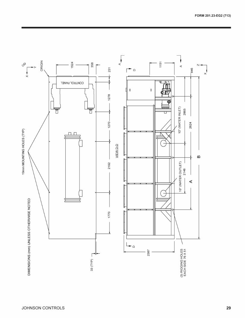
YCIV0630E/V,YCIV0650S/P,YCIV0700E/VandYCIV0720S/P
YCIV A B06307E/V 2238 69600650S/P 2032 58420700E/V 2238 69600720S/P 2238 6960
JOHNSON CONTROLS
FORM 201.23-EG2 (713)
29

JOHNSON CONTROLS30
FORM 201.23-EG2 (713)Dimensions
Notes:1. Placement on a level surface free of obstructions (including snow, for winter operation) or air recirculation ensures rated performance, reliable operation, and ease of maintenance. Site restrictions may compromise minimum clearances indicated below, resulting in unpre-dictable air patters and possible diminished performance. Johnson Controls’ unit controls will optimize the operation without nuisance high pressure safety cutouts; however, the system designer MUST consider potential performance degradation.
Access to the unit control center stipulates the unit is no higher than on spring isolators. Recommended minimum clearances: side to wall - 2m; rear to wall - 2m; control panel end to wall - 1.2m; top - no obstructions whatsoever; distance between adjacent units - 10’. No more than one adjacent wall may be higher than the unit.
YCIV A B C D0760E/V 518 714 2174 28520770S/P 564 660 2009 28780890S/P 564 660 2009 2878
YCIV0760E/V,YCIV0770S/P,andYCIV0890S/P

JOHNSON CONTROLS
FORM 201.23-EG2 (713)
31

JOHNSON CONTROLS32
FORM 201.23-EG2 (713)Dimensions
Notes:1. Placement on a level surface free of obstructions (including snow, for winter operation) or air recirculation ensures rated performance, reliable operation, and ease of maintenance. Site restrictions may compromise minimum clearances indicated below, resulting in unpre-dictable air patters and possible diminished performance. Johnson Controls’ unit controls will optimize the operation without nuisance high pressure safety cutouts; however, the system designer MUST consider potential performance degradation.
Access to the unit control center stipulates the unit is no higher than on spring isolators. Recommended minimum clearances: side to wall - 2m; rear to wall - 2m; control panel end to wall - 1.2m; top - no obstructions whatsoever; distance between adjacent units - 10’. No more than one adjacent wall may be higher than the unit.
YCIV0800E/VandYCIV0830E/V

JOHNSON CONTROLS
FORM 201.23-EG2 (713)
33

JOHNSON CONTROLS34
FORM 201.23-EG2 (713)Dimensions
Notes:1. Placement on a level surface free of obstructions (including snow, for winter operation) or air recirculation ensures rated performance, reliable operation, and ease of maintenance. Site restrictions may compromise minimum clearances indicated below, resulting in unpre-dictable air patters and possible diminished performance. Johnson Controls’ unit controls will optimize the operation without nuisance high pressure safety cutouts; however, the system designer MUST consider potential performance degradation.
Access to the unit control center stipulates the unit is no higher than on spring isolators. Recommended minimum clearances: side to wall - 2m; rear to wall - 2m; control panel end to wall - 1.2m; top - no obstructions whatsoever; distance between adjacent units - 10’. No more than one adjacent wall may be higher than the unit.
YCIV0920S/P,YCIV0930E/V,andYCIV1000S/P

JOHNSON CONTROLS
FORM 201.23-EG2 (713)
35

JOHNSON CONTROLS36
FORM 201.23-EG2 (713)Dimensions
Notes:1. Placement on a level surface free of obstructions (including snow, for winter operation) or air recirculation ensures rated performance, reliable operation, and ease of maintenance. Site restrictions may compromise minimum clearances indicated below, resulting in unpre-dictable air patters and possible diminished performance. Johnson Controls’ unit controls will optimize the operation without nuisance high pressure safety cutouts; however, the system designer MUST consider potential performance degradation.
Access to the unit control center stipulates the unit is no higher than on spring isolators. Recommended minimum clearances: side to wall - 2m; rear to wall - 2m; control panel end to wall - 1.2m; top - no obstructions whatsoever; distance between adjacent units - 10’. No more than one adjacent wall may be higher than the unit.
YCIV1050E/VandYCIV1070S/P

JOHNSON CONTROLS
FORM 201.23-EG2 (713)
37

JOHNSON CONTROLS38
FORM 201.23-EG2 (713)Dimensions
Notes:1. Placement on a level surface free of obstructions (including snow, for winter operation) or air recirculation ensures rated performance, reliable operation, and ease of maintenance. Site restrictions may compromise minimum clearances indicated below, resulting in unpre-dictable air patters and possible diminished performance. Johnson Controls’ unit controls will optimize the operation without nuisance high pressure safety cutouts; however, the system designer MUST consider potential performance degradation.
Access to the unit control center stipulates the unit is no higher than on spring isolators. Recommended minimum clearances: side to wall - 2m; rear to wall - 2m; control panel end to wall - 1.2m; top - no obstructions whatsoever; distance between adjacent units - 10’. No more than one adjacent wall may be higher than the unit.
YCIV1120E/V

JOHNSON CONTROLS
FORM 201.23-EG2 (713)
39

JOHNSON CONTROLS40
FORM 201.23-EG2 (713)Dimensions
Notes:1. Placement on a level surface free of obstructions (including snow, for winter operation) or air recirculation ensures rated performance, reliable operation, and ease of maintenance. Site restrictions may compromise minimum clearances indicated below, resulting in unpre-dictable air patters and possible diminished performance. Johnson Controls’ unit controls will optimize the operation without nuisance high pressure safety cutouts; however, the system designer MUST consider potential performance degradation.
Access to the unit control center stipulates the unit is no higher than on spring isolators. Recommended minimum clearances: side to wall - 2m; rear to wall - 2m; control panel end to wall - 1.2m; top - no obstructions whatsoever; distance between adjacent units - 10’. No more than one adjacent wall may be higher than the unit.
YCIV1180S/P

JOHNSON CONTROLS
FORM 201.23-EG2 (713)
41

JOHNSON CONTROLS42
FORM 201.23-EG2 (713)Dimensions
Notes:1. Placement on a level surface free of obstructions (including snow, for winter operation) or air recirculation ensures rated performance, reliable operation, and ease of maintenance. Site restrictions may compromise minimum clearances indicated below, resulting in unpre-dictable air patters and possible diminished performance. Johnson Controls’ unit controls will optimize the operation without nuisance high pressure safety cutouts; however, the system designer MUST consider potential performance degradation.
Access to the unit control center stipulates the unit is no higher than on spring isolators. Recommended minimum clearances: side to wall - 2m; rear to wall - 2m; control panel end to wall - 1.2m; top - no obstructions whatsoever; distance between adjacent units - 10’. No more than one adjacent wall may be higher than the unit.
YCIV1220E/VandYCIV1340S/P

JOHNSON CONTROLS
FORM 201.23-EG2 (713)
43
JOHNSON CONTROLS44
FORM 201.23-EG2 (713)Dimensions
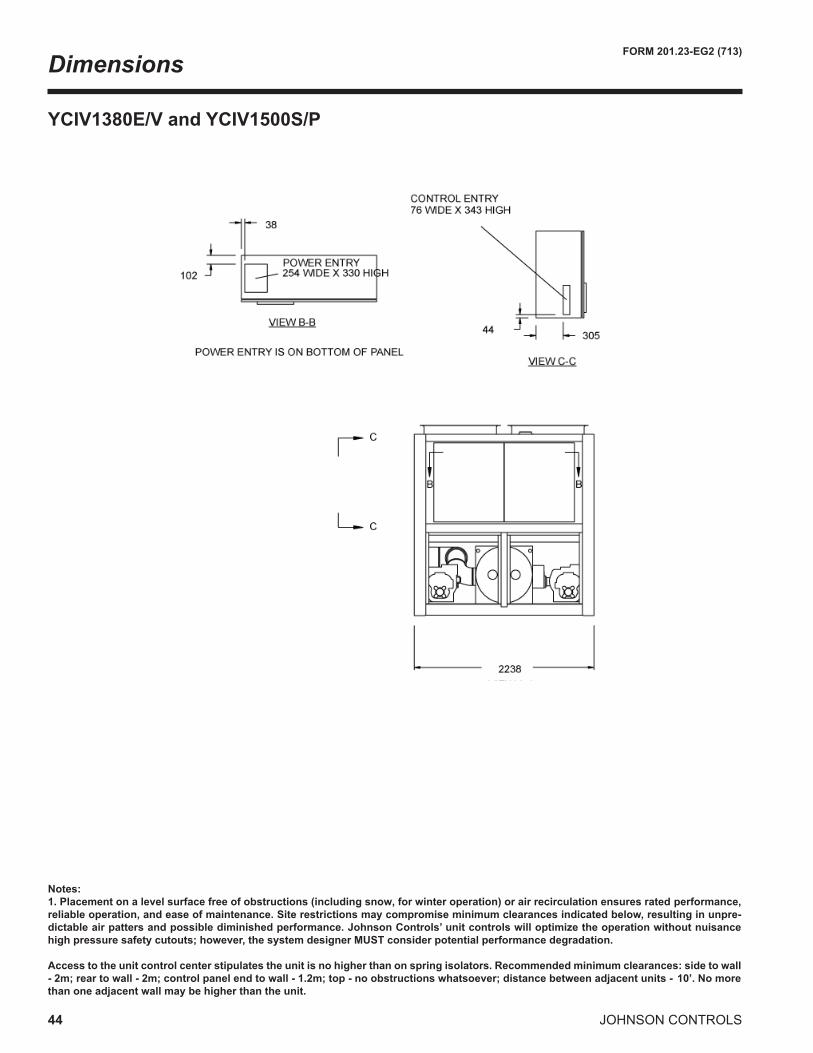
Notes:1. Placement on a level surface free of obstructions (including snow, for winter operation) or air recirculation ensures rated performance, reliable operation, and ease of maintenance. Site restrictions may compromise minimum clearances indicated below, resulting in unpre-dictable air patters and possible diminished performance. Johnson Controls’ unit controls will optimize the operation without nuisance high pressure safety cutouts; however, the system designer MUST consider potential performance degradation.
Access to the unit control center stipulates the unit is no higher than on spring isolators. Recommended minimum clearances: side to wall - 2m; rear to wall - 2m; control panel end to wall - 1.2m; top - no obstructions whatsoever; distance between adjacent units - 10’. No more than one adjacent wall may be higher than the unit.
YCIV1380E/VandYCIV1500S/P

JOHNSON CONTROLS
FORM 201.23-EG2 (713)
45

JOHNSON CONTROLS46
FORM 201.23-EG2 (713)Dimensions
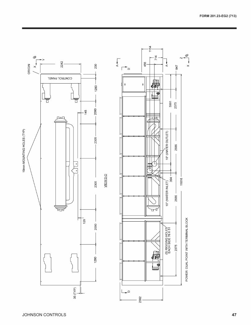
Models YCIV1649P
Notes:1. Placement on a level surface free of obstructions (including snow, for winter operation) or air recirculation ensures rated performance, reliable operation, and ease of maintenance. Site restrictions may compromise minimum clearances indicated below, resulting in unpre-dictable air patters and possible diminished performance. Johnson Controls’ unit controls will optimize the operation without nuisance high pressure safety cutouts; however, the system designer MUST consider potential performance degradation.
Access to the unit control center stipulates the unit is no higher than on spring isolators. Recommended minimum clearances: side to wall - 2m; rear to wall - 2m; control panel end to wall - 1.2m; top - no obstructions whatsoever; distance between adjacent units - 10’. No more than one adjacent wall may be higher than the unit.
JOHNSON CONTROLS
FORM 201.23-EG2 (713)
47

JOHNSON CONTROLS48
FORM 201.23-EG2 (713)
CO
NTR
OL
PAN
EL
L1 L2
R6R1
L6L5L4L3
R2 R3 R4 R5 R7
L7
x
y
Isolator Locations
STANDARD EFFICIENCY - SIMODEL YCIV ISOLATORLOCATIONS(X,Y)-MMANDPOINTLOADS-KG
50 HZ 1 2 3 4 5 6 7
0600S/P
LEFT - L ( 230 , 2204 ) ( 1510 , 2204 ) ( 2780 , 2204 ) ( 5360 , 2204 ) AL FIN COILS 772 722 633 608CU FIN COILS 772 773 789 763
RS&LS1 / AL FIN COILS 853 803 633 608RS&LS1 / CU FIN COILS 853 854 789 763
RIGHT - R ( 230 , 32 ) ( 1510 , 32 ) ( 2780 , 32 ) ( 5360 , 32 ) AL FIN COILS 772 722 633 608CU FIN COILS 772 773 789 763
RS&LS1 / AL FIN COILS 853 803 633 608RS&LS1 / CU FIN COILS 853 854 789 763
0650S/P
LEFT - L ( 230 , 2204 ) ( 1510 , 2204 ) ( 2780 , 2204 ) ( 5360 , 2204 ) AL FIN COILS 780 732 756 730CU FIN COILS 780 783 912 885
RS&LS1 / AL FIN COILS 861 813 756 730RS&LS1 / CU FIN COILS 861 864 912 885
RIGHT - R ( 230 , 32 ) ( 1510 , 32 ) ( 2780 , 32 ) ( 5360 , 32 ) AL FIN COILS 772 723 756 730CU FIN COILS 772 774 912 885
RS&LS1 / AL FIN COILS 853 804 756 730RS&LS1 / CU FIN COILS 853 855 912 885
0720S/P
LEFT - L ( 230 , 2204 ) ( 1510 , 2204 ) ( 2780 , 2204 ) ( 4970 , 2204 ) ( 6740 , 2204 ) AL FIN COILS 778 716 707 578 351CU FIN COILS 778 771 861 750 424
RS&LS1 / AL FIN COILS 859 797 707 578 351RS&LS1 / CU FIN COILS 859 852 861 750 424
RIGHT - R ( 230 , 32 ) ( 1510 , 32 ) ( 2780 , 32 ) ( 4970 , 32 ) ( 6740 , 32 ) AL FIN COILS 770 707 707 563 301CU FIN COILS 770 762 861 735 374
RS&LS1 / AL FIN COILS 851 788 707 563 301RS&LS1 / CU FIN COILS 851 843 861 735 374
0770S/P
LEFT - L ( 230 , 2204 ) ( 1510 , 2204 ) ( 2780 , 2204 ) ( 4970 , 2204 ) ( 6740 , 2204 ) AL FIN COILS 784 762 802 686 415CU FIN COILS 784 817 956 858 488
RS&LS1 / AL FIN COILS 865 843 802 686 415RS&LS1 / CU FIN COILS 865 898 956 858 488
RIGHT - R ( 230 , 32 ) ( 1510 , 32 ) ( 2780 , 32 ) ( 4970 , 32 ) ( 6740 , 32 ) AL FIN COILS 784 760 800 669 363CU FIN COILS 784 815 956 841 436
RS&LS1 / AL FIN COILS 865 841 800 669 363RS&LS1 / CU FIN COILS 865 896 954 841 436
0840S/P
LEFT - L ( 230 , 2204 ) ( 1510 , 2204 ) ( 2780 , 2204 ) ( 4970 , 2204 ) ( 6740 , 2204 ) AL FIN COILS 784 762 802 691 435CU FIN COILS 784 817 956 863 508
RS&LS1 / AL FIN COILS 865 843 802 691 435RS&LS1 / CU FIN COILS 865 898 956 863 508
RIGHT - R ( 230 , 32 ) ( 1510 , 32 ) ( 2780 , 32 ) ( 4970 , 32 ) ( 6740 , 32 ) AL FIN COILS 784 760 800 689 433CU FIN COILS 784 815 954 861 506
RS&LS1 / AL FIN COILS 865 841 800 689 433RS&LS1 / CU FIN COILS 865 896 954 861 506

JOHNSON CONTROLS
FORM 201.23-EG2 (713)
49
STANDARD EFFICIENCY - SIMODEL YCIV ISOLATORLOCATIONS(X,Y)-MMANDPOINTLOADS-KG
50 HZ 1 2 3 4 5 6 7
0920S/P
LEFT - L ( 230 , 2204 ) ( 1510 , 2204 ) ( 2470 , 2204 ) ( 4100 , 2204 ) ( 5350 , 2204 ) ( 7820 , 2204 ) AL FIN COILS 784 743 566 526 572 435CU FIN COILS 784 784 675 651 730 544
RS&LS1 / AL FIN COILS 865 824 566 526 572 435RS&LS1 / CU FIN COILS 865 865 675 651 730 544
RIGHT - R ( 230 , 32 ) ( 1510 , 32 ) ( 2470 , 32 ) ( 4100 , 32 ) ( 5350 , 32 ) ( 7820 , 32 ) AL FIN COILS 780 737 562 523 561 433CU FIN COILS 780 778 671 648 719 542
RS&LS1 / AL FIN COILS 861 818 562 523 561 433RS&LS1 / CU FIN COILS 861 859 671 648 721 542
1000S/P
LEFT - L ( 230 , 2204 ) ( 1510 , 2204 ) ( 2470 , 2204 ) ( 4100 , 2204 ) ( 5350 , 2204 ) ( 7820 , 2204 ) AL FIN COILS 784 743 566 526 574 456CU FIN COILS 784 784 675 651 732 565
RS&LS1 / AL FIN COILS 865 824 566 526 574 456RS&LS1 / CU FIN COILS 865 865 675 651 732 565
RIGHT - R ( 230 , 32 ) ( 1510 , 32 ) ( 2470 , 32 ) ( 4100 , 32 ) ( 5350 , 32 ) ( 7820 , 32 ) AL FIN COILS 784 743 566 526 574 456CU FIN COILS 784 784 675 651 732 565
RS&LS1 / AL FIN COILS 865 824 566 526 574 456RS&LS1 / CU FIN COILS 865 865 675 651 734 565
1070S/P
LEFT - L ( 230 , 2204 ) ( 1475 , 2204 ) ( 2823 , 2204 ) ( 5199 , 2204 ) ( 7236 , 2204 ) ( 9346 , 2204 ) AL FIN COILS 795 719 826 821 963 533CU FIN COILS 805 797 982 978 1119 611
RS&LS1 / AL FIN COILS 875 799 826 821 993 663RS&LS1 / CU FIN COILS 855 877 982 978 1149 741
RIGHT - R ( 230 , 32 ) ( 1475 , 32 ) ( 2823 , 32 ) ( 5199 , 32 ) ( 7236 , 32 ) ( 9346 , 32 ) AL FIN COILS 795 724 1092 1095 1195 535CU FIN COILS 805 802 1248 1252 1351 613
RS&LS1 / AL FIN COILS 875 804 1092 1095 1225 665RS&LS1 / CU FIN COILS 885 882 1248 1252 1381 743
1180S/P
LEFT - L ( 230 , 2204 ) ( 1475 , 2204 ) ( 2823 , 2204 ) ( 5199 , 2204 ) ( 7236 , 2204 ) ( 9346 , 2204 ) AL FIN COILS 795 719 886 897 1045 537CU FIN COILS 805 797 1042 1054 1201 615
RS&LS1 / AL FIN COILS 875 799 886 897 1075 667RS&LS1 / CU FIN COILS 885 877 1042 1054 1231 745
RIGHT - R ( 230 , 32 ) ( 1475 , 32 ) ( 2823 , 32 ) ( 5199 , 32 ) ( 7236 , 32 ) ( 9346 , 32 ) AL FIN COILS 795 724 1152 1194 1314 539CU FIN COILS 805 802 1308 1351 1470 607
RS&LS1 / AL FIN COILS 875 804 1152 1194 1344 669RS&LS1 / CU FIN COILS 885 882 1308 1351 1500 747
1340S/P
LEFT - L ( 230 , 2204 ) ( 1510 , 2204 ) ( 2780 , 2204 ) ( 4710 , 2204 ) ( 7225 , 2204 ) ( 9105 , 2204 ) ( 10463 , 2204 ) AL FIN COILS 795 719 886 897 886 517 429CU FIN COILS 805 786 1015 1072 1061 646 483
RS&LS1 / AL FIN COILS 875 799 886 897 886 597 509RS&LS1 / CU FIN COILS 885 866 1015 1072 1061 726 563
RIGHT - R ( 230 , 32 ) ( 1510 , 32 ) ( 2780 , 32 ) ( 4710 , 32 ) ( 7225 , 32 ) ( 9105 , 32 ) ( 10463 , 32 ) AL FIN COILS 795 724 1152 1194 1152 522 429CU FIN COILS 805 778 1281 1369 1327 651 483
RS&LS1 / AL FIN COILS 875 804 1152 1194 1152 602 509RS&LS1 / CU FIN COILS 885 858 1281 1369 1327 731 563
1500S/P
LEFT - L ( 230 , 2204 ) ( 1510 , 2204 ) ( 2780 , 2204 ) ( 4710 , 2204 ) ( 7572 , 2204 ) ( 9530 , 2204 ) ( 11582 , 2204 ) AL FIN COILS 801 729 886 897 926 637 479CU FIN COILS 811 796 1015 1072 1101 766 533
RS&LS1 / AL FIN COILS 881 809 886 897 926 717 559RS&LS1 / CU FIN COILS 891 876 1015 1072 1101 846 613
RIGHT - R ( 230 , 32 ) ( 1510 , 32 ) ( 2780 , 32 ) ( 4710 , 32 ) ( 7572 , 32 ) ( 9530 , 32 ) ( 11582 , 32 ) AL FIN COILS 801 734 1152 1194 1192 642 479CU FIN COILS 811 788 1281 1369 1367 771 533
RS&LS1 / AL FIN COILS 881 814 1152 1194 1192 722 559RS&LS1 / CU FIN COILS 891 868 1281 1369 1367 851 613
1649P
LEFT - L (230 , 2207) (1510 , 2207) (3600 , 2207) (5905 , 2207) (8211 , 2207) (10301 , 2207) (11581 , 2207)AL FIN COILS 813 523 1395 1389 1382 1221 454CU FIN COILS 779 629 1618 1618 1610 1411 509
RS&LS1/AL FIN COILS 828 485 1525 1516 1509 1274 433RS&LS1/CU FIN COILS 794 590 1748 1745 1737 1463 489
RIGHT - R (230 , 35) (1510 , 35) (3600 , 35) (5905 , 35) (8211 , 35) (10301 , 35) (11581 , 35)AL FIN COILS 813 523 1395 1389 1382 1221 454CU FIN COILS 779 629 1618 1618 1610 1411 509
RS&LS1/AL FIN COILS 828 485 1525 1516 1509 1274 433RS&LS1/CU FIN COILS 794 590 1748 1745 1737 1463 489

JOHNSON CONTROLS50
FORM 201.23-EG2 (713)Isolator Locations - SI
HIGH EFFICIENCY - SIMODEL YCIV ISOLATORLOCATIONS(X,Y)-MMANDPOINTLOADS-KG
50 HZ 1 2 3 4 5 6 7
0590E/V
LEFT - L ( 230 , 2204 ) ( 1510 , 2204 ) ( 2780 , 2204 ) ( 5360 , 2204 ) AL FIN COILS 772 723 756 730CU FIN COILS 772 774 912 885
RS&LS1 / AL FIN COILS 853 804 756 730RS&LS1 / CU FIN COILS 853 855 912 885
RIGHT - R ( 230 , 32 ) ( 1510 , 32 ) ( 2780 , 32 ) ( 5360 , 32 ) AL FIN COILS 772 723 756 730CU FIN COILS 772 774 912 885
RS&LS1 / AL FIN COILS 853 804 756 730RS&LS1 / CU FIN COILS 853 855 912 885
0630E/V
LEFT - L ( 230 , 2204 ) ( 1510 , 2204 ) ( 2780 , 2204 ) ( 4970 , 2204 ) ( 6740 , 2204 ) AL FIN COILS 770 707 707 578 351CU FIN COILS 770 762 861 750 424
RS&LS1 / AL FIN COILS 851 788 707 578 351RS&LS1 / CU FIN COILS 851 843 861 750 424
RIGHT - R ( 230 , 32 ) ( 1510 , 32 ) ( 2780 , 32 ) ( 4970 , 32 ) ( 6740 , 32 ) AL FIN COILS 770 707 707 563 301CU FIN COILS 770 762 861 735 374
RS&LS1 / AL FIN COILS 851 788 707 563 301RS&LS1 / CU FIN COILS 851 843 861 735 374
0700E/V
LEFT - L ( 230 , 2204 ) ( 1510 , 2204 ) ( 2780 , 2204 ) ( 4970 , 2204 ) ( 6740 , 2204 ) AL FIN COILS 778 717 760 584 372CU FIN COILS 778 772 914 756 445
RS&LS1 / AL FIN COILS 859 798 760 584 372RS&LS1 / CU FIN COILS 859 853 914 756 445
RIGHT - R ( 230 , 32 ) ( 1510 , 32 ) ( 2780 , 32 ) ( 4970 , 32 ) ( 6740 , 32 ) AL FIN COILS 770 708 708 584 372CU FIN COILS 770 763 862 756 445
RS&LS1 / AL FIN COILS 851 789 708 584 372RS&LS1 / CU FIN COILS 851 844 862 756 445
0760E/V
LEFT - L ( 230 , 2204 ) ( 1510 , 2204 ) ( 2780 , 2204 ) ( 4970 , 2204 ) ( 6740 , 2204 ) AL FIN COILS 780 730 734 614 390CU FIN COILS 780 785 888 786 463
RS&LS1 / AL FIN COILS 861 811 734 614 390RS&LS1 / CU FIN COILS 861 866 888 786 463
RIGHT - R ( 230 , 32 ) ( 1510 , 32 ) ( 2780 , 32 ) ( 4970 , 32 ) ( 6740 , 32 ) AL FIN COILS 780 730 734 614 390CU FIN COILS 780 785 888 786 463
RS&LS1 / AL FIN COILS 861 811 734 614 390RS&LS1 / CU FIN COILS 861 866 888 786 463
0800E/V
LEFT - L ( 230 , 2204 ) ( 1510 , 2204 ) ( 2470 , 2204 ) ( 4100 , 2204 ) ( 5350 , 2204 ) ( 7820 , 2204 ) AL FIN COILS 780 732 491 451 496 432CU FIN COILS 780 773 600 576 654 541
RS&LS1 / AL FIN COILS 861 813 491 451 496 432RS&LS1 / CU FIN COILS 861 854 600 576 654 541
RIGHT - R ( 230 , 32 ) ( 1510 , 32 ) ( 2470 , 32 ) ( 4100 , 32 ) ( 5350 , 32 ) ( 7820 , 32 ) AL FIN COILS 780 732 491 451 489 433CU FIN COILS 780 773 600 576 647 542
RS&LS1 / AL FIN COILS 861 813 491 451 489 433RS&LS1 / CU FIN COILS 861 854 600 576 649 542
CO
NTR
OL
PAN
EL
L1 L2
R6R1
L6L5L4L3
R2 R3 R4 R5 R7
L7
x
y

JOHNSON CONTROLS
FORM 201.23-EG2 (713)
51
HIGH EFFICIENCY - SIMODEL YCIV ISOLATORLOCATIONS(X,Y)-MMANDPOINTLOADS-KG
50 HZ 1 2 3 4 5 6 7
0830E/V
LEFT - L ( 230 , 2204 ) ( 1510 , 2204 ) ( 2470 , 2204 ) ( 4100 , 2204 ) ( 5350 , 2204 ) ( 7820 , 2204 ) AL FIN COILS 780 733 492 453 500 455CU FIN COILS 780 774 601 578 658 564
RS&LS1 / AL FIN COILS 861 814 492 453 500 455RS&LS1 / CU FIN COILS 861 855 601 578 658 564
RIGHT - R ( 230 , 32 ) ( 1510 , 32 ) ( 2470 , 32 ) ( 4100 , 32 ) ( 5350 , 32 ) ( 7820 , 32 ) AL FIN COILS 780 733 492 453 500 455CU FIN COILS 780 774 601 578 658 564
RS&LS1 / AL FIN COILS 861 814 492 453 500 455RS&LS1 / CU FIN COILS 861 855 601 578 660 564
0930E/V
LEFT - L ( 230 , 2204 ) ( 1510 , 2204 ) ( 2470 , 2204 ) ( 4100 , 2204 ) ( 5350 , 2204 ) ( 7820 , 2204 ) AL FIN COILS 784 743 566 526 574 456CU FIN COILS 784 784 675 651 732 565
RS&LS1 / AL FIN COILS 865 824 566 526 574 456RS&LS1 / CU FIN COILS 865 865 675 651 732 565
RIGHT - R ( 230 , 32 ) ( 1510 , 32 ) ( 2470 , 32 ) ( 4100 , 32 ) ( 5350 , 32 ) ( 7820 , 32 ) AL FIN COILS 780 739 566 526 574 456CU FIN COILS 780 780 675 651 732 565
RS&LS1 / AL FIN COILS 861 820 566 526 574 456RS&LS1 / CU FIN COILS 861 861 675 651 734 565
1050E/V
LEFT - L ( 230 , 2204 ) ( 1475 , 2204 ) ( 2823 , 2204 ) ( 5199 , 2204 ) ( 7236 , 2204 ) ( 9346 , 2204 ) AL FIN COILS 795 719 826 834 981 533CU FIN COILS 805 797 982 991 1137 611
RS&LS1 / AL FIN COILS 875 799 826 834 1011 633RS&LS1 / CU FIN COILS 885 877 982 991 1167 741
RIGHT - R ( 230 , 32 ) ( 1475 , 32 ) ( 2823 , 32 ) ( 5199 , 32 ) ( 7236 , 32 ) ( 9346 , 32 ) AL FIN COILS 795 724 1092 1131 1250 535CU FIN COILS 805 802 1248 1288 1406 613
RS&LS1 / AL FIN COILS 875 804 1092 1131 1280 665RS&LS1 / CU FIN COILS 885 882 1248 1288 1436 743
1120E/V
LEFT - L ( 230 , 2204 ) ( 1510 , 2204 ) ( 2780 , 2204 ) ( 4710 , 2204 ) ( 7225 , 2204 ) ( 9105 , 2204 ) ( 10463 , 2204 ) AL FIN COILS 795 719 838 848 714 476 421CU FIN COILS 805 786 967 1023 889 605 475
RS&LS1 / AL FIN COILS 875 799 838 848 714 556 501RS&LS1 / CU FIN COILS 855 866 967 1023 889 685 555
RIGHT - R ( 230 , 32 ) ( 1510 , 32 ) ( 2780 , 32 ) ( 4710 , 32 ) ( 7225 , 32 ) ( 9105 , 32 ) ( 10463 , 32 ) AL FIN COILS 795 724 1104 1145 1063 508 421CU FIN COILS 805 778 1233 1320 1238 637 475
RS&LS1 / AL FIN COILS 875 804 1104 1145 1063 588 501RS&LS1 / CU FIN COILS 885 858 1233 1320 1238 717 555
1220E/V
LEFT - L ( 230 , 2204 ) ( 1510 , 2204 ) ( 2780 , 2204 ) ( 4710 , 2204 ) ( 7225 , 2204 ) ( 9105 , 2204 ) ( 10463 , 2204 ) AL FIN COILS 795 719 886 897 886 517 421CU FIN COILS 805 786 1015 1072 1061 646 475
RS&LS1 / AL FIN COILS 875 799 886 897 886 597 501RS&LS1 / CU FIN COILS 885 876 1015 1072 1061 726 555
RIGHT - R ( 230 , 32 ) ( 1510 , 32 ) ( 2780 , 32 ) ( 4710 , 32 ) ( 7225 , 32 ) ( 9105 , 32 ) ( 10463 , 32 ) AL FIN COILS 795 724 1152 1194 1152 522 421CU FIN COILS 805 778 1281 1369 1327 651 475
RS&LS1 / AL FIN COILS 875 804 1152 1194 1152 602 501RS&LS1 / CU FIN COILS 885 858 1281 1369 1327 731 555
1380E/V
LEFT - L ( 230 , 2204 ) ( 1510 , 2204 ) ( 2780 , 2204 ) ( 4710 , 2204 ) ( 7572 , 2204 ) ( 9530 , 2204 ) ( 11582 , 2204 ) AL FIN COILS 801 729 886 897 926 637 471CU FIN COILS 811 796 1015 1072 1101 766 525
RS&LS1 / AL FIN COILS 881 809 886 897 926 717 551RS&LS1 / CU FIN COILS 891 876 1015 1072 1101 846 605
RIGHT - R ( 230 , 32 ) ( 1510 , 32 ) ( 2780 , 32 ) ( 4710 , 32 ) ( 7572 , 32 ) ( 9530 , 32 ) ( 11582 , 32 ) AL FIN COILS 801 734 1152 1194 1192 642 471CU FIN COILS 811 788 1281 1369 1367 771 525
RS&LS1 / AL FIN COILS 881 814 1152 1194 1192 722 551RS&LS1 / CU FIN COILS 891 868 1281 1369 1367 851 605

JOHNSON CONTROLS52
FORM 201.23-EG2 (713)Isolator Details
ONE INCH DEFLECTION SPRING ISOLATOR CROSS-REFERENCE
CPX-X-
����
������
��
��
�������������������������� ��
MODEL NUMBER COLOR CODE
RATED CAPACITY (FOR UNITS WITH ALL LOAD POINTS LESS THAN 1785 LBS (810 KG)
(LBS.) (KG)
CP-1D-510 BLACK UP THRU 434 UP THRU 197CP-1D-900 DARK GREEN 435 THRU 765 198 THRU 347
CP-1D-1200 GRAY 766 THRU 1020 348 THRU 463CP-1D-1360 WHITE 1021 THRU 1156 464 THRU 524
CP-1D-1785N GRAY/RED 1157 THRU 1785 525 THRU 810
MODEL NUMBER COLOR CODE
RATED CAPACITY (FOR UNITS WITH ANY LOAD POINT ABOVE 1518 LBS (689 KG)
(LBS.) (KG)
C2P-1D-1350 DARK PURPLE UP THRU 1148 UP TO 521C2P-1D-1800 DARK GREEN 1149 THRU 1530 522 - 694C2P-1D-2400 GRAY 1531 THRU 2040 695 - 925C2P-1D-2400 GRAY 1531 THRU 2040 695 - 925C2P-1D-2720 WHITE 2041 THRU 2312 926 - 1049
C2P-1D-3570N GRAY/RED 2313 THRU 3570 1050 - 1619
MOUNTTYPE
DIMENSION DATA (INCHES)
W D L B C T H
CP 3 5/8 7-3/4 6-1/2 4-3/4 1/2 5-5/8
C2P 3 5/8 10-1/2 9-1/4 7-3/4 9/16 6
Note:Donotmixisolatorstypes

JOHNSON CONTROLS
FORM 201.23-EG2 (713)
53
ELASTOMERIC ISOLATOR CROSS-REFERENCE
LD17304
CDCD
HFHF
BT
BT
ALL
ALL
W
W
DWDW
MOLDEDDURULENEMOLDED
DURULENE
R = 0.280 SlotTyp 2 Places
Ø = AD ThruTyp 2 Places
RD-Style Isolators
MOUNTTYPE
DIMENSION DATA (INCHES)
L W HF AL AD BT CD DW
RD1-WR 3.13 1.75 1.25 2.38 0.34 0.19 5/16-18UNCX3/4 1.25
RD2-WR 3.88 2.38 1.75 3.00 0.34 0.22 3/8-16UNCX1 1.75
RD3-WR 5.50 3.38 2.88 4.13 0.56 0.25 1/2-13UNCX1 2.50
RD4-WR 6.25 4.63 2.75 5.00 0.56 0.38 1/2-13UNCX1 3.00
MODEL NUMBER ISOLATOR COLOR WEIGHT RANGE (LBS) WEIGHT RANGE (KGS)RD-3-CHARCOAL-WR CHARCOAL UP THRU 825 UP TO 374RD-4-BRICK RED-WR BRICK RED 826 THRU 1688 375 - 766RD-4-CHARCOAL-WR CHARCOAL 1689 THRU 4000 767 - 1814
Note:Donotmixisolatorstypes

JOHNSON CONTROLS54
FORM 201.23-EG2 (713)Isolator Details
TWO INCH DEFLECTION, SEISMIC SPRING ISOLATOR CROSS-REFERENCE
Y2RS
3/4”
7/8”
3/8” GAP
3/4”TYP. (4)
5/8” 2-3/4”
1-1/8”
2-3/4”
8P
4
8
STOP &8-3/8”OPER.HEIGHT
4
4
MODEL NUMBER ISOL. COLOR WEIGHT RANGE (LBS) WEIGHT RANGE (KGS)Y2RSI-2D-460 GREEN UP THRU 391 UP TO 177Y2RSI-2D-710 DARK BROWN 392 THRU 604 178 - 274Y2RSI-2D-870 RED 605 THRU 740 275 - 336
Y2RSI-2D-1200N RED/BLACK 741 THRU 1020 337 - 463Y2RSI-2D-1690 PINK 1021 THRU 1437 464 - 652
Y2RSI-2D-2640N PINK/GRAY 1438 THRU 2244 653 - 1018Y2RSI-2D-2870N PINK/GRAY/ORANGE 2245 THRU 2618 1019 - 1188Y2RSI-2D-3280N PINK/GRAY/DK.BROWN 2619 THRU 3740 1189 - 1696
Note:Donotmixisolatorstypes
MODEL Y2RSI-2D SEISMICALLY RESTRAINED VIBRATION ISOLATOR FOR 2" DEFLECTION

JOHNSON CONTROLS
FORM 201.23-EG2 (713)
55
INTENTIONALLYLEFTBLANK

JOHNSON CONTROLS56
FORM 201.23-EG2 (713)Electrical Data - 2 Comp Standard Efficiency
STANDARDEFFICIENCYYCIV____S/P STANDARDEFFICIENCYYCIV____S/P
MODELNO./NAMEPLATESYSTEM 1 SYSTEM 2
STD. & ULTRA QUIET COND. FANS HIGHHEAD/STATICCOND.FANS TWO-SPEED COND. FANS STD. & ULTRA QUIET COND. FANS HIGHHEAD/STATICCOND.FANS TWO-SPEED COND. FANS
YCIVS/P INPUT VOLTS (9)
INPUT FREQ
COMPRES-SOR
RLA (5)
CONDENSER FANS COMPRES-SOR CONDENSER FANS COMPRES-
SORRLA (5)
CONDENSER FANS COMPRES-SOR
RLA (5)
CONDENSER FANS COMPRES-SOR
RLA (5)
CONDENSER FANS COMPRES-SOR
RLA (5)
CONDENSER FANS
QTY. FLA (EA) RLA (5) QTY. FLA (EA) QTY. FLA (EA) QTY. FLA (EA) QTY. FLA (EA) QTY. FLA (EA)
0600 400 50 144 4 3.1 144 4 9.3 152 4 3.8 144 4 3.1 144 4 9.3 152 4 3.80650 400 50 191 4 3.1 191 4 9.3 198 4 3.8 127 4 3.1 127 4 9.3 132 4 3.80720 400 50 195 5 3.1 195 5 9.3 207 5 3.8 144 4 3.1 144 4 9.3 152 4 3.80770 400 50 174 5 3.1 174 5 9.3 185 5 3.8 195 4 3.1 195 4 9.3 201 4 3.80840 400 50 194 5 3.1 194 5 9.3 206 5 3.8 194 5 3.1 194 5 9.3 206 5 3.80920 400 50 232 6 3.1 232 6 9.3 246 6 3.8 192 5 3.1 192 5 9.3 204 5 3.81000 400 50 230 6 3.1 230 6 9.3 243 6 3.8 230 6 3.1 230 6 9.3 243 6 3.8
YCIVS/P CONTROLKVA (7)
UNIT SHORT CIRCUIT WITH-STAND (KA)
FIELD WIRING & PROTECTIONSTD. & ULTRA QUIET COND. FANS HIGHHEAD/HIGHSTATICFANS TWO-SPEED COND. FANS
TERMINAL BLOCK (STD)
CIRCUIT BREAKER (OPT)
MINIMUM CKT. AMPACITY (MCA) (3)
RECOMMENDED FUSE/CKT.
BREAKER RAT-ING (4)
MAX.INVERSETIME CKT.
BRKR. RATING (2)
MAXDUALELEMENT FUSE
SIZE (2)
MINIMUM CKT. AMPACITY (MCA) (3)
RECOMMENDED FUSE/CKT.
BREAKER RAT-ING (4)
MAX.INVERSETIME CKT.
BRKR. RATING (2)
MAXDUALELEMENT FUSE
SIZE (2)
MINIMUM CKT. AMPACITY (MCA) (3)
RECOMMENDED FUSE/CKT.
BREAKER RAT-ING (4)
MAX.INVERSETIME CKT.
BRKR. RATING (2)
MAXDUALELEMENT FUSE
SIZE (2)0600 1.8 30KA 65KA 350 400 450 450 373 450 500 500 399 450 500 5000650 1.8 30KA 65KA 390 450 500 500 410 500 600 600 440 500 600 6000720 1.8 30KA 65KA 416 500 600 600 445 500 600 600 472 600 600 6000770 1.8 30KA 65KA 446 500 600 600 471 600 600 600 502 600 700 7000840 1.8 30KA 65KA 468 600 600 600 502 600 700 700 530 600 700 7000920 1.8 30KA 65KA 517 600 700 700 553 700 800 800 585 700 800 8001000 1.8 30KA 65KA 555 700 700 700 593 700 800 800 629 700 800 800
Seepage64forElectricalDatafootnotes.

JOHNSON CONTROLS
FORM 201.23-EG2 (713)
57
STANDARDEFFICIENCYYCIV____S/P STANDARDEFFICIENCYYCIV____S/P
MODELNO./NAMEPLATESYSTEM 1 SYSTEM 2
STD. & ULTRA QUIET COND. FANS HIGHHEAD/STATICCOND.FANS TWO-SPEED COND. FANS STD. & ULTRA QUIET COND. FANS HIGHHEAD/STATICCOND.FANS TWO-SPEED COND. FANS
YCIVS/P INPUT VOLTS (9)
INPUT FREQ
COMPRES-SOR
RLA (5)
CONDENSER FANS COMPRES-SOR CONDENSER FANS COMPRES-
SORRLA (5)
CONDENSER FANS COMPRES-SOR
RLA (5)
CONDENSER FANS COMPRES-SOR
RLA (5)
CONDENSER FANS COMPRES-SOR
RLA (5)
CONDENSER FANS
QTY. FLA (EA) RLA (5) QTY. FLA (EA) QTY. FLA (EA) QTY. FLA (EA) QTY. FLA (EA) QTY. FLA (EA)
0600 400 50 144 4 3.1 144 4 9.3 152 4 3.8 144 4 3.1 144 4 9.3 152 4 3.80650 400 50 191 4 3.1 191 4 9.3 198 4 3.8 127 4 3.1 127 4 9.3 132 4 3.80720 400 50 195 5 3.1 195 5 9.3 207 5 3.8 144 4 3.1 144 4 9.3 152 4 3.80770 400 50 174 5 3.1 174 5 9.3 185 5 3.8 195 4 3.1 195 4 9.3 201 4 3.80840 400 50 194 5 3.1 194 5 9.3 206 5 3.8 194 5 3.1 194 5 9.3 206 5 3.80920 400 50 232 6 3.1 232 6 9.3 246 6 3.8 192 5 3.1 192 5 9.3 204 5 3.81000 400 50 230 6 3.1 230 6 9.3 243 6 3.8 230 6 3.1 230 6 9.3 243 6 3.8
YCIVS/P CONTROLKVA (7)
UNIT SHORT CIRCUIT WITH-STAND (KA)
FIELD WIRING & PROTECTIONSTD. & ULTRA QUIET COND. FANS HIGHHEAD/HIGHSTATICFANS TWO-SPEED COND. FANS
TERMINAL BLOCK (STD)
CIRCUIT BREAKER (OPT)
MINIMUM CKT. AMPACITY (MCA) (3)
RECOMMENDED FUSE/CKT.
BREAKER RAT-ING (4)
MAX.INVERSETIME CKT.
BRKR. RATING (2)
MAXDUALELEMENT FUSE
SIZE (2)
MINIMUM CKT. AMPACITY (MCA) (3)
RECOMMENDED FUSE/CKT.
BREAKER RAT-ING (4)
MAX.INVERSETIME CKT.
BRKR. RATING (2)
MAXDUALELEMENT FUSE
SIZE (2)
MINIMUM CKT. AMPACITY (MCA) (3)
RECOMMENDED FUSE/CKT.
BREAKER RAT-ING (4)
MAX.INVERSETIME CKT.
BRKR. RATING (2)
MAXDUALELEMENT FUSE
SIZE (2)0600 1.8 30KA 65KA 350 400 450 450 373 450 500 500 399 450 500 5000650 1.8 30KA 65KA 390 450 500 500 410 500 600 600 440 500 600 6000720 1.8 30KA 65KA 416 500 600 600 445 500 600 600 472 600 600 6000770 1.8 30KA 65KA 446 500 600 600 471 600 600 600 502 600 700 7000840 1.8 30KA 65KA 468 600 600 600 502 600 700 700 530 600 700 7000920 1.8 30KA 65KA 517 600 700 700 553 700 800 800 585 700 800 8001000 1.8 30KA 65KA 555 700 700 700 593 700 800 800 629 700 800 800

JOHNSON CONTROLS58
FORM 201.23-EG2 (713)Electrical Data - 2 Comp High Efficiency
HIGHEFFICIENCYYCIV____E/V HIGHEFFICIENCYYCIV____E/V
MODELNO./NAMEPLATESYSTEM 1 SYSTEM 2
STD. & ULTRA QUIET COND. FANS HIGHHEAD/STATICCOND.FANS TWO-SPEED COND. FANS STD. & ULTRA QUIET COND. FANS HIGHHEAD/STATICCOND.FANS TWO-SPEED COND. FANS
YCIVE/V INPUT VOLTS (9)
INPUT FREQ
COMPRES-SOR CONDENSER FANS COMPRES-
SOR CONDENSER FANS COMPRES-SOR CONDENSER FANS COMPRES-
SORCONDENSER
FANSCOMPRES-
SORCONDENSER
FANSCOMPRES-
SORCONDENSER
FANS
RLA (5) QTY. FLA (EA) RLA (5) QTY. FLA (EA) RLA (5) QTY. FLA (EA) RLA (5) QTY. FLA (EA) RLA (5) QTY. FLA (EA) RLA (5) QTY. FLA (EA)
0590 400 50 132 4 3.1 132 4 9.3 138 4 3.8 132 4 3.1 132 4 9.3 138 4 3.80630 400 50 134 5 3.1 134 5 9.3 139 5 3.8 146 4 3.1 146 4 9.3 154 4 3.80700 400 50 185 5 3.1 185 5 9.3 196 5 3.8 126 5 3.1 126 5 9.3 131 5 3.80760 400 50 170 5 3.1 170 5 9.3 180 5 3.8 170 5 3.1 170 5 9.3 180 5 3.80800 400 50 170 6 3.1 170 6 9.3 178 6 3.8 183 5 3.1 183 5 9.3 195 5 3.80830 400 50 180 6 3.1 180 6 9.3 189 6 3.8 180 6 3.1 180 6 9.3 189 6 3.80930 400 50 233 6 3.1 233 6 9.3 246 6 3.8 178 6 3.1 178 6 9.3 187 6 3.8
YCIVE/V CONTROLKVA (7)
UNIT SHORT CIRCUIT WITH-STAND (KA)
FIELD WIRING & PROTECTIONSTD. & ULTRA QUIET COND. FANS HIGHHEAD/HIGHSTATICFANS TWO-SPEED COND. FANS
TERMINAL BLOCK (STD)
CIRCUIT BREAKER
(OPT)
MINIMUM CKT. AMPACITY (MCA) (3)
RECOMMENDED FUSE/CKT.BREAKER RATING (4)
MAX.INVERSETIME CKT.
BRKR. RATING (2)
MAXDUALELEMENT FUSE
SIZE (2)
MINIMUM CKT. AMPACITY (MCA) (3)
RECOMMENDED FUSE/CKT.
BREAKER RAT-ING (4)
MAX.INVERSETIME CKT.
BRKR. RATING (2)
MAXDUALELEMENT FUSE
SIZE (2)
MINIMUM CKT. AMPACITY (MCA) (3)
RECOMMENDED FUSE/CKT.
BREAKER RAT-ING (4)
MAX.INVERSETIME CKT.
BRKR. RATING (2)
MAXDUALELEMENT FUSE
SIZE (2)
0590 1.8 30KA 65KA 322 400 450 450 372 450 500 500 342 400 450 4500630 1.8 30KA 65KA 344 400 450 450 400 450 500 500 366 450 500 5000700 1.8 30KA 65KA 388 450 500 500 450 500 600 600 414 500 600 6000760 1.8 30KA 65KA 412 500 500 500 474 600 600 600 442 500 600 6000800 1.8 30KA 65KA 433 500 600 600 501 600 600 600 463 600 600 6000830 1.8 30KA 65KA 443 500 600 600 517 600 700 700 472 600 600 6000930 1.8 30KA 65KA 506 600 700 700 581 700 800 800 541 700 700 700
Seepage64forElectricalDatafootnotes.

JOHNSON CONTROLS
FORM 201.23-EG2 (713)
59
HIGHEFFICIENCYYCIV____E/V HIGHEFFICIENCYYCIV____E/V
MODELNO./NAMEPLATESYSTEM 1 SYSTEM 2
STD. & ULTRA QUIET COND. FANS HIGHHEAD/STATICCOND.FANS TWO-SPEED COND. FANS STD. & ULTRA QUIET COND. FANS HIGHHEAD/STATICCOND.FANS TWO-SPEED COND. FANS
YCIVE/V INPUT VOLTS (9)
INPUT FREQ
COMPRES-SOR CONDENSER FANS COMPRES-
SOR CONDENSER FANS COMPRES-SOR CONDENSER FANS COMPRES-
SORCONDENSER
FANSCOMPRES-
SORCONDENSER
FANSCOMPRES-
SORCONDENSER
FANS
RLA (5) QTY. FLA (EA) RLA (5) QTY. FLA (EA) RLA (5) QTY. FLA (EA) RLA (5) QTY. FLA (EA) RLA (5) QTY. FLA (EA) RLA (5) QTY. FLA (EA)
0590 400 50 132 4 3.1 132 4 9.3 138 4 3.8 132 4 3.1 132 4 9.3 138 4 3.80630 400 50 134 5 3.1 134 5 9.3 139 5 3.8 146 4 3.1 146 4 9.3 154 4 3.80700 400 50 185 5 3.1 185 5 9.3 196 5 3.8 126 5 3.1 126 5 9.3 131 5 3.80760 400 50 170 5 3.1 170 5 9.3 180 5 3.8 170 5 3.1 170 5 9.3 180 5 3.80800 400 50 170 6 3.1 170 6 9.3 178 6 3.8 183 5 3.1 183 5 9.3 195 5 3.80830 400 50 180 6 3.1 180 6 9.3 189 6 3.8 180 6 3.1 180 6 9.3 189 6 3.80930 400 50 233 6 3.1 233 6 9.3 246 6 3.8 178 6 3.1 178 6 9.3 187 6 3.8
YCIVE/V CONTROLKVA (7)
UNIT SHORT CIRCUIT WITH-STAND (KA)
FIELD WIRING & PROTECTIONSTD. & ULTRA QUIET COND. FANS HIGHHEAD/HIGHSTATICFANS TWO-SPEED COND. FANS
TERMINAL BLOCK (STD)
CIRCUIT BREAKER
(OPT)
MINIMUM CKT. AMPACITY (MCA) (3)
RECOMMENDED FUSE/CKT.BREAKER RATING (4)
MAX.INVERSETIME CKT.
BRKR. RATING (2)
MAXDUALELEMENT FUSE
SIZE (2)
MINIMUM CKT. AMPACITY (MCA) (3)
RECOMMENDED FUSE/CKT.
BREAKER RAT-ING (4)
MAX.INVERSETIME CKT.
BRKR. RATING (2)
MAXDUALELEMENT FUSE
SIZE (2)
MINIMUM CKT. AMPACITY (MCA) (3)
RECOMMENDED FUSE/CKT.
BREAKER RAT-ING (4)
MAX.INVERSETIME CKT.
BRKR. RATING (2)
MAXDUALELEMENT FUSE
SIZE (2)
0590 1.8 30KA 65KA 322 400 450 450 372 450 500 500 342 400 450 4500630 1.8 30KA 65KA 344 400 450 450 400 450 500 500 366 450 500 5000700 1.8 30KA 65KA 388 450 500 500 450 500 600 600 414 500 600 6000760 1.8 30KA 65KA 412 500 500 500 474 600 600 600 442 500 600 6000800 1.8 30KA 65KA 433 500 600 600 501 600 600 600 463 600 600 6000830 1.8 30KA 65KA 443 500 600 600 517 600 700 700 472 600 600 6000930 1.8 30KA 65KA 506 600 700 700 581 700 800 800 541 700 700 700

JOHNSON CONTROLS60
FORM 201.23-EG2 (713)Electrical Data - 3 & 4 Comp Standard Efficiency
YCIVS/P CONTROLKVA (7)
UNIT SHORT CIRCUIT WITHSTAND (KA)
FIELD WIRING & PROTECTION FIELD WIRING & PROTECTION FIELD WIRING LUGS
STD. & ULTRA QUIET COND. FANS HIGHHEAD/HIGHSTATICFANS HIGHHEAD/HIGHSTATIC FANS TWO-SPEED COND. FANS STD TERMINAL BLOCK OPT CIRCUIT BREAKER
TERMINAL BLOCK (STD)
CIRCUIT BREAKER (OPT)
MINIMUM CKT.
AMPACITY (MCA) (3)
RECOM.FUSE/CKT. BREAKER
RATING (4)
MAX.INVERSETIME CKT.
BRKR. RATING (2)
MAXDUALELEMENT FUSE
SIZE (2)
MINIMUM CKT. AMPACITY (MCA) (3)
RECOM-MENDEDFUSE/CKT. BREAKER
RATING (4)
MAX.INVERSE TIME CKT.
BRKR. RATING
(2)
MAXDUAL
ELEMENT FUSE SIZE
(2)
MINIMUM CKT.
AMPAC-ITY (MCA)
(3)
RECOM-MENDED FUSE/CKT.
BREAKER RATING
(4)
MAX.INVERSE TIME CKT.
BRKR. RATING (2)
MAXDUALELEMENT FUSE SIZE
(2)
SYSTEMS 1& 3 SYSTEMS 2 & 4 SYSTEMS 1& 3 SYSTEMS 2 & 4
LUGS/PHASE (1)
LUG WIRE RANGE
LUGS/PHASE (1)
LUG WIRE RANGE
LUGS/PHASE
(1)
LUG WIRE RANGE
LUGS/PHASE
(1)
LUG WIRE RANGE
1070 2.4 30KA 65KA 590 700 700 700 671 800 800 800 623 700 800 800 4 #2 - 600 KCM 4 #4/0 - 500 KCM
1180 2.4 30KA 65KA 644 700 800 800 731 800 800 800 683 800 800 800 4 #2 - 600 KCM 4 #4/0 - 500 KCM
1340 2.4 30KA 65KA 724 800 800 800 824 1000 1000 1000 776 1000 1000 1000 4 #2 - 600 KCM 4 #4/0 - 500 KCM
1500 2.4 30KA 65KA 801 1000 1000 1000 913 1000 1000 1000 857 1000 1000 1000 4 #2 - 600 KCM 4 #4/0 - 500 KCM
1649 4 30KA 65KA N/A N/A N/A N/A 537 600 700 700 N/A N/A N/A N/A 3 #2 - 600KCM 3 #2 - 600KCM 4 #2 -400KCM 4 #2 -400KCM
MODELSYSTEM 1 SYSTEM 2 SYSTEM 3 SYSTEM 4
STD. & ULTRA QUIET COND. FANS
HIGHHEAD/STATICCOND. FANS
TWO-SPEED COND. FANS
STD. & ULTRA QUIET COND. FANS
HIGHHEAD/STATICCOND. FANS
TWO-SPEED COND. FANS
STD. & ULTRA QUIET COND. FANS
HIGHHEAD/STATICCOND. FANS
TWO-SPEED COND. FANS
STD & ULTRA QUIET COND FANS
HIGHHEAD/STATICCOND. FANS
TWO-SPEED COND FANS
YCIV S/P
INPUT VOLTS
(9)
INPUT FREQ
COMP. COND. FANS COMP. COND. FANS COMP. COND. FANS COMP. COND. FANS COMP. COND. FANS COMP. COND. FANS COMP. COND. FANS COMP. COND. FANS COMP. COND. FANS COMP COND. FANS COMP. COND. FANS COMP COND. FANS
RLA (5) QTY. FLA (EA) RLA (5) QTY. FLA
(EA) RLA (5) QTY. FLA (EA) RLA (5) QTY. FLA
(EA) RLA (5) QTY. FLA (EA) RLA (5) QTY. FLA
(EA)RLA (5) QTY. FLA
(EA)RLA (5) QTY. FLA
(EA)RLA (5) QTY. FLA
(EA)RLA (5) QTY FLA
(EA)RLA (5) QTY FLA
(EA)RLA (5) QTY. FLA
(EA)1070 400 50 175 5 3.1 175 5 9.3 186 5 3.8 196 4 3.1 196 4 9.3 202 4 3.8 129 4 3.1 129 4 9.3 135 4 3.81180 400 50 177 5 3.1 177 5 9.3 188 5 3.8 177 5 3.1 177 5 9.3 188 5 3.8 198 4 3.1 198 4 9.3 203 4 3.81340 400 50 192 5 3.1 192 5 9.3 204 5 3.8 192 5 3.1 192 5 9.3 204 5 3.8 232 6 3.1 232 6 9.3 245 6 3.81500 400 50 229 6 3.1 229 6 9.3 243 6 3.8 229 6 3.1 229 6 9.3 243 6 3.8 229 6 3.1 229 6 9.3 243 6 3.81649 400 50 N/A N/A N/A 219 6 6 N/A N/A N/A N/A N/A N/A 219 6 6 N/A N/A N/A N/A N/A N/A 209 3 6 N/A N/A N/A N/A N/A N/A 209 3 6 N/A N/A N/A
Seepage64forElectricalDatafootnotes.

JOHNSON CONTROLS
FORM 201.23-EG2 (713)
61
YCIVS/P CONTROLKVA (7)
UNIT SHORT CIRCUIT WITHSTAND (KA)
FIELD WIRING & PROTECTION FIELD WIRING & PROTECTION FIELD WIRING LUGS
STD. & ULTRA QUIET COND. FANS HIGHHEAD/HIGHSTATICFANS HIGHHEAD/HIGHSTATIC FANS TWO-SPEED COND. FANS STD TERMINAL BLOCK OPT CIRCUIT BREAKER
TERMINAL BLOCK (STD)
CIRCUIT BREAKER (OPT)
MINIMUM CKT.
AMPACITY (MCA) (3)
RECOM.FUSE/CKT. BREAKER
RATING (4)
MAX.INVERSETIME CKT.
BRKR. RATING (2)
MAXDUALELEMENT FUSE
SIZE (2)
MINIMUM CKT. AMPACITY (MCA) (3)
RECOM-MENDEDFUSE/CKT. BREAKER
RATING (4)
MAX.INVERSE TIME CKT.
BRKR. RATING
(2)
MAXDUAL
ELEMENT FUSE SIZE
(2)
MINIMUM CKT.
AMPAC-ITY (MCA)
(3)
RECOM-MENDED FUSE/CKT.
BREAKER RATING
(4)
MAX.INVERSE TIME CKT.
BRKR. RATING (2)
MAXDUALELEMENT FUSE SIZE
(2)
SYSTEMS 1& 3 SYSTEMS 2 & 4 SYSTEMS 1& 3 SYSTEMS 2 & 4
LUGS/PHASE (1)
LUG WIRE RANGE
LUGS/PHASE (1)
LUG WIRE RANGE
LUGS/PHASE
(1)
LUG WIRE RANGE
LUGS/PHASE
(1)
LUG WIRE RANGE
1070 2.4 30KA 65KA 590 700 700 700 671 800 800 800 623 700 800 800 4 #2 - 600 KCM 4 #4/0 - 500 KCM
1180 2.4 30KA 65KA 644 700 800 800 731 800 800 800 683 800 800 800 4 #2 - 600 KCM 4 #4/0 - 500 KCM
1340 2.4 30KA 65KA 724 800 800 800 824 1000 1000 1000 776 1000 1000 1000 4 #2 - 600 KCM 4 #4/0 - 500 KCM
1500 2.4 30KA 65KA 801 1000 1000 1000 913 1000 1000 1000 857 1000 1000 1000 4 #2 - 600 KCM 4 #4/0 - 500 KCM
1649 4 30KA 65KA N/A N/A N/A N/A 537 600 700 700 N/A N/A N/A N/A 3 #2 - 600KCM 3 #2 - 600KCM 4 #2 -400KCM 4 #2 -400KCM
MODELSYSTEM 1 SYSTEM 2 SYSTEM 3 SYSTEM 4
STD. & ULTRA QUIET COND. FANS
HIGHHEAD/STATICCOND. FANS
TWO-SPEED COND. FANS
STD. & ULTRA QUIET COND. FANS
HIGHHEAD/STATICCOND. FANS
TWO-SPEED COND. FANS
STD. & ULTRA QUIET COND. FANS
HIGHHEAD/STATICCOND. FANS
TWO-SPEED COND. FANS
STD & ULTRA QUIET COND FANS
HIGHHEAD/STATICCOND. FANS
TWO-SPEED COND FANS
YCIV S/P
INPUT VOLTS
(9)
INPUT FREQ
COMP. COND. FANS COMP. COND. FANS COMP. COND. FANS COMP. COND. FANS COMP. COND. FANS COMP. COND. FANS COMP. COND. FANS COMP. COND. FANS COMP. COND. FANS COMP COND. FANS COMP. COND. FANS COMP COND. FANS
RLA (5) QTY. FLA (EA) RLA (5) QTY. FLA
(EA) RLA (5) QTY. FLA (EA) RLA (5) QTY. FLA
(EA) RLA (5) QTY. FLA (EA) RLA (5) QTY. FLA
(EA)RLA (5) QTY. FLA
(EA)RLA (5) QTY. FLA
(EA)RLA (5) QTY. FLA
(EA)RLA (5) QTY FLA
(EA)RLA (5) QTY FLA
(EA)RLA (5) QTY. FLA
(EA)1070 400 50 175 5 3.1 175 5 9.3 186 5 3.8 196 4 3.1 196 4 9.3 202 4 3.8 129 4 3.1 129 4 9.3 135 4 3.81180 400 50 177 5 3.1 177 5 9.3 188 5 3.8 177 5 3.1 177 5 9.3 188 5 3.8 198 4 3.1 198 4 9.3 203 4 3.81340 400 50 192 5 3.1 192 5 9.3 204 5 3.8 192 5 3.1 192 5 9.3 204 5 3.8 232 6 3.1 232 6 9.3 245 6 3.81500 400 50 229 6 3.1 229 6 9.3 243 6 3.8 229 6 3.1 229 6 9.3 243 6 3.8 229 6 3.1 229 6 9.3 243 6 3.81649 400 50 N/A N/A N/A 219 6 6 N/A N/A N/A N/A N/A N/A 219 6 6 N/A N/A N/A N/A N/A N/A 209 3 6 N/A N/A N/A N/A N/A N/A 209 3 6 N/A N/A N/A

JOHNSON CONTROLS62
FORM 201.23-EG2 (713)Electrical Data - 3 Comp High Efficiency
Seepage64forElectricalDatafootnotes.
MODELNO./NAMEPLATESYSTEM 1 SYSTEM 2 SYSTEM 2 SYSTEM 3
STD. & ULTRA QUIET COND. FANS
HIGHHEAD/STATICCOND.FANS TWO-SPEED COND. FANS STD. & ULTRA QUIET
COND. FANSHIGHHEAD/STATICCOND.
FANS TWO-SPEED COND. FANS STD. & ULTRA QUIET COND. FANS
HIGHHEAD/STATICCOND.FANS TWO-SPEED COND. FANS
YCIVE/VINPUT VOLTS
(9)
INPUT FREQ
COMP. CONDENSER FANS COMP. CONDENSER
FANS COMP. CONDENSER FANS COMP. CONDENSER
FANS COMP. CONDENSER FANS COMP. CONDENSER
FANS COMP.CON-
DENSER FANS
COMP.CON-
DENSER FANS
COMP. CONDENSER FANS
RLA (5) QTY. FLA (EA) RLA (5) QTY. FLA (EA) RLA (5) QTY. FLA (EA) RLA (5) QTY. FLA (EA) RLA (5) QTY. FLA (EA) RLA (5) QTY. FLA (EA) RLA (5) QTY. FLA (EA) RLA (5) QTY. FLA (EA) RLA (5) QTY. FLA (EA)
1050 400 50 170 5 3.1 170 5 9.3 180 5 3.8 170 5 3.1 170 5 9.3 180 5 3.8 126 4 3.1 126 4 9.3 132 4 3.81120 400 50 164 5 3.1 164 5 9.3 173 5 3.8 164 5 3.1 164 5 9.3 173 5 3.8 164 5 3.1 164 5 9.3 173 5 3.81220 400 50 183 5 3.1 183 5 9.3 194 5 3.8 183 5 3.1 183 5 9.3 194 5 3.8 169 6 3.1 169 6 9.3 178 6 3.81380 400 50 218 6 3.1 218 6 9.3 229 6 3.8 218 6 3.1 218 6 9.3 229 6 3.8 167 6 3.1 167 6 9.3 175 6 3.8
YCIVS/P CONTROLKVA (7)
UNIT SHORT CIRCUIT WITHSTAND (KA)
FIELD WIRING & PROTECTION FIELD WIRING & PROTECTION FIELD WIRING LUGS
STD. & ULTRA QUIET COND. FANS HIGHHEAD/HIGHSTATICFANS
HIGHHEAD/HIGHSTATICFANS TWO-SPEED COND. FANS
STD TERMINAL BLOCK OPT CIRCUIT BREAKER
TERMINAL BLOCK (STD)
CIRCUIT BREAKER
(OPT)
MINIMUM CKT. AMPAC-ITY (MCA) (3)
RECOM-MENDED FUSE/CKT.BREAKER RATING (4)
MAX.IN-VERSE TIME CKT. BRKR. RATING (2)
MAXDUALELEMENT FUSE SIZE
(2)
MINIMUM CKT. AMPAC-ITY (MCA) (3)
RECOM-MENDED FUSE/CKT.BREAKER RATING (4)
MAX.INVERSE TIME CKT.
BRKR. RATING (2)
MAXDUALELEMENT FUSE SIZE
(2)
MINIMUM CKT.
AMPACITY (MCA) (3)
RECOM-MENDED FUSE/CKT.BREAKER RATING (4)
MAX.IN-VERSE TIME CKT. BRKR. RATING (2)
MAXDUALELEMENT FUSE SIZE
(2)
LUGS/PHASE
(1)
LUG WIRE RANGE
LUGS/PHASE
(1)
LUG WIRE RANGE
1070 2.4 30KA 65KA 552 600 700 700 639 700 800 800 590 700 700 700 4 #2 - 600 KCM 4 #2 - 600 KCM1180 2.4 30KA 65KA 580 700 700 700 673 800 800 800 621 700 700 700 4 #2 - 600 KCM 4 #2 - 600 KCM1340 2.4 30KA 65KA 631 700 800 800 730 800 800 800 676 800 800 800 4 #2 - 600 KCM 4 #2 - 600 KCM1500 2.4 30KA 65KA 713 800 800 800 824 1000 1000 1000 760 800 800 800 4 #2 - 600 KCM 4 #2 - 600 KCM

JOHNSON CONTROLS
FORM 201.23-EG2 (713)
63
MODELNO./NAMEPLATESYSTEM 1 SYSTEM 2 SYSTEM 2 SYSTEM 3
STD. & ULTRA QUIET COND. FANS
HIGHHEAD/STATICCOND.FANS TWO-SPEED COND. FANS STD. & ULTRA QUIET
COND. FANSHIGHHEAD/STATICCOND.
FANS TWO-SPEED COND. FANS STD. & ULTRA QUIET COND. FANS
HIGHHEAD/STATICCOND.FANS TWO-SPEED COND. FANS
YCIVE/VINPUT VOLTS
(9)
INPUT FREQ
COMP. CONDENSER FANS COMP. CONDENSER
FANS COMP. CONDENSER FANS COMP. CONDENSER
FANS COMP. CONDENSER FANS COMP. CONDENSER
FANS COMP.CON-
DENSER FANS
COMP.CON-
DENSER FANS
COMP. CONDENSER FANS
RLA (5) QTY. FLA (EA) RLA (5) QTY. FLA (EA) RLA (5) QTY. FLA (EA) RLA (5) QTY. FLA (EA) RLA (5) QTY. FLA (EA) RLA (5) QTY. FLA (EA) RLA (5) QTY. FLA (EA) RLA (5) QTY. FLA (EA) RLA (5) QTY. FLA (EA)
1050 400 50 170 5 3.1 170 5 9.3 180 5 3.8 170 5 3.1 170 5 9.3 180 5 3.8 126 4 3.1 126 4 9.3 132 4 3.81120 400 50 164 5 3.1 164 5 9.3 173 5 3.8 164 5 3.1 164 5 9.3 173 5 3.8 164 5 3.1 164 5 9.3 173 5 3.81220 400 50 183 5 3.1 183 5 9.3 194 5 3.8 183 5 3.1 183 5 9.3 194 5 3.8 169 6 3.1 169 6 9.3 178 6 3.81380 400 50 218 6 3.1 218 6 9.3 229 6 3.8 218 6 3.1 218 6 9.3 229 6 3.8 167 6 3.1 167 6 9.3 175 6 3.8
YCIVS/P CONTROLKVA (7)
UNIT SHORT CIRCUIT WITHSTAND (KA)
FIELD WIRING & PROTECTION FIELD WIRING & PROTECTION FIELD WIRING LUGS
STD. & ULTRA QUIET COND. FANS HIGHHEAD/HIGHSTATICFANS
HIGHHEAD/HIGHSTATICFANS TWO-SPEED COND. FANS
STD TERMINAL BLOCK OPT CIRCUIT BREAKER
TERMINAL BLOCK (STD)
CIRCUIT BREAKER
(OPT)
MINIMUM CKT. AMPAC-ITY (MCA) (3)
RECOM-MENDED FUSE/CKT.BREAKER RATING (4)
MAX.IN-VERSE TIME CKT. BRKR. RATING (2)
MAXDUALELEMENT FUSE SIZE
(2)
MINIMUM CKT. AMPAC-ITY (MCA) (3)
RECOM-MENDED FUSE/CKT.BREAKER RATING (4)
MAX.INVERSE TIME CKT.
BRKR. RATING (2)
MAXDUALELEMENT FUSE SIZE
(2)
MINIMUM CKT.
AMPACITY (MCA) (3)
RECOM-MENDED FUSE/CKT.BREAKER RATING (4)
MAX.IN-VERSE TIME CKT. BRKR. RATING (2)
MAXDUALELEMENT FUSE SIZE
(2)
LUGS/PHASE
(1)
LUG WIRE RANGE
LUGS/PHASE
(1)
LUG WIRE RANGE
1070 2.4 30KA 65KA 552 600 700 700 639 700 800 800 590 700 700 700 4 #2 - 600 KCM 4 #2 - 600 KCM1180 2.4 30KA 65KA 580 700 700 700 673 800 800 800 621 700 700 700 4 #2 - 600 KCM 4 #2 - 600 KCM1340 2.4 30KA 65KA 631 700 800 800 730 800 800 800 676 800 800 800 4 #2 - 600 KCM 4 #2 - 600 KCM1500 2.4 30KA 65KA 713 800 800 800 824 1000 1000 1000 760 800 800 800 4 #2 - 600 KCM 4 #2 - 600 KCM

JOHNSON CONTROLS64
FORM 201.23-EG2 (713)
LEGEND C.B. CIRCUITBREAKERD.E. DUALELEMENTFUSEDISCSW DISCONNECTSWITCHFACTCB FACTORY-MOUNTEDCIRCUITBREAKERFLA FULLLOADAMPSHZ HERTZMAX MAXIMUMMCA MINIMUMCIRCUITAMPACITYMIN MINIMUMMINNF MINIMUMNON-FUSEDRLA RATEDLOADAMPSS.P.WIRE SINGLE-POINTWIRING
Electrical Notes
NOTES:1.U.L.Labelisprovidedon50and60Hzunitsfortheseelectricalwiringconfigurations.2. ––––––––––––DashedLine=FieldProvidedWiring.3. TheaboverecommendationsarebasedontheNationalElectricCodeandusingcopperconductorsonly.Fieldwiringmustalsocomply
withlocalcodes.GroupRatedbreakermustbeHACRtypeforcULmachines.
1. Asstandard,all2and3compressorunitshavesinglepointpowerconnections. TheYCIV0457PA/YCIV1649PAhasdualpointpowerconnectionasstandard.Contactfactoryforinformationregardingdualpointpower2and3compressorunits.
2. MaximumInverseTimeCircuitBreakerorDualElementFuse-225%ofthelargestcompressorRLAplusthesumofallotherloadsperNEC440.22(A).
3. MCA-MinimumCircuitAmpacity-125%ofthelargestcompressorRLAplus100%oftheremainingcompressorRLA'splusthesumofallcondenserfanFLA'sperNEC440.33
4. Recommendedtimedelayordualelementfusesize-150%ofthelargestcompressorRLAplus100%oftheremainingcompressorRLA'splusthesumofallcondenserfanFLA's.
5. RLA-RatedLoadAmps-ratedinaccordancewithULstandard1995.6. Localcodesmaytakeprecedence.7. ControlKVAincludesoperationalcontrolsandevaporatorheaters.8. SysteminrushcurrentislessthanRLAduetotheuseofYorkVariableSpeedDrivetechnology.Typical
CompressorStartingCurrent(firstfoursecondsofstartup):RatedVoltageTypicalStartingCurrentperCompressor
380-400/50/3 28A 380/60/3 29A460/60/3 23A
9. VoltageUtilizationRange: RatedVoltage UtilizationRange 380-415/50/3 360-440 380/60/3 342-402 460/60/3 414-508

JOHNSON CONTROLS
FORM 201.23-EG2 (713)
65
FIG. 1 – TWOCOMPRESSORWIRINGDIAGRAMWITHCIRCUITBREAKER
2 COMPRESSOR POWER WIRING CONNECTIONS
FIG. 2 – TWOCOMPRESSORWIRINGDIAGRAMWITHTERMINALBLOCK
Power Wiring

JOHNSON CONTROLS66
FORM 201.23-EG2 (713)Power Wiring
FIG. 3 – THREECOMPRESSORWIRINGDIAGRAMWITHCIRCUITBREAKER–SINGLEPOINT
FIG. 4 – THREECOMPRESSORWIRINGDIAGRAMWITHTERMINALBLOCK–SINGLEPOINT
�������������
���������� ������
���� ��������
����� ������������ �����
������
��� �
��� ������� �����
�����������
��� �
���
�������������
���
���������������
�����������
� ���������� ����� ������ �����������
��� ���� �
3 COMPRESSOR POWER WIRING CONNECTIONS
VSD CONTROL PANELVSD
2VSD
3STANDARDCONTROL
TRANSFORMER
UNIT CONTROLS
EVAPORATOR EATER
FANCONTACTORS
GR
D
FIELD PROVIDEDUNIT POWER
SUPPL
LINEREACTOR
VSD
TERMINALLOC
S N 3
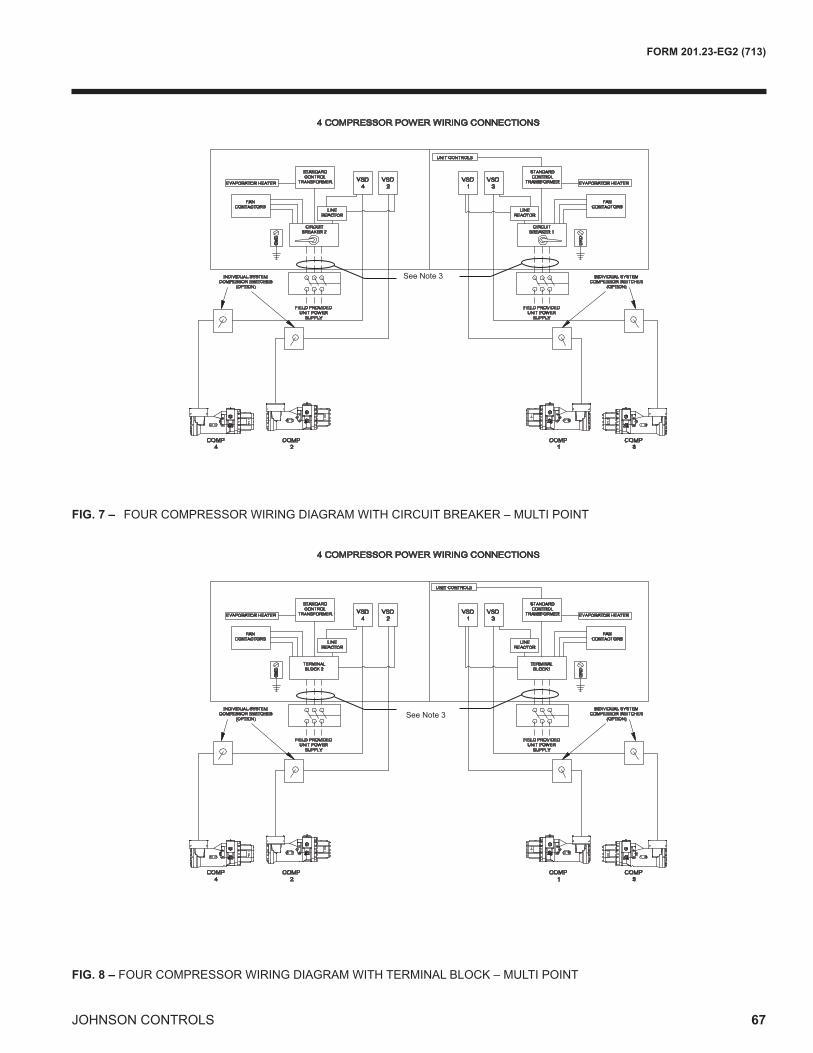
JOHNSON CONTROLS
FORM 201.23-EG2 (713)
67
FIG. 7 – FOURCOMPRESSORWIRINGDIAGRAMWITHCIRCUITBREAKER–MULTIPOINT
FIG. 8 – FOURCOMPRESSORWIRINGDIAGRAMWITHTERMINALBLOCK–MULTIPOINT

JOHNSON CONTROLS68
FORM 201.23-EG2 (713)Typical Control Wiring - Two Compressor
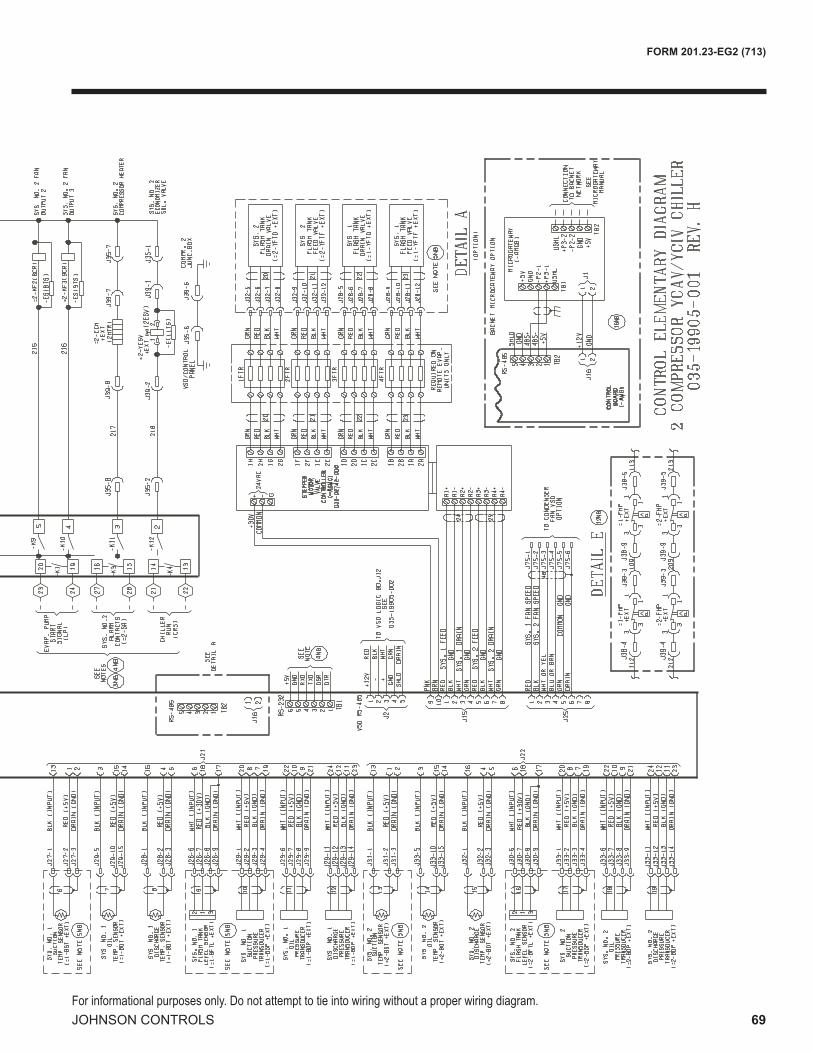
JOHNSON CONTROLS
FORM 201.23-EG2 (713)
69For informational purposes only. Do not attempt to tie into wiring without a proper wiring diagram.

JOHNSON CONTROLS70
FORM 201.23-EG2 (713)Typical Control Wiring - Three Compressor

JOHNSON CONTROLS
FORM 201.23-EG2 (713)
71For informational purposes only. Do not attempt to tie into wiring without a proper wiring diagram.

JOHNSON CONTROLS72
FORM 201.23-EG2 (713)Typical Control Wiring - Four Compressor

JOHNSON CONTROLS
FORM 201.23-EG2 (713)
73

JOHNSON CONTROLS74
FORM 201.23-EG2 (713)
UNIT LOCATION
TheYCIVchillersaredesignedforoutdoorinstallation.Whenselectingasitefor installation,beguidedbythefollowingrequirements:
1. Installationsitesmaybeeitheronarooforongroundlevel.(SeeFOUNDATION)
2. Selectaplacehavinganadequatesupplyoffreshairforthecondensers.RecommendedclearancesforallunitsareshownontheDIMENSIONSpages.
3. Avoid locations near windows or structures wherenormaloperatingsoundsmaybeobjectionable.
4. Thecondenserfansarepropeller-typeandarenotrecommendedforusewithductwork,filtersorotherimpedementstoairflowinthecondenserairstream.
5. Whenitisdesirabletosurroundtheunit(s),inadditiontowhateveroptionallouverpackageisselected,itisrecommendedthatthescreeningbeabletopasstherequiredchillerCFMwithoutexceeding0.1"externalstaticpressure.
6. Protectionagainstcorrosiveenvironmentsisavailablebyorderingtheunitswitheithercopperfinsorcuredepoxy-coatingonthecondensercoils.Epoxy-coatedcoilsshouldbeutilizedwithanyunitsbeinginstalledattheseashore,orwheresaltspraymayhittheunits,orwhereacidrainisprevalent(coppercondensercoilsarenotrecommendedwheretheymaybeexposedtoacidrain).
7. Oninstallationswherewinteroperationisintendedandsnowaccumulationsareexpected,additionalelevationmustbeprovidedtoinsurenormalcondenserairflow.
FOUNDATION
Theunitshouldbemountedonaflatandlevelfounda-tion, ground or roof, capable of supporting the entireoperatingweightoftheequipment.PleasecontactyournearestJohnsonControlsSalesOfficeforshippingandoperatingweights.
Roof Locations – Adequatestructuralstrengthtosafelysupporttheentireweightoftheunitandserviceperson-nelmustbeprovided.Caremustbetakennottodamagetheroofduringinstallation.Iftheroofis“bonded”,consultbuildingcontractororarchitectforspecialinstallationre-quirements.Roofinstallationsshouldincorporatetheuseofspring-type isolators tominimizethetransmissionofvibrationintobuildingstructure.Additionalsupportshouldbeprovidedtotheroofatthespring-isolatorlocations.
Ground Locations – Unitsmustbeinstalledonasub-stantialbasethatwillnotsettleandcausestrainontherefrigerantlines,resultinginpossibleleaks.Aone-piececoncreteslab,withfootersextendingbelowthefrostline,isrecommended.Theslabshouldnotbetiedtothemainbuildingfoundationasoperationalnoisewilltelegraph.
Mountingholes(5/8")areprovidedinthebaserailsforboltingtheunittoitsfoundation.SeeDIMENSIONSforlocationofthemountingholes.
Forgroundinstallations,precautionsshouldbetakentoprotecttheunitfromtamperingby,orinjuryto,unauthor-izedpersons.Fastenersonaccesspanelswillpreventcasual tampering; however, further safety precautions,suchasunitenclosureoptions,afenced-inenclosure,orlockingdevicesonthepanelsmaybeadvisable.Checklocalauthoritiesforsafetyregulations.
CHILLED LIQUID PIPING
Thechilledliquidpipingsystemshouldbelaidoutsothatthecirculatingpumpdischargesintothecooler.Theinletandoutletcooler-liquidconnectionsaregiveninDIMEN-SIONS.Handstopvalvesarerecommendedforuseinalllinestofacilitateservicing.Drainconnectionsshouldbeprovidedatalllowpointstopermitcompletedrainageofthecoolerandsystempiping.
Theevaporatormustbeprotectedbyastrainer,preferablyof40mesh,fittedascloseaspossibletotheliquidinletconnection,andprovidedwithameansoflocalisolation.
Theevaporatormustnotbeexposedtoflushingvelocitiesordebrisreleasedduringflushing.Itisrecommendedthatasuitablysizedbypassandvalvearrangementisinstalledtoallowflushingofthepipingsystem.Thebypasscanbeusedduringmaintenancetoisolatetheheatexchangerwithoutdisruptingflowtootherunits.Pressure-gaugeconnectionsarerecommendedforinstal-lationintheinletandoutletwaterlines.Gaugesarenotprovidedwiththeunitandaretobefurnishedbyothers.
Chilled liquid lines exposed to the weather should bewrappedwithasupplementalheatercableandinsulated,orglycolshouldbeaddedtothechilledliquidtoprotectagainstfreezingiflow-ambientperiodsareexpected.
Aflowswitchisavailableasanaccessoryonallunits.Aflowswitchmustbeinstalledintheleavingwaterpipingofthecoolerandmustnotbeusedtostartandstoptheunit.
Application Data

JOHNSON CONTROLS
FORM 201.23-EG2 (713)
75
Guide Specifications
PART 1 — GENERAL
1.01 SCOPE
A.TherequirementsoftheGeneralConditions,Supple-mentaryConditions,andDrawingsapplytoallworkherein.
B. Providemicrocomputer controlled, twin-screwcom-pressor, air-cooled, liquid chillers of the scheduledcapacitiesasshownandindicatedonthedrawings,includingbutnotlimitedto:1.Chillerpackage2.Chargeofrefrigerantandoil.3.Electricalpowerandcontrolconnections4.Chilledwaterconnections5.Factorystart-up
1.02 QUALITY ASSURANCE
A.ProductsshallbeDesigned,Tested,RatedandCerti-fiedIAW,andinstalledincompliancewithapplicablesectionsofthefollowingStandardsandCodes:1. AHRI550/590–WaterChillingPackagesUs-
ing theVaporCompressionCycle2. AHRI70–SoundRatingofLargeOutdoorRe-
frigeratingandAirConditioningEquipment3. ANSI/ASHRAEStandard15–SafetyCodefor
MechanicalRefrigeration4. ASHRAE34–NumberDesignationandSafety
ClassificationofRefrigerants5. ASHRAE90.1–EnergyStandardforBuildings
ExceptLow-RiseResidentialBuildings6. ANSI/NFPAStandard 70 –NationalElectrical
Code(N.E.C).7. ASMEBoilerandPressureVesselCode,Section
VIII,Division1.8. ASTMA48–GrayIronCastings9. OSHA–OccupationalSafetyandHealthAct10. ManufacturedinfacilityregisteredtoISO900111. ConformtoUnderwritersLaboratories(U.L.)for
constructionof chillers andprovideU.L./cU.L.listinglabel.
B.FactoryTest:Chillershallbepressure-tested,evacu-atedandfullychargedwithrefrigerantandoil,andshallbeoperationallyruntestedwithwaterflowingthroughthevesselatthefactory.
C.Chillermanufacturershallhaveafactorytrainedandsupportedserviceorganization.
D.Warranty:ManufacturershallWarrantallequipmentandmaterial of itsmanufacture against defects inworkmanship andmaterial for a periodof eighteen(18)months fromdate of initial start-up or date ofavailability.
1.03 DELIVERY AND HANDLING
A. UnitshallbedeliveredtojobsitefullyassembledandchargedwithrefrigerantandoilbytheManufacturer.
B. During shipment, provide protective covering overvulnerablecomponents.Fitnozzlesandopenendswithplasticenclosures.
C. UnitshallbestoredandhandledperManufacturer’sinstructions.
PART 2 — PRODUCTS
2.01 GENERAL
A.Manufacturers:ThedesignshownonthedrawingsisbasedonaJohnsonControlsdesign.Alternateequip-mentwillbeacceptable if theequipmentmeets thescheduledperformanceandcomplieswithJohnsonControls'specifications.Ifequipmentmanufacturedbyamanufacturerotherthanthatscheduledisutilized,thentheMechanicalContractorshallberesponsibleforcoordinatingwiththeGeneralContractorandallaffectedSubcontractors to insureproperprovisionsforinstallationofthefurnishedunit.Thiscoordinationshallinclude,butnotbelimitedto,thefollowing:
1. Structuralsupportsforunits.2. Pipingsizeandconnection/headerlocations.3. Electricalpowerrequirementsandwire/conduit
andovercurrentprotectionsizes.4. Chillerphysicalsizeonplantlayout.5. Sitenoiseconsiderations.
TheMechanicalContractor shall be responsible forallcosts incurredby theGeneralContractor,Subcontrac-tors,andConsultantstomodifythebuildingprovisionstoacceptthefurnishedunits.
B.Description:Installandcommission,asshownontheschedules and plans, factory assembled, charged,andoperationaltestedair-cooledscrewcompressorchiller(s)asspecifiedherein.Chillershallinclude,butisnotlimitedto:acompletesystemwithmultipleinde-pendentrefrigerantcircuits,semihermetictwinscrewcompressors, shell and tube type evaporator, air-cooledcondenser,HFC-134arefrigerant,lubricationsystem,interconnectingwiring,safetyandoperating

JOHNSON CONTROLS76
FORM 201.23-EG2 (713)Guide Specifications
controlsincludingcapacitycontroller,controlcenter,motorstartingcomponents,andspecial featuresasspecifiedhereinorrequiredforsafe,automaticopera-tion.
C. OperatingCharacteristics:1. Provide lowambientcontrolandhighambient
options as required to ensure unit is capableofoperationfrom0°Fto125°F(-18°Cto52°C)ambient.
2. Providecapacitycontrolsystemcapableofre-ducingunitcapacityto(10%for2compressorunits,7.5%for3compressorunits,and5%for4compressorunits)offullload.Compressorshallstartinunloadedcondition.Applicationoffactoryinstalledhotgasbypassshallbeacceptableasrequiredtomeetspecifiedminimumload.
D. Cabinet: Unit panels, structural elements, controlboxes and heavy gauge structural base shall beconstructedofgalvanizedsteel.Unitpanels,controlboxesandstructuralbasearefinishedwithabakedonpowderpaint.Allpaintedsurfacesshallbecoatedwithbakedonpowderpaintwhich,whensubject toASTMB117, 1,000 hour, 5% salt spray test, yieldsminimumASTM1654ratingof“6”.
E.Unitshallshipinonepieceandshallrequireinstallertoprovideonlyasingleevaporatorinletandoutletpipeconnection. Ifachillermodel thatships inmultiplepieces isprovided,bidshall includeall thematerialandfieldlaborcostsforfactoryauthorizedpersonneltoinstallatrimkittoconnectthepiecesaswellasallinterconnectingpipingandwiring.
2.02 COMPRESSORS AND MOTORS
A.Compressors: Shall be direct drive, semihermetic,rotarytwin-screwtype,including:muffler,temperatureactuated‘off-cycle’heater,rain-tightterminalbox,dis-chargeshut-offservicevalve,andprecisionmachinedcastironhousingmountedonelastomericisolators.Designworkingpressureofentirecompressor,suctiontodischarge,shallbe350psig (24barg)orhigher.CompressorshallbeU.L.recognized.
B.Motors:Refrigerant suction-gas cooled accessiblehermetic compressormotor, full suction gas flowthrough0.006”maximummeshscreen,withinherentinternalthermaloverloadprotectionandexternalcur-rentoverloadonallthreephases.
C.Lubrication:External oil separatorswith nomovingparts,450psigdesignworkingpressure,andULlistingareprovidedonthechiller.Refrigerantsystemdiffer-
entialpressureshallprovideoilflowthroughservicereplaceable,0.5micron,fullflow,cartridgetypeoilfilterinternaltocompressor.Filterbypass,lessrestrictivemedia,oroilpumpnotacceptable.
D. CapacityControl:Compressorsshallstartatminimumload. ProvideMicroprocessor control to commandcompressorcapacitytobalancecompressorcapacitywithcoolingload.Whenrequiredtomeetminimumload, hot gasbypass shall be factory installedandintegratedintostandardcontrolsystem.
2.03 REFRIGERANT CIRCUIT COMPONENTS
A.Each independent refrigerant circuit shall include:liquid lineshutoffvalvewithchargingport, lowsidepressurereliefdevice,removablecorefilter-drier,sightglasswithmoistureindicator,andelectronicexpansionvalve(EEV).
B. Chillermanufacturershallprovideindependentcircuitforeachcompressortoprovidemaximumredundancyduringchilleroperation.Ifequipmentdoesnothaveindependent circuits per compressor,manufacturershallprovideowneronesparecompressorofeachuniquesize.
C. Dischargelinesshallbeprovidedwithmanualcom-pressorshutoffservicevalves.Suction lineshallbecoveredwithclosedcellfoaminsulation.
2.04HEATEXCHANGERS
A.Evaporator:1. Directexpansiontypeorfloodedtypeshelland
tube evaporator with high efficiency coppertubes.Independentrefrigerantcircuitsshallbeprovidedpercompressor.
2. Constructed, tested, and stamped IAWappli-cablesectionsofASMEpressurevesselcodeforminimum235psig(16barg)refrigerantsidedesignworkingpressureand150psig(10barg)watersidedesignworkingpressure.
3. Shellcoveredwith3/4”(19mm),flexible,closed-cell insulation, thermal conductivity of 0.26k(BTU/HR-Ft2-°F/in.)maximum.Water nozzleswith grooves formechanical couplings, andinsulatedbyContractorafterpipeinstallation.
4. Provide vent and drain fittings, and thermo-staticallycontrolledheaterstoprotectto-20°F(-29°C)ambientinoff-cycle.
B.Air-cooledCondenser:1. Coils: Internally enhanced, seamless copper
tubes,mechanically expanded into aluminum

JOHNSON CONTROLS
FORM 201.23-EG2 (713)
77
alloyfinswithfullheightcollars.Subcoolingcoilan integral partof condenser.Designworkingpressureshallbe450psig(31barg).
2. LowSoundFans:Shallbedynamicallyandstati-callybalanced,directdrive,corrosionresistantglassfiberreinforcedcompositebladesmoldedintolownoise,fullairfoilcrosssection,provid-ingverticalairdischargefromextendedorifices.Guardsofheavygauge,PVC(polyvinylchloride)coatedorgalvanizedsteel.
3. FanMotors:Highefficiency,directdrive,3-phase,insulation class “F”, current protected,TotallyEnclosedAirOver(TEAO),withdoublesealed,permanentlylubricatedballbearings.
2.05 POWER AND ELECTRICAL REQUIREMENTS
A.Power/ControlPanel:1. NEMA3R (IP55), powder painted steel cabi-
netswith hinged, latched, and gasket sealedouterdoorsequippedwithwindstrutsforsaferservicing. Providemain power connection(s),compressorstartersandfanmotorcontactors,currentoverloads,andfactorywiring.
2. Panelshallincludecontroldisplayaccessdoor.
B.SinglePointPower(Asstandardfor2and3compres-sorchillers)1. Providesinglepointpowerconnectiontochiller,
shallbe3phaseofscheduledvoltage.
2. TerminalBlockconnectionsshallbeprovidedatthepointofincomingsinglepointconnection.
C.ControlTransformer:Powerpanelshallbesuppliedwithafactorymountedandwiredcontroltransformerthatwillsupplyallunitcontrolvoltagefromthemainunitpowersupply.Transformershallutilizescheduledlinevoltageontheprimarysideandprovide115V/1Øonsecondary.
D.ShortCircuitWithstandRatingofthechillerelectricalenclosureshallbe(380,400,&460V:65,000Amps).RatingshallbeIAWUL508.
E. MotorStarters:Motorsstartersshallbereducedinrushtype(Wye-DeltaorSolidState)forminimumelectricalinrush.Acrossthelinetypestarterswillnotbeaccept-able.
F. PowerFactor:1. Provideequipmentwithpowerfactorcorrection
capacitorsas required tomaintainadisplace-mentpowerfactorof95%atallloadconditions.
2. The installingcontractor is responsible forad-ditionalcosttofurnishandinstallpowerfactorcorrection capacitors if they are not factorymountedandwired.
G. Exposedcompressorandfanmotorpowerwiringshallberoutedthroughliquidtightconduit.
2.06 CONTROLS
A.General:1. Provide automatic control of chiller operation
includingcompressorstart/stopandload/unload,anti-recycletimers,condenserfans,evaporatorpump,evaporatorheater,unitalarmcontactsandrunsignalcontacts.
2. Chillershallautomaticallyresettonormalchilleroperationafterpowerfailure.
3. Unitoperatingsoftwareshallbestoredinnon-volatilememory.Fieldprogrammedsetpointsshallberetainedinlithiumbatterybackedregu-latedtimeclock(RTC)memoryforminimum5years.
4. Alarmcontactsshallbeprovidedtoremotealertforanyunitorsystemsafetyfault.
B.DisplayandKeypad:1. Provideminimum 80 character liquid crystal
display that isbothviewable indirect sunlightandhasLEDbacklightingfornighttimeviewing.Provideonekeypadanddisplaypanelperchiller.
2. Displayandkeypadshallbeaccessiblethroughdisplayaccessdoorwithoutopeningmaincon-trol/electricalcabinetdoors.
3. Displayshallprovideaminimumofunitsetpoints,status,electricaldata,temperaturedata,pres-sures,safety lockoutsanddiagnosticswithouttheuseofacodeddisplay.
4. Descriptions inEnglish (oravailable languageoptions), numeric data in English (orMetric)units.
5. SealedkeypadshallincludeunitOn/Offswitch.
C. ProgrammableSetpoints(withinManufacturerlimits):displaylanguage;leavingchilledliquidtemperature:setpoint,controlrange;localorremotecontrol;unitsofmeasure;compressorlead/lag;andmaximumchilledwatersetpointresettemperaturerange.
D. DisplayData:Chillerliquidreturnandleavingtempera-tures,ambient,leadcompressoridentification,clockandschedule, (variable)outof range, remote inputindication, chilled liquid reset setpoint, and history

JOHNSON CONTROLS78
FORM 201.23-EG2 (713)
data for last ten shutdown faults.Compressor suc-tion,discharge,andoilpressuresandtemperatures,suctionanddischargesuperheats,percentoffull-load,operatinghours,starts,andanti-recycletimerstatus.StatusMessagesformanualoverride,unitswitchoff,compressor run, run permissive, remote controlledshutdown,nocoolingload,daily/holidayshutdown,anti-recycletimer.
E. PredictiveControlPoints: Unit controls shall avoidsafetyshutdownwhenoperatingoutsidedesigncon-ditionsbyoptimizingthechillercontrolsandcoolingloadoutputtostayonlineandavoidsafetylimitsbe-ingreached.Thesystemshallmonitorthefollowingparametersandmaintainthemaximumcoolingoutputpossiblewithoutshutdownof theequipment:motorcurrent,suctionpressureanddischargepressure.
F. SystemSafeties:Shallcauseindividualcompressorsystemstoperformauto-resetshutdown;manualresetrequiredafter the third trip in90minutes. Includes:highdischargepressureortemperature,lowsuctionpressure,high/ lowmotorcurrent,highmotor tem-perature,highpressureswitch,high/lowdifferentialoilpressure,highoiltemperature,lowsuctionsuperheat,criticalsensormalfunction,loworhighcurrent,phaseloss/singlephasepower,overloadofmotorwindings,andlowvoltage.
G. Unit Safeties:Shall be automatic reset and causecompressorstoshutdownif:highorlowambient,lowleavingchilledliquidtemperature,undervoltage,andflowswitchoperation.Contractor shall provideflowswitch andwiring per chillermanufacturer require-ments.
H. Manufacturer shall provide any controls not listedabove,necessaryforautomaticchilleroperation.Me-chanicalContractorshallprovidefieldcontrolwiringnecessary to interfacesensors to thechillercontrolsystem.
2.07 ACCESSORIES and OPTIONS
Someaccessoriesandoptionssupersedestandardprod-uctfeatures.YourJohnsonControlsrepresentativewillbepleasedtoprovideassistance.
A.SoundReduction1. Providethefollowingoptionsasrequiredtomeet
scheduledsoundperformancedataatall loadpoints.a.Normalspeedfansandunlinedcompressor
enclosure.(Factory Mounted)
b.Two-speedfansandacousticalllylinedenclo-sure.(Factory Mounted)
c. Soundpoweroctavebanddata,dBperAHRIstandard70andIAWISO3744at35°Cambi-entand7°Cleavingchilledwater.
2. Provideoptionalcontrolinputtolimitsoundout-putofthechillerbasedontimeofday.Shallbeprogrammableatthechillerpanelorcontrolledremotelyviasignal(4-20mAor0-10VDC)fromBASsystem.Chillerswithoutthisfeatureshallbeprovidedwiththenecessarysoundattenua-tiontomeetthescheduledsoundperformancedataatallloadpoints.
B.PowerSupply/Connections:1. Circuitbreaker isoptionalatpointof incoming
singlepointconnection toprovidedisconnect-ingmeansANDbesizedtoprovidethemotorbranch circuit protection, short circuit protec-tion andground fault protection for themotorbranch-circuit conductors, themotor controlapparatusandthemotors.Circuitbreakershallbeequippedwithlockableoperatinghandlethatshallextendthroughpowerpaneldoorsothatpowermaybedisconnectedwithoutopeninganypaneldoors.
C.CondenserCoilEnvironmentalProtection:1. PRE-COATED FIN CONDENSER COILS – Theair-cooledcondensercoilsareconstructed
ofepoxy-coatedaluminumfins.2. COPPER FIN – Provide condenser coilswith
copperfinsinlieuofaluminumfins.3. POST-COATEDEPOXYDIPPEDCONDENSER
COILS –Theunitisbuiltwithdipped-curedcon-densercoils.
D.ProtectiveChillerPanels(Factory Mounted):1.LouveredPanels (condenser coils only):Painted
steeltomatchunitpanels,overexternalcondensercoilfaces.
2.WirePanels(fullunit):Heavygauge,weldedwiremesh, coated to resist corrosion, to protect con-denser coils from incidental damageand restrictunauthorizedaccesstointernalcomponents.3. LouveredPanels (full unit): Painted steel to
match unit panels, to protect condenser coilsfromincidentaldamage,visuallyscreeninternalcomponents,andpreventunauthorizedaccesstointernalcomponents.
4. Louvered/WirePanels:Louveredsteelpanelsonexternalcondensercoilfaces,paintedtomatch
Guide Specifications

JOHNSON CONTROLS
FORM 201.23-EG2 (713)
79
unit panels.Heavygauge,weldedwire-mesh,coatedtoresistcorrosion,aroundbaseofma-chinetorestrictunauthorizedaccess.
E.Evaporatoroptions:1. Provide1-1/2”(38mm)coolerinsulationinlieu
ofstandard3/4”(19mm).2. ProvideRaisedFaceFlangesforcoolernozzles:
a.150psig(10.3barg),weldedflanges(fieldkit,matchingpipeflangebycontractor).
b.150psig(10.3barg)companionflanges.(notavailablewith460Vunits)
c. 150 psig (10.3 barg),ANSI/AWWAC-606couplings(fieldkit,matchingpipeflangebycontractor).
F. FlowSwitch (Field Mounted): Vapor proof SPDT,NEMA3Rswitch[___150psig(10.3barg)or___300psig(20.7barg)],-20°Fto250°F(-28.9°Cto121.1°C).
G.BuildingAutomationSystemInterface:1. Chillertoaccept4to20mAor0to10VDCinput
to reset the leavingchilled liquid temperature.(Factory Mounted)
H.Multi-UnitSequenceControl(Field Mounted):Sepa-rateSequencing control center provided to permitcontrolofuptoeightchillersinparallelbasedonmixedliquidtemperature.
I. VibrationIsolation(Field Mounted):1. ElastomericIsolators.2. 1InchDeflectionSpringIsolators:Leveladjust-
able,springandcagetypeisolatorsformountingundertheunitbaserails.
3. 2"DeflectionSeismic Isolators: Level adjust-able,restrainedmountsinruggedweldedsteelhousingwithverticalandhorizontallimitstops.Housingsshallbedesignedtowithstandamini-mum1.0gacceleratedforceinalldirectionsto2”(50.8mm).
J.ServiceShut-OffValve:Providesuctionserviceshut-offvalveforeachcompressor.(Factory Mounted)
PART3—EXECUTION
3.01 INSTALLATION
A.General: Rig and Install in full accordance withManufacturer’srequirements,Projectdrawings,andContractdocuments.
B.Location:Locatechillerasindicatedondrawings,in-cludingcleaningandservicemaintenanceclearanceperManufacturerinstructions.Adjustandlevelchilleronsupportstructure.
C.Components:InstallingContractorshallprovideandinstallallauxiliarydevicesandaccessories for fullyoperationalchiller.
D.Electrical:Coordinateelectricalrequirementsandcon-nectionsforallpowerfeedswithElectricalContractor(Division16).
E.Controls:Coordinate all control requirements andconnectionswithControlsContractor.
F. Finish:InstallingContractorshallpaintdamagedandabraded factoryfinishwith touch-uppaintmatchingfactoryfinish.
Form201.23-EG2(713)NewRelease