model w1867/w1868/w1869 cyclone dust collectors · additional safety for dust collectors ..... 9...
TRANSCRIPT

OWNER'S MANUAL(FOR MODELS MANUFACTURED SINCE 06/20)
MODEL W1867/W1868/W1869 CYCLONE
DUST COLLECTORS
Phone: (360) 734-3482 • Online Technical Support: [email protected]
COPYRIGHT © JANUARY, 2019 BY WOODSTOCK INTERNATIONAL, INC., REVISED JULY, 2020 (MN)WARNING: NO PORTION OF THIS MANUAL MAY BE REPRODUCED IN ANY SHAPE OR FORM WITHOUT
THE WRITTEN APPROVAL OF WOODSTOCK INTERNATIONAL, INC.#20207KBES Printed in Taiwan
W1867 W1868 W1869
V2.07.20
This manual provides critical safety instructions on the proper setup, operation, maintenance, and service of this machine/tool. Save this document, refer to it often, and use it to instruct other operators.
Failure to read, understand and follow the instructions in this manual may result in fire or serious personal injury—including amputation, electrocution, or death.
The owner of this machine/tool is solely responsible for its safe use. This responsibility includes but is not limited to proper installation in a safe environment, personnel training and usage authorization, proper inspection and maintenance, manual availability and compre-hension, application of safety devices, cutting/sanding/grinding tool integrity, and the usage of personal protective equipment.
The manufacturer will not be held liable for injury or property damage from negligence, improper training, machine modifications or misuse.
Some dust created by power sanding, sawing, grinding, drilling, and other construction activities contains chemicals known to the State of California to cause cancer, birth defects or other reproductive harm. Some examples of these chemicals are:
• Lead from lead-based paints.• Crystalline silica from bricks, cement and other masonry products.• Arsenic and chromium from chemically-treated lumber.
Your risk from these exposures varies, depending on how often you do this type of work. To reduce your exposure to these chemicals: Work in a well ventilated area, and work with approved safety equip-ment, such as those dust masks that are specially designed to filter out microscopic particles.
SETUP
ELECTRICA
LM
AIN
TENA
NCE
SERVICEPA
RTSO
PERATIO
NS
SAFET
YIN
TRODU
CTION
USE THE QUICK GUIDE PAGE LABELS TO SEARCH OUT INFORMATION FAST!
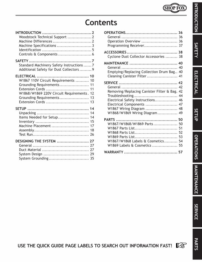
INTRODUCTION......................................2Woodstock Technical Support .................. 2Machine Differences ............................. 2Machine Specifications .......................... 3Identification ..................................... 5Controls & Components ......................... 6
SAFETY................................................7Standard Machinery Safety Instructions ...... 7Additional Safety for Dust Collectors ......... 9
ELECTRICAL........................................ 10W1867 110V Circuit Requirements .......... 10Grounding Requirements ...................... 11Extension Cords ................................ 11W1868/W1869 220V Circuit Requirements . 12Grounding Requirements ...................... 13Extension Cords ................................ 13
SETUP............................................... 14Unpacking ....................................... 14Items Needed for Setup ....................... 14Inventory ........................................ 15Machine Placement ............................ 17Assembly ......................................... 18Test Run .......................................... 26
DESIGNING.THE.SYSTEM......................... 27General .......................................... 27Duct Material ................................... 27System Design .................................. 29System Grounding .............................. 35
OPERATIONS....................................... 36General .......................................... 36Operation Overview ........................... 36Programming Receiver ......................... 37
ACCESSORIES....................................... 38Cyclone Dust Collector Accessories ......... 38
MAINTENANCE..................................... 40General .......................................... 40Emptying/Replacing Collection Drum Bag .. 40Cleaning Canister Filter ....................... 41
SERVICE............................................. 42General .......................................... 42Removing/Replacing Canister Filter & Bag . 42Troubleshooting ................................. 44Electrical Safety Instructions ................. 46Electrical Components ........................ 47W1867 Wiring Diagram ........................ 48W1868/W1869 Wiring Diagram ............... 49
PARTS............................................... 50W1867/W1868/W1869 Parts .................. 50W1867 Parts List ................................ 51W1868 Parts List ................................ 52W1869 Parts List ................................ 53W1867/W1868 Labels & Cosmetics .......... 54W1869 Labels & Cosmetics ................... 55
WARRANTY......................................... 57
Contents

-2-
Model W1867/W1868/W1869 (For Machines Mfd. Since 06/20)IN
TRO
DUCT
ION
INTRODUCTION
Model.W1867:• 1.5 HP 110V Single-Phase Motor• 6" Dust Port Inlet with 2 x 4" Adapter• 868 CFM @ 1.8" SP• 1-Micron Canister Filter • 20-Gallon Collection Drum
Model.W1868:• 2 HP 220V Single-Phase Motor• 7" Dust Port Inlet with 3 x 4" Adapter• 1023 CFM @ 1.2" SP• 1-Micron Canister Filter• 20-Gallon Collection Drum
Model.W1869:• 3 HP 220V Single-Phase Motor• 8" Dust Port with 3 x 4" Adapter• 1941 CFM @ 2.9" SP• 1-Micron Canister Filter• 35-Gallon Collection Drum
Machine.Differences
Woodstock.Technical.SupportThis machine has been specially designed to provide many years of trouble-free service. Close attention to detail, ruggedly built parts and a rigid quality control program assure safe and reliable operation.
Woodstock International, Inc. is committed to customer satisfaction. Our intent with this manual is to include the basic information for safety, setup, operation, maintenance, and service of this product.
We stand behind our machines! In the event that questions arise about your machine, please contact Woodstock International Technical Support at (360) 734-3482 Ext. 2 or send e-mail to: [email protected]. Our knowledgeable staff will help you troubleshoot problems and process warranty claims.
If you need the latest edition of this manual, you can download it from http://www.woodstockint.com/manuals. If you have comments about this manual, please contact us at:
Woodstock.International,.Inc.Attn:.Technical.Documentation.Manager
P.O..Box.2309Bellingham,.WA.98227
Email:[email protected]
-3-
Model W1867/W1868/W1869 (For Machines Mfd. Since 06/20)IN
TRODU
CTION
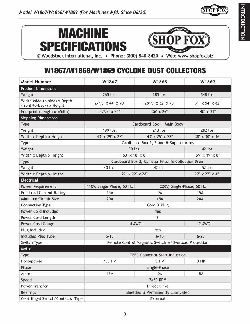
Machine.Specifications
Model W1867 Machine Specifications, Page 1 of 3
MODEL W18671.5 HP PORTABLE CYCLONE DUST COLLECTOR
Product Dimensions
Weight.......................................................................................................... 265 lbs.Width (side‐to‐side) x Depth (front‐to‐back) x Height................................... 27‐1/2 x 44 x 70 in.Footprint (Length x Width)......................................................................... 32‐1/2 x 24 in.
Shipping Dimensions
Carton #1Type............................................................................................. Cardboard BoxContent............................................................................................... Main BodyWeight................................................................................................... 199 lbs.Length x Width x Height..................................................................... 43 x 29 x 23 in.Must Ship Upright........................................................................................... Yes
Carton #2Type............................................................................................. Cardboard BoxContent................................................................................ Stand & Support ArmsWeight.................................................................................................... 39 lbs.Length x Width x Height...................................................................... 50 x 18 x 8 in.Must Ship Upright............................................................................................ No
Carton #3Type............................................................................................. Cardboard BoxContent.................................................................. Canister Filter & Collection DrumWeight.................................................................................................... 40 lbs.Length x Width x Height..................................................................... 22 x 22 x 28 in.Must Ship Upright............................................................................................ No
Electrical
Power Requirement.................................................................... 110V, Single‐Phase, 60 HzFull‐Load Current Rating......................................................................................... 15AMinimum Circuit Size............................................................................................. 20AConnection Type......................................................................................... Cord & PlugPower Cord Included.............................................................................................. YesPower Cord Length............................................................................................... 6 ft.Power Cord Gauge............................................................................................ 14 AWGPlug Included....................................................................................................... YesIncluded Plug Type............................................................................................... 5‐15Switch Type........................................ Remote‐Control Magnetic Switch w/Overload Protection
W1867/W1868/W1869 CYCLONE DUST COLLECTORSModel.Number W1867 W1868 W1869Product Dimensions
Weight 265 lbs. 285 lbs. 348 lbs.
Width (side-to-side) x Depth (front-to-back) x Height 271⁄2" x 44" x 70" 281⁄2" x 52" x 70" 31" x 54" x 82"
Footprint (Length x Width) 321⁄2" x 24" 36" x 26" 40" x 31"
Shipping Dimensions
Type Cardboard Box 1, Main Body
Weight 199 lbs. 213 lbs. 282 lbs.
Width x Depth x Height 43" x 29" x 23" 43" x 29" x 23" 38" x 30" x 46"
Type Cardboard Box 2, Stand & Support Arms
Weight 39 lbs. 42 lbs.
Width x Depth x Height 50" x 18" x 8" 59" x 19" x 8"
Type Cardboard Box 3, Canister Filter & Collection Drum
Weight 40 lbs. 42 lbs. 52 lbs.
Width x Depth x Height 22" x 22" x 28" 27" x 27" x 45"
Electrical
Power Requirement 110V, Single-Phase, 60 Hz 220V, Single-Phase, 60 Hz
Full-Load Current Rating 15A 9A 15A
Minimum Circuit Size 20A 15A 20A
Connection Type Cord & Plug
Power Cord Included Yes
Power Cord Length 6'
Power Cord Gauge 14 AWG 12 AWG
Plug Included Yes
Included Plug Type 5-15 6-15 6-20
Switch Type Remote Control Magnetic Switch w/Overload Protection
Motor
Type TEFC Capacitor-Start Induction
Horsepower 1.5 HP 2 HP 3 HP
Phase Single-Phase
Amps 15A 9A 15A
Speed 3450 RPM
Power Transfer Direct Drive
Bearings Shielded & Permanently Lubricated
Centrifugal Switch/Contacts Type External
-4-
Model W1867/W1868/W1869 (For Machines Mfd. Since 06/20)IN
TRO
DUCT
ION
Model.Number W1867 W1868 W1869
OperationDust Collector Type Two-Stage (Cyclone)
Approved Dust Types Wood
Filter Type Pleated Cartridge, Spun-Bond Polyester
Air Flow Performance 868 CFM @ 1.8" SP 1023 CFM @ 1.2" SP 1941 CFM @ 2.9" SP
Max. Static Pressure (at 0 CFM) 9.7" 10.9" 11.0"
Main Inlet Size 6" 7" 8"
Inlet Adapter Included Yes
Number of Adapter Inlets 2 3
Adapter Inlet Size 4" 4"
Machine Collection Capacity 2 Machines 3 Machines
Max. Material Collection Capacity 20 Gallons 35 Gallons
Bag.InformationNumber of Filter Bags 1
Number of Collection Drum Bags 1
Filter Bag Diameter 20"
Filter Bag Length 23"
Collection Drum Bag Diameter 30" 39"
Collection Drum Bag Length 41" 56"
Canister.Filter.InformationNumber of Canister Filters 1
Filtration Rating 1 Micron
Canister Filter Diameter 141⁄2"
Canister Filter Length 24" 393⁄8"
Filter Surface Area 28.1 sq. ft. 45.2 sq. ft.
Impeller.InformationImpeller Type Radial Fin
Impeller Size 123⁄4" 13" 15"
Impeller Blade Thickness 1⁄4" 1⁄8"
ConstructionDust Collection Bags Clear Plastic
Base Steel
Frame Steel
Impeller Cast Aluminum Steel
Impeller Housing Steel
Body Steel
Collection Drum Steel
Paint Type/Finish Powder Coated
Manufacturer.SpecificationsCountry of Origin Taiwan
Warranty 2 Years
Approx. Assembly & Setup Time 1 Hour
Serial Number Location ID Label on Impeller Housing
Sound Rating 78 dB 79 dB
ISO 9001 Factory Yes
-5-
Model W1867/W1868/W1869 (For Machines Mfd. Since 06/20)IN
TRODU
CTION
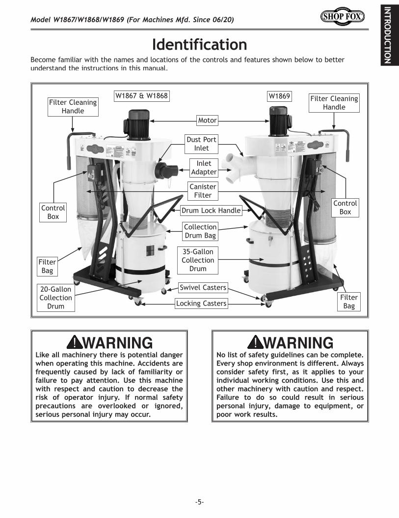
IdentificationBecome familiar with the names and locations of the controls and features shown below to better understand the instructions in this manual.
W1869W1867 & W1868
35-Gallon Collection
Drum
20-Gallon Collection
Drum
Inlet Adapter
Control BoxControl
Box
Filter Cleaning Handle
Filter Cleaning Handle
Motor
Dust Port Inlet
Canister Filter
Drum Lock Handle
Collection Drum Bag
Filter Bag
Filter Bag
Swivel Casters
Locking Casters
Like.all.machinery.there.is.potential.danger.when.operating.this.machine..Accidents.are.frequently. caused. by. lack. of. familiarity. or.failure. to. pay. attention.. Use. this. machine.with. respect. and. caution. to. decrease. the.risk. of. operator. injury.. If. normal. safety.precautions. are. overlooked. or. ignored,.serious.personal.injury.may.occur.
No.list.of.safety.guidelines.can.be.complete..Every.shop.environment.is.different..Always.consider. safety. first,. as. it. applies. to. your.individual.working.conditions..Use. this.and.other.machinery.with.caution.and.respect..Failure. to. do. so. could. result. in. serious.personal. injury,. damage. to. equipment,. or.poor.work.results.
-6-
Model W1867/W1868/W1869 (For Machines Mfd. Since 06/20)IN
TRO
DUCT
ION
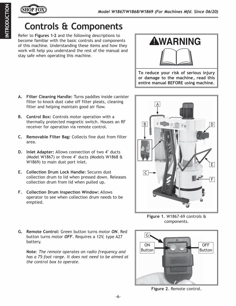
Controls.&.ComponentsRefer to Figures.1–2 and the following descriptions to become familiar with the basic controls and components of this machine. Understanding these items and how they work will help you understand the rest of the manual and stay safe when operating this machine.
Figure.1. W1867-69 controls & components.
A.. Filter.Cleaning.Handle: Turns paddles inside canister filter to knock dust cake off filter pleats, cleaning filter and helping maintain good air flow.
B.. Control.Box: Controls motor operation with a thermally protected magnetic switch. Houses an RF receiver for operation via remote control.
C.. Removable.Filter.Bag: Collects fine dust from filter area.
D.. Inlet.Adapter: Allows connection of two 4" ducts
(Model W1867) or three 4" ducts (Models W1868 & W1869) to main dust port inlet.
E.. Collection.Drum.Lock.Handle: Secures dust collection drum to lid when pressed down. Releases collection drum from lid when pulled up.
F.. Collection.Drum.Inspection.Window: Allows
operator to see when collection drum needs to be emptied.
To. reduce. your. risk. of. serious. injury.or. damage. to. the. machine,. read. this.entire.manual.BEFORE.using.machine.
B
A
C
D
E
F
Figure.2. Remote control.
G
OFF Button
ON Button
G.. Remote.Control: Green button turns motor ON. Red button turns motor OFF. Requires a 12V, type A27 battery.
Note: The remote operates on radio frequency and has a 75-foot range. It does not need to be aimed at the control box to operate.
Remote Control
-7-
Model W1867/W1868/W1869 (For Machines Mfd. Since 06/20)SA
FETY
Indicates.a.potentially.hazardous.situation.which,.if.not.avoided,.MAY.result.in.minor.or.moderate.injury.
Indicates.an.imminently.hazardous.situation.which,.if.not.avoided,.WILL.result.in.death.or.serious.injury.
Indicates.a.potentially.hazardous.situation.which,.if.not.avoided,.COULD.result.in.death.or.serious.injury.
This.symbol.is.used.to.alert.the.user.to.useful.information.about.proper.operation.of.the.equipment.or.a.situation.that.may.cause.damage.to.the.machinery.
NOTICE
SAFETY
OWNER’S.MANUAL..Read and understand this owner’s manual BEFORE using machine.
TRAINED.OPERATORS.ONLY..Untrained operators have a higher risk of being hurt or killed. Only allow trained/supervised people to use this machine. When machine is not being used, disconnect power, remove switch keys, or lock-out machine to prevent unauthorized use—especially around children. Make workshop kid proof!
DANGEROUS.ENVIRONMENTS..Do not use machinery in areas that are wet, cluttered, or have poor lighting. Operating machinery in these areas greatly increases the risk of accidents and injury.
MENTAL.ALERTNESS.REQUIRED..Full mental alertness is required for safe operation of machinery. Never operate under the influence of drugs or alcohol, when tired, or when distracted.
ELECTRICAL.EQUIPMENT.INJURY.RISKS..You can be shocked, burned, or killed by touching live electrical components or improperly grounded machinery. To reduce this risk, only allow an electrician or qualified service personnel to do electrical installation or repair work, and always disconnect power before accessing or exposing electrical equipment.
DISCONNECT.POWER.FIRST..Always disconnect machine from power supply BEFORE making adjustments, changing tooling, or servicing machine. This eliminates the risk of injury from unintended startup or contact with live electrical components.
EYE.PROTECTION..Always wear ANSI-approved safety glasses or a face shield when operating or observing machinery to reduce the risk of eye injury or blindness from flying particles. Everyday eyeglasses are not approved safety glasses.
Standard.Machinery.Safety.Instructions
For.Your.Own.Safety,Read.Manual.Before.Operating.Machine
The. purpose. of. safety. symbols. is. to. attract. your. attention. to. possible. hazardous. conditions.. This.manual.uses.a.series.of.symbols.and.signal.words.intended.to.convey.the.level.of.importance.of.the.safety.messages..The.progression.of.symbols.is.described.below..Remember.that.safety.messages.by.themselves.do.not.eliminate.danger.and.are.not.a.substitute. for.proper.accident.prevention.mea-sures—this.responsibility.is.ultimately.up.to.the.operator!
SAFETY
Standard.Machinery.Safety.Instructions
-8-
Model W1867/W1868/W1869 (For Machines Mfd. Since 06/20)SA
FET
Y
WEARING.PROPER.APPAREL..Do not wear clothing, apparel, or jewelry that can become entangled in moving parts. Always tie back or cover long hair. Wear non-slip footwear to avoid accidental slips, which could cause loss of workpiece control.
HAZARDOUS.DUST..Dust created while using machinery may cause cancer, birth defects, or long-term respiratory damage. Be aware of dust hazards associated with each workpiece material, and always wear a NIOSH-approved respirator to reduce your risk.
HEARING.PROTECTION..Always wear hearing protection when operating or observing loud machinery. Extended exposure to this noise without hearing protection can cause permanent hearing loss.
REMOVE.ADJUSTING.TOOLS..Tools left on machinery can become dangerous projectiles upon startup. Never leave chuck keys, wrenches, or any other tools on machine. Always verify removal before starting!
INTENDED.USAGE..Only use machine for its intended purpose—never make modifications without prior approval from Woodstock International. Modifying machine or using it differently than intended will void the warranty and may result in malfunction or mechanical failure that leads to serious personal injury or death!
AWKWARD.POSITIONS..Keep proper footing and balance at all times when operating machine. Do not overreach! Avoid awkward hand positions that make workpiece control difficult or increase the risk of accidental injury.
CHILDREN.&.BYSTANDERS..Keep children and bystanders at a safe distance from the work area. Stop using machine if they become a distraction.
GUARDS.&.COVERS..Guards and covers reduce accidental contact with moving parts or flying debris—make sure they are properly installed, undamaged, and working correctly.
FORCING.MACHINERY..Do not force machine. It will do the job safer and better at the rate for which it was designed.
NEVER.STAND.ON.MACHINE..Serious injury may occur if machine is tipped or if the cutting tool is unintentionally contacted.
STABLE.MACHINE..Unexpected movement during operation greatly increases risk of injury or loss of control. Before starting, verify machine is stable and mobile base (if used) is locked.
USE.RECOMMENDED.ACCESSORIES..Consult this owner’s manual or the manufacturer for recommended accessories. Using improper accessories will increase risk of serious injury.
UNATTENDED.OPERATION..To reduce the risk of accidental injury, turn machine OFF and ensure all moving parts completely stop before walking away. Never leave machine running while unattended.
MAINTAIN.WITH.CARE..Follow all maintenance instructions and lubrication schedules to keep machine in good working condition. A machine that is improperly maintained could malfunction, leading to serious personal injury or death.
CHECK.DAMAGED.PARTS..Regularly inspect machine for any condition that may affect safe operation. Immediately repair or replace damaged or mis-adjusted parts before operating machine.
MAINTAIN.POWER.CORDS..When disconnecting cord-connected machines from power, grab and pull the plug—NOT the cord. Pulling the cord may damage the wires inside, resulting in a short. Do not handle cord/plug with wet hands. Avoid cord damage by keeping it away from heated surfaces, high traffic areas, harsh chemicals, and wet/damp locations.
EXPERIENCING.DIFFICULTIES..If at any time you experience difficulties performing the intended operation, stop using the machine! Contact Technical Support at (360) 734-3482.
-9-
Model W1867/W1868/W1869 (For Machines Mfd. Since 06/20)SA
FETY
Additional.Safety.for.Dust.CollectorsLong-term.respiratory.damage.can.occur.from.using.dust.collectors.without.proper.use.of.a.respirator..Fire.or.explosions.can.result.in.smoke.inhalation,.serious.burns,.or.death—if.machine.is.used.to.collect.incorrect.materials,.is.operated.near.potential.explosion.sources,.or.ducting.is.improperly.grounded..Entanglement,.amputation,.or.death.can.occur.if.hair,.clothing,.or.fingers.are.pulled.into.the.inlet..To.reduce.the.risk.of.these.hazards,.operator.and.bystanders.MUST.completely.heed.the.hazards.and.warnings.below.
POWER.DISCONNECT. Turn machine OFF, disconnect from power supply, and allow impeller to completely stop before leaving machine unattended, or doing any maintenance or service.
REGULAR.CLEANING. To reduce risk of starting a fire, regularly check/empty collection bags or drum to avoid buildup of fine dust, which can increase risk of fire. Regularly clean surrounding area where machine is operated—excessive dust buildup on overhead lights, heaters, electrical panels, or other heat sources will increase risk of fire.
SUSPENDED.DUST.PARTICLES. To reduce risk of death or injury caused by explosions or fires, DO NOT operate in areas where these risks are high, including spaces near pilot lights, open flames, or other ignition sources.
AVOIDING.SPARKS. To reduce risk of fire, avoid collecting any metal objects or stones. These can possibly produce sparks when they strike impeller, which can smolder in wood dust for a long time before a fire is detected. If you accidentally cut into wood containing metal, immediately turn OFF dust collector, disconnect from power, and wait for impeller to stop. Then empty bag or drum into approved airtight metal container.
FIRE.SUPPRESSION.. Only operate dust collector in locations that contain fire suppression system or have fire extinguisher nearby.
STATIC.ELECTRICITY. To reduce risk of fire or explosions caused by sparks from static electricity, ground all ducting using grounding wire.
DUST.ALLERGIES. Dust from certain woods will cause an allergic reaction. Make sure you know what type of wood dust you will be exposed to in case of an allergic reaction.
INTENDED.USE. Collecting the wrong materials can result in serious inhalation hazards, fire, explosions, or machine damage. This machine is ONLY designed to collect wood dust and chips from woodworking machines. DO NOT use it to collect silica, polyurethane, toxic fumes, metal dust or shavings, lead paint, drywall, asbestos, biohazards, explosive dusts, flammable or combustible liquids or fumes, nor burning or smoking material.
WEAR.A.RESPIRATOR. Fine dust that is too small to be caught in filter will be blown into ambient air. Always wear a NIOSH-approved respirator during operation and for a short time after to reduce your risk of permanent respiratory damage. Never collect dust from any hazardous material.
IMPELLER.HAZARDS. To reduce risk of entanglement or contact with impeller, DO NOT place hands, hair, clothing, or tools in or near open dust collection inlet during operation, and keep small animals and children away. The powerful suction could easily pull them into impeller.
HAZARDOUS.DUST. Dust exposure created while using machinery may cause cancer, birth defects, or long-term respiratory damage. Be aware of dust hazards associated with each workpiece material, and always wear a NIOSH-approved respirator.
EMPTYING.DUST. When emptying bag or drum, wear respirator and safety glasses. Empty dust away from ignition sources and into approved container.
OPERATING.LOCATION. To reduce respiratory exposure to fine dust, locate permanently installed dust collectors away from working area or in another room. DO NOT place dust collector where it can be exposed to rain or moisture, which creates a shock hazard and will reduce life of machine.
-10-
Model W1867/W1868/W1869 (For Machines Mfd. Since 06/20)EL
ECTR
ICA
L
ELECTRICALW1867.110V.Circuit.
RequirementsThis machine must be connected to the correct size and type of power supply circuit, or fire or electrical damage may occur. Read through this section to determine if an adequate power supply circuit is available. If a correct circuit is not available, a qualified electrician MUST install one before you can connect the machine to power.
A power supply circuit includes all electrical equipment between the breaker box or fuse panel in the building and the machine. The power supply circuit used for this machine must be sized to safely handle the full-load current drawn from the machine for an extended period of time. (If this machine is connected to a circuit protected by fuses, use a time delay fuse marked D.)
Circuit.RequirementsThis machine is prewired to operate on a power supply circuit that has a verified ground and meets the following requirements:
Circuit.Type .................... 110V,.60.Hz,.Single-PhaseCircuit.Size ............................................ 20.AmpsPlug/Receptacle ................................... NEMA.5-15
Full-Load.Current.RatingThe full-load current rating is the amperage a machine draws at 100% of the rated output power. On machines with multiple motors, this is the amperage drawn by the largest motor or sum of all motors and electrical devices that might operate at one time during normal operations.
Full-Load.Current.Rating.(W1867)................ 15.Amps
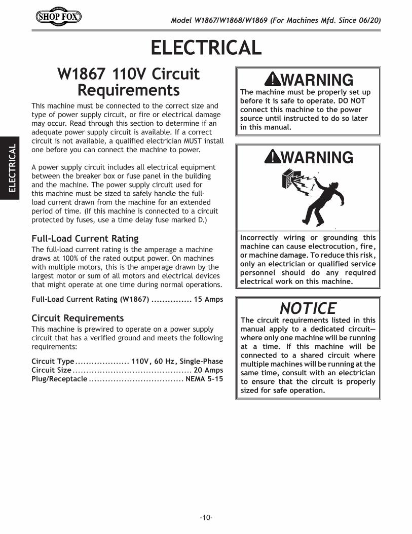
The machine must be properly set up before it is safe to operate. DO NOT connect this machine to the power source until instructed to do so later in this manual.
Incorrectly. wiring. or. grounding. this.machine.can.cause.electrocution,.fire,.or.machine.damage..To.reduce.this.risk,.only.an.electrician.or.qualified.service.personnel. should. do. any. required.electrical.work.on.this.machine.
NOTICE The.circuit. requirements. listed. in. this.manual. apply. to. a. dedicated. circuit—where.only.one.machine.will.be.running.at. a. time.. If. this. machine. will. be.connected. to. a. shared. circuit. where.multiple.machines.will.be.running.at.the.same.time,.consult.with.an.electrician.to. ensure. that. the. circuit. is. properly.sized.for.safe.operation.
Electrical
-11-
Model W1867/W1868/W1869 (For Machines Mfd. Since 06/20)ELECTRIC
AL
Grounding.RequirementsThis machine MUST be grounded. In the event of certain types of malfunctions or breakdowns, grounding provides a path of least resistance for electric current to travel—in order to reduce the risk of electric shock.
Improper connection of the equipment-grounding wire will increase the risk of electric shock. The wire with green insulation (with/without yellow stripes) is the equipment-grounding wire. If repair or replacement of the power cord or plug is necessary, do not connect the equipment-grounding wire to a live (current carrying) terminal. Check with a qualified electrician or service personnel if you do not understand these grounding requirements, or if you are in doubt about whether the tool is properly grounded. If you ever notice that a cord or plug is damaged or worn, disconnect it from power, and immediately replace it with a new one.
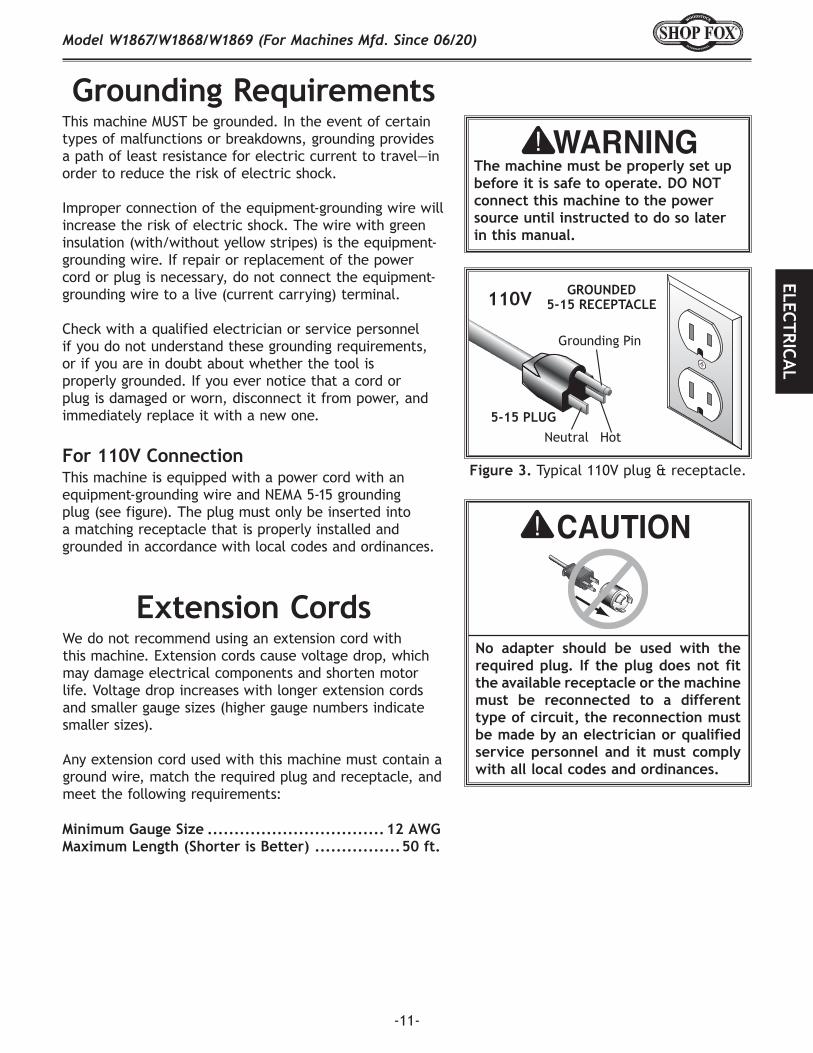
This machine is equipped with a power cord with an equipment-grounding wire and NEMA 5-15 grounding plug (see figure). The plug must only be inserted into a matching receptacle that is properly installed and grounded in accordance with local codes and ordinances.
For.110V.Connection
The machine must be properly set up before it is safe to operate. DO NOT connect this machine to the power source until instructed to do so later in this manual.
Extension.CordsWe do not recommend using an extension cord with this machine. Extension cords cause voltage drop, which may damage electrical components and shorten motor life. Voltage drop increases with longer extension cords and smaller gauge sizes (higher gauge numbers indicate smaller sizes).
Any extension cord used with this machine must contain a ground wire, match the required plug and receptacle, and meet the following requirements:
Minimum.Gauge.Size.................................. 12.AWGMaximum.Length.(Shorter.is.Better).................50.ft.
Grounding Pin
Neutral Hot5-15 PLUG
GROUNDED5-15 RECEPTACLE110V
Figure.3. Typical 110V plug & receptacle.
No. adapter. should. be. used. with. the.required.plug.. If. the.plug.does.not. fit.the.available.receptacle.or.the.machine.must. be. reconnected. to. a. different.type.of.circuit,.the.reconnection.must.be.made.by.an.electrician.or.qualified.service. personnel. and. it. must. comply.with.all.local.codes.and.ordinances.
-12-
Model W1867/W1868/W1869 (For Machines Mfd. Since 06/20)EL
ECTR
ICA
L
W1868/W1869.220V.Circuit.Requirements
This machine must be connected to the correct size and type of power supply circuit, or fire or electrical damage may occur. Read through this section to determine if an adequate power supply circuit is available. If a correct circuit is not available, a qualified electrician MUST install one before you can connect the machine to power.
A power supply circuit includes all electrical equipment between the breaker box or fuse panel in the building and the machine. The power supply circuit used for this machine must be sized to safely handle the full-load current drawn from the machine for an extended period of time. (If this machine is connected to a circuit protected by fuses, use a time delay fuse marked D.)
Circuit.RequirementsThis machine is prewired to operate on a power supply circuit that has a verified ground and meets the following requirements:
Circuit.Type .................... 220V,.60.Hz,.Single-PhaseCircuit.Size.(W1868) ................................ 15.AmpsCircuit.Size.(W1869) ................................ 20.AmpsPlug/Receptacle.(W1868) ....................... NEMA.6-15Plug/Receptacle.(W1869) ....................... NEMA.6-20
Full-Load.Current.RatingThe full-load current rating is the amperage a machine draws at 100% of the rated output power. On machines with multiple motors, this is the amperage drawn by the largest motor or sum of all motors and electrical devices that might operate at one time during normal operations.
Full-Load.Current.Rating.(W1868)..................9.AmpsFull-Load.Current.Rating.(W1869)................ 15.Amps
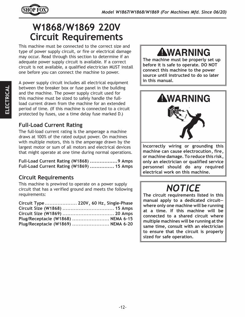
The machine must be properly set up before it is safe to operate. DO NOT connect this machine to the power source until instructed to do so later in this manual.
Incorrectly. wiring. or. grounding. this.machine.can.cause.electrocution,.fire,.or.machine.damage..To.reduce.this.risk,.only.an.electrician.or.qualified.service.personnel. should. do. any. required.electrical.work.on.this.machine.
NOTICE The.circuit. requirements. listed. in. this.manual. apply. to. a. dedicated. circuit—where.only.one.machine.will.be.running.at. a. time.. If. this. machine. will. be.connected. to. a. shared. circuit. where.multiple.machines.will.be.running.at.the.same.time,.consult.with.an.electrician.to. ensure. that. the. circuit. is. properly.sized.for.safe.operation.
-13-
Model W1867/W1868/W1869 (For Machines Mfd. Since 06/20)ELECTRIC
AL
Grounding.RequirementsThis machine MUST be grounded. In the event of certain types of malfunctions or breakdowns, grounding provides a path of least resistance for electric current to travel—in order to reduce the risk of electric shock.
Improper connection of the equipment-grounding wire will increase the risk of electric shock. The wire with green insulation (with/without yellow stripes) is the equipment-grounding wire. If repair or replacement of the power cord or plug is necessary, do not connect the equipment-grounding wire to a live (current carrying) terminal. Check with a qualified electrician or service personnel if you do not understand these grounding requirements, or if you are in doubt about whether the tool is properly grounded. If you ever notice that a cord or plug is damaged or worn, disconnect it from power, and immediately replace it with a new one.
For.220V.Connection
The machine must be properly set up before it is safe to operate. DO NOT connect this machine to the power source until instructed to do so later in this manual.
Extension.CordsWe do not recommend using an extension cord with this machine. Extension cords cause voltage drop, which may damage electrical components and shorten motor life. Voltage drop increases with longer extension cords and smaller gauge sizes (higher gauge numbers indicate smaller sizes).
Any extension cord used with this machine must contain a ground wire, match the required plug and receptacle, and meet the following requirements:
Minimum.Gauge.Size.(W1868)...................... 14.AWGMinimum.Gauge.Size.(W1869)...................... 12.AWGMaximum.Length.(Shorter.is.Better).................50.ft.
No. adapter. should. be. used. with. the.required.plug.. If. the.plug.does.not. fit.the.available.receptacle.or.the.machine.must. be. reconnected. to. a. different.type.of.circuit,.the.reconnection.must.be.made.by.an.electrician.or.qualified.service. personnel. and. it. must. comply.with.all.local.codes.and.ordinances.
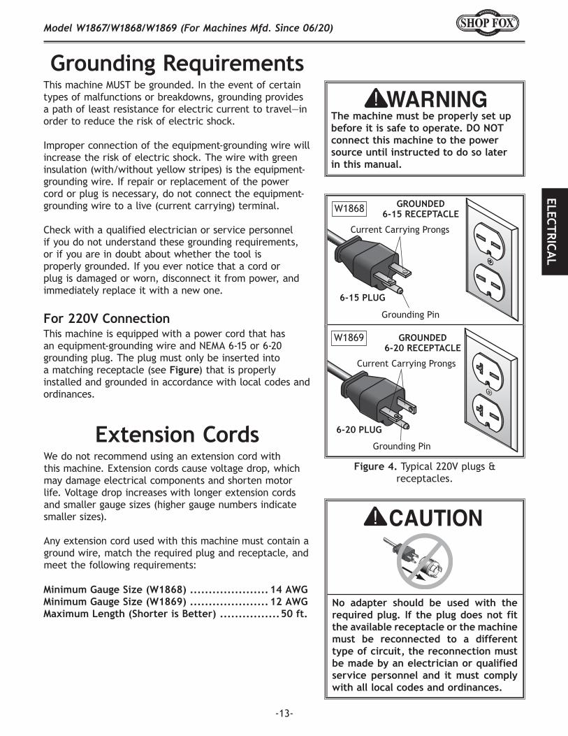
Figure.4. Typical 220V plugs & receptacles.
Grounding Pin
Current Carrying Prongs
6-15 PLUG
GROUNDED6-15 RECEPTACLE
Grounding Pin
Current Carrying Prongs
6-20 PLUG
GROUNDED6-20 RECEPTACLE
This machine is equipped with a power cord that has an equipment-grounding wire and NEMA 6-15 or 6-20 grounding plug. The plug must only be inserted into a matching receptacle (see Figure) that is properly installed and grounded in accordance with local codes and ordinances.
W1869
W1868
-14-
Model W1867/W1868/W1869 (For Machines Mfd. Since 06/20)SE
TUP
SETUPUnpacking
This machine has been carefully packaged for safe transportation. If you notice the machine has been damaged during shipping, please contact your authorized Shop Fox dealer immediately.
Description. Qty• Additional People ..........................................1• Safety Glasses .........................................1 ea.• Wrench or Socket 10mm .................................1• Wrench or Socket 12mm .................................1• Wrench or Socket 5⁄16" ....................................1• Wrench or Socket 3⁄8" .....................................1• Wrench or Socket 1⁄2" .....................................1• Hex Wrench 5mm ..........................................1• Phillips Screwdriver #2 ...................................1
Items.Needed.for.SetupThe following items are needed, but not included, to set up your machine.
Wear safety glasses during entire setup process!
This machine presents serious injury hazards to untrained users. Read through this entire manual to become familiar with the controls and opera-tions before starting the machine!
HEAVY LIFT!Straining or crushing injury may occur from improperly lifting the machine or some of its parts. To reduce this risk, get help from other people and use a forklift (or other lifting equip-ment) rated for weight of machine.
-15-
Model W1867/W1868/W1869 (For Machines Mfd. Since 06/20)SETU
P
Inventory
Figure.5. Boxed parts inventory.
A B
H
I
J
K
C
D E FG
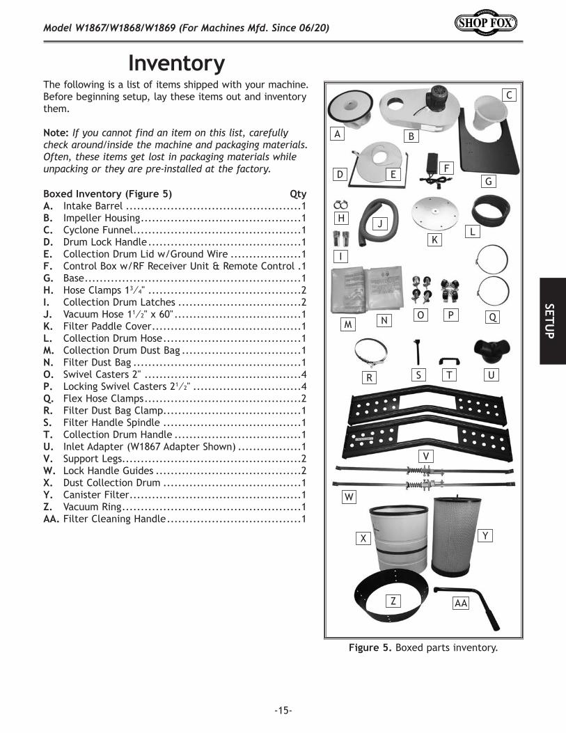
The following is a list of items shipped with your machine. Before beginning setup, lay these items out and inventory them.
Note: If you cannot find an item on this list, carefully check around/inside the machine and packaging materials. Often, these items get lost in packaging materials while unpacking or they are pre-installed at the factory.
Boxed.Inventory.(Figure.5). QtyA. Intake Barrel ...............................................1B. Impeller Housing ...........................................1C. Cyclone Funnel .............................................1D. Drum Lock Handle .........................................1E. Collection Drum Lid w/Ground Wire ...................1F. Control Box w/RF Receiver Unit & Remote Control .1G. Base ..........................................................1H. Hose Clamps 13⁄4" .........................................2I. Collection Drum Latches .................................2J. Vacuum Hose 11⁄2" x 60" ..................................1K. Filter Paddle Cover ........................................1L. Collection Drum Hose .....................................1M. Collection Drum Dust Bag ................................1N. Filter Dust Bag .............................................1O. Swivel Casters 2" ..........................................4P. Locking Swivel Casters 21⁄2" .............................4Q. Flex Hose Clamps ..........................................2R. Filter Dust Bag Clamp.....................................1S. Filter Handle Spindle .....................................1T. Collection Drum Handle ..................................1U. Inlet Adapter (W1867 Adapter Shown) .................1V. Support Legs................................................2W. Lock Handle Guides .......................................2X. Dust Collection Drum .....................................1Y. Canister Filter ..............................................1Z. Vacuum Ring ................................................1AA. Filter Cleaning Handle ....................................1
TSR
QPON
L
M
YX
W
V
U
Z AA
-16-
Model W1867/W1868/W1869 (For Machines Mfd. Since 06/20)SE
TUP
Figure.6. Hardware/fasteners.
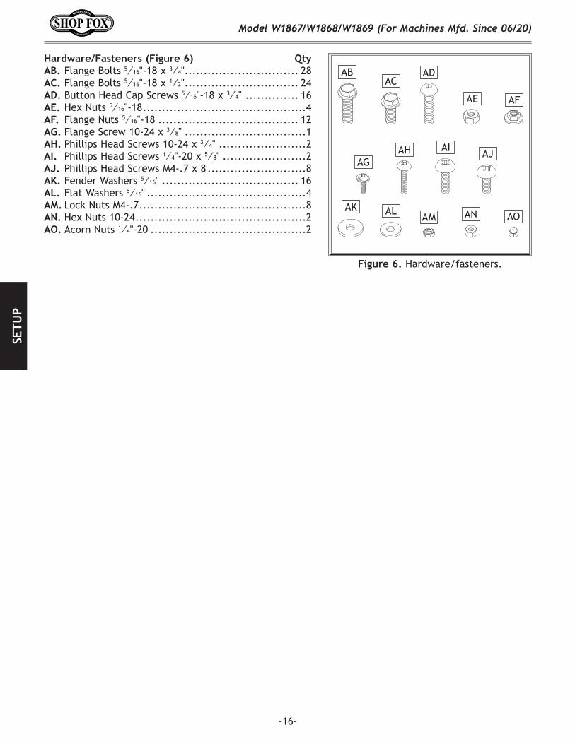
Hardware/Fasteners.(Figure.6). QtyAB. Flange Bolts 5⁄16"-18 x 3⁄4" .............................. 28AC. Flange Bolts 5⁄16"-18 x 1⁄2" .............................. 24AD. Button Head Cap Screws 5⁄16"-18 x 3⁄4" .............. 16AE. Hex Nuts 5⁄16"-18 ...........................................4AF. Flange Nuts 5⁄16"-18 ..................................... 12AG. Flange Screw 10-24 x 3⁄8" ................................1AH. Phillips Head Screws 10-24 x 3⁄4" .......................2AI. Phillips Head Screws 1⁄4"-20 x 5⁄8" ......................2AJ. Phillips Head Screws M4-.7 x 8 ..........................8AK. Fender Washers 5⁄16" .................................... 16AL. Flat Washers 5⁄16" ..........................................4AM. Lock Nuts M4-.7 ............................................8AN. Hex Nuts 10-24 .............................................2AO. Acorn Nuts 1⁄4"-20 .........................................2
ABAC
AOANAMALAK
AJAIAH
AG
AFAE
AD
-17-
Model W1867/W1868/W1869 (For Machines Mfd. Since 06/20)SETU
P
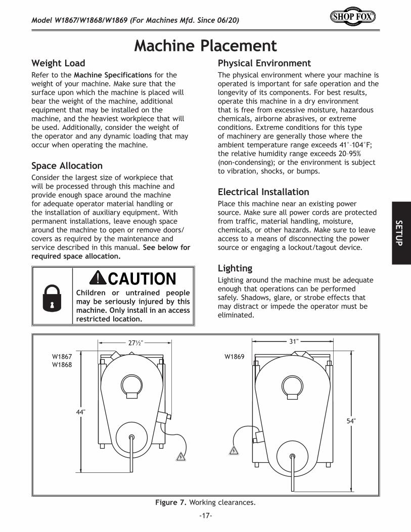
Figure.7. Working clearances.
Machine.Placement
31"
54"
27½"
44"
W1867W1868
W1869
Weight.LoadRefer to the Machine.Specifications for the weight of your machine. Make sure that the surface upon which the machine is placed will bear the weight of the machine, additional equipment that may be installed on the machine, and the heaviest workpiece that will be used. Additionally, consider the weight of the operator and any dynamic loading that may occur when operating the machine.
Space.AllocationConsider the largest size of workpiece that will be processed through this machine and provide enough space around the machine for adequate operator material handling or the installation of auxiliary equipment. With permanent installations, leave enough space around the machine to open or remove doors/covers as required by the maintenance and service described in this manual. See.below.for.required.space.allocation.
Physical.EnvironmentThe physical environment where your machine is operated is important for safe operation and the longevity of its components. For best results, operate this machine in a dry environment that is free from excessive moisture, hazardous chemicals, airborne abrasives, or extreme conditions. Extreme conditions for this type of machinery are generally those where the ambient temperature range exceeds 41°–104°F; the relative humidity range exceeds 20–95% (non-condensing); or the environment is subject to vibration, shocks, or bumps.
Electrical.InstallationPlace this machine near an existing power source. Make sure all power cords are protected from traffic, material handling, moisture, chemicals, or other hazards. Make sure to leave access to a means of disconnecting the power source or engaging a lockout/tagout device.
LightingLighting around the machine must be adequate enough that operations can be performed safely. Shadows, glare, or strobe effects that may distract or impede the operator must be eliminated.
Children. or. untrained. people.may.be.seriously. injured.by.this.machine..Only.install.in.an.access.restricted.location.
-18-
Model W1867/W1868/W1869 (For Machines Mfd. Since 06/20)SE
TUP
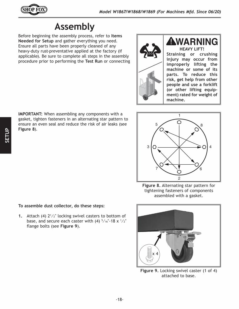
AssemblyBefore beginning the assembly process, refer to Items.Needed.for.Setup and gather everything you need. Ensure all parts have been properly cleaned of any heavy-duty rust-preventative applied at the factory (if applicable). Be sure to complete all steps in the assembly procedure prior to performing the Test.Run.or connecting the machine to power.
HEAVY LIFT!Straining or crushing injury may occur from improperly lifting the machine or some of its parts. To reduce this risk, get help from other people and use a forklift (or other lifting equip-ment) rated for weight of machine.
IMPORTANT: When assembling any components with a gasket, tighten fasteners in an alternating star pattern to ensure an even seal and reduce the risk of air leaks (see Figure.8).
1
2
3 4
5
67
8
Figure.8. Alternating star pattern for tightening fasteners of components
assembled with a gasket.
Figure.9. Locking swivel caster (1 of 4) attached to base.
x 4
To.assemble.dust.collector,.do.these.steps:
1. Attach (4) 21⁄2" locking swivel casters to bottom of base, and secure each caster with (4) 5⁄16"-18 x 1⁄2" flange bolts (see Figure.9).
-19-
Model W1867/W1868/W1869 (For Machines Mfd. Since 06/20)SETU
P
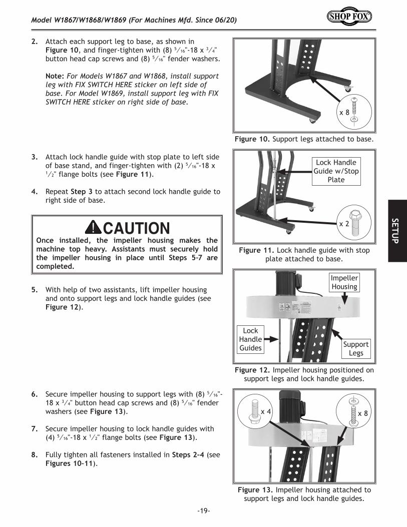
2. Attach each support leg to base, as shown in Figure.10, and finger-tighten with (8) 5⁄16"-18 x 3⁄4" button head cap screws and (8) 5⁄16" fender washers.
Note: For Models W1867 and W1868, install support leg with FIX SWITCH HERE sticker on left side of base. For Model W1869, install support leg with FIX SWITCH HERE sticker on right side of base.
Figure.10. Support legs attached to base.
x 8
3. Attach lock handle guide with stop plate to left side of base stand, and finger-tighten with (2) 5⁄16"-18 x 1⁄2" flange bolts (see Figure.11).
4. Repeat Step.3 to attach second lock handle guide to right side of base.
Once. installed,. the. impeller. housing. makes. the.machine. top. heavy.. Assistants. must. securely. hold.the. impeller. housing. in. place. until. Steps. 5–7. are.completed.
5. With help of two assistants, lift impeller housing and onto support legs and lock handle guides (see Figure.12).
Figure.12. Impeller housing positioned on support legs and lock handle guides.
Impeller Housing
Lock Handle Guides Support
Legs
6. Secure impeller housing to support legs with (8) 5⁄16"-18 x 3⁄4" button head cap screws and (8) 5⁄16" fender washers (see Figure.13).
7. Secure impeller housing to lock handle guides with (4) 5⁄16"-18 x 1⁄2" flange bolts (see Figure.13).
8. Fully tighten all fasteners installed in Steps.2–4 (see Figures.10–11).
Figure.13. Impeller housing attached to support legs and lock handle guides.
x 8x 4
Figure.11. Lock handle guide with stop plate attached to base.
Lock Handle Guide w/Stop
Plate
x 2
-20-
Model W1867/W1868/W1869 (For Machines Mfd. Since 06/20)SE
TUP
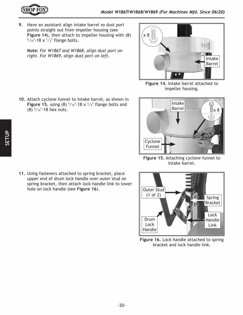
9. Have an assistant align intake barrel so dust port points straight out from impeller housing (see Figure.14), then attach to impeller housing with (8) 5⁄16"-18 x 1⁄2" flange bolts.
Note: For W1867 and W1868, align dust port on right. For W1869, align dust port on left.
Figure.14. Intake barrel attached to impeller housing.
10. Attach cyclone funnel to intake barrel, as shown in Figure.15, using (8) 5⁄16"-18 x 3⁄4" flange bolts and (8) 5⁄16"-18 hex nuts.
x 8
Intake Barrel
Figure.15. Attaching cyclone funnel to intake barrel.
x 8
Intake Barrel
Cyclone Funnel
11. Using fasteners attached to spring bracket, place upper end of drum lock handle over outer stud on spring bracket, then attach lock handle link to lower hole on lock handle (see Figure.16).
Figure.16. Lock handle attached to spring bracket and lock handle link.
Outer Stud (1 of 2) Spring
Bracket
Lock Handle
LinkDrum Lock
Handle
-21-
Model W1867/W1868/W1869 (For Machines Mfd. Since 06/20)SETU
P
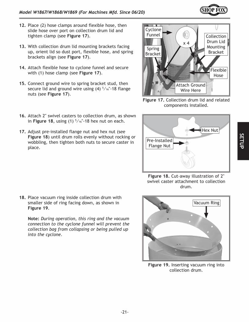
12. Place (2) hose clamps around flexible hose, then slide hose over port on collection drum lid and tighten clamp (see Figure.17).
13. With collection drum lid mounting brackets facing up, orient lid so dust port, flexible hose, and spring brackets align (see Figure.17).
14. Attach flexible hose to cyclone funnel and secure with (1) hose clamp (see Figure.17).
15. Connect ground wire to spring bracket stud, then secure lid and ground wire using (4) 5⁄16"-18 flange nuts (see Figure.17).
16. Attach 2" swivel casters to collection drum, as shown in Figure.18, using (1) 5⁄16"-18 hex nut on each.
17. Adjust pre-installed flange nut and hex nut (see Figure.18) until drum rolls evenly without rocking or wobbling, then tighten both nuts to secure caster in place.
Figure.17. Collection drum lid and related components installed.
Spring Bracket
Attach Ground Wire Here
x 4
Cyclone Funnel
Flexible Hose
Collection Drum Lid Mounting Bracket
Figure.18. Cut-away illustration of 2" swivel caster attachment to collection
drum.
Hex Nut
Pre-Installed Flange Nut
18. Place vacuum ring inside collection drum with smaller side of ring facing down, as shown in Figure.19.
Note: During operation, this ring and the vacuum connection to the cyclone funnel will prevent the collection bag from collapsing or being pulled up into the cyclone.
Figure.19. Inserting vacuum ring into collection drum.
Vacuum Ring
-22-
Model W1867/W1868/W1869 (For Machines Mfd. Since 06/20)SE
TUP
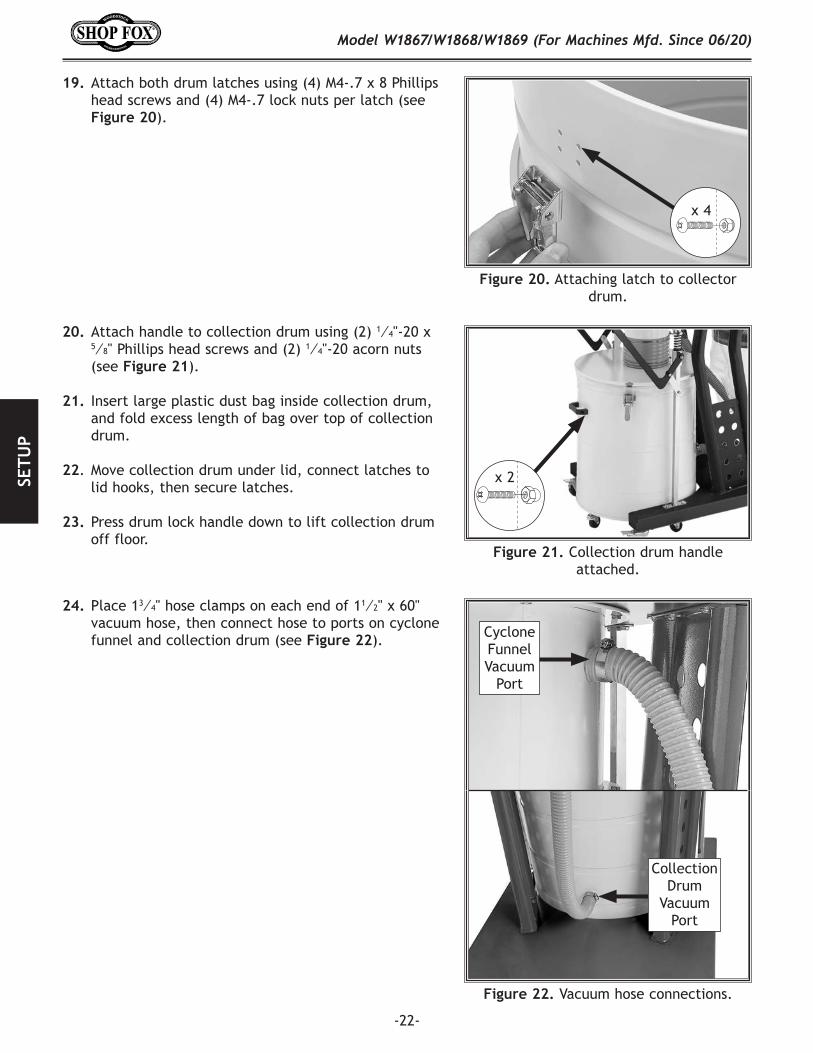
19. Attach both drum latches using (4) M4-.7 x 8 Phillips head screws and (4) M4-.7 lock nuts per latch (see Figure.20).
Figure.20. Attaching latch to collector drum.
x 4
20. Attach handle to collection drum using (2) 1⁄4"-20 x 5⁄8" Phillips head screws and (2) 1⁄4"-20 acorn nuts (see Figure.21).
21. Insert large plastic dust bag inside collection drum, and fold excess length of bag over top of collection drum.
22. Move collection drum under lid, connect latches to lid hooks, then secure latches.
23. Press drum lock handle down to lift collection drum off floor.
Figure.21. Collection drum handle attached.
x 2
24. Place 13⁄4" hose clamps on each end of 11⁄2" x 60" vacuum hose, then connect hose to ports on cyclone funnel and collection drum (see Figure.22).
Figure.22. Vacuum hose connections.
Collection Drum
Vacuum Port
Cyclone Funnel Vacuum
Port
-23-
Model W1867/W1868/W1869 (For Machines Mfd. Since 06/20)SETU
P
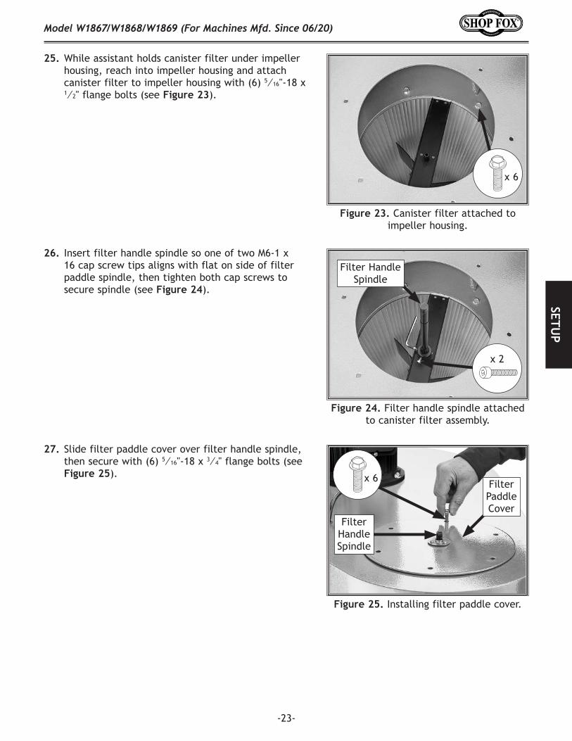
25. While assistant holds canister filter under impeller housing, reach into impeller housing and attach canister filter to impeller housing with (6) 5⁄16"-18 x 1⁄2" flange bolts (see Figure.23).
Figure.23. Canister filter attached to impeller housing.
x 6
26. Insert filter handle spindle so one of two M6-1 x 16 cap screw tips aligns with flat on side of filter paddle spindle, then tighten both cap screws to secure spindle (see Figure.24).
27. Slide filter paddle cover over filter handle spindle, then secure with (6) 5⁄16"-18 x 3⁄4" flange bolts (see Figure.25).
Figure.25. Installing filter paddle cover.
x 6
Filter Handle Spindle
Filter Paddle Cover
Figure.24. Filter handle spindle attached to canister filter assembly.
Filter Handle Spindle
x 2
-24-
Model W1867/W1868/W1869 (For Machines Mfd. Since 06/20)SE
TUP
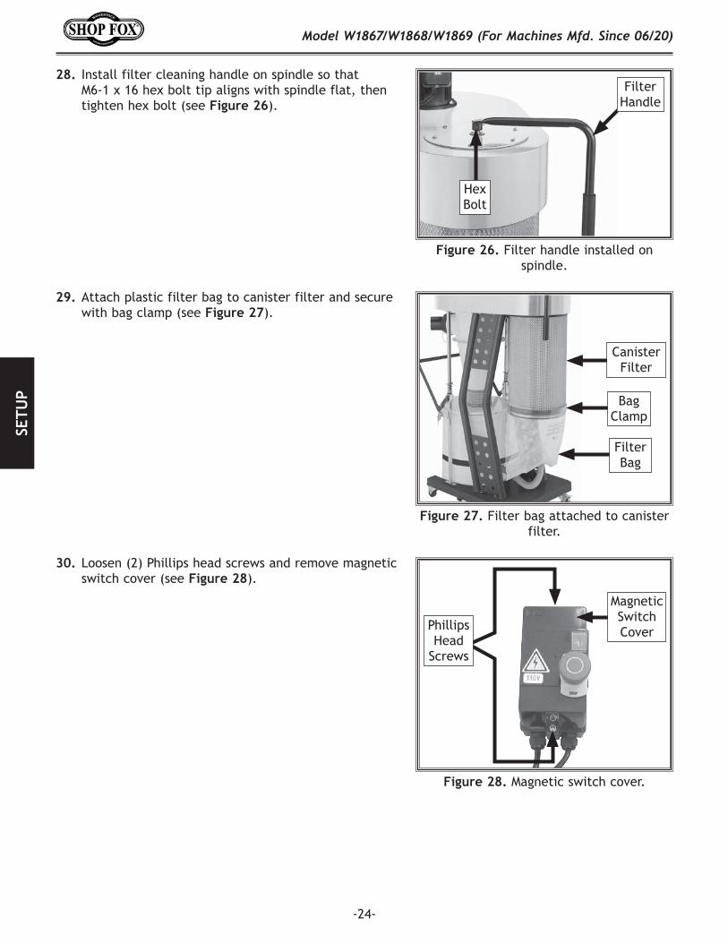
29. Attach plastic filter bag to canister filter and secure with bag clamp (see Figure.27).
30. Loosen (2) Phillips head screws and remove magnetic switch cover (see Figure.28).
Figure.27. Filter bag attached to canister filter.
Filter Bag
Canister Filter
Bag Clamp
Figure.28. Magnetic switch cover.
Phillips Head
Screws
Magnetic Switch Cover
28. Install filter cleaning handle on spindle so that M6-1 x 16 hex bolt tip aligns with spindle flat, then tighten hex bolt (see Figure.26).
Figure.26. Filter handle installed on spindle.
Hex Bolt
Filter Handle
-25-
Model W1867/W1868/W1869 (For Machines Mfd. Since 06/20)SETU
P
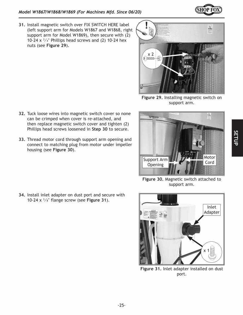
31. Install magnetic switch over FIX SWITCH HERE label (left support arm for Models W1867 and W1868, right support arm for Model W1869), then secure with (2) 10-24 x 3⁄4" Phillips head screws and (2) 10-24 hex nuts (see Figure.29).
Figure.29. Installing magnetic switch on support arm.
x 2
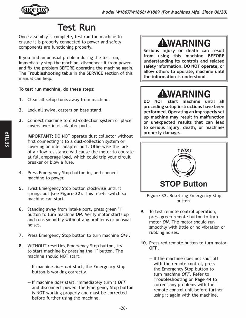
32. Tuck loose wires into magnetic switch cover so none can be crimped when cover is re-attached, and then replace magnetic switch cover and tighten (2) Phillips head screws loosened in Step.30 to secure.
33. Thread motor cord through support arm opening and connect to matching plug from motor under impeller housing (see Figure.30).
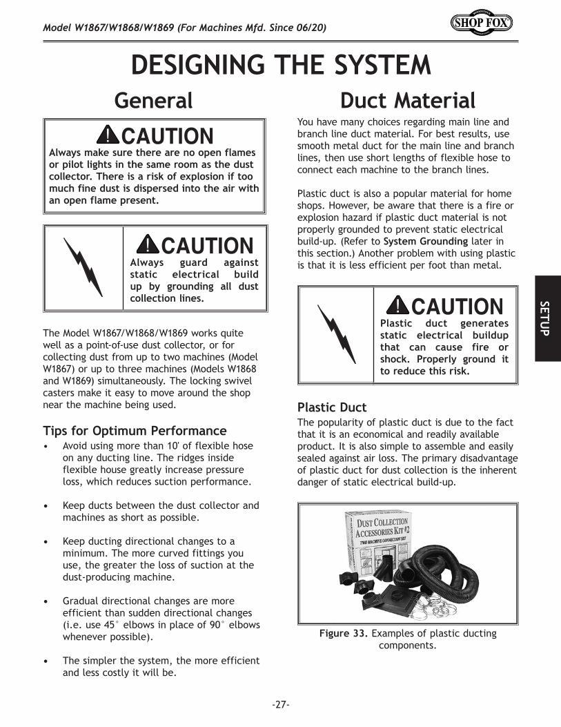
34. Install inlet adapter on dust port and secure with 10-24 x 3⁄8" flange screw (see Figure.31).
Figure.30. Magnetic switch attached to support arm.
Motor Cord
Support Arm Opening
x 1
Inlet Adapter
Figure.31. Inlet adapter installed on dust port.
-26-
Model W1867/W1868/W1869 (For Machines Mfd. Since 06/20)SE
TUP
Test.Run
Serious. injury. or. death. can. result.from. using. this. machine. BEFORE.understanding. its. controls. and. related.safety.information..DO.NOT.operate,.or.allow.others.to.operate,.machine.until.the.information.is.understood..
DO. NOT. start. machine. until. all.preceding.setup.instructions.have.been.performed..Operating.an.improperly.set.up.machine.may. result. in.malfunction.or. unexpected. results. that. can. lead.to. serious. injury,. death,. or. machine/property.damage.
Once assembly is complete, test run the machine to ensure it is properly connected to power and safety components are functioning properly.
If you find an unusual problem during the test run, immediately stop the machine, disconnect it from power, and fix the problem BEFORE operating the machine again. The Troubleshooting table in the SERVICE section of this manual can help.
To.test.run.machine,.do.these.steps:
1. Clear all setup tools away from machine.
2. Lock all swivel casters on base stand.
3. Connect machine to dust-collection system or place covers over inlet adapter ports.
IMPORTANT: DO NOT operate dust collector without first connecting it to a dust-collection system or covering an inlet adapter port. Otherwise the lack of airflow resistance will cause the motor to operate at full amperage load, which could trip your circuit breaker or blow a fuse.
4. Press Emergency Stop button in, and connect machine to power.
5. Twist Emergency Stop button clockwise until it springs out (see Figure.32). This resets switch so machine can start.
6. Standing away from intake port, press green "I" button to turn machine ON. Verify motor starts up and runs smoothly without any problems or unusual noises.
7. Press Emergency Stop button to turn machine OFF.
8. WITHOUT resetting Emergency Stop button, try to start machine by pressing the "I" button. The machine should NOT start.
— If machine does not start, the Emergency Stop button is working correctly.
— If machine does start, immediately turn it OFF and disconnect power. The Emergency Stop button is NOT working properly and must be corrected before further using the machine.
9. To test remote control operation, press green remote button to turn motor ON. The motor should run smoothly with little or no vibration or rubbing noises.
10. Press red remote button to turn motor OFF.
— If the machine does not shut off with the remote control, press the Emergency Stop button to turn machine OFF. Refer to Troubleshooting on Page.44 to correct any problems with the remote control unit before further using it again with the machine.
Figure.32. Resetting Emergency Stop button.
-27-
Model W1867/W1868/W1869 (For Machines Mfd. Since 06/20)SETU
P
DESIGNING.THE.SYSTEMGeneral Duct.Material
Plastic.Duct
Figure.33. Examples of plastic ducting components.
The Model W1867/W1868/W1869 works quite well as a point-of-use dust collector, or for collecting dust from up to two machines (Model W1867) or up to three machines (Models W1868 and W1869) simultaneously. The locking swivel casters make it easy to move around the shop near the machine being used.
• Avoid using more than 10' of flexible hose on any ducting line. The ridges inside flexible house greatly increase pressure loss, which reduces suction performance.
• Keep ducts between the dust collector and machines as short as possible.
• Keep ducting directional changes to a minimum. The more curved fittings you use, the greater the loss of suction at the dust-producing machine.
• Gradual directional changes are more efficient than sudden directional changes (i.e. use 45° elbows in place of 90° elbows whenever possible).
• The simpler the system, the more efficient and less costly it will be.
Tips.for.Optimum.Performance
You have many choices regarding main line and branch line duct material. For best results, use smooth metal duct for the main line and branch lines, then use short lengths of flexible hose to connect each machine to the branch lines.
Plastic duct is also a popular material for home shops. However, be aware that there is a fire or explosion hazard if plastic duct material is not properly grounded to prevent static electrical build-up. (Refer to System.Grounding later in this section.) Another problem with using plastic is that it is less efficient per foot than metal.
The popularity of plastic duct is due to the fact that it is an economical and readily available product. It is also simple to assemble and easily sealed against air loss. The primary disadvantage of plastic duct for dust collection is the inherent danger of static electrical build-up.
Always. guard. against.static. electrical. build.up. by. grounding. all. dust.collection.lines.
Plastic. duct. generates.static. electrical. buildup.that. can. cause. fire. or.shock.. Properly. ground. it.to.reduce.this.risk.
Always.make.sure.there.are.no.open.flames.or.pilot.lights.in.the.same.room.as.the.dust.collector..There.is.a.risk.of.explosion.if.too.much.fine.dust.is.dispersed.into.the.air.with.an.open.flame.present.
-28-
Model W1867/W1868/W1869 (For Machines Mfd. Since 06/20)SE
TUP
Figure 35. Example of flexible metal duct.
Flexible.DuctMetal.Duct
Figure 34. Examples of smooth metal duct and components.
Advantages of smooth metal duct is its conductivity, efficiency, and that it does not contribute to static electrical charge build-up. However, static charges are still produced when dust particles strike other dust particles as they move through the duct. Since metal duct is a conductor, it can be grounded quite easily to dissipate any static electrical charges.
There are a number of options when it comes to metal duct, but metal duct that is specially manufactured for dust collection is the best choice. When selecting your metal duct, choose high quality metal duct with smooth welded internal seams that will minimize airflow resistance. This type of duct usually connects to other ducts or elbows with a simple, self-sealing clamp, is very quick and easy to assemble, and can be readily dismantled and re-installed in a different configuration. This is especially important if you ever need to change things around in your shop or add more tools.
Avoid inferior metal duct that requires you to cut it to length and snap it together. This type of duct is time consuming to install because it requires you to seal all the seams with silicone and screw the components on the ends with sheet metal screws. Another disadvantage is the rough internal seams and crimped ends that unavoidably increase static pressure loss.
Flexible hose is generally used for short runs, small shops and at rigid duct-to-tool connections. There are many different types of flex hose on the market today. These are manufactured from materials such as polyethylene, PVC, cloth hose dipped in rubber and even metal, including steel and aluminum.
The superior choice here is metal flex hose that is designed to be flexible, yet be as smooth as possible inside to reduce static pressure loss.
There are also many kinds of pure plastic flexible hose, such as non-perforated drainage type hose and dryer vent hose. Drainage type hose, while being economical, does not quite have the flexibility required for dust collection. The inside of the duct is also deeply corrugated and can increase the static pressure loss by as much as 50% over smooth wall duct. Dryer vent hose, while being completely flexible, is non-resistant to abrasion and has a tendency to collapse in a negative pressure system. We DO NOT recommend using dryer vent hose in your dust collection system.
If using flex-hose, you should choose one of the many types that are designed specifically for the movement of solid particles, i.e. dust, grains, and plastics. However, the cost of specifically designed flexible duct can vary greatly. Polyethylene hose is well suited for the removal of particulate matter, especially sawdust, since it is durable and completely flexible. Polyethylene is also very economical and available in a wide variety of diameters and lengths for most applications.
-29-
Model W1867/W1868/W1869 (For Machines Mfd. Since 06/20)SETU
P
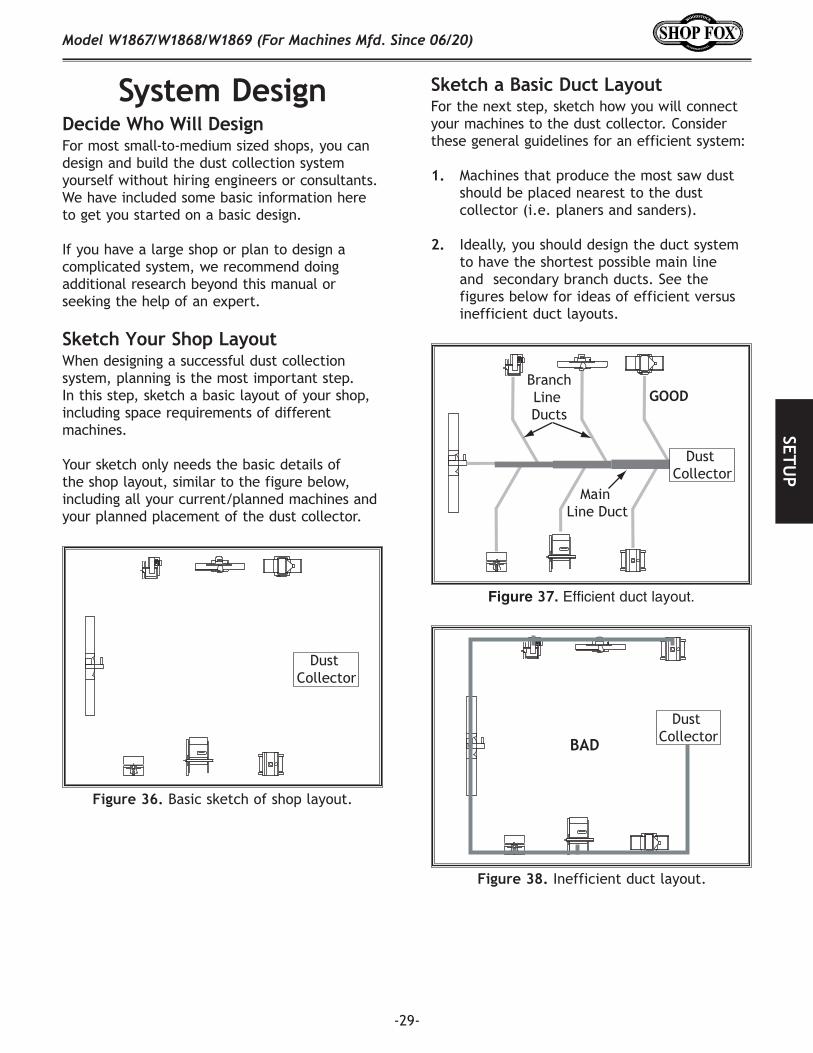
System.DesignDecide.Who.Will.Design
Dust Collector
Figure 36. Basic sketch of shop layout.
Sketch.Your.Shop.Layout
Figure.38. Inefficient duct layout.
BAD
Dust Collector
Figure 37. Efficient duct layout.
Main Line Duct
BranchLine Ducts
GOOD
Dust Collector
Sketch.a.Basic.Duct.Layout
For most small-to-medium sized shops, you can design and build the dust collection system yourself without hiring engineers or consultants. We have included some basic information here to get you started on a basic design.
If you have a large shop or plan to design a complicated system, we recommend doing additional research beyond this manual or seeking the help of an expert.
When designing a successful dust collection system, planning is the most important step. In this step, sketch a basic layout of your shop, including space requirements of different machines.
Your sketch only needs the basic details of the shop layout, similar to the figure below, including all your current/planned machines and your planned placement of the dust collector.
For the next step, sketch how you will connect your machines to the dust collector. Consider these general guidelines for an efficient system:
1. Machines that produce the most saw dust should be placed nearest to the dust collector (i.e. planers and sanders).
2. Ideally, you should design the duct system to have the shortest possible main line and secondary branch ducts. See the figures below for ideas of efficient versus inefficient duct layouts.
-30-
Model W1867/W1868/W1869 (For Machines Mfd. Since 06/20)SE
TUP
Determine.Required.CFMs
Figure.41. CFM requirements labeled for each machine.
400
400
600
850400
250
100
Table Saw
Planer/Moulder
MiterSaw
Jointer Sander
PlanerShaper
Dust Collector
3. Directional changes should be kept to a minimum. The more directional change fittings you use directly increases the overall resistance to airflow.
4. Gradual directional changes are more efficient than sudden directional changes (i.e. use the largest corner radius possible when changing hose or pipe direction).
5. Each individual branch line should have a blast gate immediately after the branch to control suction from one machine to another.
6. The simpler the system, the more efficient and less costly it will be.
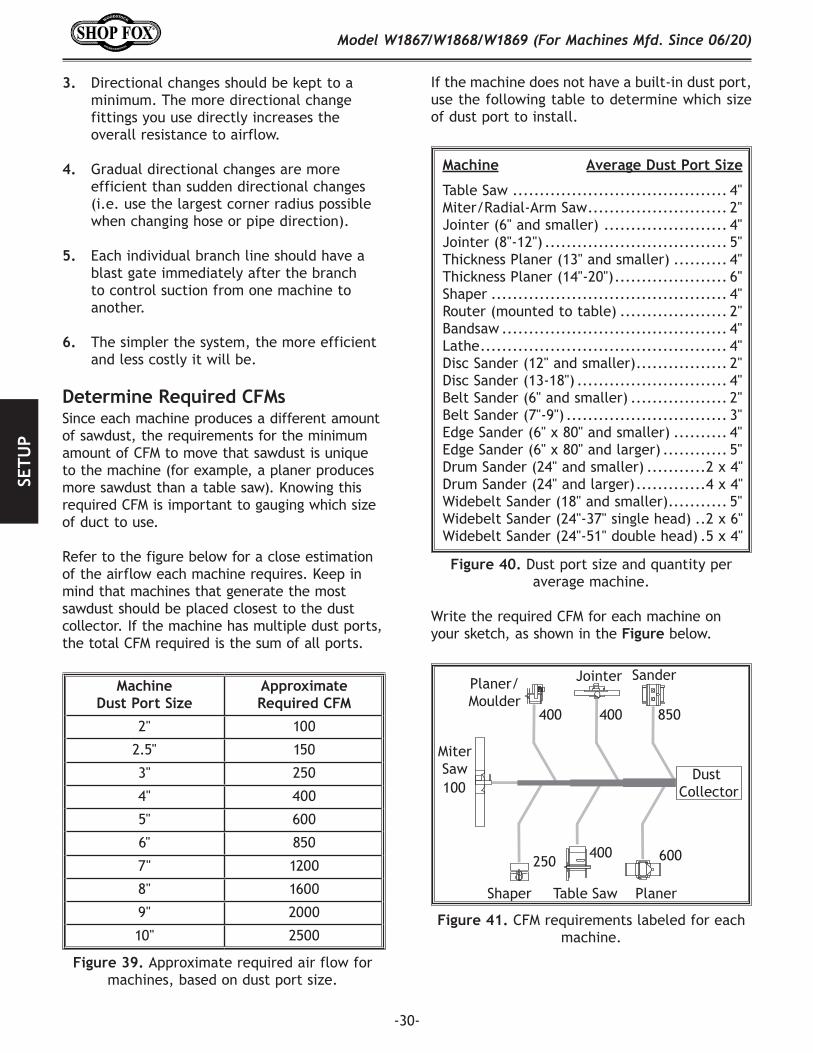
Since each machine produces a different amount of sawdust, the requirements for the minimum amount of CFM to move that sawdust is unique to the machine (for example, a planer produces more sawdust than a table saw). Knowing this required CFM is important to gauging which size of duct to use.
Refer to the figure below for a close estimation of the airflow each machine requires. Keep in mind that machines that generate the most sawdust should be placed closest to the dust collector. If the machine has multiple dust ports, the total CFM required is the sum of all ports.
If the machine does not have a built-in dust port, use the following table to determine which size of dust port to install.
Figure.40..Dust port size and quantity per average machine.
Machine..................Average.Dust.Port.Size
Table Saw ........................................ 4"Miter/Radial-Arm Saw .......................... 2"Jointer (6" and smaller) ....................... 4"Jointer (8"-12") .................................. 5"Thickness Planer (13" and smaller) .......... 4"Thickness Planer (14"-20") ..................... 6"Shaper ............................................ 4"Router (mounted to table) .................... 2"Bandsaw .......................................... 4"Lathe .............................................. 4"Disc Sander (12" and smaller) ................. 2"Disc Sander (13-18") ............................ 4"Belt Sander (6" and smaller) .................. 2"Belt Sander (7"-9") .............................. 3"Edge Sander (6" x 80" and smaller) .......... 4"Edge Sander (6" x 80" and larger) ............ 5"Drum Sander (24" and smaller) ...........2 x 4"Drum Sander (24" and larger) .............4 x 4"Widebelt Sander (18" and smaller) ........... 5"Widebelt Sander (24"-37" single head) ..2 x 6"Widebelt Sander (24"-51" double head) .5 x 4"
Write the required CFM for each machine on your sketch, as shown in the Figure below.
Machine.Dust.Port.Size
Approximate.Required.CFM
2" 100
2.5" 150
3" 250
4" 400
5" 600
6" 850
7" 1200
8" 1600
9" 2000
10" 2500
Figure.39..Approximate required air flow for machines, based on dust port size.
-31-
Model W1867/W1868/W1869 (For Machines Mfd. Since 06/20)SETU
P
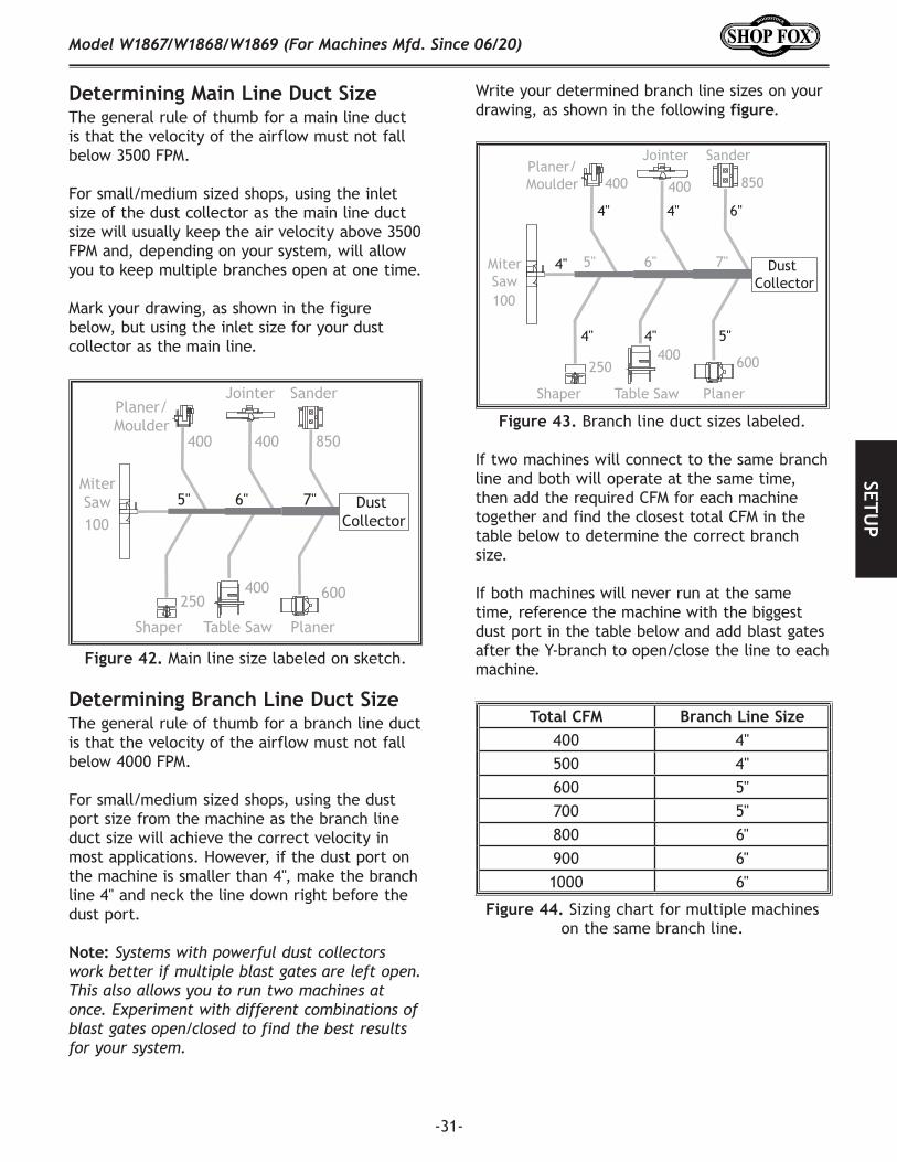
Figure.42. Main line size labeled on sketch.
400
400
600
850400
250
100
5" 6" 7"
Table Saw
Planer/Moulder
MiterSaw
Jointer Sander
PlanerShaper
Dust Collector
Determining.Main.Line.Duct.Size
Determining.Branch.Line.Duct.Size
The general rule of thumb for a main line duct is that the velocity of the airflow must not fall below 3500 FPM.
For small/medium sized shops, using the inlet size of the dust collector as the main line duct size will usually keep the air velocity above 3500 FPM and, depending on your system, will allow you to keep multiple branches open at one time.
Mark your drawing, as shown in the figure below, but using the inlet size for your dust collector as the main line.
The general rule of thumb for a branch line duct is that the velocity of the airflow must not fall below 4000 FPM.
For small/medium sized shops, using the dust port size from the machine as the branch line duct size will achieve the correct velocity in most applications. However, if the dust port on the machine is smaller than 4", make the branch line 4" and neck the line down right before the dust port.
Note:.Systems with powerful dust collectors work better if multiple blast gates are left open. This also allows you to run two machines at once. Experiment with different combinations of blast gates open/closed to find the best results for your system.
Figure.43. Branch line duct sizes labeled.
400
400
600
850400
250
100
4"
4"
4" 6"
4" 4" 5"
5" 6" 7"
Table Saw
MiterSaw
Jointer Sander
PlanerShaper
Planer/Moulder
Dust Collector
Figure.44. Sizing chart for multiple machines on the same branch line.
If two machines will connect to the same branch line and both will operate at the same time, then add the required CFM for each machine together and find the closest total CFM in the table below to determine the correct branch size.
If both machines will never run at the same time, reference the machine with the biggest dust port in the table.below and add blast gates after the Y-branch to open/close the line to each machine.
Total.CFM Branch.Line.Size400 4"500 4"600 5"700 5"800 6"900 6"1000 6"
Write your determined branch line sizes on your drawing, as shown in the following figure.
-32-
Model W1867/W1868/W1869 (For Machines Mfd. Since 06/20)SE
TUP Calculating.Duct.Resistance
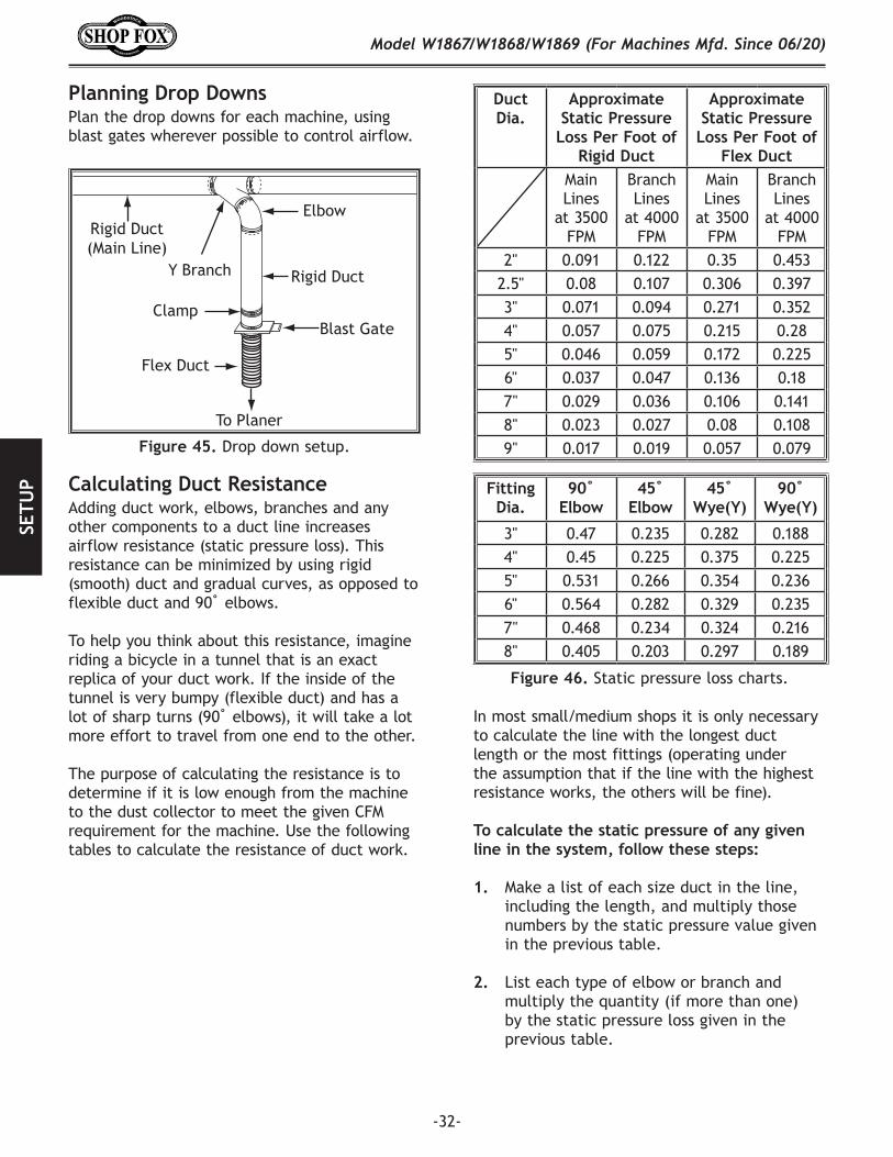
To Planer
Blast Gate
Flex Duct
Rigid Duct
Rigid Duct (Main Line)
Elbow
Clamp
Y Branch
Figure.45. Drop down setup.
Planning.Drop.DownsPlan the drop downs for each machine, using blast gates wherever possible to control airflow.
Adding duct work, elbows, branches and any other components to a duct line increases airflow resistance (static pressure loss). This resistance can be minimized by using rigid (smooth) duct and gradual curves, as opposed to flexible duct and 90˚ elbows.
To help you think about this resistance, imagine riding a bicycle in a tunnel that is an exact replica of your duct work. If the inside of the tunnel is very bumpy (flexible duct) and has a lot of sharp turns (90˚ elbows), it will take a lot more effort to travel from one end to the other.
The purpose of calculating the resistance is to determine if it is low enough from the machine to the dust collector to meet the given CFM requirement for the machine. Use the following tables to calculate the resistance of duct work.
Figure.46..Static pressure loss charts.
Duct.Dia.
Approximate.Static.Pressure.
Loss.Per.Foot.of.Rigid.Duct
Approximate.Static.Pressure.
Loss.Per.Foot.of.Flex.Duct
Main Lines
at 3500 FPM
Branch Lines
at 4000 FPM
Main Lines
at 3500 FPM
Branch Lines
at 4000 FPM
2" 0.091 0.122 0.35 0.4532.5" 0.08 0.107 0.306 0.3973" 0.071 0.094 0.271 0.3524" 0.057 0.075 0.215 0.285" 0.046 0.059 0.172 0.2256" 0.037 0.047 0.136 0.187" 0.029 0.036 0.106 0.1418" 0.023 0.027 0.08 0.1089" 0.017 0.019 0.057 0.079
Fitting.Dia.
90˚.Elbow
45̊ .Elbow
45̊ ..Wye(Y)
90˚.Wye(Y)
3" 0.47 0.235 0.282 0.1884" 0.45 0.225 0.375 0.2255" 0.531 0.266 0.354 0.2366" 0.564 0.282 0.329 0.2357" 0.468 0.234 0.324 0.2168" 0.405 0.203 0.297 0.189
In most small/medium shops it is only necessary to calculate the line with the longest duct length or the most fittings (operating under the assumption that if the line with the highest resistance works, the others will be fine).
To.calculate.the.static.pressure.of.any.given.line.in.the.system,.follow.these.steps:
1. Make a list of each size duct in the line, including the length, and multiply those numbers by the static pressure value given in the previous table.
2. List each type of elbow or branch and multiply the quantity (if more than one) by the static pressure loss given in the previous table.
-33-
Model W1867/W1868/W1869 (For Machines Mfd. Since 06/20)SETU
P
Figure.48. Totaling static pressure numbers.
Main Line6" Rigid Duct (0.037) at 20' ........ 0.740
Branch Line4" Rigid Duct (0.075) at 10' ........ 0.7504" Flex Duct (0.28) at 5' ................ 1.400
Elbows/Branches6" 45˚ Y-Branch ........................ 0.3294" 45˚ Elbow................................ 0.225
Additional FactorsSeasoned Filter ........................ 1.000
Total Static Pressure Loss ................ 4.444
Figure.47. Additional factors affecting static pressure.
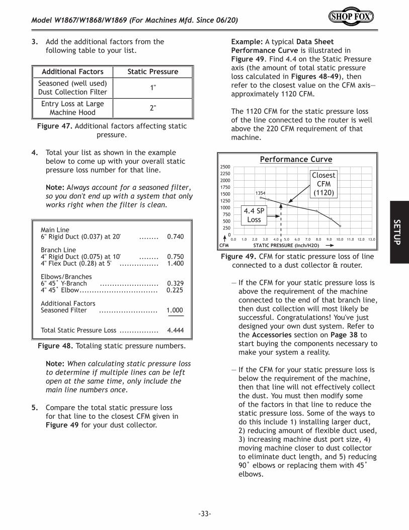
Example: A typical Data.Sheet.Performance.Curve is illustrated in Figure.49. Find 4.4 on the Static Pressure axis (the amount of total static pressure loss calculated in Figures.48–49), then refer to the closest value on the CFM axis—approximately 1120 CFM.
The 1120 CFM for the static pressure loss of the line connected to the router is well above the 220 CFM requirement of that machine.
— If the CFM for your static pressure loss is above the requirement of the machine connected to the end of that branch line, then dust collection will most likely be successful. Congratulations! You've just designed your own dust system. Refer to the Accessories section on Page.38 to start buying the components necessary to make your system a reality.
— If the CFM for your static pressure loss is below the requirement of the machine, then that line will not effectively collect the dust. You must then modify some of the factors in that line to reduce the static pressure loss. Some of the ways to do this include 1) installing larger duct, 2) reducing amount of flexible duct used, 3) increasing machine dust port size, 4) moving machine closer to dust collector to eliminate duct length, and 5) reducing 90˚ elbows or replacing them with 45˚ elbows.
3. Add the additional factors from the following table to your list.
Additional.Factors Static.Pressure
Seasoned (well used) Dust Collection Filter 1"
Entry Loss at Large Machine Hood 2"
4. Total your list as shown in the example below to come up with your overall static pressure loss number for that line.
Note: Always account for a seasoned filter, so you don't end up with a system that only works right when the filter is clean.
Note: When calculating static pressure loss to determine if multiple lines can be left open at the same time, only include the main line numbers once.
5. Compare the total static pressure loss for that line to the closest CFM given in Figure.49 for your dust collector.
Figure.49. CFM for static pressure loss of line connected to a dust collector & router.
Performance Curve2500225020001750150012501000750500250
00.0 1.0 2.0 3.0 4.0 5.0 6.0 7.0 8.0 9.0 10.0 11.0 12.0 13.0
1354
CFM STATIC PRESSURE (Inch/H2O)
Closest CFM
(1120)
4.4 SP Loss
-34-
Model W1867/W1868/W1869 (For Machines Mfd. Since 06/20)SE
TUP
The air flow test probe is located 1.5x duct diameter upstream from the air inlet. Test pipe length is a minimum of 10x duct diameter.
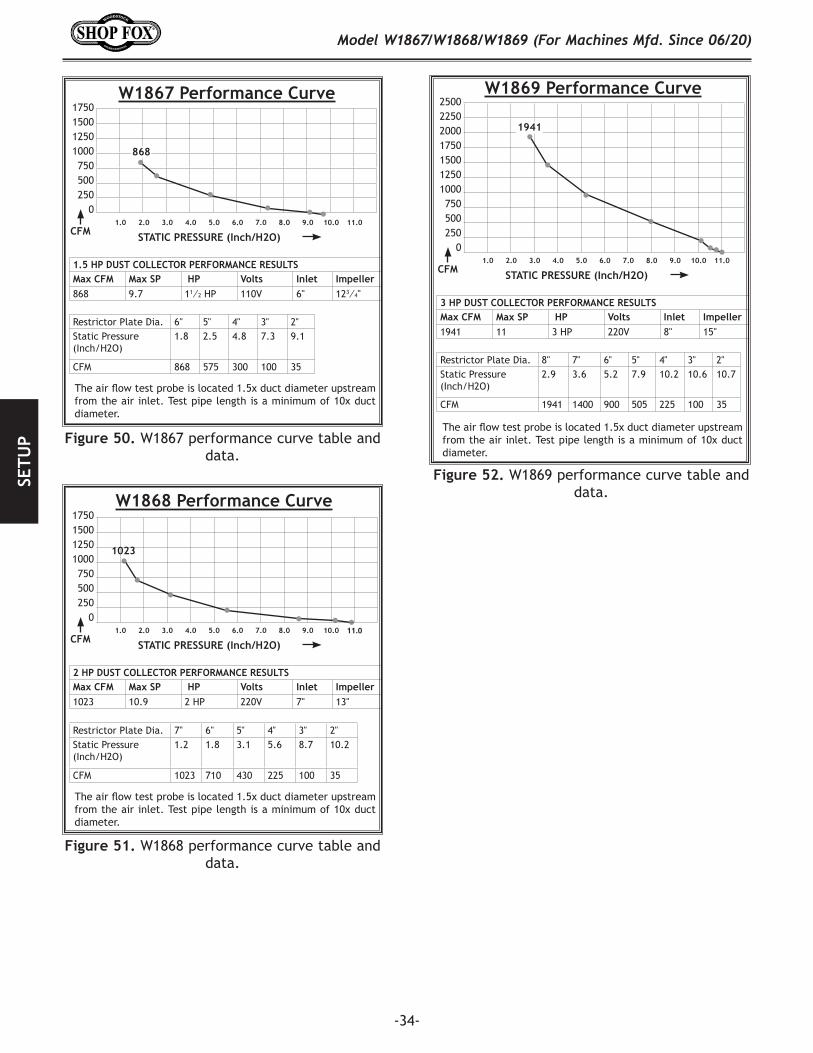
W1867 Performance Curve1750150012501000750500250
01.0 2.0 3.0 4.0 5.0 6.0 7.0 8.0 9.0 10.0 11.0
868
CFM STATIC PRESSURE (Inch/H2O)
1.5 HP DUST COLLECTOR PERFORMANCE RESULTSMax CFM Max SP HP Volts Inlet Impeller868 9.7 11⁄2 HP 110V 6" 123⁄4"
Restrictor Plate Dia. 6" 5" 4" 3" 2"Static Pressure (Inch/H2O)
1.8 2.5 4.8 7.3 9.1
CFM 868 575 300 100 35
Figure.50. W1867 performance curve table and data.
The air flow test probe is located 1.5x duct diameter upstream from the air inlet. Test pipe length is a minimum of 10x duct diameter.
W1869 Performance Curve2500225020001750150012501000750500250
01.0 2.0 3.0 4.0 5.0 6.0 7.0 8.0 9.0 10.0 11.0
1941
CFM STATIC PRESSURE (Inch/H2O)
3 HP DUST COLLECTOR PERFORMANCE RESULTSMax CFM Max SP HP Volts Inlet Impeller1941 11 3 HP 220V 8" 15"
Restrictor Plate Dia. 8" 7" 6" 5" 4" 3" 2"Static Pressure (Inch/H2O)
2.9 3.6 5.2 7.9 10.2 10.6 10.7
CFM 1941 1400 900 505 225 100 35
Figure.52. W1869 performance curve table and data.
Restrictor Plate Dia. 7" 6" 5" 4" 3" 2"Static Pressure (Inch/H2O)
1.2 1.8 3.1 5.6 8.7 10.2
CFM 1023 710 430 225 100 35
W1868 Performance Curve1750150012501000750500250
01.0 2.0 3.0 4.0 5.0 6.0 7.0 8.0 9.0 10.0 11.0
1023
CFM STATIC PRESSURE (Inch/H2O)
2 HP DUST COLLECTOR PERFORMANCE RESULTSMax CFM Max SP HP Volts Inlet Impeller1023 10.9 2 HP 220V 7" 13"
Figure.51. W1868 performance curve table and data.
The air flow test probe is located 1.5x duct diameter upstream from the air inlet. Test pipe length is a minimum of 10x duct diameter.
-35-
Model W1867/W1868/W1869 (For Machines Mfd. Since 06/20)SETU
P
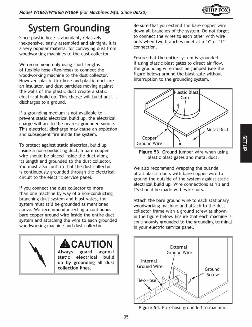
System.Grounding
External Ground Wire
Internal Ground Wire
Flex-Hose
Ground Screw
Figure.54. Flex-hose grounded to machine.
Plastic BlastGate
CopperGround Wire
Metal Duct
Figure.53. Ground jumper wire when using plastic blast gates and metal duct.
Always. guard. against.static. electrical. build.up. by. grounding. all. dust.collection.lines.
Since plastic hose is abundant, relatively inexpensive, easily assembled and air tight, it is a very popular material for conveying dust from woodworking machines to the dust collector.
We recommend only using short lengths of flexible hose (flex-hose) to connect the woodworking machine to the dust collector. However, plastic flex-hose and plastic duct are an insulator, and dust particles moving against the walls of the plastic duct create a static electrical build up. This charge will build until it discharges to a ground.
If a grounding medium is not available to prevent static electrical build up, the electrical charge will arc to the nearest grounded source. This electrical discharge may cause an explosion and subsequent fire inside the system.
To protect against static electrical build up inside a non-conducting duct, a bare copper wire should be placed inside the duct along its length and grounded to the dust collector. You must also confirm that the dust collector is continuously grounded through the electrical circuit to the electric service panel.
If you connect the dust collector to more than one machine by way of a non-conducting branching duct system and blast gates, the system must still be grounded as mentioned above. We recommend inserting a continuous bare copper ground wire inside the entire duct system and attaching the wire to each grounded woodworking machine and dust collector.
Be sure that you extend the bare copper wire down all branches of the system. Do not forget to connect the wires to each other with wire nuts when two branches meet at a "Y" or "T" connection.
Ensure that the entire system is grounded. If using plastic blast gates to direct air flow, the grounding wire must be jumped (see the figure below) around the blast gate without interruption to the grounding system.
We also recommend wrapping the outside of all plastic ducts with bare copper wire to ground the outside of the system against static electrical build up. Wire connections at Y's and T's should be made with wire nuts.
Attach the bare ground wire to each stationary woodworking machine and attach to the dust collector frame with a ground screw as shown in the figure below. Ensure that each machine is continuously grounded to the grounding terminal in your electric service panel.
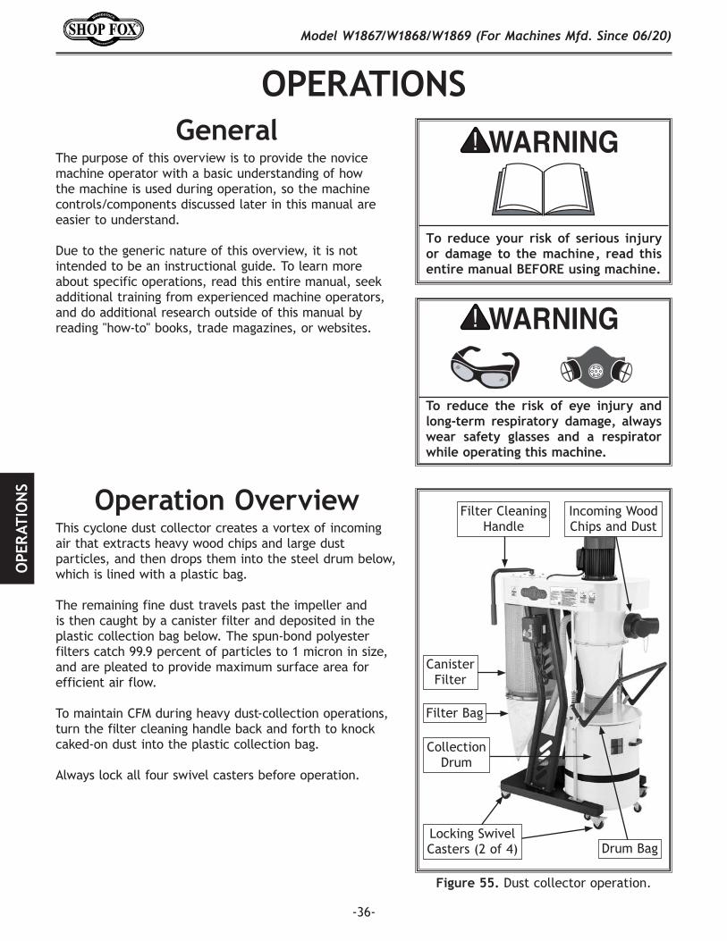
-36-
Model W1867/W1868/W1869 (For Machines Mfd. Since 06/20)O
PER
ATIO
NS
OPERATIONS
To. reduce. your. risk. of. serious. injury.or. damage. to. the. machine,. read. this.entire.manual.BEFORE.using.machine.
To. reduce. the. risk. of. eye. injury. and.long-term. respiratory. damage,. always.wear. safety. glasses. and. a. respirator.while.operating.this.machine.
GeneralThe purpose of this overview is to provide the novice machine operator with a basic understanding of how the machine is used during operation, so the machine controls/components discussed later in this manual are easier to understand.
Due to the generic nature of this overview, it is not intended to be an instructional guide. To learn more about specific operations, read this entire manual, seek additional training from experienced machine operators, and do additional research outside of this manual by reading "how-to" books, trade magazines, or websites.
Operation.OverviewThis cyclone dust collector creates a vortex of incoming air that extracts heavy wood chips and large dust particles, and then drops them into the steel drum below, which is lined with a plastic bag.
The remaining fine dust travels past the impeller and is then caught by a canister filter and deposited in the plastic collection bag below. The spun-bond polyester filters catch 99.9 percent of particles to 1 micron in size, and are pleated to provide maximum surface area for efficient air flow.
To maintain CFM during heavy dust-collection operations, turn the filter cleaning handle back and forth to knock caked-on dust into the plastic collection bag.
Always lock all four swivel casters before operation.
Figure.55..Dust collector operation.
Incoming Wood Chips and Dust
Locking Swivel Casters (2 of 4)
Filter Cleaning Handle
Canister Filter
Filter Bag
Collection Drum
Drum Bag
-37-
Model W1867/W1868/W1869 (For Machines Mfd. Since 06/20)O
PERATIO
NS
Programming.ReceiverThe Models W1867-69 are equipped with a remote control receiver that can be programmed to operate up to 16 separate controllers.
To.program.receiver,.do.these.steps:
1. Remove switch cover to get a clear view of remote receiver (see Figure 56).
2. Press and hold green ON button on remote control until LED indicator illuminates on remote receiver (see Figure.57).
3. Press button shown in Figure 57, then release when LED indicator turns off. Pairing is complete.
4. To erase all current transmitter codes, press green ON button on remote control for eight seconds, then wait for LED indicator to flash three times. Repeat Steps.2–3 to program receiver to accept new remote controller(s).
Figure.56. Location of remote receiver (W1869 shown).
Contactor
RemoteReceiver
Figure.57. Remote receiver features.
LEDIndicator
Button
Avoid.touching.electrified.parts.inside.receiver.while.performing.procedure.below!.Touching.electrified.parts.will.result.in.personal.injury.but.not.limited.to.severe.burns,.electrocution,.or.death..Use.a.wood.dowel.or.other.non-conducting.item.to.push.button.on.receiver.
-38-
Model W1867/W1868/W1869 (For Machines Mfd. Since 06/20)O
PER
ATIO
NS
ACCESSORIESCyclone.Dust.Collector.Accessories
The following cyclone dust collector accessories may be available through your local Woodstock International Inc. Dealer. If you do not have a dealer in your area, these products are also available through online dealers. Please call or e-mail Woodstock International Inc. Customer Service to get a current listing of dealers at: 1-800-840-8420 or at [email protected].
D4206—Clear.Flexible.Hose.4".x.10'D4256—45°.Elbow.4"W1007—Plastic.Blast.Gate.4"W1017—90°.Elbow.4"D4216—Black.Flexible.Hose.4".x.10'W1053—Anti-Static.Grounding.KitW1317—Wire.Hose.Clamp.4"We've handpicked a selection of commonly used dust-collection components for machines with 4" dust ports.
D4026
W1317
D4256 W1007
D4216
W1053
W1017
W1014—3".Outer.Diameter.Y-FittingsW1015—4".Outer.Diameter.Y-FittingsUsed to attach branch lines to service more than one machine. This design provides increased lateral air flow and efficiency over other types of fittings.
W1050—Dust.Collection.Basics.BookThis incisive book skillfully guides the woodworker through all the steps necessary in the design and construction of an efficient central dust-collection system and tells you what you need to know for easy installation. 64 pages.
Accessories
-39-
Model W1867/W1868/W1869 (For Machines Mfd. Since 06/20)O
PERATIO
NS
W1053—Grounding.KitProvides everything you need to ground a dust collection system, including directions for installation. A large system may need more than one kit, so keep plenty of these on hand. This safety accessory is essential to any complete dust collection assortment.
W1055—Dust.Collection.Accessories.Kit.#2Provides the necessary hoses, clamps, hoods and fittings to connect two woodworking machines to a dust collector. Air flow to each machine is controlled by a blast gate. Kit comes complete with comprehensive instructions and can be expanded even further using our other dust collection accessories (list enclosed in each box).
Kit includes: • (2) 4" Blast gates (W1007)• (2) 4" x 10' Hose (W1031)• (1) Table saw dust hood (W1004)• (1) Universal dust hood (W1010)• (1) 4" Y-fitting (W1015)• (10) 4" Wire hose clamps (W1317)• Shipping weight: 15 lbs. 14 oz.• Package size: 24" x 24" x 12"
W1039—Universal.AdapterThis adapter provides a multitude of reducing options. Simply cut off unneeded steps. Outside diameter sizes include 1", 2", 2.5", 3", 4", 5", and 6". Wall thickness is 1⁄8".
Blast.GatesAvailable in both black ABS plastic and aluminum. Plastic blast gates are economically priced, have a textured surface and an easy sliding gate action. For those customers who prefer metal, our top quality aluminum blast gates feature a cast aluminum body with steel gate and locking knob. The following types and models are available:
Black ABS plastic blast gates:W1006 3" Outer DiameterW1007 4" Outer DiameterW1008 5" Outer DiameterW1009 6" Outer Diameter
Aluminum blast gates:W1141 3" Outer DiameterW1142 4" Outer Diameter
W1141W1006
-40-
Model W1867/W1868/W1869 (For Machines Mfd. Since 06/20)M
AIN
TEN
AN
CE
MAINTENANCE
For optimum performance from this machine, this maintenance schedule must be strictly followed.
OngoingTo maintain a low risk of injury and proper machine operation, if you ever observe any of the items below, shut down the machine immediately and fix the problem before continuing operations:
• Loose mounting bolts.• Damaged filter canister, cleaning paddle
components, or collection bags.• Worn or damaged wires.• Suction leaks.• Any other unsafe condition.
Monthly.Check• Clean/vacuum dust buildup off machine body and
motor.
General
IMPORTANT: To contain wood dust and minimize risk of exposure, firmly tie bag closed.
If the bag gets overfilled, the dust will be sucked into the intake barrel and passed through to the canister filter and filter bag. Avoid allowing this to happen, as it may reduce filter life.
Check the drum window regularly to prevent excessive dust buildup in the collection drum.
Emptying/Replacing.Collection.Drum.Bag
Dispose of the collection drum bag when dust fills it 3⁄4 full. Replace the bag if it develops a leak or becomes damaged.
Dust. exposure. created. while. using.machinery. may. cause. cancer,. birth.defects,. or. long-term. respiratory.damage.. Always. wear. goggles. and. a.NIOSH-approved. respirator. when.working. with. the. dust. collection. bags.or.canisters.
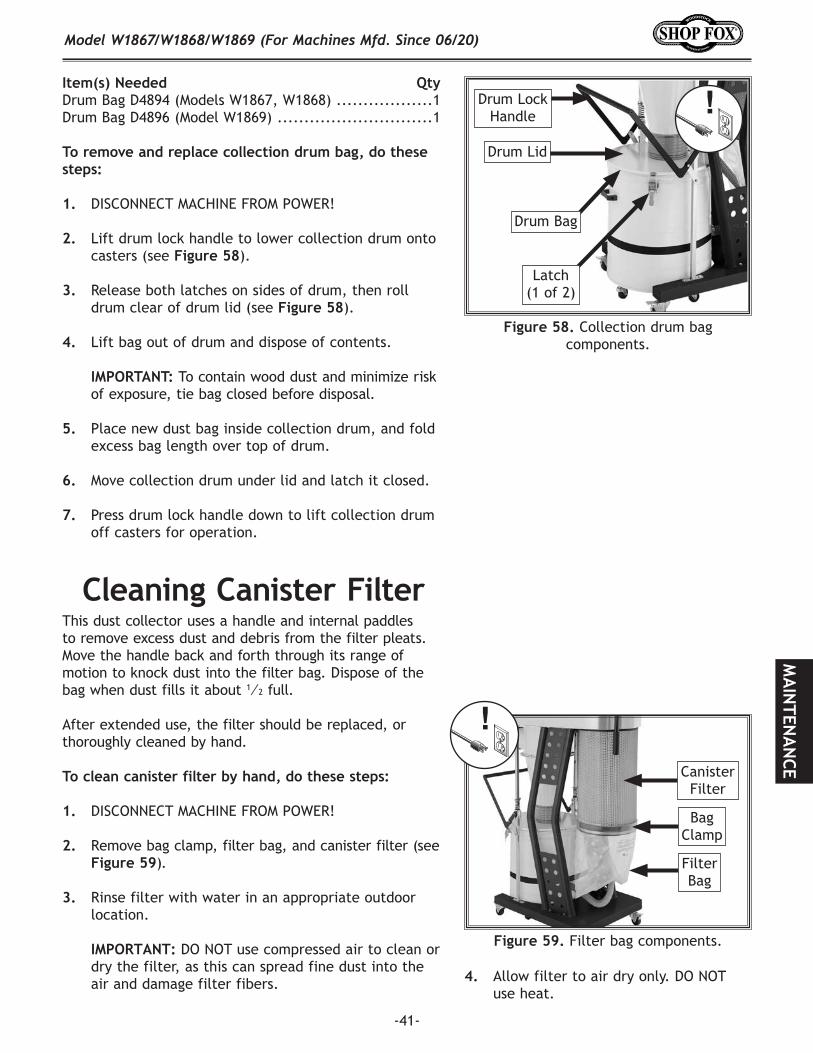
-41-
Model W1867/W1868/W1869 (For Machines Mfd. Since 06/20)M
AIN
TENA
NCE
Cleaning.Canister.FilterThis dust collector uses a handle and internal paddles to remove excess dust and debris from the filter pleats. Move the handle back and forth through its range of motion to knock dust into the filter bag. Dispose of the bag when dust fills it about 1⁄2 full.
After extended use, the filter should be replaced, or thoroughly cleaned by hand.
To.clean.canister.filter.by.hand,.do.these.steps:
1. DISCONNECT MACHINE FROM POWER!
2. Remove bag clamp, filter bag, and canister filter (see Figure.59).
3. Rinse filter with water in an appropriate outdoor location.
IMPORTANT:.DO NOT use compressed air to clean or dry the filter, as this can spread fine dust into the air and damage filter fibers.
Item(s).Needed. QtyDrum Bag D4894 (Models W1867, W1868) ..................1Drum Bag D4896 (Model W1869) .............................1
To.remove.and.replace.collection.drum.bag,.do.these.steps:
1. DISCONNECT MACHINE FROM POWER!
2. Lift drum lock handle to lower collection drum onto casters (see Figure.58).
3. Release both latches on sides of drum, then roll drum clear of drum lid (see Figure.58).
4. Lift bag out of drum and dispose of contents.
IMPORTANT: To contain wood dust and minimize risk of exposure, tie bag closed before disposal.
5. Place new dust bag inside collection drum, and fold excess bag length over top of drum.
6. Move collection drum under lid and latch it closed.
7. Press drum lock handle down to lift collection drum off casters for operation.
Figure.58. Collection drum bag components.
Drum Lid
Drum Lock Handle
Drum Bag
Latch (1 of 2)
Figure.59. Filter bag components.
Canister Filter
Bag Clamp
Filter Bag
4. Allow filter to air dry only. DO NOT use heat.
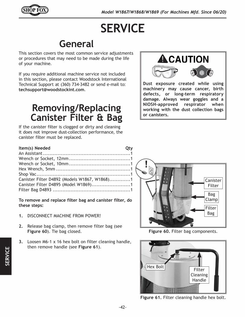
-42-
Model W1867/W1868/W1869 (For Machines Mfd. Since 06/20)SE
RVIC
E
SERVICEGeneral
This section covers the most common service adjustments or procedures that may need to be made during the life of your machine.
If you require additional machine service not included in this section, please contact Woodstock International Technical Support at (360) 734-3482 or send e-mail to: [email protected].
Removing/Replacing.Canister.Filter.&.Bag
Item(s).Needed. QtyAn Assistant ......................................................1Wrench or Socket, 12mm ......................................1Wrench or Socket, 10mm ......................................1Hex Wrench, 5mm ..............................................1Shop Vac ..........................................................1Canister Filter D4892 (Models W1867, W1868) .............1Canister Filter D4895 (Model W1869) ........................1Filter Bag D4893 ................................................1
To.remove.and.replace.filter.bag.and.canister.filter,.do.these.steps:
1. DISCONNECT MACHINE FROM POWER!
2. Release bag clamp, then remove filter bag (see Figure.60). Tie bag closed.
If the canister filter is clogged or dirty and cleaning it does not improve dust-collection performance, the canister filter must be replaced.
Figure.60. Filter bag components.
Canister Filter
Bag Clamp
Filter Bag
Dust. exposure. created. while. using.machinery. may. cause. cancer,. birth.defects,. or. long-term. respiratory.damage.. Always. wear. goggles. and. a.NIOSH-approved. respirator. when.working. with. the. dust. collection. bags.or.canisters.
Figure.61. Filter cleaning handle hex bolt.
Filter Cleaning Handle
Hex Bolt
3. Loosen M6-1 x 16 hex bolt on filter cleaning handle, then remove handle (see Figure.61).
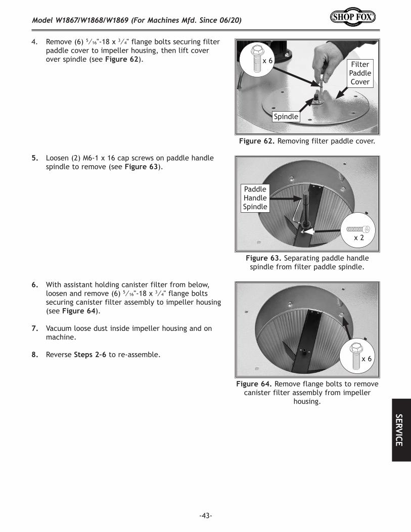
-43-
Model W1867/W1868/W1869 (For Machines Mfd. Since 06/20)SERVICE
5. Loosen (2) M6-1 x 16 cap screws on paddle handle spindle to remove (see Figure.63).
4. Remove (6) 5⁄16"-18 x 3⁄4" flange bolts securing filter paddle cover to impeller housing, then lift cover over spindle (see Figure.62).
Figure.63. Separating paddle handle spindle from filter paddle spindle.
6. With assistant holding canister filter from below, loosen and remove (6) 5⁄16"-18 x 3⁄4" flange bolts securing canister filter assembly to impeller housing (see Figure.64).
7. Vacuum loose dust inside impeller housing and on machine.
8. Reverse Steps.2–6 to re-assemble.
Figure.64. Remove flange bolts to remove canister filter assembly from impeller
housing.
x 6
Figure.62. Removing filter paddle cover.
x 6
Spindle
Filter Paddle Cover
Paddle Handle Spindle
x 2
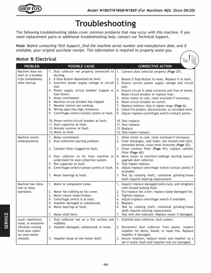
-44-
Model W1867/W1868/W1869 (For Machines Mfd. Since 06/20)SE
RVIC
E
Troubleshooting
Motor.&.Electrical
The following troubleshooting tables cover common problems that may occur with this machine. If you need replacement parts or additional troubleshooting help, contact our Technical Support.
Note: Before contacting Tech Support, find the machine serial number and manufacture date, and if available, your original purchase receipt. This information is required to properly assist you.
PROBLEM POSSIBLE.CAUSE CORRECTIVE.ACTIONMachine does not start or a breaker trips immediately after startup.
1. Dust collector not properly connected to ducting.
2. E-Stop Button depressed/at fault.3. Incorrect power supply voltage or circuit
size.4. Power supply circuit breaker tripped or
fuse blown. 5. Motor overheated.6. Machine circuit breaker has tripped.7. Remote control not working.8. Wiring open/has high resistance.9. Centrifugal switch/contact points at fault.
10. Power switch/circuit breaker at fault. 11. Start capacitor at fault.12. Remote receiver at fault.13. Motor at fault.
1. Connect dust collector properly (Page.27).
2. Rotate E-Stop Button to reset. Replace if at fault.3. Ensure correct power supply voltage and circuit
size.4. Ensure circuit is sized correctly and free of shorts.
Reset circuit breaker or replace fuse.5. Allow motor to cool, reset overload if necessary.6. Reset circuit breaker on switch.7. Replace battery; stay in signal range (Page.6).8. Check/fix broken, disconnected, or corroded wires.9. Adjust/replace centrifugal switch/contact points.
10. Test/replace.11. Test/replace.12. Replace.13. Test/repair/replace.
Machine seems underpowered.
1. Motor overheated.2. Dust-collection ducting problem.
3. Canister filter clogged/at fault.
4. Dust collector to far from machine or undersized for dust-collection system.
5. Run capacitor at fault.6. Centrifugal switch/contact points at fault.
7. Motor bearings at fault.
1. Allow motor to cool, reset overload if necessary.2. Clear blockages, seal leaks, use smooth-wall duct,
eliminate bends, close other branches (Page.27).3. Clean canister filter (Page. 41); replace canister
filter (Page.42).4. Move closer to machine/redesign ducting layout/
upgrade dust collector.5. Test/repair/replace.6. Adjust/replace centrifugal switch/contact points if
available.7. Test by rotating shaft; rotational grinding/loose
shaft requires bearing replacement.
Machine has vibra-tion or noisy operation.
1. Motor or component loose.
2. Motor fan rubbing on fan cover.3. Motor mount loose/broken.4. Centrifugal switch is at fault.5. Impeller damaged or unbalanced.6. Motor bearings at fault.
7. Motor shaft bent.
1. Inspect/replace damaged bolts/nuts, and retighten with thread-locking fluid.
2. Fix/replace fan cover; replace loose/damaged fan.3. Tighten/replace.4. Adjust/replace centrifugal switch if available.5. Replace.6. Test by rotating shaft; rotational grinding/loose
shaft requires bearing replacement.7. Test with dial indicator. Replace motor if damaged.
Loud, repetitious noise, or excessive vibration coming from dust collec-tor (non-motor related).
1. Dust collector not on a flat surface and wobbles.
2. Impeller damaged, unbalanced, or loose.
3. Impeller loose on the motor shaft.
1. Stabilize dust collector; lock casters.
2. Disconnect dust collector from power. Inspect impeller for dents, bends, or loose fins. Replace impeller if damaged.
3. Secure impeller; replace motor and impeller as a set if motor shaft and impeller hub are damaged.
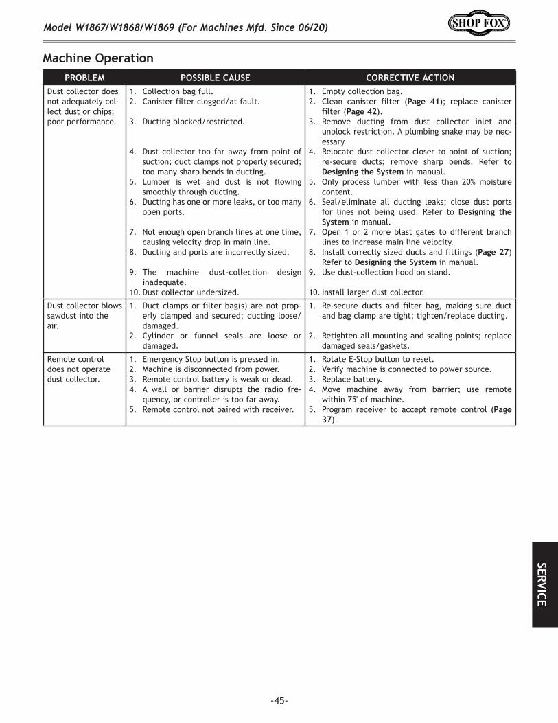
-45-
Model W1867/W1868/W1869 (For Machines Mfd. Since 06/20)SERVICE
Machine.OperationPROBLEM POSSIBLE.CAUSE CORRECTIVE.ACTION
Dust collector does not adequately col-lect dust or chips; poor performance.
1. Collection bag full.2. Canister filter clogged/at fault.
3. Ducting blocked/restricted.
4. Dust collector too far away from point ofsuction; duct clamps not properly secured;too many sharp bends in ducting.
5. Lumber is wet and dust is not flowingsmoothly through ducting.
6. Ducting has one or more leaks, or too manyopen ports.
7. Not enough open branch lines at one time,causing velocity drop in main line.
8. Ducting and ports are incorrectly sized.
9. The machine dust-collection designinadequate.
10. Dust collector undersized.
1. Empty collection bag.2. Clean canister filter (Page. 41); replace canister
filter (Page.42).3. Remove ducting from dust collector inlet and
unblock restriction. A plumbing snake may be nec-essary.
4. Relocate dust collector closer to point of suction;re-secure ducts; remove sharp bends. Refer toDesigning.the.System in manual.
5. Only process lumber with less than 20% moisturecontent.
6. Seal/eliminate all ducting leaks; close dust portsfor lines not being used. Refer to Designing. theSystem in manual.
7. Open 1 or 2 more blast gates to different branchlines to increase main line velocity.
8. Install correctly sized ducts and fittings (Page.27)Refer to Designing.the.System in manual.
9. Use dust-collection hood on stand.
10. Install larger dust collector.
Dust collector blows sawdust into the air.
1. Duct clamps or filter bag(s) are not prop-erly clamped and secured; ducting loose/damaged.
2. Cylinder or funnel seals are loose ordamaged.
1. Re-secure ducts and filter bag, making sure ductand bag clamp are tight; tighten/replace ducting.
2. Retighten all mounting and sealing points; replacedamaged seals/gaskets.
Remote control does not operate dust collector.
1. Emergency Stop button is pressed in.2. Machine is disconnected from power.3. Remote control battery is weak or dead.4. A wall or barrier disrupts the radio fre-
quency, or controller is too far away.5. Remote control not paired with receiver.
1. Rotate E-Stop button to reset.2. Verify machine is connected to power source.3. Replace battery.4. Move machine away from barrier; use remote
within 75' of machine.5. Program receiver to accept remote control (Page
37).
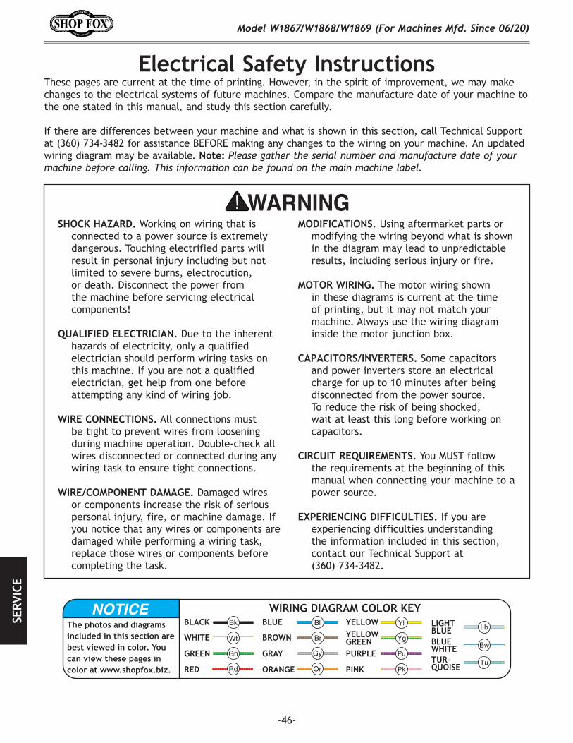
-46-
Model W1867/W1868/W1869 (For Machines Mfd. Since 06/20)SE
RVIC
E
Electrical.Safety.Instructions
SHOCK.HAZARD. Working on wiring that is connected to a power source is extremely dangerous. Touching electrified parts will result in personal injury including but not limited to severe burns, electrocution, or death. Disconnect the power from the machine before servicing electrical components!
QUALIFIED.ELECTRICIAN. Due to the inherent hazards of electricity, only a qualified electrician should perform wiring tasks on this machine. If you are not a qualified electrician, get help from one before attempting any kind of wiring job.
WIRE.CONNECTIONS. All connections must be tight to prevent wires from loosening during machine operation. Double-check all wires disconnected or connected during any wiring task to ensure tight connections.
WIRE/COMPONENT.DAMAGE..Damaged wires or components increase the risk of serious personal injury, fire, or machine damage. If you notice that any wires or components are damaged while performing a wiring task, replace those wires or components before completing the task.
MODIFICATIONS. Using aftermarket parts or modifying the wiring beyond what is shown in the diagram may lead to unpredictable results, including serious injury or fire.
MOTOR.WIRING. The motor wiring shown in these diagrams is current at the time of printing, but it may not match your machine. Always use the wiring diagram inside the motor junction box.
CAPACITORS/INVERTERS. Some capacitors and power inverters store an electrical charge for up to 10 minutes after being disconnected from the power source. To reduce the risk of being shocked, wait at least this long before working on capacitors.
CIRCUIT.REQUIREMENTS. You MUST follow the requirements at the beginning of this manual when connecting your machine to a power source.
EXPERIENCING.DIFFICULTIES. If you are experiencing difficulties understanding the information included in this section, contact our Technical Support at
(360) 734-3482.
The photos and diagrams included in this section are best viewed in color. You can view these pages in color at www.shopfox.biz.
BLACK
WHITE
GREEN
RED
BLUE
BROWN
GRAY
ORANGE
YELLOWYELLOWGREENPURPLE
PINK
LIGHTBLUEBLUEWHITETUR-QUOISE
WIRING DIAGRAM COLOR KEY
These pages are current at the time of printing. However, in the spirit of improvement, we may make changes to the electrical systems of future machines. Compare the manufacture date of your machine to the one stated in this manual, and study this section carefully.
If there are differences between your machine and what is shown in this section, call Technical Support at (360) 734-3482 for assistance BEFORE making any changes to the wiring on your machine. An updated wiring diagram may be available. Note: Please gather the serial number and manufacture date of your machine before calling. This information can be found on the main machine label.
electrical.warning.page

-47-
Model W1867/W1868/W1869 (For Machines Mfd. Since 06/20)SERVICE
Electrical.Components
Figure.68. Magnetic switch.
Figure.67. Contactor and remote control receiver location (W1869 shown). Figure.70. Remote control unit.
Figure.69. Emergency-stop switch and contact block.
Figure.66. Circuit breaker.
Emergency Stop Switch
Contact Block
ON Button
OFF Button
Emergency Stop Button
ON Button
Figure.65. Junction box components (W1867 shown).
Start Capacitor
Run Capacitor
Circuit Breaker
Circuit Breaker
Contactor
Remote Control Receiver
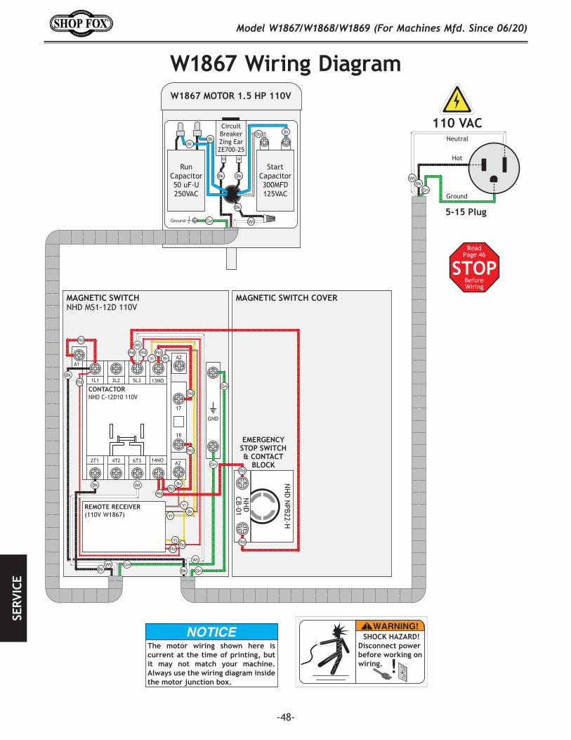
-48-
Model W1867/W1868/W1869 (For Machines Mfd. Since 06/20)SE
RVIC
E
STOPRead
Page 46
Before Wiring
W1867.Wiring.Diagram
Neutral
Hot
Ground
110 VAC
5-15 Plug
A1
A2
REMOTE RECEIVER(110V W1867)
GND
A2
2T1 6T3 14NO4T2
1L1 5L3 13NO3L2
CONTACTORNHD C-12D10 110V
EMERGENCYSTOP SWITCH& CONTACT
BLOCK
17
18
Ground
RunCapacitor50 uF-U250VAC
W1867 MOTOR 1.5 HP 110V
CircuitBreakerZing EarZE700-25
StartCapacitor300MFD125VAC
MAGNETIC SWITCHNHD MS1-12D 110V
MAGNETIC SWITCH COVER
NH
D
CB-01
NH
D N
PB22-H
The motor wiring shown here is current at the time of printing, but it may not match your machine. Always use the wiring diagram inside the motor junction box.
SHOCK HAZARD!Disconnect power before working on wiring.
wiring
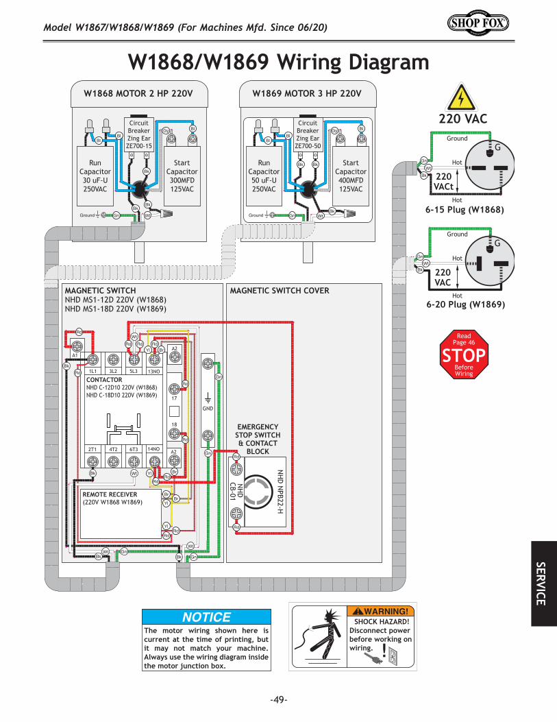
-49-
Model W1867/W1868/W1869 (For Machines Mfd. Since 06/20)SERVICE
STOPRead
Page 46
Before Wiring
W1868/W1869.Wiring.Diagram
Hot
Hot
Ground
6-15 Plug (W1868)
220VACt
G
Hot
Hot
Ground
6-20 Plug (W1869)
220VAC
G
220 VAC
A1
A2
REMOTE RECEIVER(220V W1868 W1869)
GND
A2
2T1 6T3 14NO4T2
1L1 5L3 13NO3L2
CONTACTORNHD C-12D10 220V (W1868)NHD C-18D10 220V (W1869)
EMERGENCYSTOP SWITCH& CONTACT
BLOCK
17
18
Ground
RunCapacitor30 uF-U250VAC
W1868 MOTOR 2 HP 220V
CircuitBreakerZing EarZE700-15
StartCapacitor300MFD125VAC
Ground
RunCapacitor50 uF-U250VAC
W1869 MOTOR 3 HP 220V
CircuitBreakerZing EarZE700-50
StartCapacitor400MFD125VAC
MAGNETIC SWITCHNHD MS1-12D 220V (W1868)NHD MS1-18D 220V (W1869)
MAGNETIC SWITCH COVER
NH
D
CB-01
NH
D N
PB22-H
The motor wiring shown here is current at the time of printing, but it may not match your machine. Always use the wiring diagram inside the motor junction box.
SHOCK HAZARD!Disconnect power before working on wiring.
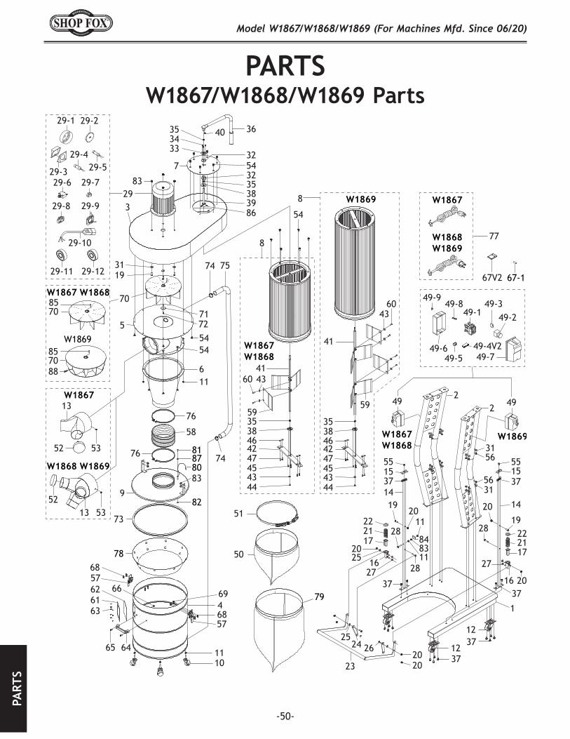
-50-
Model W1867/W1868/W1869 (For Machines Mfd. Since 06/20)PA
RTS
PARTSW1867/W1868/W1869.Parts
67V2
77
3640353433
3254732353839
83293
3119
49 492
3156
2
5515
142019
27
28
37
222117
16
1
1237
75
74
6857
11
4
10
65 64
636162
6857
66 69
73
9
76
58
76
11
28
84
37
14
6
2019
1537
55
37
222117
16
70
57172
74
5454
2025
2811
11
83
3712
3156
86
78
81
8087
82
29-2
29-3
29-1
29-429-5
29-6 29-7
29-8 29-9
29-10
49-149-8
49-4V249-5
54
41
59
4360
3538464247454344
51
50
3538464247454344
2020
20
23
2524 26
83
27
W1867
W1869
W1869
W1869W1867W1868
W1867W1868
W1867 W1868
W1868 W1869
W1867
W1868W1869
52
52
13
13
53
53
7085
49-7
49-349-2
49-6
49-9
67-129-11 29-12
6043
59
41
7085
88
8
8
79
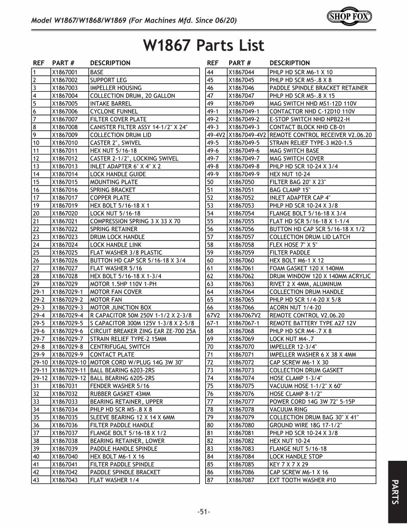
-51-
Model W1867/W1868/W1869 (For Machines Mfd. Since 06/20)PA
RTS
W1867.Parts.ListREF PART # DESCRIPTION REF PART # DESCRIPTION1 X1867001 BASE 44 X1867044 PHLP HD SCR M6-1 X 102 X1867002 SUPPORT LEG 45 X1867045 PHLP HD SCR M5-.8 X 83 X1867003 IMPELLER HOUSING 46 X1867046 PADDLE SPINDLE BRACKET RETAINER4 X1867004 COLLECTION DRUM, 20 GALLON 47 X1867047 PHLP HD SCR M5-.8 X 155 X1867005 INTAKE BARREL 49 X1867049 MAG SWITCH NHD MS1-12D 110V6 X1867006 CYCLONE FUNNEL 49-1 X1867049-1 CONTACTOR NHD C-12D10 110V7 X1867007 FILTER COVER PLATE 49-2 X1867049-2 E-STOP SWITCH NHD NPB22-H8 X1867008 CANISTER FILTER ASSY 14-1/2" X 24" 49-3 X1867049-3 CONTACT BLOCK NHD CB-019 X1867009 COLLECTION DRUM LID 49-4V2 X1867049-4V2 REMOTE CONTROL RECEIVER V2.06.2010 X1867010 CASTER 2", SWIVEL 49-5 X1867049-5 STRAIN RELIEF TYPE-3 M20-1.511 X1867011 HEX NUT 5/16-18 49-6 X1867049-6 MAG SWITCH BASE12 X1867012 CASTER 2-1/2", LOCKING SWIVEL 49-7 X1867049-7 MAG SWITCH COVER13 X1867013 INLET ADAPTER 6" X 4" X 2 49-8 X1867049-8 PHLP HD SCR 10-24 X 3/414 X1867014 LOCK HANDLE GUIDE 49-9 X1867049-9 HEX NUT 10-2415 X1867015 MOUNTING PLATE 50 X1867050 FILTER BAG 20" X 23"16 X1867016 SPRING BRACKET 51 X1867051 BAG CLAMP 15"17 X1867017 COPPER PLATE 52 X1867052 INLET ADAPTER CAP 4"19 X1867019 HEX BOLT 5/16-18 X 1 53 X1867053 PHLP HD SCR 10-24 X 3/820 X1867020 LOCK NUT 5/16-18 54 X1867054 FLANGE BOLT 5/16-18 X 3/421 X1867021 COMPRESSION SPRING 3 X 33 X 70 55 X1867055 FLAT HD SCR 5/16-18 X 1-1/422 X1867022 SPRING RETAINER 56 X1867056 BUTTON HD CAP SCR 5/16-18 X 1/223 X1867023 DRUM LOCK HANDLE 57 X1867057 COLLECTION DRUM LID LATCH 24 X1867024 LOCK HANDLE LINK 58 X1867058 FLEX HOSE 7" X 5"25 X1867025 FLAT WASHER 3/8 PLASTIC 59 X1867059 FILTER PADDLE 26 X1867026 BUTTON HD CAP SCR 5/16-18 X 3/4 60 X1867060 HEX BOLT M6-1 X 1227 X1867027 FLAT WASHER 5/16 61 X1867061 FOAM GASKET 120 X 140MM28 X1867028 HEX BOLT 5/16-18 X 1-3/4 62 X1867062 DRUM WINDOW 120 X 140MM ACRYLIC29 X1867029 MOTOR 1.5HP 110V 1-PH 63 X1867063 RIVET 2 X 4MM, ALUMINUM29-1 X1867029-1 MOTOR FAN COVER 64 X1867064 COLLECTION DRUM HANDLE29-2 X1867029-2 MOTOR FAN 65 X1867065 PHLP HD SCR 1/4-20 X 5/829-3 X1867029-3 MOTOR JUNCTION BOX 66 X1867066 ACORN NUT 1/4-2029-4 X1867029-4 R CAPACITOR 50M 250V 1-1/2 X 2-3/8 67V2 X1867067V2 REMOTE CONTROL V2.06.2029-5 X1867029-5 S CAPACITOR 300M 125V 1-3/8 X 2-5/8 67-1 X1867067-1 REMOTE BATTERY TYPE A27 12V29-6 X1867029-6 CIRCUIT BREAKER ZING EAR ZE-700 25A 68 X1867068 PHLP HD SCR M4-.7 X 829-7 X1867029-7 STRAIN RELIEF TYPE-2 15MM 69 X1867069 LOCK NUT M4-.729-8 X1867029-8 CENTRIFUGAL SWITCH 70 X1867070 IMPELLER 12-3/4"29-9 X1867029-9 CONTACT PLATE 71 X1867071 IMPELLER WASHER 6 X 38 X 4MM29-10 X1867029-10 MOTOR CORD W/PLUG 14G 3W 30" 72 X1867072 CAP SCREW M6-1 X 3029-11 X1867029-11 BALL BEARING 6203-2RS 73 X1867073 COLLECTION DRUM GASKET29-12 X1867029-12 BALL BEARING 6205-2RS 74 X1867074 HOSE CLAMP 1-3/4"31 X1867031 FENDER WASHER 5/16 75 X1867075 VACUUM HOSE 1-1/2" X 60"32 X1867032 RUBBER GASKET 43MM 76 X1867076 HOSE CLAMP 8-1/2"33 X1867033 BEARING RETAINER, UPPER 77 X1867077 POWER CORD 14G 3W 72" 5-15P34 X1867034 PHLP HD SCR M5-.8 X 8 78 X1867078 VACUUM RING35 X1867035 SLEEVE BEARING 12 X 14 X 6MM 79 X1867079 COLLECTION DRUM BAG 30" X 41"36 X1867036 FILTER PADDLE HANDLE 80 X1867080 GROUND WIRE 18G 17-1/2"37 X1867037 FLANGE BOLT 5/16-18 X 1/2 81 X1867081 PHLP HD SCR 10-24 X 3/838 X1867038 BEARING RETAINER, LOWER 82 X1867082 HEX NUT 10-2439 X1867039 PADDLE HANDLE SPINDLE 83 X1867083 FLANGE NUT 5/16-1840 X1867040 HEX BOLT M6-1 X 16 84 X1867084 LOCK HANDLE STOP41 X1867041 FILTER PADDLE SPINDLE 85 X1867085 KEY 7 X 7 X 2942 X1867042 PADDLE SPINDLE BRACKET 86 X1867086 CAP SCREW M6-1 X 1643 X1867043 FLAT WASHER 1/4 87 X1867087 EXT TOOTH WASHER #10

-52-
Model W1867/W1868/W1869 (For Machines Mfd. Since 06/20)PA
RTS
W1868.Parts.ListREF PART # DESCRIPTION REF PART # DESCRIPTION1 X1868001 BASE 44 X1868044 PHLP HD SCR M6-1 X 102 X1868002 SUPPORT LEG 45 X1868045 PHLP HD SCR M5-.8 X 83 X1868003 IMPELLER HOUSING 46 X1868046 PADDLE SPINDLE BRACKET RETAINER4 X1868004 COLLECTION DRUM, 20 GALLON 47 X1868047 PHLP HD SCR M5-.8 X 155 X1868005 INTAKE BARREL 49 X1868049 MAG SWITCH NHD MS1-12D 220V6 X1868006 CYCLONE FUNNEL 49-1 X1868049-1 CONTACTOR NHD C-12D10 220V7 X1868007 FILTER COVER PLATE 49-2 X1868049-2 E-STOP SWITCH NHD NPB22-H8 X1868008 CANISTER FILTER ASSY 14-1/2" X 24" 49-3 X1868049-3 CONTACT BLOCK NHD CB-019 X1868009 COLLECTION DRUM LID 49-4V2 X1868049-4V2 REMOTE CONTROL RECEIVER V2.06.2010 X1868010 CASTER 2", SWIVEL 49-5 X1868049-5 STRAIN RELIEF TYPE-3 M20-1.511 X1868011 HEX NUT 5/16-18 49-6 X1868049-6 MAG SWITCH BASE12 X1868012 CASTER 2-1/2", LOCKING SWIVEL 49-7 X1868049-7 MAG SWITCH COVER13 X1868013 INLET ADAPTER 7" X 4" X 3 49-8 X1868049-8 PHLP HD SCR 10-24 X 3/414 X1868014 LOCK HANDLE GUIDE 49-9 X1868049-9 HEX NUT 10-2415 X1868015 MOUNTING PLATE 50 X1868050 FILTER BAG 20" X 23"16 X1868016 SPRING BRACKET 51 X1868051 BAG CLAMP 15"17 X1868017 COPPER PLATE 52 X1868052 INLET ADAPTER CAP 4"19 X1868019 HEX BOLT 5/16-18 X 1 53 X1868053 PHLP HD SCR 10-24 X 3/820 X1868020 LOCK NUT 5/16-18 54 X1868054 FLANGE BOLT 5/16-18 X 3/421 X1868021 COMPRESSION SPRING 3 X 33 X 70 55 X1868055 FLAT HD SCR 5/16-18 X 1-1/422 X1868022 SPRING RETAINER 56 X1868056 BUTTON HD CAP SCR 5/16-18 X 1/223 X1868023 DRUM LOCK HANDLE 57 X1868057 COLLECTION DRUM LID LATCH 24 X1868024 LOCK HANDLE LINK 58 X1868058 FLEX HOSE 8" X 7"25 X1868025 FLAT WASHER 3/8 PLASTIC 59 X1868059 FILTER PADDLE 26 X1868026 BUTTON HD CAP SCR 5/16-18 X 3/4 60 X1868060 HEX BOLT M6-1 X 1227 X1868027 FLAT WASHER 5/16 61 X1868061 FOAM GASKET 120 X 140MM28 X1868028 HEX BOLT 5/16-18 X 1-3/4 62 X1868062 DRUM WINDOW 120 X 140MM ACRYLIC29 X1868029 MOTOR 2HP 220V 1-PH 63 X1868063 RIVET 2 X 4MM, ALUMINUM29-1 X1868029-1 MOTOR FAN COVER 64 X1868064 COLLECTION DRUM HANDLE29-2 X1868029-2 MOTOR FAN 65 X1868065 PHLP HD SCR 1/4-20 X 5/829-3 X1868029-3 MOTOR JUNCTION BOX 66 X1868066 ACORN NUT 1/4-2029-4 X1868029-4 R CAPACITOR 30M 250V 1-1/2 X 2-3/8 67V2 X1868067V2 REMOTE CONTROL V2.06.2029-5 X1868029-5 S CAPACITOR 300M 125V 1-3/8 X 2-5/8 67-1 X1868067-1 REMOTE BATTERY TYPE A27 12V29-6 X1868029-6 CIRCUIT BREAKER ZING EAR ZE-700 15A 68 X1868068 PHLP HD SCR M4-.7 X 829-7 X1868029-7 STRAIN RELIEF TYPE-2 15MM 69 X1868069 LOCK NUT M4-.729-8 X1868029-8 CENTRIFUGAL SWITCH 70 X1868070 IMPELLER 13"29-9 X1868029-9 CONTACT PLATE 71 X1868071 IMPELLER WASHER 6 X 38 X 4MM29-10 X1868029-10 MOTOR CORD W/PLUG 14G 3W 30" 72 X1868072 CAP SCREW M6-1 X 3029-11 X1868029-11 BALL BEARING 6203-2RS 73 X1868073 COLLECTION DRUM GASKET29-12 X1868029-12 BALL BEARING 6205-2RS 74 X1868074 HOSE CLAMP 1-3/4"31 X1868031 FENDER WASHER 5/16 75 X1868075 VACUUM HOSE 1-1/2" X 60"32 X1868032 RUBBER GASKET 43MM 76 X1868076 HOSE CLAMP 8-1/2"33 X1868033 BEARING RETAINER, UPPER 77 X1868077 POWER CORD 14G 3W 72" 6-15P34 X1868034 PHLP HD SCR M5-.8 X 8 78 X1868078 VACUUM RING35 X1868035 SLEEVE BEARING 12 X 14 X 6MM 79 X1868079 COLLECTION DRUM BAG 30" X 41"36 X1868036 FILTER PADDLE HANDLE 80 X1868080 GROUND WIRE 18G 17-1/2"37 X1868037 FLANGE BOLT 5/16-18 X 1/2 81 X1868081 PHLP HD SCR 10-24 X 3/838 X1868038 BEARING RETAINER, LOWER 82 X1868082 HEX NUT 10-2439 X1868039 PADDLE HANDLE SPINDLE 83 X1868083 FLANGE NUT 5/16-1840 X1868040 HEX BOLT M6-1 X 16 84 X1868084 LOCK HANDLE STOP41 X1868041 FILTER PADDLE SPINDLE 85 X1868085 KEY 7 X 7 X 2942 X1868042 PADDLE SPINDLE BRACKET 86 X1868086 CAP SCREW M6-1 X 1643 X1868043 FLAT WASHER 1/4 87 X1868087 EXT TOOTH WASHER #10
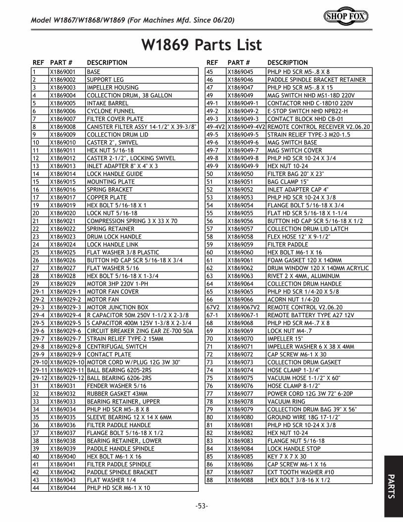
-53-
Model W1867/W1868/W1869 (For Machines Mfd. Since 06/20)PA
RTS
W1869.Parts.ListREF PART # DESCRIPTION REF PART # DESCRIPTION1 X1869001 BASE 45 X1869045 PHLP HD SCR M5-.8 X 82 X1869002 SUPPORT LEG 46 X1869046 PADDLE SPINDLE BRACKET RETAINER3 X1869003 IMPELLER HOUSING 47 X1869047 PHLP HD SCR M5-.8 X 154 X1869004 COLLECTION DRUM, 38 GALLON 49 X1869049 MAG SWITCH NHD MS1-18D 220V5 X1869005 INTAKE BARREL 49-1 X1869049-1 CONTACTOR NHD C-18D10 220V6 X1869006 CYCLONE FUNNEL 49-2 X1869049-2 E-STOP SWITCH NHD NPB22-H7 X1869007 FILTER COVER PLATE 49-3 X1869049-3 CONTACT BLOCK NHD CB-018 X1869008 CANISTER FILTER ASSY 14-1/2" X 39-3/8" 49-4V2 X1869049-4V2 REMOTE CONTROL RECEIVER V2.06.209 X1869009 COLLECTION DRUM LID 49-5 X1869049-5 STRAIN RELIEF TYPE-3 M20-1.510 X1869010 CASTER 2", SWIVEL 49-6 X1869049-6 MAG SWITCH BASE11 X1869011 HEX NUT 5/16-18 49-7 X1869049-7 MAG SWITCH COVER12 X1869012 CASTER 2-1/2", LOCKING SWIVEL 49-8 X1869049-8 PHLP HD SCR 10-24 X 3/413 X1869013 INLET ADAPTER 8" X 4" X 3 49-9 X1869049-9 HEX NUT 10-2414 X1869014 LOCK HANDLE GUIDE 50 X1869050 FILTER BAG 20" X 23"15 X1869015 MOUNTING PLATE 51 X1869051 BAG CLAMP 15"16 X1869016 SPRING BRACKET 52 X1869052 INLET ADAPTER CAP 4"17 X1869017 COPPER PLATE 53 X1869053 PHLP HD SCR 10-24 X 3/819 X1869019 HEX BOLT 5/16-18 X 1 54 X1869054 FLANGE BOLT 5/16-18 X 3/420 X1869020 LOCK NUT 5/16-18 55 X1869055 FLAT HD SCR 5/16-18 X 1-1/421 X1869021 COMPRESSION SPRING 3 X 33 X 70 56 X1869056 BUTTON HD CAP SCR 5/16-18 X 1/222 X1869022 SPRING RETAINER 57 X1869057 COLLECTION DRUM LID LATCH 23 X1869023 DRUM LOCK HANDLE 58 X1869058 FLEX HOSE 12" X 9-1/2"24 X1869024 LOCK HANDLE LINK 59 X1869059 FILTER PADDLE 25 X1869025 FLAT WASHER 3/8 PLASTIC 60 X1869060 HEX BOLT M6-1 X 1626 X1869026 BUTTON HD CAP SCR 5/16-18 X 3/4 61 X1869061 FOAM GASKET 120 X 140MM27 X1869027 FLAT WASHER 5/16 62 X1869062 DRUM WINDOW 120 X 140MM ACRYLIC28 X1869028 HEX BOLT 5/16-18 X 1-3/4 63 X1869063 RIVET 2 X 4MM, ALUMINUM29 X1869029 MOTOR 3HP 220V 1-PH 64 X1869064 COLLECTION DRUM HANDLE29-1 X1869029-1 MOTOR FAN COVER 65 X1869065 PHLP HD SCR 1/4-20 X 5/829-2 X1869029-2 MOTOR FAN 66 X1869066 ACORN NUT 1/4-2029-3 X1869029-3 MOTOR JUNCTION BOX 67V2 X1869067V2 REMOTE CONTROL V2.06.2029-4 X1869029-4 R CAPACITOR 50M 250V 1-1/2 X 2-3/8 67-1 X1869067-1 REMOTE BATTERY TYPE A27 12V29-5 X1869029-5 S CAPACITOR 400M 125V 1-3/8 X 2-3/4 68 X1869068 PHLP HD SCR M4-.7 X 829-6 X1869029-6 CIRCUIT BREAKER ZING EAR ZE-700 50A 69 X1869069 LOCK NUT M4-.729-7 X1869029-7 STRAIN RELIEF TYPE-2 15MM 70 X1869070 IMPELLER 15"29-8 X1869029-8 CENTRIFUGAL SWITCH 71 X1869071 IMPELLER WASHER 6 X 38 X 4MM29-9 X1869029-9 CONTACT PLATE 72 X1869072 CAP SCREW M6-1 X 3029-10 X1869029-10 MOTOR CORD W/PLUG 12G 3W 30" 73 X1869073 COLLECTION DRUM GASKET29-11 X1869029-11 BALL BEARING 6205-2RS 74 X1869074 HOSE CLAMP 1-3/4"29-12 X1869029-12 BALL BEARING 6206-2RS 75 X1869075 VACUUM HOSE 1-1/2" X 60"31 X1869031 FENDER WASHER 5/16 76 X1869076 HOSE CLAMP 8-1/2"32 X1869032 RUBBER GASKET 43MM 77 X1869077 POWER CORD 12G 3W 72" 6-20P33 X1869033 BEARING RETAINER, UPPER 78 X1869078 VACUUM RING34 X1869034 PHLP HD SCR M5-.8 X 8 79 X1869079 COLLECTION DRUM BAG 39" X 56"35 X1869035 SLEEVE BEARING 12 X 14 X 6MM 80 X1869080 GROUND WIRE 18G 17-1/2"36 X1869036 FILTER PADDLE HANDLE 81 X1869081 PHLP HD SCR 10-24 X 3/837 X1869037 FLANGE BOLT 5/16-18 X 1/2 82 X1869082 HEX NUT 10-2438 X1869038 BEARING RETAINER, LOWER 83 X1869083 FLANGE NUT 5/16-1839 X1869039 PADDLE HANDLE SPINDLE 84 X1869084 LOCK HANDLE STOP40 X1869040 HEX BOLT M6-1 X 16 85 X1869085 KEY 7 X 7 X 3041 X1869041 FILTER PADDLE SPINDLE 86 X1869086 CAP SCREW M6-1 X 1642 X1869042 PADDLE SPINDLE BRACKET 87 X1869087 EXT TOOTH WASHER #1043 X1869043 FLAT WASHER 1/4 88 X1869088 HEX BOLT 3/8-16 X 1/244 X1869044 PHLP HD SCR M6-1 X 10
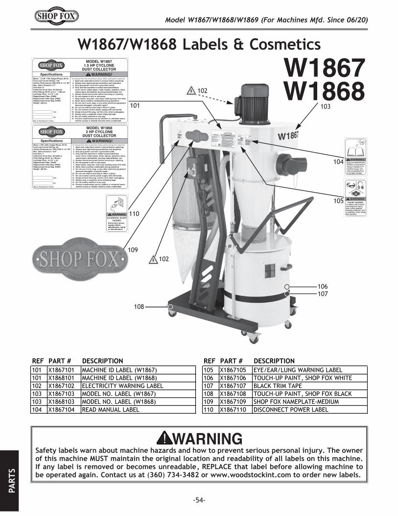
-54-
Model W1867/W1868/W1869 (For Machines Mfd. Since 06/20)PA
RTS
Safety.labels.warn.about.machine.hazards.and.how.to.prevent.serious.personal.injury..The.owner.of.this.machine.MUST.maintain.the.original.location.and.readability.of.all.labels.on.this.machine..If.any.label.is.removed.or.becomes.unreadable,.REPLACE.that.label.before.allowing.machine.to.be.operated.again..Contact.us.at.(360).734-3482.or.www.woodstockint.com.to.order.new.labels..
W1867/W1868.Labels.&.Cosmetics
W1867
WARNINGACCIDENTAL INJURY
HAZARD!Disconnect power supply before adjustments, setup or maintenance!
MODEL W18671.5 HP CYCLONE
DUST COLLECTORWARNING!
To reduce the risk of serious injury when using this machine: 1. Read and understand owner’s manual before operating. 2. Always wear approved eye protection and respirator. 3. Only plug power cord into a grounded outlet. 4. Only use this machine to collect wood dust/chips; never use to collect glass, metal, liquids, asbestos, silica,
animal parts, biohazards, burning material/ashes, etc. 5. Always disconnect power before servicing or cleaning. 6. Do not expose to rain or wet areas. 7. Keep hands, long hair, and loose clothing away from inlet. 8. Never leave machine unattended during operation. 9. Do not use if cord, plug, or any other electrical equipment
becomes damaged—promptly repair! 10. Do not use without dust bag or filters in place. 11. Do not connect cord to power supply with wet hands. 12. Grasp and pull the plug, not the cord, when unplugging. 13. Always wear a respirator when emptying bags. 14. Do not modify machine in any way. 15. Prevent unauthorized use by children or untrained users;
restrict access or disable machine when unattended.
Motor: 1.5 HP, 110V, Single-Phase, 60 HzFull-Load Current Rating: 15AAirflow Performance: 868 CFM @ 1.8" SPMax. Static Pressure: 9.7"Inlet Size: 6"Collection Drum Size: 20 GallonsFilter Rating: 99.9% at 0.2 – 1 MicronCartridge Filter: 14-1/2" x 24"Replacement Filter: D4892Replacement Filter Bag: D4893Replacement Drum Bag: D4894Weight: 265 lbs.
Mfd. for Woodstock in Taiwan
Date
S/N
Specifications
READ and UNDERSTANDMANUAL to avoid seriousinjury! If a manual is notavailable, DO NOT use machine! Instead, go towww.woodstockint.com or call (360) 734-3482.
WARNING!
WARNING!INJURY HAZARD!
To reduce risk of short and long-term injury, wear safety glasses, hearing protection, and a respirator when using this machine.
W1868101
102
103
104
105
106107
102
108
109
MODEL W18682 HP CYCLONE
DUST COLLECTORWARNING!
To reduce the risk of serious injury when using this machine: 1. Read and understand owner’s manual before operating. 2. Always wear approved eye protection and respirator. 3. Only plug power cord into a grounded outlet. 4. Only use this machine to collect wood dust/chips; never use to collect glass, metal, liquids, asbestos, silica,
animal parts, biohazards, burning material/ashes, etc. 5. Always disconnect power before servicing or cleaning. 6. Do not expose to rain or wet areas. 7. Keep hands, long hair, and loose clothing away from inlet. 8. Never leave machine unattended during operation. 9. Do not use if cord, plug, or any other electrical equipment
becomes damaged—promptly repair! 10. Do not use without dust bag or filters in place. 11. Do not connect cord to power supply with wet hands. 12. Grasp and pull the plug, not the cord, when unplugging. 13. Always wear a respirator when emptying bags. 14. Do not modify machine in any way. 15. Prevent unauthorized use by children or untrained users;
restrict access or disable machine when unattended.
Motor: 2 HP, 220V, Single-Phase, 60 HzFull-Load Current Rating: 9AAirflow Performance: 1023 CFM @ 1.2" SPMax. Static Pressure: 10.9"Inlet Size: 7"Collection Drum Size: 20 GallonsFilter Rating: 99.9% at 1 MicronCartridge Filter: 14-1/2" x 24"Replacement Filter: D4892Replacement Filter Bag: D4893Replacement Drum Bag: D4894Weight: 285 lbs.
Mfd. for Woodstock in Taiwan
Date
S/N
Specifications
110
REF PART # DESCRIPTION REF PART # DESCRIPTION101 X1867101 MACHINE ID LABEL (W1867) 105 X1867105 EYE/EAR/LUNG WARNING LABEL101 X1868101 MACHINE ID LABEL (W1868) 106 X1867106 TOUCH-UP PAINT, SHOP FOX WHITE102 X1867102 ELECTRICITY WARNING LABEL 107 X1867107 BLACK TRIM TAPE103 X1867103 MODEL NO. LABEL (W1867) 108 X1867108 TOUCH-UP PAINT, SHOP FOX BLACK103 X1868103 MODEL NO. LABEL (W1868) 109 X1867109 SHOP FOX NAMEPLATE-MEDIUM104 X1867104 READ MANUAL LABEL 110 X1867110 DISCONNECT POWER LABEL
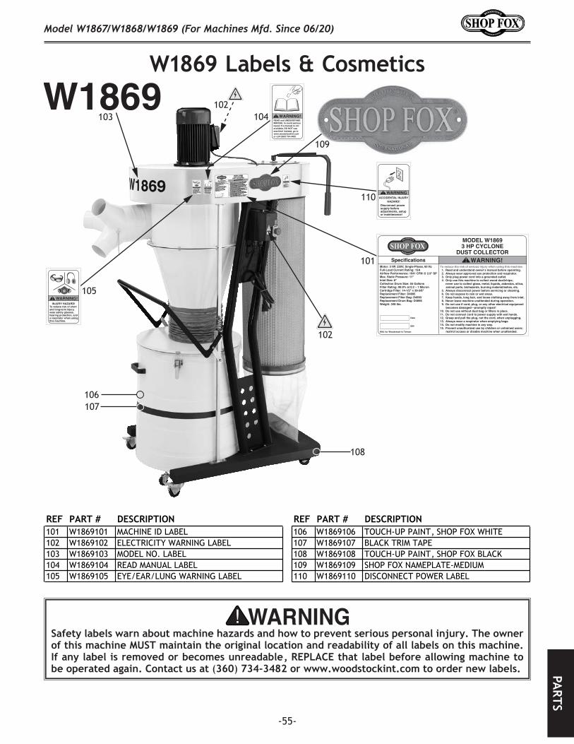
-55-
Model W1867/W1868/W1869 (For Machines Mfd. Since 06/20)PA
RTS
W1869.Labels.&.Cosmetics
Safety.labels.warn.about.machine.hazards.and.how.to.prevent.serious.personal.injury..The.owner.of.this.machine.MUST.maintain.the.original.location.and.readability.of.all.labels.on.this.machine..If.any.label.is.removed.or.becomes.unreadable,.REPLACE.that.label.before.allowing.machine.to.be.operated.again..Contact.us.at.(360).734-3482.or.www.woodstockint.com.to.order.new.labels..
W1869
WARNING!INJURY HAZARD!
To reduce risk of short and long-term injury, wear safety glasses, hearing protection, and a respirator when using this machine.
WARNINGACCIDENTAL INJURY
HAZARD!Disconnect power supply before adjustments, setup or maintenance!
MODEL W18693 HP CYCLONE
DUST COLLECTORWARNING!
To reduce the risk of serious injury when using this machine: 1. Read and understand owner’s manual before operating. 2. Always wear approved eye protection and respirator. 3. Only plug power cord into a grounded outlet. 4. Only use this machine to collect wood dust/chips; never use to collect glass, metal, liquids, asbestos, silica,
animal parts, biohazards, burning material/ashes, etc. 5. Always disconnect power before servicing or cleaning. 6. Do not expose to rain or wet areas. 7. Keep hands, long hair, and loose clothing away from inlet. 8. Never leave machine unattended during operation. 9. Do not use if cord, plug, or any other electrical equipment
becomes damaged—promptly repair! 10. Do not use without dust bag or filters in place. 11. Do not connect cord to power supply with wet hands. 12. Grasp and pull the plug, not the cord, when unplugging. 13. Always wear a respirator when emptying bags. 14. Do not modify machine in any way. 15. Prevent unauthorized use by children or untrained users;
restrict access or disable machine when unattended.
Motor: 3 HP, 220V, Single-Phase, 60 HzFull-Load Current Rating: 15AAirflow Performance: 1941 CFM @ 2.9" SPMax. Static Pressure: 11"Inlet Size: 8"Collection Drum Size: 55 GallonsFilter Rating: 99.9% at 0.2 – 1 MicronCartridge Filter: 14-1/2" x 39-3/8"Replacement Filter: D4895Replacement Filter Bag: D4893Replacement Drum Bag: D4896Weight: 348 lbs.
Mfd. for Woodstock in Taiwan
Date
S/N
Specifications
READ and UNDERSTANDMANUAL to avoid seriousinjury! If a manual is notavailable, DO NOT use machine! Instead, go towww.woodstockint.com or call (360) 734-3482.
WARNING!
102
101
102
110
103
109
104
105
106
108
107
REF PART # DESCRIPTION REF PART # DESCRIPTION101 W1869101 MACHINE ID LABEL 106 W1869106 TOUCH-UP PAINT, SHOP FOX WHITE102 W1869102 ELECTRICITY WARNING LABEL 107 W1869107 BLACK TRIM TAPE103 W1869103 MODEL NO. LABEL 108 W1869108 TOUCH-UP PAINT, SHOP FOX BLACK104 W1869104 READ MANUAL LABEL 109 W1869109 SHOP FOX NAMEPLATE-MEDIUM105 W1869105 EYE/EAR/LUNG WARNING LABEL 110 W1869110 DISCONNECT POWER LABEL


WARRANTYWARRANTY
Woodstock International, Inc. warrants all Shop Fox machinery to be free of defects from workmanship and materials for a period of two years from the date of original purchase by the original owner. This warranty does not apply to defects due directly or indirectly to misuse, abuse, negligence or accidents, lack of maintenance, or reimbursement of third party expenses incurred.
Woodstock International, Inc. will repair, replace, or arrange for a dealer refund, at its expense and option, the Shop Fox machine or machine part proven to be defective for its designed and intended use, provided that the original owner returns the product prepaid to an authorized warranty or repair facility as designated by our Bellingham, Washington office with proof of their purchase of the product within two years, and provides Woodstock International, Inc. reasonable opportunity to verify the alleged defect through inspection. If it is determined there is no defect, or that the defect resulted from causes not within the scope of Woodstock International Inc.'s warranty, then the original owner must bear the cost of storing and returning the product.
This is Woodstock International, Inc.’s sole written warranty and any and all warranties that may be implied by law, including any merchantability or fitness, for any particular purpose, are hereby limited to the duration of this written warranty. We do not warrant that Shop Fox machinery complies with the provisions of any law, acts or electrical codes. We do not reimburse for third party repairs. In no event shall Woodstock International, Inc.’s liability under this limited warranty exceed the purchase price paid for the product, and any legal actions brought against Woodstock International, Inc. shall be tried in the State of Washington, County of Whatcom. We shall in no event be liable for death, injuries to persons or property or for incidental, contingent, special or consequential damages arising from the use of our products.
Every effort has been made to ensure that all Shop Fox machinery meets high quality and durability standards. We are commited to continuously improving the quality of our products, and reserve the right to change specifications at any time.
To register the warranty, go to https://www.woodstockint.com/warranty, or scan the QR code below. You will be directed to the Warranty Registration page on www.woodstockint.com. Enter all applicable production information.
WARRANTY
WOODSTOCKINT.COM
