model vff30 repair kit installation instructions€¦ · · 2008-07-25model vff30 repair kit...
TRANSCRIPT

M O D E L V F F 3 0 R E P A I R K I T I N S T A L L A T I O N I N S T R U C T I O N S
1 Kit includes: Gasket, Filter, Screen, Diaphragm Assy., Screws 8-32 x 5/8” (2), Screws 12-24 x 5/8” (2), Seal (Viton, bonded to aluminum), Lip Seal, Valve operating pin, Retaining washer, In-structions, Seal holder (tool) and Installation pin (tool).
2 Remove 10 screws from cover which has the words “Fuel In” cast into it.
3 Remove the cover and the gasket.
INSTALLATION SAFETY PRECAUTIONS: 1. Do NOT use Teflon thread tape on any of the NPT pipe-thread fittings where fuel travels. Use a
suitable fuel-resistant joint compound. 2. Be sure to leak-check all fittings and covers for fuel tanks, using a soapy solution. 3. Be sure to use proper mounting bolts to secure the lockoff. Bolts which are too long may cause
severe damage to the lockoff.
M O D E L V F F 3 0 R E P A I R K I T I N S T A L L A T I O N I N S T R U C T I O N S
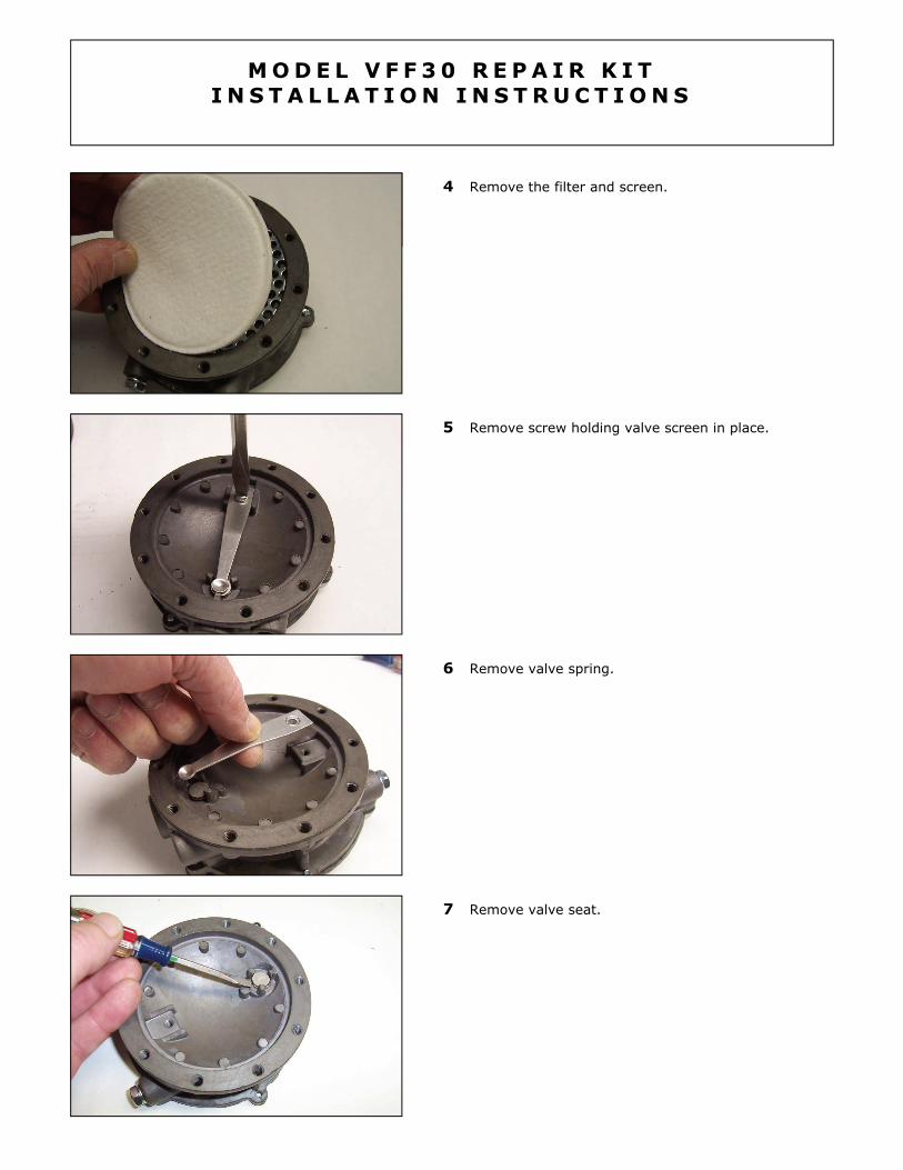
4 Remove the filter and screen.
5 Remove screw holding valve screen in place.
6 Remove valve spring.
7 Remove valve seat.

8 Remove valve operating pin.
M O D E L V F F 3 0 R E P A I R K I T I N S T A L L A T I O N I N S T R U C T I O N S
9 Using a bent paper clip or wire, fashion a hook as shown.
10 Cutaway shows the relationship of the valve spring, valve seat, valve operating pin, seal re-taining washer and o-ring. Note that removal of valve pin allows retaining washer to be removed through the “Fuel Out” (1/4” NPT) opening.
11 Insert wire hook through “Fuel Out” threaded port to hook the retaining washer, then...

M O D E L V F F 3 0 R E P A I R K I T I N S T A L L A T I O N I N S T R U C T I O N S
12 ...pull the retaining washer out of the body through the jet hole.
13 Using the same hook/wire, pull the o-ring seal through the hole in the body from which you removed the valve operating pin in step 7. Wash body, cover and jet area as needed, using kero-sene or equivalent petroleum solvent. Do NOT use carburetor cleaner, as it will attack synthetic rubber seals.
14 Seal holder should be placed as shown in photo (bottom tool). Note that the hole in the seal holder, which accepts the O-ring lip seal, is ta-pered, and that the wider end of the opening faces up. The replacement seal must be coated with silicone grease prior to inserting into holder.
Place the greased O-ring seal into the holder,
using the installation pin (upper tool). Re-coat the seal with silicone grease.
The seal must be in the position shown in the
photo groove facing up, and visible. Seal is ta-pered to match the hole in the seal holder.
15 Place the body with the filter side up, as shown.

M O D E L V F F 3 0 R E P A I R K I T I N S T A L L A T I O N I N S T R U C T I O N S
16 With the O-ring lip seal in the holder, groove visible and facing up, slide the holder into the body. Look through the Fuel In port to check positioning of the seal, above the cavity of the seal recess (see cutaway, step 10).
17 Coat the installation pin with silicone grease and push the seal through the holder and into the seat recess of the body. Remove installation pin and check for proper installation by looking into the Fuel In port. O-ring seal should be seated in the seal recess and groove should be visible.
18 Use needle nose pliers to insert seal retainer washer through the Fuel In threaded port. Again, refer to cutaway drawing, step 10.
19 Lubricate valve operating pin with silicone grease and insert in body as shown, so that pin passes through retainer washer and o-ring lip seal. Rotate pin slowly to ease passage through washer and o-ring.

M O D E L V F F 3 0 R E P A I R K I T I N S T A L L A T I O N I N S T R U C T I O N S
20 Place valve seat on top of head of operating pin, with aluminum side facing up and dark, Viton side against head of pin.
21 Add valve spring and secure with screw.
22 Lift valve spring slightly to confirm its freedom of movement.
23 Insert screen and filter.

M O D E L V F F 3 0 R E P A I R K I T I N S T A L L A T I O N I N S T R U C T I O N S
24 Place gasket on body and align with screw holes.
25 Add filter cover and secure with screws. Alter-nate side to side when tightening screws.
26 Cover and diaphragm are removed. Clean parts as necessary, using only kerosene or equivalent petroleum solvent. Do NOT use carburetor cleaner.
27 Check valve operating lever for freedom of movement. Use silicone grease to coat the sur-face of the gasket which will contact the body. Note: gasket will only align with holes when in-stalled correctly. Rivet heads in diaphragm plate should be on the cover side, not the body side.
M O D E L V F F 3 0 R E P A I R K I T I N S T A L L A T I O N I N S T R U C T I O N S
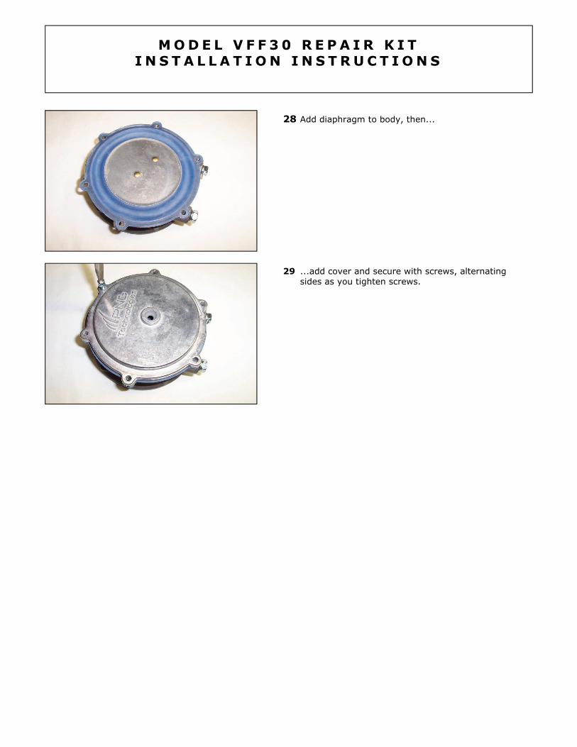
28 Add diaphragm to body, then...
29 ...add cover and secure with screws, alternating sides as you tighten screws.